EP0646676A2 - Maintenance apparatus with height adjustable support for a cylindrical brush - Google Patents
Maintenance apparatus with height adjustable support for a cylindrical brush Download PDFInfo
- Publication number
- EP0646676A2 EP0646676A2 EP94113707A EP94113707A EP0646676A2 EP 0646676 A2 EP0646676 A2 EP 0646676A2 EP 94113707 A EP94113707 A EP 94113707A EP 94113707 A EP94113707 A EP 94113707A EP 0646676 A2 EP0646676 A2 EP 0646676A2
- Authority
- EP
- European Patent Office
- Prior art keywords
- maintenance
- chassis
- maintenance tool
- care device
- roller
- Prior art date
- Legal status (The legal status is an assumption and is not a legal conclusion. Google has not performed a legal analysis and makes no representation as to the accuracy of the status listed.)
- Granted
Links
Images


Classifications
-
- E—FIXED CONSTRUCTIONS
- E01—CONSTRUCTION OF ROADS, RAILWAYS, OR BRIDGES
- E01H—STREET CLEANING; CLEANING OF PERMANENT WAYS; CLEANING BEACHES; DISPERSING OR PREVENTING FOG IN GENERAL CLEANING STREET OR RAILWAY FURNITURE OR TUNNEL WALLS
- E01H1/00—Removing undesirable matter from roads or like surfaces, with or without moistening of the surface
- E01H1/02—Brushing apparatus, e.g. with auxiliary instruments for mechanically loosening dirt
- E01H1/04—Brushing apparatus, e.g. with auxiliary instruments for mechanically loosening dirt taking- up the sweepings, e.g. for collecting, for loading
- E01H1/045—Brushing apparatus, e.g. with auxiliary instruments for mechanically loosening dirt taking- up the sweepings, e.g. for collecting, for loading the loading means being a rotating brush with horizontal axis
-
- A—HUMAN NECESSITIES
- A01—AGRICULTURE; FORESTRY; ANIMAL HUSBANDRY; HUNTING; TRAPPING; FISHING
- A01B—SOIL WORKING IN AGRICULTURE OR FORESTRY; PARTS, DETAILS, OR ACCESSORIES OF AGRICULTURAL MACHINES OR IMPLEMENTS, IN GENERAL
- A01B45/00—Machines for treating meadows or lawns, e.g. for sports grounds
-
- A—HUMAN NECESSITIES
- A01—AGRICULTURE; FORESTRY; ANIMAL HUSBANDRY; HUNTING; TRAPPING; FISHING
- A01G—HORTICULTURE; CULTIVATION OF VEGETABLES, FLOWERS, RICE, FRUIT, VINES, HOPS OR SEAWEED; FORESTRY; WATERING
- A01G20/00—Cultivation of turf, lawn or the like; Apparatus or methods therefor
- A01G20/40—Apparatus for cleaning the lawn or grass surface
- A01G20/43—Apparatus for cleaning the lawn or grass surface for sweeping, collecting or disintegrating lawn debris
Definitions
- the invention relates to a maintenance device for maintaining substantially flat surfaces, preferably in the communal, private or commercial area, such as green areas, paved areas or the like, with a device which can be attached via a drawbar to a tractor vehicle with a PTO shaft, for example a tractor or the like Chassis which has at least one axle with at least two wheels, a receiving device fastened to the chassis for goods received from the area to be maintained, such as, for example, mown plant parts, swept up impurities such as leaves, garbage, sand, grit or the like, and with one arranged on the chassis maintenance unit, which has at least one rotationally driven maintenance tool, such as a flail mower, a sweeping roller and / or a scarifying roller or the like.
- a maintenance device for maintaining substantially flat surfaces, preferably in the communal, private or commercial area, such as green areas, paved areas or the like, with a device which can be attached via a drawbar to a tractor vehicle with a PTO shaft, for example a tractor or
- DE-OS 3713445 discloses a device for the maintenance of green areas consisting of a chassis with wheels attached to a towing vehicle with a PTO shaft with wheels and a receptacle for mowed grass, leaves or the like, a maintenance unit with pendulum wheels suspended in the chassis frame and at least one roller-shaped maintenance tool, which is mounted in side plates of the maintenance unit and is driven on one side by the PTO shaft via a gear train.
- this previously known device provides that a lifting cylinder is arranged between the chassis frame and the maintenance unit, and that the roller-shaped maintenance tool is detachably received in the side plates and can be removed in the released state when the maintenance unit is raised.
- the replacement of the floor-side maintenance tool is carried out with the aid of axially pluggable axle bolts, the axle bolt being designed as a wedge element which engages through the driving V-belt hub and engages in the maintenance tool.
- the V-belt pulley and the maintenance tool are non-rotatably connected.
- This embodiment of the known device has proven particularly effective in that the floor-side maintenance tool can be replaced in a simple and quick manner. In this case, however, it is necessary that the device is raised at least to such an extent that the maintenance tool can be pulled out of the area of the chassis frame to the front or to the side after it has been dismantled. As a result, the lifting dimension of the device is essentially determined by the diameter of the maintenance tool.
- the connecting elements between the maintenance tool and the chassis frame namely the axle bolts designed as wedge elements and the driving V-belt hub or the connection of the axle bolt with the maintenance tool, have a high degree of manufacturing accuracy, so that over a predetermined operating time proper operation of this known device is guaranteed. Otherwise there is the disadvantage that there is play at lower manufacturing accuracies between the above-mentioned components, so that the connection between the chassis frame and the maintenance tool deflects over time. This results in a rattling or fluttering of the pulley, which on the one hand leads to increased noise pollution when working with the previously known device and on the other hand to a high level of maintenance of this device.
- the invention has for its object to provide a generic maintenance device that is structurally simple, good ground adaptation and can be easily adapted to different conditions of use.
- the solution to this problem provides that the maintenance tool is held in a frame or the like, which can be connected to or detached from the chassis such that the structural unit (40) thus formed can be removed from the chassis or independent of other devices. can be inserted.
- the structural unit is held on the chassis in an approximately horizontal direction laterally to the direction of travel and can be removed.
- this procedure ensures that, for the purpose of replacing or changing the care devices to be used and their maintenance, only the assembly from the respective care tool and associated frame are removed from the device or the special care area such as the sweeping head or the like, and used again can without special procedures such as erecting the chassis for spacing the maintenance tool from the floor to be maintained must be provided in case of doubt.
- the maintenance device is based on the idea of not only replacing the maintenance tool, for example the sweeping roller, flail mower or scarifying roller, but also designing a lower part of a sweeping head housing, on which the lower maintenance tool is held, as a modular unit.
- the bearing between the lower maintenance tool and the V-belt pulley can be carried out precisely and rigidly in the usual way, so that there are no deflections of the aforementioned Kind can occur.
- a V-belt pulley is assigned to the respective maintenance tool, which is adapted to the desired number of revolutions.
- the maintenance tools are driven via the PTO shaft drive, which is connected to a bevel gear, which has V-belt pulleys on the output side, one of which is assigned, for example, to an upper sweeping roller and the other of which is assigned to the bottom-side maintenance tool.
- V-belt drives remain unchanged when the maintenance tool is replaced.
- the associated V-belts are simply put on as a function of the desired number of revolutions when the maintenance tool is replaced. This can already be done at the factory. This configuration makes it much easier to replace the maintenance tool, since only the frame of the maintenance device has to be detached from the chassis and pulled out.
- the maintenance tool is stored in this frame together with the V-belt pulley.
- This frame can then be exchanged for another frame, for example one Flail mower or a scarifying roller.
- another frame for example one Flail mower or a scarifying roller.
- An upstream countershaft transmission which adjusts the corresponding speeds, can therefore be dispensed with.
- the care unit has a transport roller in addition to the care tool, which is preferably designed as a rotatingly driven brush and is arranged between the care tool and the receiving device.
- This transport roller is preferably also part of the frame, so that when the maintenance unit is replaced, both the maintenance tool and the transport roller can be removed from the chassis together with the frame. Maintenance tool and transport roller thus form a single unit.
- a maintenance device it is further provided in a maintenance device according to the invention that the maintenance tool and the transport roller are driven by a drive device which can be driven by the towing vehicle via the PTO shaft.
- a drive device which can be driven by the towing vehicle via the PTO shaft.
- This is the bevel gear already mentioned above, which carries V-belt pulleys on the output side, with the transport roller being driven via at least one V-belt pulley and the maintenance tool being driven via at least one further V-belt pulley.
- both the maintenance tool, the transport roller and the drive device have pulleys which are connected to one another via at least one drive belt, the speed of the maintenance tool and the transport roller being in relation to the belt pulley of the drive device appropriately dimensioned pulleys is adjustable.
- the drive device is preferably firmly connected to the chassis.
- the storage of the care unit is slidable in the frame, so that the spatial Assignment of the maintenance unit to the transport roller can be changed to one another.
- This feature is particularly advantageous for sweeping rollers as a floor-side maintenance tool, since these sweeping rollers should be at a certain distance from a baffle plate in order to ensure that the swept material taken up is conveyed to the further transport roller. This is necessary, for example, in adaptation to the bristle wear. For manufacturing reasons, such adjustability is also desirable for other maintenance tools in order to be able to optimize the gap width accordingly even with flail mowers.
- the frame and the maintenance unit and / or the transport roller form a sweeping head which is pivotally mounted about a pivot point, it having proven to be advantageous if the pivot point in the working direction of the device behind the wheels lies.
- the sweeping head is a separately pivotable element which, in connection with front support wheels, ensures the alignment of the sweeping roller to the floor, with height adjustability being able to provide signs of wear and tear of the maintenance tool or an exact adjustment of cutting tools of the maintenance tool.
- chassis has longitudinal beams which are preferably U-shaped in cross-section such that they allow limited torsion.
- the carriers of the chassis of a device or the sweeping head of a previously known device towards the rear pivot point have been designed as tubular profiles which are relatively rigid.
- the now proposed innovation in that longitudinal members are used that allow a limited torsion has the advantage that an inclined position of the front support wheels and thus the roller relative to the rear wheels is made possible, which leads to better ground adaptation, especially when using mowing rollers in non-planar areas Terrain leads.
- a care device 1 shown in the figures consists of a chassis 2 which has at least two longitudinal beams 3 arranged in parallel in the direction of travel, which are connected to one another via an axis arranged at right angles to the longitudinal beams 3.
- Impellers 4, which stand on the surface 5 to be machined, are rotatably arranged on both sides of the axis.
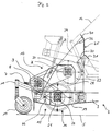
- the direction of travel of the care device 1 pulled by a towing vehicle, not shown, is shown in FIG. 1 by an arrow 6, the direction of travel in the working position of the care device 1 being indicated thereby.
- the care device 1 is connected to the towing vehicle, not shown, via a tiller, not shown, which is pivotally articulated in the horizontal direction at the front end, which lies opposite the running wheels 4.
- a connection between the towing vehicle, not shown, and the maintenance device 1 via a shaft, not shown, which is arranged on the one hand on a PTO shaft of the towing vehicle and on the other hand on a PTO shaft connection 7 of the maintenance device 1 in such a way that the torque output by the PTO shaft is transmitted to the PTO shaft connection 7 the care device 1 is transferred.
- the PTO shaft connection 7 is connected to a bevel gear 8, which is arranged in the front area of the chassis 2 and has at least two pulleys 9 on the output side.
- the care device 1 has in its front area facing the towing vehicle at least one support wheel 10 which is fixedly connected to the chassis 2 via a height adjustment device 11.
- the support wheel 10 is in this case rotatably arranged in the height adjustment device 11 so that it can follow cornering of the maintenance device 1.
- the care device 1 has a receiving device 12, which is designed as a container and has in its rear region a tilting opening, not shown, which is closed by a lid, which is also not shown and is pivotably articulated.
- the receiving device 12 is preferably tiltable about a pivot point in the rear region of the chassis, so that the material conveyed into the receiving device 12, namely, for example, mown plant parts, swept up impurities such as leaves, garbage, sand, grit or the like via the rear one with the lid closed opening can be removed from the receiving device 12.
- the receiving device 12 is pivoted about its rear pivot point by means of a linear motor, for example a hydraulic cylinder, whereby the cover of the receiving device 12 is also pivoted about its pivot point and opens the opening in the rear part of the receiving device 12.
- the care device 1 has a sweeping head 13, which consists of a frame 14 and a care unit 15 inserted into the frame 14.
- the maintenance unit 15 has a maintenance tool 16 in the form of a sweeping roller 17 (see FIG. 3), a scarifying roller 18 (see FIG. 4) or a flail mower 19 (see FIG. 5), the maintenance tool 16 having an axis 20 in its center has, at one end, at least one pulley 21 is arranged in a rotationally fixed manner, which is operatively connected to the pulley 2 of the bevel gear 8 via at least one drive belt 22.
- the care unit 15 has a transport roller 23 which is arranged above the care tool 16 in a conveying channel 24 directly in front of an inlet opening 25 of the receiving device 12.
- the transport roller 23 also has an axis of rotation 26 arranged in its center, which is provided at one end with at least one non-rotatably arranged pulley 27, which is connected to the pulley 9 of the bevel gear 8 via a drive belt 28.
- both the maintenance tool 16 and the transport roller 23 are driven in rotation in the same direction via the PTO shaft of the towing vehicle, not shown.
- the transmission of the torque of the PTO shaft and the setting of the required speed of the maintenance tool 16 and the transport roller 23 takes place here via the bevel gear 8, the pulley 9, the drive belts 22 and 28 and the pulleys 21 and 27.
- the sweeping head 3 is shown in detail in FIG. 2, so that the gear connection between the PTO shaft connection 7 and the maintenance tool 16 or the transport roller 23 is clearly recognizable.
- the maintenance device 1 can be equipped with various sweeping heads 13, so that, for example, the maintenance tools 16 shown in FIGS. 3 to 5, namely the sweeping roller 17, the scarifying roller 18 or the flail mower 19, can be inserted into the chassis 2 of the maintenance device 1.
- a pulley 21 with a larger diameter is consequently used than in the scarifying roller 18 or in the flail mower 19, since the sweeping roller 17 rotates at only 800 rpm, whereas the scarifying roller 18 and the flail mower 19 each have a number of revolutions of about 2000 min ⁇ 1 to ensure satisfactory or optimal operation. Accordingly, it is only necessary in the care device 1 according to the invention to adapt the drive belt 22 to the corresponding pulley 21 of the care tool 16.
- the drive belt 28 for driving the transport roller 23 can essentially remain unchanged in all of the above-mentioned maintenance tools 16, since the number of revolutions of the transport roller 23 is essentially independent of the number of revolutions of the maintenance device 16 with regard to the optimal functioning of this maintenance tool 16.
- the sweeping head 13 can be pivoted about a pivot point behind the impellers 4. This pivoting movement is effected by a cylinder 29.
- a spindle drive can also be provided, which enables a purely mechanical pivoting movement of the sweeping head 13.
- the sweeping head 13 is a separately pivotable element.
- the height adjustment of the sweeping head 13 is also carried out by means of the front support wheel 10, which is connected to the chassis 2 in a height-adjustable manner via the height adjustment device 11.
- the alignment of the maintenance tool 16 with respect to the surface 5 to be machined is set, on the one hand, for example to show signs of wear to compensate for the sweeping roller 17 or, on the other hand, to ensure an exact setting of the cutting tools of the flail mower 19 or the scarifying roller 18.
- the receiving device 12 is provided on the side with a V-shaped cutout which extends over the axis 20 of the maintenance tool 16.
- This configuration allows, for example, the maintenance tool 16 to be removed laterally without the chassis 2 having to be raised unnecessarily high.
- the receiving device 12 is sealed against backflow of small goods.
- the receptacle 12 in the region of its inlet opening 25 obliquely downwards and obliquely upwards to the respective receptacle surface facing diaphragms 30 and 31, which are connected to guide plates 32 and 33 projecting into the conveying channel 24 and form an L-shaped profile in cross section .
- diaphragms 30 and 31 above and below the inlet opening 25 diaphragms, not shown, are also arranged laterally in the inlet opening 25 and seal the receiving device 12 against small material flowing back.
- the receiving device 12 is designed somewhat wider than the sweeping head 13 or the inlet opening 25 to the inside of the receiving device 12.
- FIGS. 3 to 5 show various sweeping heads 13, the sweeping head 13 shown in FIG. 3 having the sweeping roller 17, which is arranged below the transport roller 23 in the conveying channel 24.
- the conveying channel 24 is formed, among other things, by a front wall 34, which at its end facing the surface 5 to be machined has a step 35 which extends forwards, ie in the direction of arrow 6 (cf. FIG. 1), to which a baffle flap directed downward 36 is attached.
- This impact flap 36 must of course yield to the not yet mowed grass, or the impurities arranged on the surface 5 to be worked, so that it can be pivoted and is therefore insofar as far from the maintenance tool 16, ie in FIG. 3 from the sweeping roller 17, in FIG in Figure 5 arranged from the flail mower 19. In the case of the flail mower 19, as shown in FIG. 5, it is thus achieved that the impact flap 36 does not get into the circumferential area of the knives 37 of the flail mower 19.
- FIGS. 3 and 5 an alternative arrangement of a baffle flap 38 is also shown in dashed lines, which is arranged closer to the circumference of the maintenance tool 16, but tangentially to the bumping tool, in comparison to the baffle flaps 36.
- This recessed impact flap 38 can be arranged either alternatively or in addition to the impact flap 36 and consequently projects forward in the direction of arrow 6, which indicates the direction of travel of the care device 1 in the working position.
- the sweeping roller 17 rotating in the direction of arrow 39 generates a sufficiently large suction due to its rotating movement to convey the absorbed material to the transport roller 23 even with this arrangement of the impact flap 38.
- FIG. 4 which shows a sweeping head 13 with a scarifying roller 18, it can also be seen that in the area of the gradation 35 a counter knife 40 running in the horizontal direction is provided as an additional device, that for further comminution of the mowed by the scarifying roller 18 and thrown up good.
- the storage of the care unit 15 in the frame 14 is slidable, so that the spatial assignment of the care tool 16 to the transport roller 23 can be changed.
- This embodiment is particularly advantageous when using a sweeping roller 17 as a maintenance tool 16, since the sweeping roller 17 should have a certain distance from the impact flap 36 in order to ensure the conveyed goods are conveyed to the further transport roller 23. This is necessary, for example, in adaptation to the bristle wear.
- adjustability is also desirable in order to be able to optimize the gap width between the knives 37 of the flail mower 19 to the impact flap 38.
- the longitudinal beams 3 are U-shaped in cross-section in order to allow a limited torsion of the longitudinal beams 3, so that an inclined position of the front support wheels 10 and thus of the maintenance tool 16 is made possible.
- a better ground adaptation of the maintenance tool 16 is achieved, in particular when using a sweeping roller 17 in non-even terrain.
- FIG. 6 shows an enlarged section of the side views, in particular of the examples in FIGS. 1 and 2, with a support which is arranged in the vicinity of the maintenance tool 16, namely in the longitudinal direction of the mobile device, on the side of the maintenance tool facing away from the support wheels 10.
- This support consists of a roller 41 which is symbolized by means of a height adjustment device 42 - symbolically adjustable in the exemplary embodiment from the chassis 2 or its longitudinal members 3.
- Such a support is advisable when it comes down to a precise spacing of the maintenance tool or its circumference from the ground to be worked, as is the case in particular when the maintenance tool is designed as a flail mower.
- the support roller 41 In order not to impair this spacing by excessive contamination of the lateral surface of the support roller 41, it is designed to be self-cleaning, i.e. a stripping device, not shown, acts on its outer surface, which removes dirt adhering to the outer surface.
- FIG. 7 shows a rear view of the maintenance tool arrangement on the bottom provided with the support in a schematic representation, from which the support roller 41, which is adjustable by means of the height adjustment 42, can be seen as extending over the majority of the Width of the care device is visible extending.
- the sweeping tool 16 is indicated with respect to its axis driven via the pulley 21 and outlined schematically with regard to its working surface.
- FIG. 8 is intended to make it very clear what can be removed as a unit 40 from all the other devices from the care device or inserted into it, specifically with a carrier 14 in which differently designed care devices 16 can be used.
- the different maintenance tools 16 are preferably provided prepared with their carriers. This avoids work associated with the pivoting of the care devices. It is only necessary to insert the respective assembly, namely carrier plus sweeping roller, carrier plus flail mower, carrier plus scarifying roller, etc., into the maintenance device, as shown in the exemplary embodiments, in a so-called sweeper head which has a transport roller arranged above the maintenance tool , which picks up the sweepings, the mowing material or the residues resulting from scarifying and transfers them into the receiving device provided for this purpose. This transport roller along with the sweeping head and the like always remains in place when a unit consisting of maintenance tool and carrier is replaced.
Abstract
Description
Die Erfindung betrifft ein Pflegegerät zur Unterhaltung von im wesentlichen ebenen Flächen, vorzugsweise im kommunalen, privaten oder gewerblichen Bereich, wie Grünflächen, befestigten Flächen oder dgl., mit einem über eine Deichsel an einem Zugfahrzeug mit Zapfwelle, bspw. einem Schlepper oder dgl. anhängbaren Fahrgestell, welches zumindest eine Achse mit zumindest zwei Laufrädern aufweist, einer an dem Fahrgestell befestigten Aufnahmevorrichtung für von der zu unterhaltenden Fläche aufgenommenes Gut, wie bspw. abgemähte Pflanzenteile, aufgekehrte Verunreinigungen wie Laub, Müll, Sand, Splitt oder dgl., und mit einem am Fahrgestell angeordneten Pflegeaggregat, welches zumindest ein drehend angetriebenes Pflegewerkzeug, wie einen Schlegelmäher, eine Kehrwalze und/oder eine Vertikutierwalze oder dgl., aufweist.The invention relates to a maintenance device for maintaining substantially flat surfaces, preferably in the communal, private or commercial area, such as green areas, paved areas or the like, with a device which can be attached via a drawbar to a tractor vehicle with a PTO shaft, for example a tractor or the like Chassis which has at least one axle with at least two wheels, a receiving device fastened to the chassis for goods received from the area to be maintained, such as, for example, mown plant parts, swept up impurities such as leaves, garbage, sand, grit or the like, and with one arranged on the chassis maintenance unit, which has at least one rotationally driven maintenance tool, such as a flail mower, a sweeping roller and / or a scarifying roller or the like.
Derartige Pflegegeräte sind aus dem Stand der Technik bekannt. Beispielsweise offenbart die DE-OS 3713445 eine Vorrichtung zur Pflege von Grünflächen bestehend aus einem mit einer Deichsel an einem Zugfahrzeug mit Zapfwelle angehängten Fahrgestell mit Laufrädern und einem Aufnahmebehälter für gemähtes Gras, Laub oder dgl., einem in den Fahrgestellrahmen pendelnd eingehängten Pflegeaggregat mit Tasträdern und wenigstens einem walzenförmigen Pflegewerkzeug, das in Seitenschilden des Pflegeaggregates gelagert ist und an einer Seite von der Zapfwelle über einen Getriebezug angetrieben ist. Um das Pflegewerkzeug in einfacher Weise auszuwechseln oder durch ein anderes Pflegewerkzeug zu ersetzen, ist bei dieser vorbekannten Vorrichtung vorgesehen, daß zwischen dem Fahrgestellrahmen und dem Pflegeaggregat ein Hubzylinder angeordnet ist, und daß das walzenförmige Pflegewerkzeug in den Seitenschilden lösbar aufgenommen und in gelöstem Zustand bei angehobenem Pflegeaggregat entnehmbar ist.Care devices of this type are known from the prior art. For example, DE-OS 3713445 discloses a device for the maintenance of green areas consisting of a chassis with wheels attached to a towing vehicle with a PTO shaft with wheels and a receptacle for mowed grass, leaves or the like, a maintenance unit with pendulum wheels suspended in the chassis frame and at least one roller-shaped maintenance tool, which is mounted in side plates of the maintenance unit and is driven on one side by the PTO shaft via a gear train. In order to replace the maintenance tool in a simple manner or to replace it with another maintenance tool, this previously known device provides that a lifting cylinder is arranged between the chassis frame and the maintenance unit, and that the roller-shaped maintenance tool is detachably received in the side plates and can be removed in the released state when the maintenance unit is raised.
Bei dieser vorbekannten Vorrichtung wird das Auswechseln des bodenseitigen Pflegewerkzeuges mit Hilfe von seitlich steckbaren Achsbolzen vorgenommen, wobei der Achsbolzen als Keilelement ausgebildet ist, welches die antreibende Keilriemennabe durchgreift und in das Pflegewerkzeug eingreift. Hierdurch sind die Keilriemenscheibe und das Pflegewerkzeug verdrehfest verbunden. Diese Ausgestaltung der vorbekannten Vorrichtung hat sich insbesondere dahingehend bewährt, daß das bodenseitige Pflegewerkzeug in einfacher und schneller Weise auswechselbar ist. Hierbei ist es jedoch notwendig, daß die Vorrichtung zumindest so weit angehoben wird, daß das Pflegewerkzeug nach seiner Demontage nach vorne oder zur Seite aus dem Bereich des Fahrgestellrahmens herausziehbar ist. Demzufolge ist das Anhebemaß der Vorrichtung im wesentlichen durch den Durchmesser des Pflegewerkzeuges bestimmt. Darüberhinaus ist es bei der vorgenannten Vorrichtung notwendig, daß die Verbindungselemente zwischen dem Pflegewerkzeug und dem Fahrgestellrahmen, nämlich die als Keilelemente ausgebildeten Achsbolzen und die antreibende Keilriemennabe bzw. die Verbindung des Achsbolzens mit dem Pflegewerkzeug eine hohe Fertigungsgenauigkeit aufweisen, so daß über eine vorbestimmte Betriebsdauer ein einwandfreier Betrieb dieser vorbekannten Vorrichtung gewährleistet ist. Andernfalls tritt der Nachteil auf, daß bei geringeren Fertigungsgenauigkeiten zwischen den voranstehend genannten Bauelementen ein Spiel auftritt, so daß die Verbindung zwischen dem Fahrgestellrahmen und dem Pflegewerkzeug mit der Zeit ausschlägt. Hieraus resultiert ein Rattern bzw. Flattern der Riemenscheibe, was einerseits zu einer erhöhten Lärmbelästigung bei der Arbeit mit der vorbekannten Vorrichtung und andererseits zu einem hohen Wartungsaufwand dieser Vorrichtung führt. Darüberhinaus ist es bei der vorbekannten Vorrichtung erforderlich, in Anpassung an die unterschiedlichen Drehzahlen je nach Pflegewerkzeug ein Vorgetriebe vorzusehen, mit dem die Drehzahl entsprechend den Anforderungen des Pflegewerkzeuges angepaßt wird.In this known device, the replacement of the floor-side maintenance tool is carried out with the aid of axially pluggable axle bolts, the axle bolt being designed as a wedge element which engages through the driving V-belt hub and engages in the maintenance tool. As a result, the V-belt pulley and the maintenance tool are non-rotatably connected. This embodiment of the known device has proven particularly effective in that the floor-side maintenance tool can be replaced in a simple and quick manner. In this case, however, it is necessary that the device is raised at least to such an extent that the maintenance tool can be pulled out of the area of the chassis frame to the front or to the side after it has been dismantled. As a result, the lifting dimension of the device is essentially determined by the diameter of the maintenance tool. In addition, it is necessary in the aforementioned device that the connecting elements between the maintenance tool and the chassis frame, namely the axle bolts designed as wedge elements and the driving V-belt hub or the connection of the axle bolt with the maintenance tool, have a high degree of manufacturing accuracy, so that over a predetermined operating time proper operation of this known device is guaranteed. Otherwise there is the disadvantage that there is play at lower manufacturing accuracies between the above-mentioned components, so that the connection between the chassis frame and the maintenance tool deflects over time. This results in a rattling or fluttering of the pulley, which on the one hand leads to increased noise pollution when working with the previously known device and on the other hand to a high level of maintenance of this device. In addition, in the known device, it is necessary to provide a preliminary gear in accordance with the different rotational speeds, depending on the maintenance tool, with which the rotational speed corresponds to the requirements of the maintenance tool is adjusted.
Ausgehend von diesem Stand der Technik liegt der Erfindung die Aufgabe zugrunde, ein gattungsgemäßes Pflegegerät zu schaffen, das konstruktiv einfach gestaltet ist, eine gute Bodenanpassung ermöglicht und in einfacher Weise an verschiedene Einsatzbedingungen anpaßbar ist.Based on this prior art, the invention has for its object to provide a generic maintenance device that is structurally simple, good ground adaptation and can be easily adapted to different conditions of use.
Die Lösung dieser Aufgabenstellung sieht vor, daß das Pflegewerkzeug in einem Rahmen oder dgl. gehalten ist, der mit dem Fahrgestell derart verbindbar bzw. von diesem lösbar ist, daß die so gebildete Baueinheit (40) unabhängig von weiteren Einrichtungen aus dem Fahrgestell herausnehmbar bzw. einschiebbar ist.The solution to this problem provides that the maintenance tool is held in a frame or the like, which can be connected to or detached from the chassis such that the structural unit (40) thus formed can be removed from the chassis or independent of other devices. can be inserted.
In besonders bevorzugter Ausführung ist die Baueinheit dabei in etwa horizontaler Richtung seitlich zur Fahrtrichtung ein- und ausbaubar an dem Fahrgestell gehalten.In a particularly preferred embodiment, the structural unit is held on the chassis in an approximately horizontal direction laterally to the direction of travel and can be removed.
Insgesamt ist durch diese Vorgehensweise sichergestellt, daß zum Zwecke des Auswechselns bzw. der Änderung der einzusetzenden Pflegegeräte und deren Wartung ausschließlich die Baueinheit aus jeweiligen Pflegewerkzeug und zugehörigem Rahmen aus dem Gerät bzw. dem speziellem Pflegebereich wie Kehrkopf oder dgl., herausgenommen und wieder eingesetzt werden kann, ohne daß im Zweifelsfalle besondere Vorgehensweisen wie das Aufrichten des Fahrgestelles zur Beabstandung des Pflegewerkzeuges von dem zu pflegenden Boden vorgesehen sein müssen.Overall, this procedure ensures that, for the purpose of replacing or changing the care devices to be used and their maintenance, only the assembly from the respective care tool and associated frame are removed from the device or the special care area such as the sweeping head or the like, and used again can without special procedures such as erecting the chassis for spacing the maintenance tool from the floor to be maintained must be provided in case of doubt.
Das erfindungsgemäße Pflegegerät geht von der Vorstellung aus, nicht nur das Pflegewerkzeug bspw. die Kehrwalze, den Schlegelmäher oder die Vertikutierwalze auszuwechseln, sondern einen unteren Teilbereich eines Kehrkopfgehäuses, an dem das untere Pflegewerkzeug gehalten ist, als Baueinheit auswechselbar zu gestalten. Hierdurch kann man die Lagerung zwischen dem unteren Pflegewerkzeug und der Keilriemenscheibe in üblicher Weise exakt und starr ausführen, so daß keine Ausschlagerscheinungen der voranstehend genannten Art auftreten können. Hierbei ist von besonderem Vorteil, daß dem jeweiligen Pflegewerkzeug eine Keilriemenscheibe zugeordnet ist, die an die gewünschte Umdrehungszahl angepaßt ist. Somit ist es bspw. möglich, eine Kehrwalze mit einer größeren Keilriemenscheibe zu versehen, so daß die Kehrwalze mit einer vorteilhaften Umdrehungsgeschwindigkeit von 800 min⁻¹ läuft, wobei Mähgeräte eine kleinere Keilriemenscheibe haben, so daß derartige Mähgeräte mit einer Umdrehungsgeschwindigkeit von 2000 min⁻¹ betrieben werden können. Hierbei hat es sich als vorteilhaft erwiesen, daß bei der langsam umlaufenden Kehrwalze auch die zu übertragenden Drehmomente kleiner sind als bei den schnell umlaufenden Mähwalzen, wie Schlegelmäher oder Vertikutierwalze. Es kann demzufolge vorgesehen sein, daß die langsam umlaufende Kehrwalze nur zwei Keilriemenscheiben auf ihrer Achse trägt, da ein Antrieb mit nur zwei parallelen Keilriemen ausreicht, um das entsprechende Drehmoment zu übertragen. Bei den voranstehend genannten Schlegelmähern und Vertikutierwalzen sind nicht nur höhere Umdrehungsgeschwindigkeiten, sondern auch höhere Drehmomente erforderlich, weshalb man bei derartigen Pflegewerkzeugen mehrere, vorzugsweise drei Übertragungsriemen in Parallelschaltung vorsehen kann, so daß diese Pflegewerkzeuge auch über zumindest drei Keilriemenscheiben verfügen, die parallel und koaxial auf der entsprechenden Drehachse des Pflegewerkzeuges drehfest angeordnet sind.The maintenance device according to the invention is based on the idea of not only replacing the maintenance tool, for example the sweeping roller, flail mower or scarifying roller, but also designing a lower part of a sweeping head housing, on which the lower maintenance tool is held, as a modular unit. As a result, the bearing between the lower maintenance tool and the V-belt pulley can be carried out precisely and rigidly in the usual way, so that there are no deflections of the aforementioned Kind can occur. It is particularly advantageous that a V-belt pulley is assigned to the respective maintenance tool, which is adapted to the desired number of revolutions. Thus, it is possible, for example, to provide a sweeper roller with a larger V-belt pulley, so that the sweeper roller runs at an advantageous rotational speed of 800 min⁻¹, with mowers having a smaller V-belt pulley, so that such mowers with a rotational speed of 2000 min⁻¹ can be operated. It has proven to be advantageous here that the torques to be transmitted are also smaller in the case of the slowly rotating brush roller than in the case of the rapidly rotating mower rollers, such as flail mowers or scarifying rollers. It can therefore be provided that the slowly rotating brush roller carries only two V-belt pulleys on its axis, since a drive with only two parallel V-belts is sufficient to transmit the corresponding torque. The above-mentioned flail mowers and scarifying rollers require not only higher speeds of rotation, but also higher torques, which is why several, preferably three, transmission belts can be provided in parallel in maintenance tools of this type, so that these maintenance tools also have at least three V-belt pulleys that are parallel and coaxial the corresponding axis of rotation of the maintenance tool are arranged in a rotationally fixed manner.
Der Antrieb der Pflegewerkzeuge erfolgt über den Zapfwellenantrieb, der mit einem Kegelgetriebe verbunden ist, welches ausgangsseitig Keilriemenscheiben hat, deren eine beispielsweise einer oberen Kehrwalze und deren andere dem bodenseitigen Pflegewerkzeug zugeordnet ist. Diese Keilriementriebe bleiben beim Auswechseln des Pflegewerkzeuges unverändert. Es werden lediglich beim Auswechseln des Pflegewerkzeuges die zugehörigen Keilriemen in Abhängigkeit der gewünschten Umdrehungszahl aufgelegt. Dies kann bereits werkseitig ausgeführt werden. Durch diese Ausgestaltung ist das Auswechseln des Pflegewerkzeuges wesentlich vereinfacht, da lediglich der Rahmen des Pflegegerätes aus dem Fahrgestell gelöst und herausgezogen werden muß. In diesem Rahmen ist das Pflegewerkzeug zusammen mit der Keilriemenscheibe gelagert. Dieser Rahmen kann dann gegen einen anderen Rahmen getauscht werden, der beispielsweise einen Schlegelmäher oder eine Vertikutierwalze aufweist. In diesem Fall ist nach dem Einbau eines derartig ausgebildeten Rahmens nur noch ein entsprechender Keilriemen mit einer unterschiedlichen Länge aufzulegen. Auf ein vorgeschaltetes Vorgelegegetriebe, welches die entsprechenden Drehzahlen anpaßt kann demzufolge verzichtet werden.The maintenance tools are driven via the PTO shaft drive, which is connected to a bevel gear, which has V-belt pulleys on the output side, one of which is assigned, for example, to an upper sweeping roller and the other of which is assigned to the bottom-side maintenance tool. These V-belt drives remain unchanged when the maintenance tool is replaced. The associated V-belts are simply put on as a function of the desired number of revolutions when the maintenance tool is replaced. This can already be done at the factory. This configuration makes it much easier to replace the maintenance tool, since only the frame of the maintenance device has to be detached from the chassis and pulled out. The maintenance tool is stored in this frame together with the V-belt pulley. This frame can then be exchanged for another frame, for example one Flail mower or a scarifying roller. In this case, after installing such a frame, only a corresponding V-belt with a different length has to be put on. An upstream countershaft transmission, which adjusts the corresponding speeds, can therefore be dispensed with.
Nach einem weiteren Merkmal der Erfindung ist vorgesehen, daß das Pflegeaggregat neben dem Pflegewerkzeug eine Transportwalze aufweist, die vorzugsweise als drehend angetriebene Bürste ausgebildet und zwischen dem Pflegewerkzeug und der Aufnahmevorrichtung angeordnet ist. Diese Transportwalze ist vorzugsweise ebenfalls Bestandteil des Rahmens, so daß beim Auswechseln des Pflegeaggregats sowohl das Pflegewerkzeug als auch die Transportwalze zusammen mit dem Rahmen aus dem Fahrgestell demontierbar sind. Pflegewerkzeug und Transportwalze bilden somit eine Baueinheit.According to a further feature of the invention, it is provided that the care unit has a transport roller in addition to the care tool, which is preferably designed as a rotatingly driven brush and is arranged between the care tool and the receiving device. This transport roller is preferably also part of the frame, so that when the maintenance unit is replaced, both the maintenance tool and the transport roller can be removed from the chassis together with the frame. Maintenance tool and transport roller thus form a single unit.
Es ist ferner bei einem erfindungsgemäßen Pflegegerät vorgesehen, daß das Pflegewerkzeug und die Transportwalze über eine Antriebseinrichtung angetrieben sind, die über die Zapfwelle durch das Zugfahrzeug antreibbar ist. Hierbei handelt es sich um das vorstehend bereits erwähnte Kegelgetriebe, das ausgangsseitig Keilriemenscheiben trägt, wobei über zumindest eine Keilriemenscheibe die Transportwalze und über zumindest eine weitere Keilriemenscheibe das Pflegewerkzeug angetrieben wird. Hierzu ist es nach einem weiteren vorteilhaften Merkmal der Erfindung vorgesehen, daß sowohl das Pflegewerkzeug, die Transportwalze als auch die Antriebseinrichtung Riemenscheiben haben, die miteinander über zumindest einen Treibriemen verbunden sind, wobei die Drehzahl des Pflegewerkzeuges und der Transportwalze durch im Verhältnis zur Riemenscheibe der Antriebseinrichtung entsprechend dimensionierte Riemenscheiben einstellbar ist.It is further provided in a maintenance device according to the invention that the maintenance tool and the transport roller are driven by a drive device which can be driven by the towing vehicle via the PTO shaft. This is the bevel gear already mentioned above, which carries V-belt pulleys on the output side, with the transport roller being driven via at least one V-belt pulley and the maintenance tool being driven via at least one further V-belt pulley. For this purpose, it is provided according to a further advantageous feature of the invention that both the maintenance tool, the transport roller and the drive device have pulleys which are connected to one another via at least one drive belt, the speed of the maintenance tool and the transport roller being in relation to the belt pulley of the drive device appropriately dimensioned pulleys is adjustable.
Die Antriebseinrichtung ist vorzugsweise fest mit dem Fahrgestell verbunden.The drive device is preferably firmly connected to the chassis.
Nach einem weiteren Merkmal der Erfindung ist vorgesehen, daß die Lagerung des Pflegeaggregates im Rahmen verschieblich ausgebildet ist, so daß die räumliche Zuordnung des Pflegeaggregates zur Transportwalze zueinander änderbar ist. Dieses Merkmal ist insbesondere bei Kehrwalzen als bodenseitiges Pflegewerkzeug vorteilhaft, da diese Kehrwalze einen bestimmten Abstand zu einem Prallblech haben sollen, um die Förderung des aufgenommenen Kehrgutes zur weiteren Transportwalze sicherzustellen. Dies ist beispielsweise in Anpassung an die Borstenabnutzung erforderlich. Aus fertigungstechnischen Gründen ist eine solche Einstellbarkeit aber auch bei anderen Pflegewerkzeugen wünschenswert um die Spaltbreite auch bei Schlegelmähern entsprechend optimieren zu können.According to a further feature of the invention it is provided that the storage of the care unit is slidable in the frame, so that the spatial Assignment of the maintenance unit to the transport roller can be changed to one another. This feature is particularly advantageous for sweeping rollers as a floor-side maintenance tool, since these sweeping rollers should be at a certain distance from a baffle plate in order to ensure that the swept material taken up is conveyed to the further transport roller. This is necessary, for example, in adaptation to the bristle wear. For manufacturing reasons, such adjustability is also desirable for other maintenance tools in order to be able to optimize the gap width accordingly even with flail mowers.
Nach einem weiteren Merkmal der Erfindung ist vorgesehen, daß der Rahmen und das Pflegeaggregat und/oder der Transportwalze einen Kehrkopf bilden, der um einen Schwenkpunkt verschwenkbar gelagert ist, wobei es sich als vorteilhaft herausgestellt hat, wenn der Schwenkpunkt in Arbeitsfahrtrichtung der Vorrichtung hinter den Laufrädern liegt. Der Kehrkopf ist also insoweit ein getrennt verschwenkbares Element, welches im Zusammenhang mit vorderen Stützrädern die Ausrichtung der Kehrwalze zum Boden sicherstellt, wobei noch eine Höhenverstellbarkeit vorgesehen sein kann, um Abnutzerscheinungen des Pflegewerkzeuges oder eine genaue Einstellung von Schneidwerkzeugen des Pflegewerkzeuges sicherzustellen.According to a further feature of the invention, it is provided that the frame and the maintenance unit and / or the transport roller form a sweeping head which is pivotally mounted about a pivot point, it having proven to be advantageous if the pivot point in the working direction of the device behind the wheels lies. In this respect, the sweeping head is a separately pivotable element which, in connection with front support wheels, ensures the alignment of the sweeping roller to the floor, with height adjustability being able to provide signs of wear and tear of the maintenance tool or an exact adjustment of cutting tools of the maintenance tool.
Es ist darüberhinaus weiterhin vorgesehen, daß das Fahrgestell Längsträger aufweist, die derart, vorzugsweise im Querschnitt U-förmig ausgebildet sind, daß sie eine begrenzte Torsion erlauben.It is furthermore provided that the chassis has longitudinal beams which are preferably U-shaped in cross-section such that they allow limited torsion.
Bislang hat man die Träger des Fahrgestells einer Vorrichtung bzw. des Kehrkopfes einer vorbekannten Vorrichtung zum hinteren Drehpunkt hin als Rohrprofile ausgebildet, die verhältnismäßig biegesteif sind. Die nunmehr vorgeschlagene Neuerung dahingehend, daß Längsträger verwendet werden, die eine begrenzte Torsion erlauben hat den Vorteil, daß eine Schräglage der vorderen Stützräder und damit der Walze gegenüber den Hinterrädern ermöglicht wird, die zu einer besseren Bodenanpassung, insbesondere bei Einsatz von Mähwalzen in nicht ebenen Gelände führt.So far, the carriers of the chassis of a device or the sweeping head of a previously known device towards the rear pivot point have been designed as tubular profiles which are relatively rigid. The now proposed innovation in that longitudinal members are used that allow a limited torsion has the advantage that an inclined position of the front support wheels and thus the roller relative to the rear wheels is made possible, which leads to better ground adaptation, especially when using mowing rollers in non-planar areas Terrain leads.
Schließlich ist es nach einem weiteren Merkmal der Erfindung vorgesehen, alle Abtriebselemente vom Getriebe zu den Pflegewerkzeugen bzw. zur Transportwalze auf derselben Seite des Fahrgestells bzw. des Rahmens anzuordnen. Diese neue Ausbildung einer erfindungsgemäßen Vorrichtung rückt von der bisherigen Vorstellung ab, nämlich eine Reihenschaltung vorzusehen, daß heißt an eine Seite den Antrieb des bodenseitigen Pflegewerkzeuges und an der anderen Seite den Antrieb der Transportwalze vorzusehen. Die erfindungsgemäße Ausgestaltung der Vorrichtung mit der Anordnung aller Abtriebselemente vom Getriebe zu den Pflegewerkzeugen auf ein- und derselben Seite hat den Vorteil, daß die Wartung des Antriebs-bzw. Abtriebselemente von nur einer Seite her möglich ist, so daß beispielsweise eine Wartung auch bei eingebautem Kehrkopf problemlos möglich ist.Finally, it is provided according to a further feature of the invention to arrange all the output elements from the transmission to the maintenance tools or to the transport roller on the same side of the chassis or the frame. This new design of a device according to the invention moves away from the previous idea, namely to provide a series connection, that is to say on one side the drive of the floor-side maintenance tool and on the other side the drive of the transport roller. The inventive design of the device with the arrangement of all output elements from the transmission to the maintenance tools on one and the same side has the advantage that the maintenance of the drive or. Output elements from only one side is possible, so that, for example, maintenance is easily possible even with the sweeping head installed.
Weitere Merkmale und Vorteile der Erfindung ergeben sich aus der nachfolgenden Beschreibung, in der bevorzugte Ausführungsformen des erfindungsgemäßen Pflegegerätes dargestellt sind. In den Zeichnungen zeigen:
- Figur 1
- eine schematisch dargestellte Seitenansicht eines Pflegegerätes mit einem Kehrkopf;
Figur 2- eine vergrößert dargestellte Seitenansicht des Kehrkopfes des Pflegegerätes gemäß Figur 1;
Figur 3- eine erste Ausführungsform eines Kehrkopfes mit einer Kehrwalze;
Figur 4- eine zweite Ausführungsform eines Kehrkopfes mit einem Schlegelmäher;
Figur 5- eine dritte Ausführungsform eines Kehrkopfes mit einer Vertikutierwalze.
Figur 6- eine modifizierte Ausführung des Kehrkopfes, insbesondere für einen Schlegelmäher;
Figur 7- eine schematisierte Rückansicht des unteren Bereiches der Ausführung gemäß Figur 6;
Figur 8- eine Seitenansicht der aus Pflegewerkzeug und Rahmen gebildeten Baueinheit.
- Figure 1
- a schematically illustrated side view of a maintenance device with a sweeping head;
- Figure 2
- an enlarged side view of the sweeping head of the care device according to Figure 1;
- Figure 3
- a first embodiment of a sweeping head with a sweeping roller;
- Figure 4
- a second embodiment of a sweeping head with a flail mower;
- Figure 5
- a third embodiment of a sweeping head with a scarifying roller.
- Figure 6
- a modified version of the sweeping head, especially for a flail mower;
- Figure 7
- a schematic rear view of the lower region of the embodiment according to Figure 6;
- Figure 8
- a side view of the unit formed from the maintenance tool and frame.
Ein in den Figuren dargestelltes Pflegegerät 1 besteht aus einem Fahrgestell 2, welches zumindest zwei in Fahrtrichtung parallel angeordnete Längsträger 3 aufweist, welche über eine im rechten Winkel zu den Längsträgern 3 angeordnete Achse miteinander verbunden sind. An der Achse sind beidseitig Laufräder 4 drehbar angeordnet, welche auf der zu bearbeitenden Fläche 5 aufstehen.A care device 1 shown in the figures consists of a
Die Fahrtrichtung des von einem nicht dargestellten Zugfahrzeuges gezogenen Pflegegerätes 1 ist in Figur 1 durch einen Pfeil 6 dargestellt, wobei hierdurch die Fahrtrichtung in Arbeitsstellung des Pflegegerätes 1 angezeigt ist. Die Verbindung des Pflegegerätes 1 mit dem nicht dargestellten Zugfahrzeug erfolgt über eine nicht dargestellte Deichsel, die am vorderen Ende, welches den Laufrädern 4 gegenüberliegt, in horizontaler Richtung schwenkbar angelenkt ist. Darüberhinaus besteht zwischen dem nicht dargestellten Zugfahrzeug und dem Pflegegerät 1 eine Verbindung über eine nicht dargestellte Welle, die einerseits an einer Zapfwelle des Zugfahrzeuges und andererseits an einem Zapfwellenanschluß 7 des Pflegegerätes 1 derart angeordnet ist, daß das von der Zapfwelle abgegebene Drehmoment auf den Zapfwellenanschluß 7 des Pflegegerätes 1 übertragen wird.The direction of travel of the care device 1 pulled by a towing vehicle, not shown, is shown in FIG. 1 by an
Der Zapfwellenanschluß 7 ist getrieblich mit einem Kegelgetriebe 8 verbunden, welches im vorderen Bereich des Fahrgestells 2 angeordnet ist und abtriebsseitig zumindest zwei Riemenscheiben 9 aufweist.The
Darüberhinaus hat das Pflegegerät 1 in seinem vorderen, dem Zugfahrzeug zugewandten Bereich mindestens ein Stützrad 10, welches über eine Höhenverstellvorrichtung 11 mit dem Fahrgestell 2 fest verbunden ist. Das Stützrad 10 ist hierbei drehbar in der Höhenverstellvorrichtung 11 angeordnet, so daß es Kurvenfahrten des Pflegegerätes 1 folgen kann.In addition, the care device 1 has in its front area facing the towing vehicle at least one
Ferner weist das Pflegegerät 1 eine Aufnahmevorrichtung 12 auf, die als Behälter ausgebildet ist und in ihrem hinteren Bereich eine nicht dargestellte Auskippöffnung hat, welche von einem ebenfalls nicht dargestellten und schwenkbeweglich angelenkten Deckel verschlossen ist. Die Aufnahmevorrichtung 12 ist vorzugsweise um einen Drehpunkt im hinteren Bereich des Fahrgestells kippbar, so daß das in die Aufnahmevorrichtung 12 geförderte Gut, nämlich beispielsweise abgemähte Pflanzenteile, aufgekehrte Verunreinigungen, wie Laub, Müll, Sand, Splitt oder dergleichen über die hintere, mit dem Deckel verschlossene Öffnung aus der Aufnahmevorrichtung 12 entfernbar sind. Hierzu wird die Aufnahmevorrichtung 12 mittels eines Linearmotors, beispielsweise eines Hydraulikzylinders um ihren hinteren Drehpunkt verschwenkt, wodurch der Deckel der Aufnahmevorrichtung 12 ebenfalls um seinen Drehpunkt verschwenkt wird und die Öffnung im hinteren Teil der Aufnahmevorrichtung 12 freigibt.Furthermore, the care device 1 has a receiving
Schließlich weist das Pflegegerät 1 einen Kehrkopf 13 auf, der aus einem Rahmen 14 und einem in den Rahmen 14 eingesetzten Pflegeaggregat 15 besteht.Finally, the care device 1 has a
Das Pflegeaggregat 15 weist ein Pflegewerkzeug 16 in Form einer Kehrwalze 17 (vgl. Figur 3), einer Vertikutierwalze 18 (vgl. Figur 4) oder eines Schlegelmähers 19 (vgl. Figur 5) auf, wobei das Pflegewerkzeug 16 in seinem Zentrum eine Achse 20 hat, auf deren einen Ende zumindest eine Riemenscheibe 21 drehfest angeordnet ist, welche getrieblich über zumindest einen Treibriemen 22 mit der Riemenscheibe 2 des Kegelgetriebes 8 verbunden ist.The
Schließlich weist das Pflegeaggregat 15 eine Transportwalze 23 auf, die oberhalb des Pflegewerkzeuges 16 in einem Förderkanal 24 unmittelbar vor einer Einlaßöffnung 25 der Aufnahmevorrichtung 12 angeordnet ist. Die Transportwalze 23 weist ebenfalls eine in ihrem Zentrum angeordnete Drehachse 26 auf, die an ihrem einen Ende mit zumindest einer drehfest angeordneten Riemenscheibe 27 versehen ist, welche über einen Treibriemen 28 getrieblich mit der Riemenscheibe 9 des Kegelgetriebes 8 verbunden ist.Finally, the
Somit werden über die nicht dargestellte Zapfwelle des Zugfahrzeuges sowohl das Pflegewerkzeug 16 als auch die Transportwalze 23 in gleicher Richtung drehend angetrieben. Die Übertragung des Drehmomentes der Zapfwelle und die Einstellung der erforderlichen Drehzahl des Pflegewerkzeuges 16 und der Transportwalze 23 erfolgt hierbei über das Kegelgetriebe 8, die Riemenscheibe 9, die Treibriemen 22 und 28 sowie die Riemenscheiben 21 und 27.Thus, both the
In der Figur 2 ist der Kehrkopf 3 detailliert dargestellt, so daß die getriebliche Verbindung zwischen dem Zapfwellenanschluß 7 und dem Pflegewerkzeug 16 bzw. der Transportwalze 23 deutlich erkennbar ist.The
Aus der Figur 2 ist ebenfalls zu erkennen, daß der Rahmen 14 des Kehrkopfes 13 von den Längsträgern 3 getrennt ist, so daß der gesamte Kehrkopf 13 bestehend aus dem Rahmen 14 dem Pflegewerkzeug 16 und der Transportwalze 23 seitlich, daß heißt in Richtung der Bildebene aus dem Fahrgestell 2 herausgezogen werden kann. Hierzu ist es lediglich notwendig, die getriebliche Verbindung zwischen der Riemenscheibe 9 und den Riemenscheiben 21 bzw. 27 zu lösen, daß heißt die Treibriemen 22 und 28 von den entsprechenden Riemenscheiben 21 und 27 herunterzunehmen, woraufhin der Kehrkopf 13 nach Lösen seiner Verbindung mit dem Fahrgestell 2 herausgezogen werden kann. Durch diese Ausgestaltung ist einerseits die Wartung des Kehrkopfes 13 und insbesondere des Pflegewerkzeuges 16 wesentlich vereinfacht. Darüber hinaus kann das Pflegegerät 1 mit verschiedenen Kehrköpfen 13 ausgestattet werden, so daß beispielsweise die in den Figuren 3 bis 5 dargestellten Pflegewerkzeuge 16, nämlich der Kehrwalze 17, die Vertikutierwalze 18 oder der Schlegelmäher 19 in das Fahrgestell 2 des Pflegegerätes 1 eingesetzt werden können. Hierdurch wird ein multifunktionelles Pflegegerät 1 geschaffen, welches in einfacher und schneller Weise auf die Arbeitsanforderungen zur Pflege bestimmter Flächen 5 anpaßbar ist. Da die Kehrwalze 17 mit einer im Vergleich zur Vertikutierwalze 18 bzw. zum Schlegelmäher 19 geringeren Umdrehungszahl angetrieben wird muß die Umdrehungszahl durch bestimmte Größen der Riemenscheibe 21 angepaßt werden. Bei der Kehrwalze 17 kommt demzufolge eine Riemenscheibe 21 mit einem größeren Durchmesser zum Einsatz als bei der Vertikutierwalze 18 bzw. bei dem Schlegelmäher 19, da die Kehrwalze 17 mit nur 800 min⁻¹ umläuft, wogegen die Vertikutierwalze 18 und der Schlegelmäher 19 jeweils eine Umdrehungszahl von etwa 2000 min⁻¹ benötigen, um eine zufriedenstellende bzw. optimale Arbeitsweise zu gewährleisten. Demzufolge ist es bei dem erfindungsgemäßen Pflegegerät 1 lediglich notwendig, den Treibriemen 22 an die entsprechende Riemenscheibe 21 des Pflegewerkzeuges 16 anzupassen. Der Treibriemen 28 zum Antrieb der Transportwalze 23 kann hierbei im wesentlichen bei allen zuvor genannten Pflegewerkzeugen 16 unverändert bleiben, da die Umdrehungszahl der Transportwalze 23 im wesentlichen unabhängig von der Umdrehungszahl des Pflegegerätes 16 bezüglich der optimalen Arbeitsweise dieses Pflegewerkzeuges 16 ist.From Figure 2 it can also be seen that the
In den Figuren 1 und 2 ist in strichpunktierter Linienführung das eigentliche Fahrgestell 2 mit der Aufnahmevorrichtung 12 dargestellt, wogegen die ausgezogenen Linien den Kehrkopf 13 zeigen, der auswechselbar am Fahrgestell 2 befestigt ist, so daß die voranstehend geschilderten Vorteile erzielbar sind.In Figures 1 and 2, the
Es ist erkennbar, daß der Kehrkopf 13 um einen Schwenkpunkt hinter den Laufrädern 4 verschwenkbar ist. Diese Verschwenkbewegung wird durch einen Zylinder 29 bewirkt. Alternativ kann auch ein Spindelantrieb vorgesehen sein, der eine rein mechanische Verschwenkbewegung des Kehrkopfes 13 ermöglicht. Der Kehrkopf 13 ist also insoweit ein getrennt verschwenkbares Element.It can be seen that the
Die Höhenverstellbarkeit des Kehrkopfes 13 erfolgt darüberhinaus mittels des vorderen Stützrades 10, das über die Höhenverstellvorrichtung 11 höhenverstellbar mit dem Fahrgestell 2 verbunden ist. Durch diese Höhenverstellvorrichtung 11 und das Stützrad 10 wird die Ausrichtung des Pflegewerkzeuges 16 bezüglich der zu bearbeitenden Fläche 5 eingestellt, um einerseits beispielsweise Abnutzerscheinungen der Kehrwalze 17 auszugleichen oder andererseits eine genaue Einstellung der Schneidewerkzeuge des Schlegelmähers 19 bzw. der Vertikutierwalze 18 sicherzustellen.The height adjustment of the
Insbesondere aus der Figur 2 ist zu erkennen, daß die Aufnahmevorrichtung 12 seitlich mit einen V-förmigen Ausschnitt versehen, der über die Achse 20 des Pflegewerkzeuges 16 geht. Durch diese Ausgestaltung kann beispielsweise das Pflegewerkzeug 16 seitlich entfernt werden, ohne daß das Fahrgestell 2 unnötig hoch angehoben werden muß.It can be seen in particular from FIG. 2 that the receiving
Die Aufnahmevorrichtung 12 ist gegen rückströmendes Kleingut abgedichtet. Hierzu weist die Aufnahmevorrichtung 12 im Bereich ihrer Einlaßöffnung 25 schräg nach unten und schräg nach oben zur jeweiligen Aufnahmevorrichtungsfläche hin abragende Blenden 30 und 31 auf, die mit in den Förderkanal 24 ragenden Leitblechen 32 und 33 verbunden sind und ein im Querschnitt L-förmiges Profil bilden. In Ergänzung zu den Blenden 30 und 31 oberhalb bzw. unterhalb der Einlaßöffnung 25 sind auch seitlich in der Einlaßöffnung 25 nicht dargestellte Blenden angeordnet, die die Aufnahmevorrichtung 12 gegen rückströmendes Kleingut abdichten. Darüberhinaus ist die Aufnahmevorrichtung 12 etwas breiter ausgebildet als der Kehrkopf 13 bzw. die Einlaßöffnung 25 zum Inneren der Aufnahmevorrichtung 12.The receiving
In den Figuren 3 bis 5 sind wie bereits erwähnt verschiedene Kehrköpfe 13 dargestellt, wobei der in Figur 3 dargestellte Kehrkopf 13 die Kehrwalze 17 aufweist, welche unterhalb der Transportwalze 23 im Förderkanal 24 angeordnet ist. Der Förderkanal 24 ist unter anderem durch eine Vorderwand 34 gebildet, welche an ihrem der zu bearbeitenden Fläche 5 zugewandten Ende eine nach vorne, d.h. in Richtung des Pfeiles 6 (vgl. Figur 1) reichende Abstufung 35 aufweist, an die ein nach unten gerichteter Prallappen 36 befestigt ist. Dieser Prallappen 36 muß natürlich dem noch nicht gemähten Gras, bzw. den auf der zu bearbeitenden Fläche 5 angeordneten Verunreinigungen nachgiebig verschwenkbar ausweichen und ist daher insoweit von dem Pflegewerkzeug 16 d.h. in Figur 3 von der Kehrwalze 17, in Figur 4 von der Vertikutierwalze 18 und in Figur 5 vom Schlegelmäher 19 entfernt angeordnet. Im Falle des Schlegelmähers 19, wie er in Figur 5 dargestellt ist, wird somit erreicht, daß der Prallappen 36 nicht in den Umlaufbereich der Messer 37 des Schlegelmähers 19 gerät.As already mentioned, FIGS. 3 to 5 show various
In den Figuren 3 und 5 ist darüberhinaus eine alternative Anordnung eines Prallappens 38 gestrichelt dargestellt, der im Vergleich zu den Prallappen 36 näher am Umfang des Pflegewerkzeuges 16, jedoch tangential zu diesem angeordnet ist. Dieser zurückgesetzte Prallappen 38 kann sowohl alternativ als auch zusätzlich zu dem Prallappen 36 angeordnet sein und ragt demzufolge nach vorne in Richtung des Pfeiles 6, welcher die Fahrtrichtung des Pflegegerätes 1 in Arbeitsstellung andeutet. Die in Richtung des Pfeils 39 umlaufende Kehrwalze 17 erzeugt durch ihre drehende Bewegung einen ausreichend großen Sog um auch bei dieser Anordnung des Prallappens 38 das aufgenommene Gut zur Transportwalze 23 zu fördern.In FIGS. 3 and 5, an alternative arrangement of a
In der Figur 4, welche einen Kehrkopf 13 mit einer Vertikutierwalze 18 zeigt, ist darüberhinaus erkennbar, daß im Bereich der Abstufung 35 als zusätzliche Einrichtung ein in horizontaler Richtung verlaufendes Gegenmesser 40 vorgesehen ist, daß für eine weitere Zerkleinerung des von der Vertikutierwalze 18 gemähten und hochgeworfenen Gutes sorgt.In FIG. 4, which shows a
Die Lagerung des Pflegeaggregates 15 im Rahmen 14 ist verschieblich ausgebildet, so daß die räumliche Zuordnung des Pflegewerkzeuges 16 zur Transportwalze 23 veränderbar ist. Diese Ausgestaltung ist insbesondere bei Verwendung einer Kehrwalze 17 als Pflegewerkzeug 16 von Vorteil, da die Kehrwalze 17 zum Prallappen 36 einen bestimmten Abstand haben soll, um die Förderung des aufgenommenen Gutes zur weiteren Transportwalze 23 hin sicherzustellen. Dies ist beispielsweise in Anpassung an die Borstenabnutzung erforderlich. Darüberhinaus ist eine Einstellbarkeit aber auch dahingehend wünschenswert, um die Spaltbreite zwischen den Messern 37 des Schlegelmähers 19 zum Prallappen 38 optimieren zu können.The storage of the
Ferner ist bei dem erfindungsgemäßen Pflegegerät 1 vorgesehen, daß die Längsträger 3 im Querschnitt U-förmig ausgebildet sind, um eine begrenzte Torsion der Längsträger 3 zu erlauben, so daß eine Schräglage der vorderen Stützräder 10 und damit des Pflegewerkzeuges 16 ermöglicht wird. Hierdurch wird eine bessere Bodenanpassung des Pflegewerkzeuges 16, insbesondere beim Einsatz einer Kehrwalze 17 in nicht ebenem Gelände erzielt.Furthermore, it is provided in the care device 1 according to the invention that the
Schließlich ist insbesondere aus den Figuren 1 und 2 zu erkennen, daß alle An- bzw. Abtriebselemente vom Kegelgetriebe 8 zu dem Pflegewerkzeug 16 bzw. zu der Transportwalze 23 auf ein- und derselben Seite des Fahrgestells 2 bzw. des Rahmens 14 angeordnet sind, so daß diese An- bzw. Abtriebselemente in einfacher Weise auch dann zugänglich sind, wenn der Kehrkopf 13 in dem Fahrgestell 2 montiert ist.Finally, it can be seen in particular from FIGS. 1 and 2 that all the input and output elements from the
Figur 6 zeigt vergrößert einen Ausschnitt der Seitenansichten insbesondere der Beispiele der Figuren 1 und 2 mit einer Abstützung, die im Nahbereich des Pflegewerkzeuges 16 angeordnet ist, und zwar in Längsrichtung des fahrbaren Gerätes gesehen an der den Stützrädern 10 abgewandten Seite des Pflegewerkzeuges. Diese Abstützung besteht aus einer Walze 41 die mittels einer Höhenverstelleinrichtung 42 - im Ausführungsbeispiel aus stufenweise einstellbar symbolisiert an dem Fahrgestell 2 bzw. dessen Längsträgern 3 gehalten ist.FIG. 6 shows an enlarged section of the side views, in particular of the examples in FIGS. 1 and 2, with a support which is arranged in the vicinity of the
Eine solche Abstützung ist dann angeraten, wenn es auf eine genaue Beabstandung des Pflegewerkzeuges bzw. dessen Umfang an den zu bearbeitenden Boden ankommt, wie dies insbesondere bei einer Ausbildung des Pflegewerkzeuges als Schlegelmäher der Fall ist. Um diese Beabstandung nicht durch auftragende Verschmutzungen der Mantelfläche der Abstützwalze 41 zu beeinträchtigen, ist diese selbstreinigend ausgebildet, d.h. an ihrer Mantelfläche greift eine nicht dargestellte Abstreifvorrichtung an, die an der Mantelfläche haftende Verschmutzungen entfernt.Such a support is advisable when it comes down to a precise spacing of the maintenance tool or its circumference from the ground to be worked, as is the case in particular when the maintenance tool is designed as a flail mower. In order not to impair this spacing by excessive contamination of the lateral surface of the
Figur 7 zeigt eine Rückansicht der mit der Abstützung versehenen bodenseitigen Pflegewerkzeuganordnung in schematisierter Darstellung, woraus die mittels der Höhenverstellung 42 verstellbare Abstützwalze 41 als sich über den Großteil der Breite des Pflegegerätes erstreckend ersichtlich ist. Dabei ist das Kehrwerkzeug 16 hinsichtlich seiner über die Riemenscheibe 21 angetriebenen Achse und umrisshaft schematisch hinsichtlich seiner Arbeitsmantelfläche angedeutet.FIG. 7 shows a rear view of the maintenance tool arrangement on the bottom provided with the support in a schematic representation, from which the
Figur 8 soll ganz deutlich machen, was als Baueinheit 40 von allen übrigen Einrichtungen getrennt aus dem Pflegegerät herausnehmbar bzw. in dieses einsetzbar ist, und zwar mit einem Träger 14 in den unterschiedlich gestaltete Pflegegeräte 16 einsetzbar sind. Vorzugsweise werden die unterschiedlichen Pflegewerkzeuge 16 jeweils mit ihren Trägern vorbereitet zur Verfügung gestellt. Damit sind Arbeiten, die mit der Drehlagerung der Pflegegeräte verbunden sind, vermieden. Es ist lediglich erforderlich, die jeweilige Baueinheit, nämlich Träger plus Kehrwalze, Träger plus Schlegelmäher, Träger plus Vertikutierwalze etc, in das Pflegegerät einzusetzen, und zwar - wie in den Ausführungsbeispielen wiedergegeben - in einen sogenannten Kehrkopf, der eine oberhalb des Pflegewerkzeuges angeordnete Transportwalze aufweist, die das Kehrgut, das Mähgut oder die beim Vertikutieren anfallenden Rückstände aufnimmt und in die dafür vorgesehene Aufnahmevorrichtung überführt. Diese Transportwalze nebst Kehrkopf und dergleichen bleibt also bei auswechseln einer Baueinheit aus Pflegewerkzeug und Träger immer an Ort und Stelle.FIG. 8 is intended to make it very clear what can be removed as a
Claims (15)
dadurch gekennzeichnet,
daß das Pflegewerkzeug (16) einen Rahmen (14) oder dergleichen aufweist, der mit dem Fahrgestell (2) derart verbindbar bzw. von diesem lösbar ist, daß die so gebildete Baueinheit (40) unabhängig von weiteren Einrichtungen aus dem Fahrgestell (2) herausnehmbar bzw. einschiebbar ist.Maintenance device for maintenance of essentially flat surfaces, preferably in the communal, private or commercial area, such as green areas, paved areas or the like, with a chassis which can be attached to a towing vehicle with a PTO shaft, for example a tractor or the like, and which has at least one axle with has at least two wheels, a mounting device attached to the chassis for goods picked up from the area to be maintained, such as mown plant parts, swept up impurities such as leaves, rubbish, sand, grit or the like, and with a maintenance unit arranged on the chassis, which at least one has a rotationally driven maintenance tool, such as a flail mower, a sweeping roller and / or a scarifying roller or the like,
characterized by
that the maintenance tool (16) has a frame (14) or the like which can be connected or detached from the chassis (2) in such a way that the structural unit (40) thus formed can be removed from the chassis (2) independently of other devices or is insertable.
dadurch gekennzeichnet,
daß die Baueinheit (40) in etwa horizontaler Richtung seitlich zur Fahrtrichtung ein- und ausbaubar an dem Fahrgestell (2) gehalten ist.Care device according to claim 1,
characterized by
that the assembly (40) is held in the horizontal direction laterally to the direction of travel and removable on the chassis (2).
dadurch gekennzeichnet,
daß dem Pflegewerkzeug (16) eine Transportwalze (23) zugeordnet ist, die vorzugsweise als drehend angetriebene Bürste ausgebildet und zwischen dem Pflegewerkzeug (16) und der Aufnahmevorrichtung (12) angeordnet ist.Care device according to claim 1 or 2,
characterized by
that the maintenance tool (16) is assigned a transport roller (23), which is preferably designed as a rotatably driven brush and is arranged between the maintenance tool (16) and the receiving device (12).
dadurch gekennzeichnet,
daß das Pflegewerkzeug (16) und die Transportwalze (23) über eine Antriebseinrichtung angetrieben sind, die über die Zapfwelle durch das Zugfahrzeug antreibbar ist.Care device according to claim 3,
characterized by
that the maintenance tool (16) and the transport roller (23) are driven by a drive device which can be driven by the towing vehicle via the PTO shaft.
dadurch gekennzeichnet,
daß sowohl das Pflegewerkzeug (16), die Transportwalze (23) als auch die Antriebseinrichtung Riemenscheiben (9, 21, 27) haben, die miteinander über zumindest einen Treibriemen (22, 28) verbunden sind, wobei die Drehzahl des Pflegewerkzeuges (16) und der Transportwalze (23) durch im Verhältnis zur Riemenscheibe (9) der Antriebseinrichtung entsprechend dimensionierte Riemenscheiben (21, 27) einstellbar ist.Care device according to claim 4,
characterized by
that both the maintenance tool (16), the transport roller (23) and the drive device have pulleys (9, 21, 27) which are connected to one another via at least one drive belt (22, 28), the speed of the maintenance tool (16) and the transport roller (23) can be adjusted by means of pulleys (21, 27) correspondingly dimensioned in relation to the pulley (9) of the drive device.
dadurch gekennzeichnet,
daß die Antriebseinrichtung fest mit dem Fahrgestell (2) verbunden ist.Care device according to claim 4 or 5,
characterized by
that the drive device is firmly connected to the chassis (2).
dadurch gekennzeichnet,
daß die Lagerung des Pflegewerkzeuges (16) im Rahmen (14) verschieblich ausgebildet ist, so daß die räumliche Zuordnung des Pflegewerkzeuges (16) zur Transportwalze (23) zueinander änderbar ist.Care device according to one of claims 1 to 6,
characterized,
that the storage of the maintenance tool (16) in the frame (14) is designed so that the spatial assignment of the maintenance tool (16) to the transport roller (23) can be changed.
dadurch gekennzeichnet,
daß der Rahmen (14) mit dem Pflegewerkzeug (16) und der Transportwalze (23) einen Kehrkopf (13) bilden, der um einen Schwenkpunkt verschwenkbar gelagert ist.Care device according to one of claims 1 to 7,
characterized by
that the frame (14) with the maintenance tool (16) and the transport roller (23) form a sweeping head (13) which is pivotally mounted about a pivot point.
dadurch gekennzeichnet,
daß der Schwenkpunkt in Arbeitsfahrtrichtung hinter den Laufrädern (4) liegt.Care device according to claim 8,
characterized by
that the pivot point is in the working direction behind the wheels (4).
dadurch gekennzeichnet,
das Fahrgestell (2) Langsträger (3) aufweist, die derart - vorzugsweise im Querschnitt U-förmig - ausgebildet sind, daß sie eine begrenzte Torsion erlauben.Care device according to one of claims 1 to 9,
characterized by
the chassis (2) has longitudinal members (3) which are designed, preferably in a U-shaped cross section, in such a way that they permit limited torsion.
dadurch gekennzeichnet,
daß alle An- bzw. Abtriebselemente vom Getriebe zu den Pflegewerkzeugen (16) auf derselben Seite des Fahrgestells (2) bzw. des Rahmens (14) angeordnet sind.Care device according to one of claims 1 to 10,
characterized by
that all drive and output elements from the gearbox to the maintenance tools (16) are arranged on the same side of the chassis (2) or the frame (14).
dadurch gekennzeichnet,
daß an dem Fahrgestell (2) im Nachbarbereich des Pflegewerkzeuges (16) eine für den Angriff an dem zu pflegenden Boden höheneinstellbare Abstützung vorgesehen ist.Care device according to one of claims 1 to 11,
characterized,
that on the chassis (2) in the adjacent area of the maintenance tool (16) a height-adjustable support is provided for attacking the floor to be maintained.
dadurch gekennzeichnet,
daß die Abstützung eine an dem Boden abrollende Walze (41) aufweist, die sich vorzugsweise über einen Großteil der Breite des Pflegegerätes erstreckt.Care device according to claim 12,
characterized by
that the support has a roller (41) rolling on the floor, which preferably extends over a large part of the width of the maintenance device.
dadurch gekennzeichnet,
daß die Walze (41) mit einer selbstreinigenden Abstreifvorrichtung versehen ist, die an ihrer Mantelfläche angreift.Care device according to claim 11 or 12,
characterized by
that the roller (41) is provided with a self-cleaning stripping device which engages on its outer surface.
dadurch gekennzeichnet,
daß ein das Pflegeaggregat aufnehmendes Gehäuse, insbesondere Kehrkopf, im Bereich der Baueinheit wenigstens einseitig mit einer Ausnehmung zur seitlichen Entnahme der Baueinheit versehen ist.Care device according to one of claims 1 to 14,
characterized by
that a housing accommodating the maintenance unit, in particular a sweeping head, is provided at least on one side in the area of the structural unit with a recess for the lateral removal of the structural unit.
Applications Claiming Priority (2)
| Application Number | Priority Date | Filing Date | Title |
|---|---|---|---|
| DE9313169 | 1993-09-01 | ||
| DE9313169U | 1993-09-01 |
Publications (3)
| Publication Number | Publication Date |
|---|---|
| EP0646676A2 true EP0646676A2 (en) | 1995-04-05 |
| EP0646676A3 EP0646676A3 (en) | 1995-08-02 |
| EP0646676B1 EP0646676B1 (en) | 1999-12-15 |
Family
ID=6897544
Family Applications (1)
| Application Number | Title | Priority Date | Filing Date |
|---|---|---|---|
| EP94113707A Expired - Lifetime EP0646676B1 (en) | 1993-09-01 | 1994-09-01 | Maintenance apparatus with height adjustable support for a cylindrical brush |
Country Status (3)
| Country | Link |
|---|---|
| EP (1) | EP0646676B1 (en) |
| AT (1) | ATE187786T1 (en) |
| DE (2) | DE59409003D1 (en) |
Cited By (2)
| Publication number | Priority date | Publication date | Assignee | Title |
|---|---|---|---|---|
| AU682883B2 (en) * | 1993-07-20 | 1997-10-23 | Rodney Mackenzie Pettigrew | Surface treatment apparatus including brush means and impact means mounted on a single shaft |
| AU726437B2 (en) * | 1997-01-30 | 2000-11-09 | Peter Harry Whitton | Turf renovation sweeper and grader |
Families Citing this family (3)
| Publication number | Priority date | Publication date | Assignee | Title |
|---|---|---|---|---|
| DE10325187B4 (en) * | 2002-06-04 | 2007-10-18 | Keusch, Siegfried, Dipl.-Ing. | Cylinder mowers |
| US8061343B2 (en) * | 2004-10-21 | 2011-11-22 | Deka Products Limited Partnership | Controllable launcher |
| CN103015351A (en) * | 2011-09-22 | 2013-04-03 | 陈德伦 | Novel light road sweeper |
Citations (3)
| Publication number | Priority date | Publication date | Assignee | Title |
|---|---|---|---|---|
| US3879786A (en) * | 1974-02-07 | 1975-04-29 | Ecolotec Inc | Pivotable rotary brush drive assembly |
| WO1986006120A1 (en) * | 1985-04-09 | 1986-10-23 | Linnhoff Gmbh | Street sweeping machine |
| DE3713445A1 (en) * | 1987-04-22 | 1988-11-03 | Wiedenmann Gmbh | Appliance for the care of green areas |
Family Cites Families (5)
| Publication number | Priority date | Publication date | Assignee | Title |
|---|---|---|---|---|
| DE1759781A1 (en) * | 1968-06-07 | 1971-07-29 | Rasma Ag | Sweeper, in particular lawn sweeper |
| DE2460584C3 (en) * | 1974-12-20 | 1980-01-31 | Wiedenmann Gmbh, 7901 Rammingen | sweeper |
| DE3034741C2 (en) * | 1980-09-15 | 1983-05-11 | Ing. Alfred Schmidt Gmbh, 7822 St Blasien | Sweeping machine with a sweeping group detachably arranged on a carrier vehicle |
| DE3641634A1 (en) * | 1986-12-05 | 1988-06-16 | Eggenmueller Alfred | Collecting machine, in particular sweeping machine, with exchangeable tools |
| DE4001088C2 (en) * | 1990-01-17 | 1998-09-17 | Smv | Sweeper |
-
1994
- 1994-09-01 EP EP94113707A patent/EP0646676B1/en not_active Expired - Lifetime
- 1994-09-01 DE DE59409003T patent/DE59409003D1/en not_active Expired - Fee Related
- 1994-09-01 DE DE4431182A patent/DE4431182A1/en not_active Ceased
- 1994-09-01 AT AT94113707T patent/ATE187786T1/en not_active IP Right Cessation
Patent Citations (3)
| Publication number | Priority date | Publication date | Assignee | Title |
|---|---|---|---|---|
| US3879786A (en) * | 1974-02-07 | 1975-04-29 | Ecolotec Inc | Pivotable rotary brush drive assembly |
| WO1986006120A1 (en) * | 1985-04-09 | 1986-10-23 | Linnhoff Gmbh | Street sweeping machine |
| DE3713445A1 (en) * | 1987-04-22 | 1988-11-03 | Wiedenmann Gmbh | Appliance for the care of green areas |
Cited By (2)
| Publication number | Priority date | Publication date | Assignee | Title |
|---|---|---|---|---|
| AU682883B2 (en) * | 1993-07-20 | 1997-10-23 | Rodney Mackenzie Pettigrew | Surface treatment apparatus including brush means and impact means mounted on a single shaft |
| AU726437B2 (en) * | 1997-01-30 | 2000-11-09 | Peter Harry Whitton | Turf renovation sweeper and grader |
Also Published As
| Publication number | Publication date |
|---|---|
| DE59409003D1 (en) | 2000-01-20 |
| ATE187786T1 (en) | 2000-01-15 |
| EP0646676A3 (en) | 1995-08-02 |
| DE4431182A1 (en) | 1995-04-27 |
| EP0646676B1 (en) | 1999-12-15 |
Similar Documents
| Publication | Publication Date | Title |
|---|---|---|
| DE2917738C2 (en) | ||
| DE2461748C2 (en) | Mowing device | |
| DE3526883C2 (en) | ||
| DE2814440A1 (en) | HARVEST MACHINE | |
| EP2078113A1 (en) | Combination device for cutting snow, mowing, scarifying, soil breaking or the like | |
| DE102005026754A1 (en) | vehicle | |
| CH648369A5 (en) | TRACKING OR PLANING DEVICE FOR SKI COUNTRIES OR SKI SLOPES. | |
| DE102012101109B4 (en) | Device carrier for cleaning devices with center drive for front attachment | |
| DE2818314A1 (en) | FAN DEVICE FOR THE REMOVAL OF LEAVES, MAEHGUT OR DGL. | |
| EP0646676B1 (en) | Maintenance apparatus with height adjustable support for a cylindrical brush | |
| DE3603902A1 (en) | MOTOR DRIVED LAWN MOWER | |
| DE3151770C2 (en) | ||
| EP0518167B1 (en) | Vehicle | |
| WO2017009098A1 (en) | Floor cleaning machine and method for operating a floor cleaning machine | |
| EP0025848B1 (en) | Self-propelled machine with working implements, in particular agricultural machine | |
| EP0630553A1 (en) | Implement drive for a vehicle-implement combination | |
| EP0668401A1 (en) | Sweeper | |
| EP0470560B1 (en) | Floor treatment vehicle | |
| DE3118493A1 (en) | Suction sweeping device | |
| EP0368021B1 (en) | Surface overturning apparatus | |
| DE3013544A1 (en) | Mower mounted grass loader - has rear collector delivering continuously sideways to conveyor mechanism with discharge pipe | |
| DE3713445C2 (en) | ||
| DE4131433A1 (en) | Swivel mechanism for frame supported gearbox - has gearbox flanged to frame instead of to bracket and input shaft, parallel to output shaft. | |
| DE19620070A1 (en) | Operating unit combination for agricultural use located on self-propelling carrier vehicle | |
| DE10100540C1 (en) | Garbage collector |
Legal Events
| Date | Code | Title | Description |
|---|---|---|---|
| PUAI | Public reference made under article 153(3) epc to a published international application that has entered the european phase |
Free format text: ORIGINAL CODE: 0009012 |
|
| AK | Designated contracting states |
Kind code of ref document: A2 Designated state(s): AT CH DE LI |
|
| PUAL | Search report despatched |
Free format text: ORIGINAL CODE: 0009013 |
|
| AK | Designated contracting states |
Kind code of ref document: A3 Designated state(s): AT CH DE LI NL PT SE |
|
| 17P | Request for examination filed |
Effective date: 19951130 |
|
| RBV | Designated contracting states (corrected) |
Designated state(s): AT CH DE LI |
|
| 17Q | First examination report despatched |
Effective date: 19980720 |
|
| GRAG | Despatch of communication of intention to grant |
Free format text: ORIGINAL CODE: EPIDOS AGRA |
|
| GRAG | Despatch of communication of intention to grant |
Free format text: ORIGINAL CODE: EPIDOS AGRA |
|
| GRAH | Despatch of communication of intention to grant a patent |
Free format text: ORIGINAL CODE: EPIDOS IGRA |
|
| GRAH | Despatch of communication of intention to grant a patent |
Free format text: ORIGINAL CODE: EPIDOS IGRA |
|
| GRAA | (expected) grant |
Free format text: ORIGINAL CODE: 0009210 |
|
| AK | Designated contracting states |
Kind code of ref document: B1 Designated state(s): AT CH DE LI |
|
| REF | Corresponds to: |
Ref document number: 187786 Country of ref document: AT Date of ref document: 20000115 Kind code of ref document: T |
|
| REG | Reference to a national code |
Ref country code: CH Ref legal event code: EP |
|
| REG | Reference to a national code |
Ref country code: CH Ref legal event code: NV Representative=s name: PATENTANWALTSBUERO EDER AG |
|
| REF | Corresponds to: |
Ref document number: 59409003 Country of ref document: DE Date of ref document: 20000120 |
|
| PG25 | Lapsed in a contracting state [announced via postgrant information from national office to epo] |
Ref country code: AT Free format text: LAPSE BECAUSE OF NON-PAYMENT OF DUE FEES Effective date: 20000901 |
|
| PG25 | Lapsed in a contracting state [announced via postgrant information from national office to epo] |
Ref country code: LI Free format text: LAPSE BECAUSE OF NON-PAYMENT OF DUE FEES Effective date: 20000930 Ref country code: CH Free format text: LAPSE BECAUSE OF NON-PAYMENT OF DUE FEES Effective date: 20000930 |
|
| PLBE | No opposition filed within time limit |
Free format text: ORIGINAL CODE: 0009261 |
|
| STAA | Information on the status of an ep patent application or granted ep patent |
Free format text: STATUS: NO OPPOSITION FILED WITHIN TIME LIMIT |
|
| 26N | No opposition filed | ||
| REG | Reference to a national code |
Ref country code: CH Ref legal event code: PL |
|
| PGFP | Annual fee paid to national office [announced via postgrant information from national office to epo] |
Ref country code: DE Payment date: 20021114 Year of fee payment: 9 |
|
| PG25 | Lapsed in a contracting state [announced via postgrant information from national office to epo] |
Ref country code: DE Free format text: LAPSE BECAUSE OF NON-PAYMENT OF DUE FEES Effective date: 20040401 |