EP1730430B1 - Soupape a double siege - Google Patents
Soupape a double siege Download PDFInfo
- Publication number
- EP1730430B1 EP1730430B1 EP05716246A EP05716246A EP1730430B1 EP 1730430 B1 EP1730430 B1 EP 1730430B1 EP 05716246 A EP05716246 A EP 05716246A EP 05716246 A EP05716246 A EP 05716246A EP 1730430 B1 EP1730430 B1 EP 1730430B1
- Authority
- EP
- European Patent Office
- Prior art keywords
- seat
- closing member
- double
- seal
- seat seal
- Prior art date
- Legal status (The legal status is an assumption and is not a legal conclusion. Google has not performed a legal analysis and makes no representation as to the accuracy of the status listed.)
- Active
Links
- 238000004140 cleaning Methods 0.000 claims description 28
- 239000007788 liquid Substances 0.000 claims description 18
- 230000001174 ascending effect Effects 0.000 claims description 2
- 238000011010 flushing procedure Methods 0.000 claims description 2
- 238000007789 sealing Methods 0.000 description 16
- 239000002245 particle Substances 0.000 description 5
- 239000012459 cleaning agent Substances 0.000 description 3
- 230000001419 dependent effect Effects 0.000 description 3
- 238000006073 displacement reaction Methods 0.000 description 3
- 239000012530 fluid Substances 0.000 description 3
- 238000000034 method Methods 0.000 description 3
- 238000011144 upstream manufacturing Methods 0.000 description 3
- 230000015572 biosynthetic process Effects 0.000 description 2
- 239000003599 detergent Substances 0.000 description 2
- 230000000694 effects Effects 0.000 description 2
- 230000002093 peripheral effect Effects 0.000 description 2
- 239000007787 solid Substances 0.000 description 2
- 238000000429 assembly Methods 0.000 description 1
- 230000000712 assembly Effects 0.000 description 1
- 235000013361 beverage Nutrition 0.000 description 1
- 230000006835 compression Effects 0.000 description 1
- 238000007906 compression Methods 0.000 description 1
- 230000006735 deficit Effects 0.000 description 1
- 238000000151 deposition Methods 0.000 description 1
- 238000007599 discharging Methods 0.000 description 1
- 230000009977 dual effect Effects 0.000 description 1
- 230000005489 elastic deformation Effects 0.000 description 1
- 238000005538 encapsulation Methods 0.000 description 1
- 238000005304 joining Methods 0.000 description 1
- 231100000989 no adverse effect Toxicity 0.000 description 1
- 230000035515 penetration Effects 0.000 description 1
- 239000003566 sealing material Substances 0.000 description 1
- 238000000926 separation method Methods 0.000 description 1
- 238000004904 shortening Methods 0.000 description 1
Images

Classifications
-
- F—MECHANICAL ENGINEERING; LIGHTING; HEATING; WEAPONS; BLASTING
- F16—ENGINEERING ELEMENTS AND UNITS; GENERAL MEASURES FOR PRODUCING AND MAINTAINING EFFECTIVE FUNCTIONING OF MACHINES OR INSTALLATIONS; THERMAL INSULATION IN GENERAL
- F16K—VALVES; TAPS; COCKS; ACTUATING-FLOATS; DEVICES FOR VENTING OR AERATING
- F16K1/00—Lift valves or globe valves, i.e. cut-off apparatus with closure members having at least a component of their opening and closing motion perpendicular to the closing faces
- F16K1/32—Details
- F16K1/34—Cutting-off parts, e.g. valve members, seats
- F16K1/44—Details of seats or valve members of double-seat valves
- F16K1/443—Details of seats or valve members of double-seat valves the seats being in series
- F16K1/446—Details of seats or valve members of double-seat valves the seats being in series with additional cleaning or venting means between the two seats
Definitions
- the invention relates to a double seat valve with two serially arranged, relatively movable closure members with the preamble features of claim 1.
- the first seat seal is configured on its upper closing surface facing the second closing element in such a way that the latter is oriented substantially perpendicular to the cylindrical seat surface.
- the second seat seal is further dimensioned such that its edge facing the second seat surface, viewed radially, extends inwardly beyond the cylindrical seat surface.
- a throttle gap delimiting the amount of detergent in the seat cleaning of the second closing member is arranged between the second seat seal and the leakage cavity ( EP 0 819 876 B1 ).
- the already relatively large distance between the first and the second seat seal due to the above-mentioned edge distance of the groove for the first seat seal is still around the leakage chamber side arranged measures for the formation of the vorg.
- Throttle gap for the second closing member enlarged. This arrangement results in a relatively long and partially also, seen in the radial direction, relatively wide gap space, which is decisive for an undesirable so-called. Druckleckage.
- a subsequent deformation of the second seat seal bis.zur to the second closing member directly or indirectly on the valve housing causes a pressure build-up in the incompressible liquid, which is enclosed in the cavern between the two closing members on the one hand and the connecting hole with its two seats on the other.
- the well-known double seat valve according to EP 0 819 876 B1 has a further significant disadvantage resulting from the arrangement of the seat seal in the first closing member on the one hand and its sealing effect in both the radial and in the axial direction on the other hand.
- a V-shaped, in the axial direction, between the first closing member in conjunction with its seat seal and the associated cylindrical seating surface formed relatively deep annular space from which, for example, leakage or switching fluid that has accumulated there, in the course of the opening movement can not automatically empty into the leakage cavity and from there into the environment of the double seat valve.
- This liquid remains until contact of the first with the second closing member in this v-shaped annular space, which forms a so-called. Swamp, and is enclosed in this cavernous.
- the most critical capping is responsible for the second closing member.
- the latter is conically formed on its inner surface facing the first closing member and engages with the latter in the pick-up position or the subsequent open position.
- the conical surface is designed such that it diverge in the direction of the first closing member.
- the first seat seal is deformed so far by the inner, conical surface of the second closing member until both in their surface shape corresponding closing members in the area next to the seat seal to each other: come to rest.
- a deformation of the first seat seal then causes a more or less significant pressure build-up in the trapped liquid, which then possibly in the narrow gaps between the first seat seal and the first closing member on the one hand and in the throttle gap between the second closing member and adjacent housing part and from there to the second Seat seal and in the column with the second closing member on the other hand is pressed.
- the respective seat seal should be withdrawn in the course of the associated seat cleaning an immediate flow through the cleaning agent from the associated valve housing part.
- the inventive idea consists, on the one hand, in that the upper end face of the first seat seal, which continues in the upper boundary surface of the first closing element, has the shorter axial distance with respect to the second closing element. Thereby can in the pick-up position and the subsequent open position, the two seat seals are so far axially approximated to each other that they at least in each corner immediately abut each other.
- the inventive idea further consists in that one of the cylindrical seat, the first closing member facing end boundary surface of the second closing member in the region of the radial extent of the upper end face boundary of the first seat seal a very small, directed to the central axis of the second closing member, ascending slope has.
- the lower boundary surface of the second closing member initially comes into direct contact with the first seat seal, so that an optionally in this area on the first seat seal or on the second closing member adhering liquid film, seen radially, from outside to inside is displaced.
- an insert is vulcanized in the form of, for example, a support ring.
- a related embodiment provides that the insert, seen in the radial direction, emerges from the first seat seal on the inside in the form of a web, so that at this web, the first seat seal supporting gripping and holding forces can attack.
- the insert is formed in an axially extending part as a hammer-shaped head part, which ensures a positive connection within the ductile sealing material, so that forces are transmitted from the first seat seal on this hammer-shaped head safely on the web.
- a further embodiment provides that the first closing member is formed in two pieces in the form of a radially outwardly first first closing member part and a mainly radially inwardly second second closing member part, that the web is clamped between the closing member parts in the axial direction, and that the first closing member part, the edge recess on the one side and the second closing member part form the edge recess on the other side of the web.
- the first seat seal with the vulcanized support ring in the first closing member are positively and non-positively mounted and the web can thus be used to axially between the first and the second closing member part from which the first closing member is positively and non-positively added to be clamped.
- a guide and connection of the two closure member parts is achieved in that the two aforementioned closure member parts are preferably guided coaxially to each other via a cylindrical fit in the direction of the longitudinal axis of the first closing member and screwed together via a screwing connection to this guide.
- the positive embedding of the first seat seal in the edge recess is achieved when the latter is designed substantially v-shaped in the region facing away from the second closing member, so that, seen radially, the first seat seal corresponding to this region tapers correspondingly from the inside to the outside.
- the second closing member facing the second closing member has a conical end portion, which compresses the adjacent first seat seal such that, seen radially, in this area tapers from outside to inside accordingly.
- Another inventive idea is, in a double-seat valve, in which the two closing elements independently by a partial stroke in each case gap-wide in a seat cleaning position for the purpose of flushing their seats can be converted, throttle gaps for limiting the amount of detergent generated during the seat cleaning each on the resulting from the seat cleaning flow upstream side to arrange the seat seal.
- This has the advantage that in the seat cleaning no trapping of particles between the seat seal and associated seat can be done when depositing solids from the cleaning medium before the throttle gap. If, due to their size, they can not pass the relatively narrow throttle gap, the seat seals then remain free of deposits and impairments.
- the throttle gaps are formed on the one hand by a respective cylindrical projection arranged on the closing members and on the other hand by a respectively assigned portion of the connecting opening.
- a first annular recess is provided the radial seat surface and the throttle gap on the housing side delimiting surface of separate surfaces. This separation allows, in the cylindrical Sitting surface of a touch and damage by so-called. "Eating" of the closing member with a larger third radial gap than is required in Drosselspalt Scheme (first radial gap), to prevent, since the gap between the cylindrical seat and the first closing member now not the throttle function more determined.
- a touch or a "scuffing" in the throttle gap has no effect on the cylindrical seat; related surface damage does not affect the service life of the seat seal.
- Another advantage results from the presence of the insert, for example in the form of a support ring, inside the first seat seal. This support ring gives the first seat seal increased stability and thereby the first seat seal can be made with relatively tight tolerances. This increases the reliability of the seal and thus the entire double seat valve.
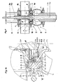
- FIG. 1 An inventive double seat valve 1 ( FIG. 1 ) is shown without a drive device which is connected via a lamp housing 6 to a valve housing 10 of the double seat valve 1 in such a way that its closing members 3, 4 via respectively associated adjusting rods 3a, 4a in a full open position H (Fig. FIGS. 3 and 3a ) or partial open positions T1, T2 ( FIGS. 5 and 5a or 4 and 4a ) can be transferred.
- the double seat valve 1 consists essentially of the valve housing 10 with a first and a second valve housing part 1a and 1b, the two independently movable closure members 3 and 4 with the respective associated adjustment rods 3a and 4a, a seat ring 2, via an inside connection opening 2c establishes a connection between the valve housing parts 1 a, 1 b, the second valve housing part 1 b connected to the drive device not shown Latemengetude 6 and also not shown, usually existing control device, the latter arranged on the side facing away from the double seat valve 1 side of the drive device is.
- the trained as a spool first closure member 3 takes place in the closed position of the double seat valve ( Figure 1, 1a ) in a formed by the connection opening 2c first seat 2a, which is designed as a cylindrical seat, sealing receiving.
- first seat seal 8 is provided on a first cylindrical end portion 3.1a of the spool 3, which is made in two parts and in its outer and, based on the display position.
- the lower region consists of a first closing member part 3.1 and its inner and, based on the display position, upper region of a second closing member part 3.2.
- the latter is arranged in an open to the second closing member 4 edge recess 3.1 b in the first closing member part 3.1 end provided first cylindrical end portion 3.1 a.
- the first seat seal 8 acts with a circumferential lateral surface 8a radially on the first seat surface 2a and with respect to the peripheral side surface 8a substantially vertically oriented, the second closing member 4 facing upper end confining surface 8b axially to one, based on the presentation position, frontal boundary surface 4b of the second closing member 4.
- the edge recess 3.1 b fixes the first seat seal 8, based on the presentation position, on the one hand immovably down.
- an annular insert part 11 is vulcanized, which, seen in cross-section, a hammer-shaped head part 11 a and a subsequent to this web 11 b.
- the latter extends substantially perpendicular to the longitudinal axis of the first closing member 3 radially inwardly and protrudes there over an inner shell-side boundary of the first seat seal 8 a piece far out.
- the web 11b undergoes a positive and non-positive clamping between the first cylindrical end part 3.1a of the first closing member part 3.1 and a second cylindrical end part 3.2a of the second closing link part 3.2 which coaxially receives the latter on the inside.
- a further measure to prevent upward displacement of the first seat seal 8 is to provide a conical end section 3.2b above the web 11b on the second cylindrical end section 3.2a, which radially widens in relation to the display position and thereby the adjacent part of the first seat seal 8 in the direction of the web 11 b and the center of the first seat seal 8 placed hammer-shaped head portion 11 a pressed.
- the edge recess 3.1 b and the conical end section 3.2 b form thus approximately a U-shaped groove for the first seat seal 8, said groove, based on the presentation position, has a center of the closing member 3 and inclined downward direction of extension.
- the joining and thus the positive and non-positive embedding of the first seat seal 8 in conjunction with its insert 11 in the first closing member 3 is effected in that the first and the second closing member part 3.1, 3.2 via a formed in the first cylindrical end portion 3.1a coaxial receiving bore 3.1 c into which engages the second cylindrical end portion 3.2a, centered coaxially with each other and bolted to each other to this guide subsequent Verschraubungsmaschine 3.1d, 3.2c.
- the formed as a seat plate second closing member 4 cooperates in the closed position of the double seat valve 1 with a second seat 2b, against which the second closing member 4 is sealed by means of a substantially axially acting second seat seal 9.
- the second seat 2b is designed conically with a slight inclination to the connection opening 2c, so that liquid can flow off automatically there.
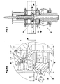
- the two closing members 3 and 4 form both in the illustrated closing and in the so-called.
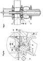
- Pickup position ( Figures 1,1a and Figures 2, 2a ) and a subsequent open position ( FIGS. 3 and 3a ) between them a leakage cavity 5, which is connected via a arranged in a tubular pressure equalizing piston 3.1e of the spool 3 drain hole 3.1g with the environment of the double seat valve 1.
- the pressure equalizing piston 3.1e is constricted in diameter in the form of a connecting part 3.1f, thus in the open position of the double seat valve 1 in the penetration region between the pressure equalizing piston 3.1 e and the first valve housing part 1a a the passage cross section of the double seat valve 1 approximately corresponding passage cross section also this position is available.
- the leakage cavity 5 is connected via a plurality of distributed over the circumference arranged connecting bores 3.2d in the second cylindrical end portion 3.2a with the drain hole 3.1g.
- the upper frontal boundary surface 8b of the first seat seal 8 is steplessly in an upper boundary surface 3.2e ( FIG. 1a ) of the second cylindrical end portion 3.2a, the latter having a small inwardly sloping slope for discharging residual liquid.
- the front end boundary surface 4b of the second closing element 4 corresponding to the upper end boundary surface 8b of the first seat seal 8 and the adjoining upper boundary surface 3.2e of the second cylindrical end part 3.2a has a course oriented almost perpendicular to the longitudinal axis of the closing elements 3, 4, wherein in FIG Pickup position ( FIG.
- a non-designated annular gap formed between the first adjusting rod 3a and the second adjusting rod 4a is sealed at its exit into the leakage cavity 5, either via a closure 7 or permeable to cleaning liquid via an annular gap nozzle 7 * ( FIG. 1a ), so that cleaning liquid, which is supplied via the annular gap from outside the double seat valve 1, is introduced via this annular nozzle 7 * on the one hand radially outward and the other with a tangential component in the leakage cavity 5, wherein the tangential component is a helical or spiral Flow generated in the leakage cavity 5.
- a first annular recess 2d is provided at the lower end of the connection opening 2c in the seat ring 2 in continuation of the first seat surface 2a ( FIG. 3a ), which merges downwardly into an annular, the connecting opening 2c radially narrowing projection 2f.
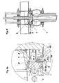
- the first annular recess 2d is dimensioned in the axial direction such that in it in the first partial open position T1 of the first closing member 3 (in FIG. FIG. 5a ), the first seat seal 8 is placed such that between the first seat seal 8 and the adjacent seat ring 2, a sufficient passage gap for a zoom out of the first valve housing part 1a first seat cleaning flow R1 is available.
- a second annular recess 2e which is oriented essentially parallel to the longitudinal axis of the closing members 3, 4, adjoins the second seat surface 2b radially on the outside (FIG. FIG. 3a ), in which the outer lateral surface of the second closing member 4, which has there a second outer diameter d4, partially engages and there forms a circumferential ring gap with a second radial gap S2 ( FIG. 2a ).
- FIG. 2a is further clarified, is formed between the first seat 2a and the inside adjacent first cylindrical end portion 3.1 a, which has a first outer diameter d3, a circumferential annular gap with a third radial gap S1 *.
- a further circumferential annular gap with a first radial gap S1 is achieved when the first closing member 3 has been transferred to its first partial open position T1 ( FIG. 5a ) in which it forms this circumferential annular gap between the first outer diameter d3 of the first cylindrical end portion 3.1a and the annular projection 2f having a first inner diameter D3.
- the first and second valve housing parts 1a, 1b are connected to one another via a connecting means 12, in the present case via a so-called clamping ring connection ( Figures 1, 1a ).
- a connecting means 12 in the present case via a so-called clamping ring connection ( Figures 1, 1a ).
- an unmarked cover is connected to the first valve housing part 1a in order to seal it downwards.
- a corresponding connection exists between the upper valve housing part 1 a and the lamp housing. 6
- the full opening stroke H of the double-seat valve 1 is initiated by the fact that the first closing member 3 is displaced over the first adjusting rod 3a in the direction of the second closing member 4, comes to rest thereon ( FIG. 2a ; shown pickup position) and in the further opening movement, the second closing member 4 also transferred to an open position ( FIGS. 3 and 3a ).
- the pick-up position results in the above-described circumferential annular gap, which has the third radial gap S1 *.
- the latter can be dimensioned sufficiently large, since this circumferential annular gap does not have any fluidic function, so that there is no reason to expect any touching or "seizing" in this area.
- FIGS. 3 and 3a show the full opening stroke H (full open position) of the double seat valve 1.
- a flow flow Q can either pass from the first valve housing part 1a to the second valve body part 1b or vice versa on the way through the connection opening 2c.
- the leakage cavity 5 is hermetically sealed due to the axial sealing function of the first seat seal 8 relative to the second closing member 4 to the environment, in this case the interior of the second valve body part 1 b, so that no fluid from the latter can get into the leakage cavity 5.
- the first seat cleaning flow R1 from the first valve housing part 1a can now be brought to the first seat seal 8 which can be flowed around in the first annular recess 2d via the first throttle gap D1, so that a cleaning of this area and of the adjoining first seat surface 2a is provided.
- the first seat cleaning flow R1 then passes via the leakage cavity 5, the connection bores 3.2d and the subsequent drainage bore 3.1g finally into the environment of the double seat valve 1.
Landscapes
- Engineering & Computer Science (AREA)
- General Engineering & Computer Science (AREA)
- Mechanical Engineering (AREA)
- Lift Valve (AREA)
- Superconductors And Manufacturing Methods Therefor (AREA)
- Fluid-Driven Valves (AREA)
- Details Of Valves (AREA)
Claims (12)
- Soupape à double siège (1) comprenant deux éléments de fermeture (3, 4) mobiles l'un par rapport à l'autre et disposés en série, qui évitent dans la position de fermeture de la soupape à double siège (1) le débordement de fluides d'une partie de cage de soupape (1a, 1b) à une autre, qui délimitent non seulement dans la position de fermeture, mais aussi dans la position d'ouverture, une cavité de fuite (5) entre eux, cette cavité présentant au moins une voie de communication avec l'environnement de la soupape à double siège, dans la position de fermeture de la soupape à double siège (1) un premier élément de fermeture (3), configuré comme un piston coulissant, avec un segment d'extrémité qui est équipé d'un premier joint de siège (8) logé de façon étanche contre une première surface d'appui (2a) dans un orifice de communication (2c) reliant les parties de cage de soupape (1a, 1b) entre elles, et au cours de son mouvement d'ouverture, en direction d'un axe vertical en cours d'utilisation, vient en appui étanche contre le second élément de fermeture (4) configuré comme plateau d'appui avec un second joint de siège (9), et le second élément de fermeture est également transféré lors du mouvement d'ouverture ultérieur dans la position d'ouverture, moyennant quoi le premier joint de siège (8) devient étanche radialement par rapport à la première surface d'appui (2a) conçue comme surface d'appui cylindrique, et axialement par rapport au second élément de fermeture (4), moyennant quoi le premier joint de siège (8) est disposé dans un évidement marginal (3.1b) ouvert vers le second élément de fermeture (4) dans le premier élément de fermeture (3), moyennant quoi une surface de délimitation (8b) frontale supérieure dirigée vers le second élément de fermeture (4) du premier joint de siège (8) se poursuit dans une surface de délimitation supérieure (3.2e) du premier élément de fermeture (3), et la surface de délimitation frontale supérieure (8b) du premier joint de siège (8) est orientée essentiellement perpendiculairement à la surface d'appui cylindrique (2a), et moyennant quoi le second joint de siège (9) est adjacent lors du contact avec une seconde surface d'appui (2b) associée, vu dans la direction radiale, directement côté extérieur à la surface d'appui cylindrique (2a), et, vu axialement, directement à l'extrémité de la surface d'appui cylindrique (2a), et est dimensionné de telle sorte que son bord dirigé vers la seconde surface d'appui (2b), vu radialement, s'étend vers l'intérieur au-dessus de la surface d'appui cylindrique (2a),
caractérisée en ce que• la surface de délimitation (8b) frontale supérieure du premier joint de siège (8), se poursuivant dans la surface de délimitation supérieure (3.2e) du premier élément de fermeture (3), présente une distance axiale plus courte par rapport au second élément de fermeture (4) que la surface de délimitation supérieure (3.2e) du premier élément de fermeture (3),• et une surface de délimitation (4b) frontale du second élément de fermeture (4), dirigée vers le premier élément de fermeture (3) entourée par la surface d'appui cylindrique (2a) dans la zone de l'étendue radiale de la surface de délimitation frontale supérieure (8b) du premier joint de siège (8), possède une inclinaison ascendante très faible orientée vers l'axe central du second élément de fermeture (4). - Soupape à double siège selon la revendication 1,
caractérisée en ce que
le premier joint de siège (8) est encastré dans l'évidement marginal (3.1b) par complémentarité de forme et de force. - Soupape à double siège selon les revendications 1 ou 2,
caractérisée en ce
qu'une pièce d'insertion (11) est encastrée dans le premier joint de siège (8). - Soupape à double siège selon la revendication 3,
caractérisée en ce que
la pièce d'insertion (11), vu dans la direction radiale, ressort du premier joint de siège (8) vers l'intérieur sous la forme d'une nervure (11b). - Soupape à double siège selon les revendications 3 ou 4,
caractérisée en ce que
la pièce d'insertion (11) est configurée dans une partie s'étendant axialement comme une pièce de tête en forme de marteau (11a). - Soupape à double siège selon les revendications 4 ou 5,
caractérisée en ce que
le premier élément de fermeture (3) est conçu en deux parties sous la forme d'une première partie d'élément de fermeture (3.1) principalement radiale sur le côté externe et d'une seconde partie d'élément de fermeture (3.2) principalement radiale sur le côté interne, la nervure (11b) entre les parties d'élément de fermeture (3.1, 3.2) est fixée dans la direction axiale, et la première partie d'élément de fermeture (3.1) forme l'évidement marginal (3.1b) d'un côté, et la seconde partie d'élément de fermeture (3.2) forme l'évidement marginal (3.1b) de l'autre côté de la nervure (11b). - Soupape à double siège selon la revendication 6,
caractérisée en ce que
la nervure (11b) reçoit à travers la seconde partie d'élément de fermeture (3.2), vu radialement, un appui sur le côté interne. - Soupape à double siège selon les revendications 6 ou 7,
caractérisée en ce que
les parties d'élément de fermeture (3.1, 3.2) sont dirigées coaxialement les unes aux autres via un ajustement cylindrique (3.1c, 3.2a) en direction de l'axe longitudinal du premier élément de fermeture (3), et sont vissées les unes aux autres par un vissage (3.1 d, 3.2c) rattaché à ce guidage. - Soupape à double siège selon une des revendications 1 à 8,
caractérisée en ce que
l'évidement marginal (3.1b) est configuré essentiellement en forme de V dans la zone détournée du second élément de fermeture (4), et en effet de telle sorte que le joint de siège (8) correspondant à cette zone, vu radialement, se rétrécit en conséquence de l'intérieur vers l'extérieur. - Soupape à double siège selon une des revendications 6 à 9,
caractérisée en ce que
la seconde partie d'élément de fermeture (3.2) dirigée vers le second élément de fermeture (4) présente un segment d'extrémité conique (3.2b) qui comprime le premier joint de siège (8) adjacent, de telle sorte que celui-ci se rétrécit en conséquence de l'extérieur vers l'intérieur dans cette zone, vu radialement. - Soupape à double siège selon une des revendications 1 à 10,
caractérisée en ce que
les deux éléments de fermeture (3,4) peuvent être déplacés indépendamment l'un de l'autre, par une course partielle (T1, T2) respectivement d'une largeur de fente, dans une position de nettoyage de siège à des fins de rinçage de leurs surfaces d'appui (2a, 2b),
et en ce que les éléments de fermeture (3, 4) présentent respectivement un rebord (d3, d4) cylindrique disposé contre ceux-ci qui forme avec un segment (D3, D4) associé respectivement de l'orifice de communication (2c) une fente d'étranglement (D1, D2), et en ce que cette dernière est disposée respectivement sur le côté d'arrivée de fluide du joint de siège (8, 9) résultant de l'écoulement de nettoyage du siège (R1, R2). - Soupape à double siège selon la revendication 11,
caractérisée en ce
qu'un premier évidement (2d) annulaire est prévu entre la surface d'appui cylindrique (2a) du premier élément de fermeture (3) et la surface délimitant côté cage la fente d'étranglement (D1) avec un premier diamètre interne (D3).
Applications Claiming Priority (2)
| Application Number | Priority Date | Filing Date | Title |
|---|---|---|---|
| DE102004015799 | 2004-03-29 | ||
| PCT/EP2005/002966 WO2005098287A1 (fr) | 2004-03-29 | 2005-03-19 | Soupape a double siege |
Publications (2)
| Publication Number | Publication Date |
|---|---|
| EP1730430A1 EP1730430A1 (fr) | 2006-12-13 |
| EP1730430B1 true EP1730430B1 (fr) | 2008-10-01 |
Family
ID=34962764
Family Applications (1)
| Application Number | Title | Priority Date | Filing Date |
|---|---|---|---|
| EP05716246A Active EP1730430B1 (fr) | 2004-03-29 | 2005-03-19 | Soupape a double siege |
Country Status (6)
| Country | Link |
|---|---|
| EP (1) | EP1730430B1 (fr) |
| AT (1) | ATE409825T1 (fr) |
| DE (1) | DE502005005540D1 (fr) |
| DK (1) | DK1730430T3 (fr) |
| ES (1) | ES2315850T3 (fr) |
| WO (1) | WO2005098287A1 (fr) |
Families Citing this family (3)
| Publication number | Priority date | Publication date | Assignee | Title |
|---|---|---|---|---|
| ATE529672T1 (de) * | 2007-10-30 | 2011-11-15 | Gea Tuchenhagen Gmbh | Sitzreinigungsfähiges doppelsitzventil und verfahren zur reinigung des sitzreinigungsfähigen doppelsitzventils |
| DE102010030298A1 (de) * | 2010-06-21 | 2011-12-22 | Krones Aktiengesellschaft | Mehrteiliger Ventilteller |
| DE102010030300A1 (de) * | 2010-06-21 | 2011-12-22 | Krones Aktiengesellschaft | Doppelsitzventil und Abdichtung eines Doppelsitzventils |
Family Cites Families (5)
| Publication number | Priority date | Publication date | Assignee | Title |
|---|---|---|---|---|
| DE3109002C2 (de) | 1981-03-10 | 1986-12-18 | Holstein Und Kappert Gmbh, 4600 Dortmund | Doppelsitzventil mit Leckkontrolle und zwei unabhängig voneinander bewegbaren Ventiltellern |
| DE3242947A1 (de) | 1982-11-20 | 1984-05-24 | Holstein Und Kappert Gmbh, 4600 Dortmund | Doppelsitzventil mit zwei ventiltellern |
| DE4332109C2 (de) * | 1993-09-22 | 1995-07-06 | Tuchenhagen Otto Gmbh | Vorrichtung zum leckagefreien Schalten eines Doppelsitzventils |
| EP0819876B1 (fr) | 1996-07-15 | 2002-12-11 | Toyo Stainless Steel Industries Co., Ltd. | Soupape à double siège |
| FR2791753B1 (fr) * | 1999-04-02 | 2001-09-21 | Defontaine | Vanne a clapet perfectionne a joint en elastomere |
-
2005
- 2005-03-19 ES ES05716246T patent/ES2315850T3/es active Active
- 2005-03-19 EP EP05716246A patent/EP1730430B1/fr active Active
- 2005-03-19 AT AT05716246T patent/ATE409825T1/de not_active IP Right Cessation
- 2005-03-19 DK DK05716246T patent/DK1730430T3/da active
- 2005-03-19 WO PCT/EP2005/002966 patent/WO2005098287A1/fr active IP Right Grant
- 2005-03-19 DE DE502005005540T patent/DE502005005540D1/de active Active
Also Published As
| Publication number | Publication date |
|---|---|
| ES2315850T3 (es) | 2009-04-01 |
| DK1730430T3 (da) | 2009-02-09 |
| ATE409825T1 (de) | 2008-10-15 |
| DE502005005540D1 (de) | 2008-11-13 |
| WO2005098287A1 (fr) | 2005-10-20 |
| EP1730430A1 (fr) | 2006-12-13 |
Similar Documents
| Publication | Publication Date | Title |
|---|---|---|
| DE69213528T2 (de) | Keimfreie Ventilkonstruktion | |
| EP1952046B1 (fr) | Soupape a double siege | |
| CH693649A5 (de) | Tellerventildichtungsvorrichtung. | |
| DE69025344T2 (de) | Zylinder-Kolben-Vorrichtung | |
| EP2232111B1 (fr) | Dispositif d'entrainement d'une soupape a double siege presentant une fonction de nettoyage du siege | |
| EP1648583B1 (fr) | Ensemble filtre a huile et element filtrant | |
| DE4307437C2 (de) | Anschlußvorrichtungen für Rohrleitungen | |
| DE202007018740U1 (de) | Doppelsitzventil | |
| EP2252813B1 (fr) | Soupape à double siège, permettant le nettoyage des sièges, avec un dispositif de nettoyage pour une traversée du boîtier | |
| DE10319061B4 (de) | Durchflussregelventil | |
| EP1730430B1 (fr) | Soupape a double siege | |
| EP2861898B1 (fr) | Soupape à double siège permettant un nettoyage des sièges | |
| EP0983455B1 (fr) | Soupape a double siege de commutation sans fuites | |
| EP0447675B1 (fr) | Ressort à gaz à longueur réglable | |
| DE4236464C2 (de) | Leckagefreies Ventil | |
| EP2203667B1 (fr) | Soupape a double siege avec possibilite de nettoyage de siege et procede de nettoyage de cette soupape | |
| DE4332109C2 (de) | Vorrichtung zum leckagefreien Schalten eines Doppelsitzventils | |
| DE60207783T2 (de) | Schnellverbindungskupplung | |
| DE3306382C2 (fr) | ||
| DE102005016932B3 (de) | Verfahren zur Verformung einer Sitzdichtung eines Ventils im Bereich der Sitzfläche im Zuge des Schließhubes und Sitzdichtung zur Durchführung des Verfahrens | |
| EP3658803B1 (fr) | Soupape à double siège ayant une membrane | |
| DE3625805C2 (fr) | ||
| WO1997007880A1 (fr) | Dispositif pour retirer une matiere en vrac contenue dans un recipient sous pression | |
| DE69807598T2 (de) | Ventil für Druckbehälter | |
| EP0082922B1 (fr) | Raccord rapide à fermeture |
Legal Events
| Date | Code | Title | Description |
|---|---|---|---|
| PUAI | Public reference made under article 153(3) epc to a published international application that has entered the european phase |
Free format text: ORIGINAL CODE: 0009012 |
|
| 17P | Request for examination filed |
Effective date: 20060825 |
|
| AK | Designated contracting states |
Kind code of ref document: A1 Designated state(s): AT BE BG CH CY CZ DE DK EE ES FI FR GB GR HU IE IS IT LI LT LU MC NL PL PT RO SE SI SK TR |
|
| 17Q | First examination report despatched |
Effective date: 20070130 |
|
| DAX | Request for extension of the european patent (deleted) | ||
| GRAP | Despatch of communication of intention to grant a patent |
Free format text: ORIGINAL CODE: EPIDOSNIGR1 |
|
| GRAL | Information related to payment of fee for publishing/printing deleted |
Free format text: ORIGINAL CODE: EPIDOSDIGR3 |
|
| GRAS | Grant fee paid |
Free format text: ORIGINAL CODE: EPIDOSNIGR3 |
|
| GRAA | (expected) grant |
Free format text: ORIGINAL CODE: 0009210 |
|
| AK | Designated contracting states |
Kind code of ref document: B1 Designated state(s): AT BE BG CH CY CZ DE DK EE ES FI FR GB GR HU IE IS IT LI LT LU MC NL PL PT RO SE SI SK TR |
|
| REG | Reference to a national code |
Ref country code: GB Ref legal event code: FG4D Free format text: NOT ENGLISH |
|
| REG | Reference to a national code |
Ref country code: CH Ref legal event code: EP |
|
| REG | Reference to a national code |
Ref country code: IE Ref legal event code: FG4D Free format text: LANGUAGE OF EP DOCUMENT: GERMAN |
|
| REF | Corresponds to: |
Ref document number: 502005005540 Country of ref document: DE Date of ref document: 20081113 Kind code of ref document: P |
|
| REG | Reference to a national code |
Ref country code: SE Ref legal event code: TRGR |
|
| REG | Reference to a national code |
Ref country code: CH Ref legal event code: NV Representative=s name: ISLER & PEDRAZZINI AG |
|
| REG | Reference to a national code |
Ref country code: DK Ref legal event code: T3 |
|
| PG25 | Lapsed in a contracting state [announced via postgrant information from national office to epo] |
Ref country code: SI Free format text: LAPSE BECAUSE OF FAILURE TO SUBMIT A TRANSLATION OF THE DESCRIPTION OR TO PAY THE FEE WITHIN THE PRESCRIBED TIME-LIMIT Effective date: 20081001 |
|
| REG | Reference to a national code |
Ref country code: ES Ref legal event code: FG2A Ref document number: 2315850 Country of ref document: ES Kind code of ref document: T3 |
|
| REG | Reference to a national code |
Ref country code: IE Ref legal event code: FD4D |
|
| PG25 | Lapsed in a contracting state [announced via postgrant information from national office to epo] |
Ref country code: LT Free format text: LAPSE BECAUSE OF FAILURE TO SUBMIT A TRANSLATION OF THE DESCRIPTION OR TO PAY THE FEE WITHIN THE PRESCRIBED TIME-LIMIT Effective date: 20081001 Ref country code: BG Free format text: LAPSE BECAUSE OF FAILURE TO SUBMIT A TRANSLATION OF THE DESCRIPTION OR TO PAY THE FEE WITHIN THE PRESCRIBED TIME-LIMIT Effective date: 20090101 |
|
| PGFP | Annual fee paid to national office [announced via postgrant information from national office to epo] |
Ref country code: DK Payment date: 20090324 Year of fee payment: 5 |
|
| PG25 | Lapsed in a contracting state [announced via postgrant information from national office to epo] |
Ref country code: FI Free format text: LAPSE BECAUSE OF FAILURE TO SUBMIT A TRANSLATION OF THE DESCRIPTION OR TO PAY THE FEE WITHIN THE PRESCRIBED TIME-LIMIT Effective date: 20081001 Ref country code: PT Free format text: LAPSE BECAUSE OF FAILURE TO SUBMIT A TRANSLATION OF THE DESCRIPTION OR TO PAY THE FEE WITHIN THE PRESCRIBED TIME-LIMIT Effective date: 20090302 Ref country code: IS Free format text: LAPSE BECAUSE OF FAILURE TO SUBMIT A TRANSLATION OF THE DESCRIPTION OR TO PAY THE FEE WITHIN THE PRESCRIBED TIME-LIMIT Effective date: 20090201 Ref country code: PL Free format text: LAPSE BECAUSE OF FAILURE TO SUBMIT A TRANSLATION OF THE DESCRIPTION OR TO PAY THE FEE WITHIN THE PRESCRIBED TIME-LIMIT Effective date: 20081001 |
|
| PG25 | Lapsed in a contracting state [announced via postgrant information from national office to epo] |
Ref country code: RO Free format text: LAPSE BECAUSE OF FAILURE TO SUBMIT A TRANSLATION OF THE DESCRIPTION OR TO PAY THE FEE WITHIN THE PRESCRIBED TIME-LIMIT Effective date: 20081001 Ref country code: EE Free format text: LAPSE BECAUSE OF FAILURE TO SUBMIT A TRANSLATION OF THE DESCRIPTION OR TO PAY THE FEE WITHIN THE PRESCRIBED TIME-LIMIT Effective date: 20081001 Ref country code: IE Free format text: LAPSE BECAUSE OF FAILURE TO SUBMIT A TRANSLATION OF THE DESCRIPTION OR TO PAY THE FEE WITHIN THE PRESCRIBED TIME-LIMIT Effective date: 20081001 |
|
| PLBE | No opposition filed within time limit |
Free format text: ORIGINAL CODE: 0009261 |
|
| STAA | Information on the status of an ep patent application or granted ep patent |
Free format text: STATUS: NO OPPOSITION FILED WITHIN TIME LIMIT |
|
| PG25 | Lapsed in a contracting state [announced via postgrant information from national office to epo] |
Ref country code: CZ Free format text: LAPSE BECAUSE OF FAILURE TO SUBMIT A TRANSLATION OF THE DESCRIPTION OR TO PAY THE FEE WITHIN THE PRESCRIBED TIME-LIMIT Effective date: 20081001 |
|
| PGFP | Annual fee paid to national office [announced via postgrant information from national office to epo] |
Ref country code: IT Payment date: 20090326 Year of fee payment: 5 Ref country code: SE Payment date: 20090318 Year of fee payment: 5 |
|
| 26N | No opposition filed |
Effective date: 20090702 |
|
| BERE | Be: lapsed |
Owner name: TUCHENHAGEN G.M.B.H. Effective date: 20090331 |
|
| PG25 | Lapsed in a contracting state [announced via postgrant information from national office to epo] |
Ref country code: SK Free format text: LAPSE BECAUSE OF FAILURE TO SUBMIT A TRANSLATION OF THE DESCRIPTION OR TO PAY THE FEE WITHIN THE PRESCRIBED TIME-LIMIT Effective date: 20081001 |
|
| PG25 | Lapsed in a contracting state [announced via postgrant information from national office to epo] |
Ref country code: MC Free format text: LAPSE BECAUSE OF NON-PAYMENT OF DUE FEES Effective date: 20090331 |
|
| PGFP | Annual fee paid to national office [announced via postgrant information from national office to epo] |
Ref country code: CH Payment date: 20090403 Year of fee payment: 5 |
|
| GBPC | Gb: european patent ceased through non-payment of renewal fee |
Effective date: 20090319 |
|
| NLV4 | Nl: lapsed or anulled due to non-payment of the annual fee |
Effective date: 20091001 |
|
| REG | Reference to a national code |
Ref country code: FR Ref legal event code: ST Effective date: 20091130 |
|
| PG25 | Lapsed in a contracting state [announced via postgrant information from national office to epo] |
Ref country code: BE Free format text: LAPSE BECAUSE OF NON-PAYMENT OF DUE FEES Effective date: 20090331 Ref country code: NL Free format text: LAPSE BECAUSE OF NON-PAYMENT OF DUE FEES Effective date: 20091001 |
|
| PG25 | Lapsed in a contracting state [announced via postgrant information from national office to epo] |
Ref country code: GB Free format text: LAPSE BECAUSE OF NON-PAYMENT OF DUE FEES Effective date: 20090319 Ref country code: FR Free format text: LAPSE BECAUSE OF NON-PAYMENT OF DUE FEES Effective date: 20091123 |
|
| REG | Reference to a national code |
Ref country code: ES Ref legal event code: FD2A Effective date: 20090320 |
|
| PG25 | Lapsed in a contracting state [announced via postgrant information from national office to epo] |
Ref country code: AT Free format text: LAPSE BECAUSE OF NON-PAYMENT OF DUE FEES Effective date: 20090319 |
|
| PG25 | Lapsed in a contracting state [announced via postgrant information from national office to epo] |
Ref country code: ES Free format text: LAPSE BECAUSE OF NON-PAYMENT OF DUE FEES Effective date: 20090320 |
|
| PG25 | Lapsed in a contracting state [announced via postgrant information from national office to epo] |
Ref country code: GR Free format text: LAPSE BECAUSE OF FAILURE TO SUBMIT A TRANSLATION OF THE DESCRIPTION OR TO PAY THE FEE WITHIN THE PRESCRIBED TIME-LIMIT Effective date: 20090102 |
|
| REG | Reference to a national code |
Ref country code: CH Ref legal event code: PL |
|
| EUG | Se: european patent has lapsed | ||
| REG | Reference to a national code |
Ref country code: DK Ref legal event code: EBP |
|
| PG25 | Lapsed in a contracting state [announced via postgrant information from national office to epo] |
Ref country code: CH Free format text: LAPSE BECAUSE OF NON-PAYMENT OF DUE FEES Effective date: 20100331 Ref country code: LI Free format text: LAPSE BECAUSE OF NON-PAYMENT OF DUE FEES Effective date: 20100331 |
|
| PG25 | Lapsed in a contracting state [announced via postgrant information from national office to epo] |
Ref country code: IT Free format text: LAPSE BECAUSE OF NON-PAYMENT OF DUE FEES Effective date: 20100319 |
|
| PG25 | Lapsed in a contracting state [announced via postgrant information from national office to epo] |
Ref country code: LU Free format text: LAPSE BECAUSE OF NON-PAYMENT OF DUE FEES Effective date: 20090319 Ref country code: DK Free format text: LAPSE BECAUSE OF NON-PAYMENT OF DUE FEES Effective date: 20100331 |
|
| PG25 | Lapsed in a contracting state [announced via postgrant information from national office to epo] |
Ref country code: HU Free format text: LAPSE BECAUSE OF FAILURE TO SUBMIT A TRANSLATION OF THE DESCRIPTION OR TO PAY THE FEE WITHIN THE PRESCRIBED TIME-LIMIT Effective date: 20090402 |
|
| PG25 | Lapsed in a contracting state [announced via postgrant information from national office to epo] |
Ref country code: TR Free format text: LAPSE BECAUSE OF FAILURE TO SUBMIT A TRANSLATION OF THE DESCRIPTION OR TO PAY THE FEE WITHIN THE PRESCRIBED TIME-LIMIT Effective date: 20081001 |
|
| PG25 | Lapsed in a contracting state [announced via postgrant information from national office to epo] |
Ref country code: CY Free format text: LAPSE BECAUSE OF FAILURE TO SUBMIT A TRANSLATION OF THE DESCRIPTION OR TO PAY THE FEE WITHIN THE PRESCRIBED TIME-LIMIT Effective date: 20081001 |
|
| PG25 | Lapsed in a contracting state [announced via postgrant information from national office to epo] |
Ref country code: SE Free format text: LAPSE BECAUSE OF NON-PAYMENT OF DUE FEES Effective date: 20100320 |
|
| PGFP | Annual fee paid to national office [announced via postgrant information from national office to epo] |
Ref country code: DE Payment date: 20240331 Year of fee payment: 20 |