EP1729401A2 - Electric linear drive with end of stroke sensor - Google Patents
Electric linear drive with end of stroke sensor Download PDFInfo
- Publication number
- EP1729401A2 EP1729401A2 EP06010898A EP06010898A EP1729401A2 EP 1729401 A2 EP1729401 A2 EP 1729401A2 EP 06010898 A EP06010898 A EP 06010898A EP 06010898 A EP06010898 A EP 06010898A EP 1729401 A2 EP1729401 A2 EP 1729401A2
- Authority
- EP
- European Patent Office
- Prior art keywords
- housing
- electrolinear
- spindle
- drive according
- plunger
- Prior art date
- Legal status (The legal status is an assumption and is not a legal conclusion. Google has not performed a legal analysis and makes no representation as to the accuracy of the status listed.)
- Withdrawn
Links
Images


Classifications
-
- H—ELECTRICITY
- H02—GENERATION; CONVERSION OR DISTRIBUTION OF ELECTRIC POWER
- H02K—DYNAMO-ELECTRIC MACHINES
- H02K7/00—Arrangements for handling mechanical energy structurally associated with dynamo-electric machines, e.g. structural association with mechanical driving motors or auxiliary dynamo-electric machines
- H02K7/06—Means for converting reciprocating motion into rotary motion or vice versa
-
- F—MECHANICAL ENGINEERING; LIGHTING; HEATING; WEAPONS; BLASTING
- F16—ENGINEERING ELEMENTS AND UNITS; GENERAL MEASURES FOR PRODUCING AND MAINTAINING EFFECTIVE FUNCTIONING OF MACHINES OR INSTALLATIONS; THERMAL INSULATION IN GENERAL
- F16H—GEARING
- F16H25/00—Gearings comprising primarily only cams, cam-followers and screw-and-nut mechanisms
- F16H25/18—Gearings comprising primarily only cams, cam-followers and screw-and-nut mechanisms for conveying or interconverting oscillating or reciprocating motions
- F16H25/20—Screw mechanisms
- F16H25/2015—Means specially adapted for stopping actuators in the end position; Position sensing means
-
- H—ELECTRICITY
- H02—GENERATION; CONVERSION OR DISTRIBUTION OF ELECTRIC POWER
- H02K—DYNAMO-ELECTRIC MACHINES
- H02K11/00—Structural association of dynamo-electric machines with electric components or with devices for shielding, monitoring or protection
- H02K11/20—Structural association of dynamo-electric machines with electric components or with devices for shielding, monitoring or protection for measuring, monitoring, testing, protecting or switching
- H02K11/21—Devices for sensing speed or position, or actuated thereby
-
- H—ELECTRICITY
- H02—GENERATION; CONVERSION OR DISTRIBUTION OF ELECTRIC POWER
- H02K—DYNAMO-ELECTRIC MACHINES
- H02K2211/00—Specific aspects not provided for in the other groups of this subclass relating to measuring or protective devices or electric components
- H02K2211/03—Machines characterised by circuit boards, e.g. pcb
-
- H—ELECTRICITY
- H02—GENERATION; CONVERSION OR DISTRIBUTION OF ELECTRIC POWER
- H02K—DYNAMO-ELECTRIC MACHINES
- H02K5/00—Casings; Enclosures; Supports
- H02K5/04—Casings or enclosures characterised by the shape, form or construction thereof
- H02K5/10—Casings or enclosures characterised by the shape, form or construction thereof with arrangements for protection from ingress, e.g. water or fingers
Definitions
- the invention relates to an electric linear drive with limit switch according to the preamble of claim 1.
- Such electrolinear drives can be used as adjusting devices for adjusting moving parts with considerable forces manifold, such as for smoke and heat exhaust ventilation flaps, especially as components of smoke and heat ventilation systems, ventilation wings, ventilation blinds, skylights and belts with ventilation function, Butterfly valves for pipe and duct ventilation devices, windows and doors.
- Prior art electroluminescent actuators include a torque tube which is displaced by an electric motor via gear means including a spindle which is rotated by the electric motor and engages a spindle nut fixedly connected to the torque tube. Since the electric linear drive can be exposed to the weather or otherwise moisture influences, moisture-sensitive electrical components are arranged sealed in a housing of the linear drive to the outside. The seal of the housing interior is, however, in particular, as a result of the led out of the housing and the thrust pipe produced by him and the spindle nut when actuated in the housing suction at best to achieve with elaborate structural means or seals.
- a known from practice electrolinear drive with limit in two end positions of a push tube of the type mentioned comprises a divided by a central bearing plate into two housing sections housing.
- an electric motor and a load shedding board are arranged with electrical components for the end stop of the electric motor.
- the limit stop is to shut off the electric motor when the torque tube has reached one of its possible end positions and to avoid mechanical overloading of the electric linear drive and / or elements actuated by it as well as thermal overload of the electric motor when the torque tube is "on block". drove.
- limit switch boards are electrically connected to the load control board of the motor controller in the first housing section via leads passing through an opening in the bearing plate.
- the central bearing plate does not seal the two housing sections against moisture. It serves to accommodate in a ball bearing and a spindle sleeve in which an end-side pin of the spindle is rotatably mounted, the is in communication with a transmission output of the engine.
- the spindle is connected in a force-transmitting manner in the second housing section via the displaceably guided spindle nut to the torque tube, which protrudes out of the second housing section through an end-side housing cover.
- the housing cover receives a scraper, through which the torque tube is passed. - With the scraper in the frontal housing cover and by further sealing measures the entire housing interior, which comprises the first housing portion and the second housing portion to be sealed to the outside against moisture, but this is not always achieved permanently for the reasons mentioned above.
- the present invention is therefore an object of the invention to improve the sealing of the housing interior, which receives electrical parts to the outside against moisture with uncomplicated design means.
- the essence of the invention is that not the entire housing of the electric linear drive is sealed to the outside, but only the first housing portion which receives the electric motor, said first portion is sealed against the second housing portion against moisture, namely in the region of a storage of Spindle, with which the torque tube is actuated, as well as on a plunger unit which transmits in End eins Silveren the torque tube a limited shift in the first housing section, in which the limit switches are arranged, with which the electric motor is automatically switched off in one of the end positions of the torque tube.
- the second housing section which essentially requires the spindle and the optionally actuated by a spindle nut torque tube includes, as far as the latter is not extended, not to be protected from the outside tight against the ingress of moisture.
- the inventive design of the electric linear drive is additionally achieved that due to the displacement of the limit switch from the second housing section in which they would normally be operated, in the first housing section, the assembly of the entirety of the electrical components of the electric linear drive can be simplified by the limit switches, for example are arranged on a circuit board of a printed circuit in the first housing section, which accommodates further components for the load shutdown of the electric motor, see claim 11.
- the plunger unit with spring-loaded centering in combination which are suitable to center outside of the end positions of the thrust tube not mitschobene with this plunger unit in a starting position.
- This centering is thus in view of the fact that the second portion of the plunger unit in the second housing portion, in which optionally the torque tube and the spindle nut are located, is suitable to be mitschoben only in End too Kunststoffen the torque tube with this.
- the plunger unit is thus not permanently fixedly coupled to the torque tube or the spindle nut, which can facilitate the production of the linear drive, because it allows the plunger unit to limit shift by a defined distance can be moved, which is independent of the mutual distance of the end positions of the torque tube.
- a compact design of the spring-loaded centering means has the features of claim 3, that it comprises a compression spring between two sliding discs and two lock washers which are mounted at a distance from each other on the ram unit that they include the loaded by the compression spring sliding discs that the sliding discs be in the initial position of the plunger unit under the load of the compression spring to housing fixed stops, and that each of the two sliding was suitable to be moved with one of the two lock washers together with the plunger unit against the load by the compression spring of the adjacent stop away.
- the centering ensure the centering of the plunger unit in its initial position and on the other hand allow a displacement of the plunger unit for actuating the limit switch when the torque tube or the spindle nut is in one of its end position ranges and accordingly entrains the plunger unit.
- a first of the two stops formed by a recess in the bearing plate which at least partially receives one of the two sliding discs and beyond can be designed so that it slidingly guides this sliding disk, while a second of the two Stops at a fixed distance from the first stop in the second housing portion is arranged.
- the spring-loaded centering arranged in recesses of the bearing plate and a voltage applied to her back plate, the ram unit through the bearing plate and the counter-plate concentrically extends to the spring-loaded centering, by a in the Counter-plate arranged seal which seals the recesses of the bearing plate and the counter-plate relative to the second housing portion.
- a spindle nut in a conventional manner to a housing inner end of the torque tube is slidably mounted and guided together with the push tube, the second portion of the ram unit is suitably designed so that it is moved along with the spindle nut when the torque tube is pushed by the spindle nut in one of its two end position ranges.
- the spindle nut having a sliding nut with a lug which is adapted to move the second portion of the plunger unit in end positions of the torque tube with.
- the ram unit can have drivers or stops, one of which in each case comes into contact with the shoulder of the sliding nut in one of the end positions of the torque tube.
- the bearing plate between the first housing portion and the second housing portion receive a spindle bearing, a seal of the spindle bearing and a seal of the plunger unit.
- this plunger unit has a displaceable in the second housing portion sheet metal part with two spaced-apart angled stops, which are adapted to be taken from the spindle nut in End eins Colouren the spindle nut or the torque tube, and a with the Sheet metal part in solid compound plunger, which extends sealed against the second housing portion in the first housing portion.
- This ram unit can be manufactured with simple conventional tools, namely by punching the sheet metal part, bending the angled stops and turning the plunger. This embodiment is particularly suitable for smaller quantities of the electric linear drive with end stop.
- the displaceable sheet metal part can be performed according to claim 1 3 easily in a housing-fixed groove in the second housing section.
- a second embodiment of the ram unit according to claim 14 requires the production of a special profile bar.
- This is slidably mounted to the second housing section. In their ends screws are screwed with laterally protruding screw heads to the spindle nut in End eins Colouren the spindle nut or the To be taken along push tube.
- the profile bar is connected to a plunger in a fixed connection, which extends through the bearing plate and possibly the voltage applied to her back plate and is suitable with its first portion in the first housing portion to actuate the limit switch.
- profile bars requires special manufacturing facilities to form a continuous profile. From this then profile bars of the desired length can be easily cut off, after which they can be provided with frontal screws for driving through the spindle nut. By cutting the profile bar to length from a longer profile, electropower drives with limit stops at different end positions of the torque tube can be produced efficiently.
- the profile bar is formed with the features that it has a lower cross-sectionally approximately cylindrical part with a threaded bore, from the top of an extension is formed with a continuous threaded hole, which receives the two screws at the end, that the extension of two inside
- the guide means formed in the second housing section are encompassed, and in that a groove is formed at the bottom from the approximately cylindrical part and rests on a web formed from the second housing section.
- the groove and the web formed from the second housing portion serve in conjunction with the molded from the second housing portion guide lugs for exact guidance of the profile bar in the second housing portion.
- the plunger and the profile bar made of aluminum, which can be processed well and allows a relatively low-mass design of the electric linear drive.
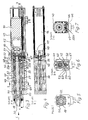
- FIGS. 1 and 2 two housing sections of a first embodiment of an electrolinear drive are designated 1 and 2.
- the two housing sections 1 and 2 are separated according to the detailed illustrated first embodiment in Figure 2 by a bearing plate 3.
- an electric motor 4 with a gear 5 and a load shedding board 6 are arranged in the first housing section 1.
- the limit switches 8, 9 are located in the first housing section 1.
- the first housing section 1 is sealed to the outside with respect to moisture, in particular with a cable seal 1 2, through which a connecting cable 13 is inserted into the first housing section.
- first housing portion 1 is also relative to the second housing portion 2, which includes a spindle 14 and a thrust tube 15 substantially, at the inner end of a spindle nut 1 6 sits, in which engages the spindle.
- An outer end of the spindle is mounted in the torque tube by means of a centering ring 17, see Figure 2.
- An outer end of the torque tube is guided by a frontal housing cover 18 to the outside and penetrates this purpose a scraper 19 in the lid.
- a pipe plug 20 closes the torque tube 1 5 at its outer end and serves to connect the torque tube with a part to be adjusted by this.
- An inner end of the spindle 14 is formed as a pin and is received by a spindle bolt 21 which is mounted by means of a ball bearing 22 in a spindle sleeve 23 which is sealed with a seal 24 in the bearing plate 3.
- the inner end of the spindle is connected to an unspecified output of the transmission 5 for transmitting a torque.
- an elongated ram unit generally designated 25 is. It consists essentially of a plunger 26 with a fixed thereto in the second housing section 2 slidable strip-shaped sheet metal part 27.
- the elongated plunger unit 25 thus extends substantially parallel to the torque tube 1 5 in the second housing section 2 and through the bearing plate 3 therethrough in the first housing portion 1, in which a contour is formed on the plunger end for actuating the actuating elements 10, 11 of the limit switches 8, 9.
- the plate member 27 connected to the plunger 26 has in the second housing portion angled stops 28, 29 which are suitable in End eins Colouren the torque tube 15 and the associated spindle nut 16, to be actuated by the spindle nut 16, see Figure 2.
- angled stops 28, 29 which are suitable in End eins Buffaloen the torque tube 15 and the associated spindle nut 16, to be actuated by the spindle nut 16, see Figure 2.
- the spindle nut 16 interacts directly with drivers 28a, 29a, which correspond to the angled stops 28, 29 in Figure 2.
- the ram unit 25 is centered in a central position when the angled stops 28, 29 and drivers 28a, 29a are not loaded or shifted, with spring-loaded centering, which are generally designated 32, see Figure 2, in a middle Centered starting position, which is shown in Figure 1.
- the ram unit 25 is near its inner or right end position.
- the spring-loaded centering means 32 comprise a compression spring 33 which presses apart two sliding disks 34, 35 displaceable on the plunger 26, specifically until it rests against each other at a mutual distance arranged locking washers 36, 37, which sit firmly in not designated grooves of the plunger 26.
- angled stops 28, 29 it is noted that these must not be prepared as separate parts and fixed to the sheet metal part 27, but also can be formed integrally formed directly from the sheet metal part.
- the motor 4 which pushes the torque tube 15 by means of the spindle 14 to the outside, is thereby switched off via the electronics of the load shedding board 6, which can also be referred to as Endabschaltplatine.
- the motor can then be turned on externally in the opposite direction of rotation, whereby the torque tube is retracted and the plunger 26 is returned under the action of the compression spring 33 back into its mean starting position.
- the second embodiment of the electric linear drive according to Figures 3 to 7 differs from the first embodiment, in particular according to Figure 2, once in that between a first housing portion 40 and a second housing portion 41 except a bearing plate 42 on the bearing plate on the side of the second Housing portion 41 lying counter-plate 43 are arranged.
- the electric motor 44 with a gear 45 and a circuit board 46 are arranged, which carries a load shedding electronics and limit switches 47, 48.
- the second housing portion 41 in turn includes the majority of a spindle 49, the unnamed pin is connected to an output of the transmission 45 in torque transmitted connection and is mounted via a spindle bolt 50 in a ball bearing 51 and a spindle sleeve 52 which is arranged in the counter-plate ,
- the spindle 49 engages a spindle nut 53 which is attached to an inner end of a push tube 54.
- a sliding nut 53 a On the spindle nut 53 sits a sliding nut 53 a, which is suitable to cooperate with a generally designated 55 ram unit.
- the ram unit 55 differs from the first embodiment:
- the ram unit 55 although in turn comprises a plunger 55 a, of which one end, which is located in the first housing portion 40 is designed so that there are unnamed actuators of the limit switch 47 , 48 can press.
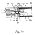
- This plunger extends through the bearing plate 42 and through the counter-plate 43 into the second housing portion 41, through a seal 56, which is arranged here in the counter-plate 43.
- one end of the plunger 55a is screwed into a sliding in the second housing portion 41 profile rod 57, in a threaded bore 58, see Figure 4.
- the cross-section of the profile bar 57 which expediently consists of aluminum, results from FIG. 6: It can be seen that the profile bar 57 has a lower cross-sectionally approximately cylindrical part 59, through which the threaded bore 58 for the ram passes centrally. At its lowest point, the cylindrical part 59 has a groove 60 which rests on a web 61 formed from the second housing portion 41 inside. Upwardly extends from the cylindrical portion 59, a narrower extension 62 which is encompassed by guide lugs 72, 73, which are formed from the second housing portion 41. In the extension 62, a continuous threaded hole 63 is provided, which receives at each end of the profile rod 57 a screwed screw 64 and 65 with laterally projecting screw head.
- the screw heads are arranged so that they are taken from the spindle nut 53 and sitting on the spindle nut slide nut 53a in End eins Buffaloen the torque tube 54 and the spindle nut 53, including the sliding nut not designated depressions on both sides of a lug 66.
- centering 67 are in frictional connection, which are constructed substantially like the centering means 32 of Figure 2, which is why matching components are provided with the same reference numerals.
- the centering means 67 are illustrated in FIG. 4a. It can be seen that a stop of a left sliding washer 35 a is formed by a recess in the counter-plate 43.
- the centering means 67 are arranged in a chamber 68, which is formed on the one hand from the bearing plate 42 and on the other hand from the counter plate 44.
- the chamber 68 is sealed relative to the second housing portion 41 by the seal 56 in the backing plate 43.
- the counter-plate 43 also receives a seal 69 of the spindle sleeve 52.
- the first housing portion 40 is protected against the ingress of moisture, even if the scraper 19 and a further seal 70 on a housing cover 71 through which an outer end portion of the torque tube 54 is guided with the pipe plug 20, see Figure 3, should only cause an incomplete seal.
- the centering 67 including the compression spring 33a centered in their middle position ram unit 55 is a reliable two-sided limit in end positions of the torque tube, which can be determined flexibly and accurately by the length and arrangement of the profile bar and screwed into them without changing the mounting position of the limit switch.
Abstract
Description
Die Erfindung betrifft einen Elektrolinearantrieb mit Endabschaltung nach dem Oberbegriff des Anspruchs 1.The invention relates to an electric linear drive with limit switch according to the preamble of claim 1.
Derartige Elektrolinearantriebe können als Stellvorrichtungen zum Verstellen beweglicher Teile mit erheblichen Kräften vielfältig eingesetzt werden, wie für Rauch- und Wärmeabzüge, Lüftungsklappen, insbesondere als Bestandteilen von RWA-Anlagen (Rauch- und Wärmeabzugsanlagen), Lüftungsflügel, Lüftungsjalousien, Lichtkuppeln und -bänder mit Lüftungsfunktion, Stellklappen für Rohr- und Kanallüftungsgeräte, Fenster und Türen.Such electrolinear drives can be used as adjusting devices for adjusting moving parts with considerable forces manifold, such as for smoke and heat exhaust ventilation flaps, especially as components of smoke and heat ventilation systems, ventilation wings, ventilation blinds, skylights and belts with ventilation function, Butterfly valves for pipe and duct ventilation devices, windows and doors.
Zum Stand der Technik gehörende Elektrolinearantriebe umfassen ein Schubrohr, das durch einen Elektromotor über Getriebemittel einschließlich einer Spindel, die durch den Elektromotor in Drehung versetzt wird und in eine mit dem Schubrohr fest verbundene Spindelmutter eingreift, verschoben wird. Da der Elektrolinearantrieb der Witterung oder in sonstiger Weise Feuchtigkeitseinflüssen ausgesetzt sein kann, sind feuchteempfindliche elektrische Komponenten in einem Gehäuse des Linearantriebs nach außen abgedichtet angeordnet. Die Abdichtung des Gehäuseinneren ist jedoch, insbesondere infolge des aus dem Gehäuse herausgeführten Schubrohrs und des von ihm und der Spindelmutter bei Betätigung in dem Gehäuse erzeugten Sogs allenfalls mit aufwendigen konstruktiven Mitteln bzw. Dichtungen zu erreichen.Prior art electroluminescent actuators include a torque tube which is displaced by an electric motor via gear means including a spindle which is rotated by the electric motor and engages a spindle nut fixedly connected to the torque tube. Since the electric linear drive can be exposed to the weather or otherwise moisture influences, moisture-sensitive electrical components are arranged sealed in a housing of the linear drive to the outside. The seal of the housing interior is, however, in particular, as a result of the led out of the housing and the thrust pipe produced by him and the spindle nut when actuated in the housing suction at best to achieve with elaborate structural means or seals.
Im einzelnen umfaßt ein aus der Praxis bekannter Elektrolinearantrieb mit Endabschaltung in zwei Endstellungen eines Schubrohrs der eingangs genannten Gattung ein durch eine zentrale Lagerplatte in zwei Gehäuseabschnitte unterteiltes Gehäuse. In dem ersten Gehäuseabschnitt sind ein Elektromotor und eine Lastabschaltungsplatine mit elektrischen Bauteilen zur Endabschaltung des Elektromotors angeordnet. Die Endabschaltung dient dazu, den Elektromotor abzuschalten, wenn das Schubrohr eine seiner möglichen Endstellungen erreicht hat, und um eine mechanische Überlastung des Elektrolinearantriebs und/oder der von ihr betätigten Elemente sowie eine thermische Überlastung des Elektromotors zu vermeiden, wenn das Schubrohr "auf Block" gefahren ist. Zur Abschaltung des Elektromotors, wenn das Schubrohr in eine seiner beiden Endstellungen gefahren ist, dienen zwei Endschalter, die in dem zweiten Gehäuseabschnitt auf Endschalterplatinen so angeordnet sind, daß ihre Betätigungselemente direkt durch die Spindelmutter bzw. eine auf die Spindelmutter aufgebrachte Schiebemutter betätigt werden, wenn diese in eine ihrer beiden Endstellungen verschoben wird. Die Endschalterplatinen stehen über Leitungen, die durch eine Öffnung in der Lagerplatte hindurchgeführt sind, mit der Lastabschaltungsplatine der Motorsteuerung in dem ersten Gehäuseabschnitt in elektrischer Verbindung.In detail, a known from practice electrolinear drive with limit in two end positions of a push tube of the type mentioned comprises a divided by a central bearing plate into two housing sections housing. In the first housing portion, an electric motor and a load shedding board are arranged with electrical components for the end stop of the electric motor. The limit stop is to shut off the electric motor when the torque tube has reached one of its possible end positions and to avoid mechanical overloading of the electric linear drive and / or elements actuated by it as well as thermal overload of the electric motor when the torque tube is "on block". drove. To shut off the electric motor, when the torque tube has moved into one of its two end positions, serve two limit switches, which are arranged in the second housing section on limit switch boards so that their actuators are actuated directly by the spindle nut or a nut applied to the spindle nut sliding nut when this is moved to one of its two end positions. The limit switch boards are electrically connected to the load control board of the motor controller in the first housing section via leads passing through an opening in the bearing plate.
Die zentrale Lagerplatte dichtet die beiden Gehäuseabschnitte nicht gegen Feuchte ab. Sie dient dazu, in ein Kugellager und eine Spindelhülse aufzunehmen, in der ein endseitiger Zapfen der Spindel drehbar gelagert ist, der mit einem Getriebeausgang des Motors in Verbindung steht. Die Spindel ist in dem zweiten Gehäuseabschnitt über die verschiebbar geführte Spindelmutter mit dem Schubrohr kraftübertragend verbunden, welches durch einen stirnseitigen Gehäusedeckel aus dem zweiten Gehäuseabschnitt herausragt. Der Gehäusedeckel nimmt einen Abstreifer auf, durch den das Schubrohr hindurchgeführt ist. - Mit dem Abstreifer in dem stirnseitigen Gehäusedeckel und durch weitere Dichtungsmaßnahmen soll das gesamte Gehäuseinnere, welches den ersten Gehäuseabschnitt und den zweiten Gehäuseabschnitt umfaßt, nach außen gegen Feuchtigkeit abgedichtet werden, was aber aus den weiter oben genannten Gründen nicht immer dauerhaft erreicht wird.The central bearing plate does not seal the two housing sections against moisture. It serves to accommodate in a ball bearing and a spindle sleeve in which an end-side pin of the spindle is rotatably mounted, the is in communication with a transmission output of the engine. The spindle is connected in a force-transmitting manner in the second housing section via the displaceably guided spindle nut to the torque tube, which protrudes out of the second housing section through an end-side housing cover. The housing cover receives a scraper, through which the torque tube is passed. - With the scraper in the frontal housing cover and by further sealing measures the entire housing interior, which comprises the first housing portion and the second housing portion to be sealed to the outside against moisture, but this is not always achieved permanently for the reasons mentioned above.
Der vorliegenden Erfindung liegt daher die Aufgabe zugrunde, die Abdichtung des Gehäuseinneren, welches elektrische Teile aufnimmt, nach außen gegen Feuchte mit unkomplizierten konstruktiven Mitteln zu verbessern.The present invention is therefore an object of the invention to improve the sealing of the housing interior, which receives electrical parts to the outside against moisture with uncomplicated design means.
Diese Aufgabe wird mit einem Elektrolinearantrieb gelöst, der die in Anspruch 1 angegebenen Merkmale aufweist.This object is achieved with an electric linear drive having the features specified in claim 1.
Der Kern der Erfindung besteht darin, daß nicht das gesamte Gehäuse des Elektrolinearantriebs nach außen abgedichtet wird, sondern nur der erste Gehäuseabschnitt, der den Elektromotor aufnimmt, wobei dieser erste Abschnitt auch gegenüber dem zweiten Gehäuseabschnitt gegen Feuchte abgedichtet ist, nämlich im Bereich einer Lagerung der Spindel, mit der das Schubrohr betätigt wird, sowie an einer Stößeleinheit, die in Endstellungsbereichen des Schubrohrs eine begrenzte Verschiebung in den ersten Gehäuseabschnitt überträgt, in dem hier die Endschalter angeordnet sind, mit denen der Elektromotor in einer der Endstellungen des Schubrohrs selbsttätig abgeschaltet wird. Somit braucht der zweite Gehäuseabschnitt, der im wesentlichen die Spindel und das von ihr gegebenenfalls über eine Spindelmutter betätigte Schubrohr einschließt, soweit letzteres nicht ausgefahren ist, nach außen nicht dicht gegen das Eindringen von Feuchtigkeit geschützt zu sein.The essence of the invention is that not the entire housing of the electric linear drive is sealed to the outside, but only the first housing portion which receives the electric motor, said first portion is sealed against the second housing portion against moisture, namely in the region of a storage of Spindle, with which the torque tube is actuated, as well as on a plunger unit which transmits in Endstellungsbereichen the torque tube a limited shift in the first housing section, in which the limit switches are arranged, with which the electric motor is automatically switched off in one of the end positions of the torque tube. Thus, the second housing section, which essentially requires the spindle and the optionally actuated by a spindle nut torque tube includes, as far as the latter is not extended, not to be protected from the outside tight against the ingress of moisture.
Durch die erfindungsgemäße Ausbildung des Elektrolinearantriebs wird zusätzlich erreicht, daß infolge der Verlagerung der Endschalter aus dem zweiten Gehäuseabschnitt, in dem sie normalerweise zu betätigen wären, in den ersten Gehäuseabschnitt die Montage der Gesamtheit der elektrischen Komponenten des Elektrolinearantriebs vereinfacht werden kann, indem die Endschalter beispielsweise auf einer Platine einer gedruckten Schaltung in dem ersten Gehäuseabschnitt angeordnet sind, die weitere Bauteile für die Lastabschaltung bzw. Endabschaltung des Elektromotors aufnimmt, siehe Anspruch 11.The inventive design of the electric linear drive is additionally achieved that due to the displacement of the limit switch from the second housing section in which they would normally be operated, in the first housing section, the assembly of the entirety of the electrical components of the electric linear drive can be simplified by the limit switches, for example are arranged on a circuit board of a printed circuit in the first housing section, which accommodates further components for the load shutdown of the electric motor, see
Um eine exakte Lastabschaltung bzw. Endabschaltung durch die Stößeleinheit zu erreichen, steht gemäß Anspruch 2 die Stößeleinheit mit federbelasteten Zentriermitteln in Verbindung, welche geeignet sind, die außerhalb der Endstellungsbereiche des Schubrohrs nicht mit diesem mitverschobene Stößeleinheit in einer Ausgangsposition zu zentrieren. Diese Zentrierung erfolgt somit im Hinblick darauf, daß der zweite Abschnitt der Stößeleinheit in dem zweiten Gehäuseabschnitt, in dem sich gegebenenfalls das Schubrohr und die Spindelmutter befinden, geeignet ist, nur in Endstellungsbereichen des Schubrohrs mit diesem mitverschoben zu werden. Die Stößeleinheit ist also nicht mit dem Schubrohr bzw. der Spindelmutter ständig fest gekoppelt, was die Herstellung des Linearantriebs erleichtern kann, weil damit die Stößeleinheit zur Endabschaltung um eine definierte Strecke verschoben werden kann, die unabhängig von dem gegenseitigen Abstand der Endstellungen des Schubrohrs ist.In order to achieve an exact load shutdown or end stop by the plunger unit, according to claim 2, the plunger unit with spring-loaded centering in combination, which are suitable to center outside of the end positions of the thrust tube not mitschobene with this plunger unit in a starting position. This centering is thus in view of the fact that the second portion of the plunger unit in the second housing portion, in which optionally the torque tube and the spindle nut are located, is suitable to be mitschoben only in Endstellungsbereichen the torque tube with this. The plunger unit is thus not permanently fixedly coupled to the torque tube or the spindle nut, which can facilitate the production of the linear drive, because it allows the plunger unit to limit shift by a defined distance can be moved, which is independent of the mutual distance of the end positions of the torque tube.
Eine kompakte Ausbildung der federbelasteten Zentriermittel weist die Merkmale des Anspruchs 3 auf, daß sie eine Druckfeder zwischen zwei Gleitscheiben und zwei Sicherungsscheiben umfaßt, die so im Abstand zueinander an der Stößeleinheit befestigt sind, daß sie die durch die Druckfeder belasteten Gleitscheiben einschließen, daß die Gleitscheiben in der Ausgangsposition der Stößeleinheit unter der Belastung durch die Druckfeder an gehäusefesten Anschlägen anliegen, und daß jede der beiden Gleitscheiben geeignet ist, mit je einem der beiden Sicherungsscheiben zusammen mit der Stößeleinheit entgegen der Belastung durch die Druckfeder von dem benachbarten Anschlag weg verschoben zu werden. Somit gewährleisten die Zentriermittel die Zentrierung der Stößeleinheit in deren Ausgangsposition und lassen andererseits eine Verschiebung der Stößeleinheit zur Betätigung der Endschalter zu, wenn sich das Schubrohr bzw. die Spindelmutter in einer ihrer Endstellungsbereichen befindet und dementsprechend die Stößeleinheit mitnimmt.A compact design of the spring-loaded centering means has the features of
Zur weiterhin kompakten Ausbildung und Kraftübertragung zwischen der Stößeleinheit und den federbelasteten Zentriermitteln ohne Verkantung der Stößeleinheit ist diese konzentrisch in den Zentriermitteln angeordnet.For further compact design and power transmission between the plunger unit and the spring-loaded centering without tilting the plunger unit it is arranged concentrically in the centering.
In einer Ausführungsform des Elektrolinearantriebs wird gemäß Anspruch 5 ein erster der beiden Anschläge durch eine Vertiefung in der Lagerplatte gebildet, die eine der beiden Gleitscheiben wenigstens teilweise aufnimmt und darüber hinaus so ausgebildet sein kann, daß sie diese Gleitscheibe verschiebbar führt, während ein zweiter der beiden Anschläge in festem Abstand zu dem ersten Anschlag in dem zweiten Gehäuseabschnitt angeordnet ist.In one embodiment of the electric linear drive according to
Um Feuchtigkeitseinflüsse auf die federbelasteten Zentriermittel zu vermeiden sind in einer zweiten Ausführung die federbelasteten Zentriermittel in Ausnehmungen der Lagerplatte und einer an ihr anliegenden Gegenplatte angeordnet, wobei die Stößeleinheit durch die Lagerplatte und die Gegenplatte konzentrisch zu den federbelasteten Zentriermitteln hindurchreicht, und zwar durch eine in der Gegenplatte angeordnete Dichtung, welche die Ausnehmungen der Lagerplatte und der Gegenplatte gegenüber dem zweiten Gehäuseabschnitt abdichtet.In order to avoid the influence of moisture on the spring-loaded centering in a second embodiment, the spring-loaded centering arranged in recesses of the bearing plate and a voltage applied to her back plate, the ram unit through the bearing plate and the counter-plate concentrically extends to the spring-loaded centering, by a in the Counter-plate arranged seal which seals the recesses of the bearing plate and the counter-plate relative to the second housing portion.
Wenn gemäß Anspruch 7 eine Spindelmutter in an sich bekannter Weise an einem Gehäuseinneren Ende des Schubrohrs drehfest angeordnet ist und zusammen mit dem Schubrohr verschiebbar geführt ist, ist der zweite Abschnitt der Stößeleinheit zweckmäßig so ausgebildet, daß er mit der Spindelmutter mitverschoben wird, wenn das Schubrohr durch die Spindelmutter in einen seiner beiden Endstellungsbereiche geschoben wird.If according to claim 7, a spindle nut in a conventional manner to a housing inner end of the torque tube is slidably mounted and guided together with the push tube, the second portion of the ram unit is suitably designed so that it is moved along with the spindle nut when the torque tube is pushed by the spindle nut in one of its two end position ranges.
Hierzu kann die Spindelmutter eine Schiebemutter mit einem Ansatz aufweisen, der geeignet ist, den zweiten Abschnitt der Stößeleinheit in Endstellungsbereichen des Schubrohrs mit zu verschieben. Wie weiter unten ausgeführt wird, kann hierzu die Stößeleinheit Mitnehmer oder Anschläge aufweisen, von denen jeweils einer in einem der Endstellungsbereiche des Schubrohrs an dem Ansatz der Schiebemutter zur Anlage gelangt.For this purpose, the spindle nut having a sliding nut with a lug which is adapted to move the second portion of the plunger unit in end positions of the torque tube with. As will be explained below, for this purpose, the ram unit can have drivers or stops, one of which in each case comes into contact with the shoulder of the sliding nut in one of the end positions of the torque tube.
In einer Ausführungsform nach Anspruch 9 kann die Lagerplatte zwischen dem ersten Gehäuseabschnitt und dem zweiten Gehäuseabschnitt ein Spindellager, eine Dichtung des Spindellagers sowie eine Dichtung der Stößeleinheit aufnehmen. Diese Ausführungsform ist konstruktiv unkompliziert.In an embodiment according to claim 9, the bearing plate between the first housing portion and the second housing portion receive a spindle bearing, a seal of the spindle bearing and a seal of the plunger unit. This embodiment is structurally straightforward.
In einer alternativen Ausführungsform gemäß Anspruch 10 kann aber auch die Gegenplatte, die an der Lagerplatte anliegt, die Dichtungen der Spindel und der Stößeleinheit aufnehmen, während das Spindellager, wie bei der ersten Ausführungsform, in der Lagerplatte angeordnet ist. Die letztgenannte Ausführungsform hat den Vorteil, daß die federbelasteten Zentriermittel, wie oben erwähnt, in Ausnehmungen der Lagerplatte und der Gegenplatte gegen Feuchte geschützt sind.In an alternative embodiment according to
In einer ersten Ausführungsform der Stößeleinheit gemäß Anspruch 12 weist diese ein in dem zweiten Gehäuseabschnitt verschiebbares Blechteil mit zwei im Abstand zueinander abgewinkelten Anschlägen auf, die geeignet sind, von der Spindelmutter in Endstellungsbereichen der Spindelmutter bzw. des Schubrohrs mitgenommen zu werden, sowie einen mit dem Blechteil in fester Verbindung stehenden Stößel, welcher gegenüber dem zweiten Gehäuseabschnitt abgedichtet in den ersten Gehäuseabschnitt hineinreicht. - Diese Stößeleinheit kann mit einfachen üblichen Werkzeugen gefertigt werden, nämlich durch Stanzen des Blechteils, Biegen der abgewinkelten Anschläge sowie Drehen des Stößels. Diese Ausführungsform eignet sich insbesondere für kleinere Stückzahlen des Elektrolinearantriebs mit Endabschaltung.In a first embodiment of the plunger unit according to
Das verschiebbare Blechteil kann gemäß Anspruch 1 3 einfach in einer gehäusefesten Nut in den zweiten Gehäuseabschnitt geführt werden.The displaceable sheet metal part can be performed according to claim 1 3 easily in a housing-fixed groove in the second housing section.
Demgegenüber setzt eine zweite Ausführungsform der Stößeleinheit nach Anspruch 14 die Fertigung einer speziellen Profilstange voraus. Diese wird dem zweiten Gehäuseabschnitt verschiebbar montiert. In ihre Enden sind Schrauben mit seitlich überstehenden Schraubköpfen geschraubt, um von der Spindelmutter in Endstellungsbereichen der Spindelmutter bzw. des Schubrohrs mitgenommen zu werden. Die Profilstange steht mit einem Stößel in fester Verbindung, welcher durch die Lagerplatte und ggf. die an ihr anliegende Gegenplatte hindurchreicht und mit seinem ersten Abschnitt in dem ersten Gehäuseabschnitt geeignet ist, die Endschalter zu betätigen. Die Herstellung der Profilstangen setzt zwar spezielle Fertigungseinrichtungen voraus, um ein fortlaufendes Profil auszuformen. Von diesem können dann Profilstangen der gewünschten Länge einfach abgeschnitten werden, wonach sie mit stirnseitigen Schrauben zur Mitnahme durch die Spindelmutter versehen werden können. Es können durch Ablängen der Profilstange von einem längeren Profil wahlweise Elektrolinearantriebe mit Endabschaltungen bei verschiedenen Endpositionen des Schubrohrs rationell hergestellt werden.In contrast, a second embodiment of the ram unit according to
Im einzelnen ist die Profilstange mit den Merkmalen ausgebildet, daß sie einen unteren im Querschnitt annähernd zylindrischen Teil mit einer Gewindebohrung aufweist, aus dem oben ein Fortsatz mit einem durchgängigen Gewindeloch ausgeformt ist, welches endseitig die beiden Schrauben aufnimmt, daß der Fortsatz von zwei innen aus dem zweiten Gehäuseabschnitt ausgeformten Führungsansätzen umgriffen wird, und daß unten aus dem annähernd zylindrischen Teil eine Nut ausgeformt ist, die auf einem aus dem zweiten Gehäuseabschnitt ausgeformten Steg aufliegt. Die Nut und der aus dem zweiten Gehäuseabschnitt ausgeformte Steg dienen in Verbindung mit den aus dem zweiten Gehäuseabschnitt ausgeformten Führungsansätzen zur exakten Führung der Profilstange in dem zweiten Gehäuseabschnitt.In particular, the profile bar is formed with the features that it has a lower cross-sectionally approximately cylindrical part with a threaded bore, from the top of an extension is formed with a continuous threaded hole, which receives the two screws at the end, that the extension of two inside The guide means formed in the second housing section are encompassed, and in that a groove is formed at the bottom from the approximately cylindrical part and rests on a web formed from the second housing section. The groove and the web formed from the second housing portion serve in conjunction with the molded from the second housing portion guide lugs for exact guidance of the profile bar in the second housing portion.
Zweckmäßig bestehen der Stößel und die Profilstange aus Aluminium, welches gut bearbeitet werden kann und eine verhältnismäßig massearme Ausführung des Elektrolinearantriebs erlaubt.Suitably, the plunger and the profile bar made of aluminum, which can be processed well and allows a relatively low-mass design of the electric linear drive.
Ausführungsbeispiele der Erfindung werden im folgenden anhand einer Zeichnung mit acht Figuren beschrieben, woraus sich weitere vorteilhafte Merkmale der Erfindung ergeben können. Es zeigen:
- Figur 1
- eine erste Ausführungsform des Elektrolinearantriebs in einem geschnittenen Gehäuse als schematische Seiten-ansicht,
- Figur 2
- die erste Ausführungsform des Linearantriebs gemäß Figur 1, detaillierter, in einem Längsschnitt,
Figur 3- eine zweite Ausführungsform des Elektrolinearantriebs in einem Längsschnitt,
Figur 4- einen Schnitt durch die zweite Ausführungsform gemäß
Figur 3 in der Schnittebene D-D, - Figur 4a
- in größerer Darstellung ein Detail des Schnitts gemäß
Figur 4 im Bereich von Zentriermitteln, Figur 5- eine Ansicht auf die Vorderseite der zweiten Ausführungsform in Richtung E,
Figur 6- einen Querschnitt durch die zweite Ausführungsform in der Schnittebene B-B und
- Figur 7
- einen Querschnitt durch die zweite Ausführungsform in der Schnittebene C-C.
- FIG. 1
- a first embodiment of the electric linear drive in a cut housing as a schematic side view,
- FIG. 2
- the first embodiment of the linear drive according to Figure 1, in more detail, in a longitudinal section,
- FIG. 3
- a second embodiment of the electric linear drive in a longitudinal section,
- FIG. 4
- a section through the second embodiment according to Figure 3 in the sectional plane DD,
- FIG. 4a
- in a larger representation a detail of the section according to FIG. 4 in the region of centering means,
- FIG. 5
- a view of the front of the second embodiment in the direction E,
- FIG. 6
- a cross section through the second embodiment in the sectional plane BB and
- FIG. 7
- a cross section through the second embodiment in the sectional plane CC.
In den Figuren 1 und 2 sind zwei Gehäuseabschnitte einer ersten Ausführungsform eines Elektrolinearantriebs mit 1 und 2 bezeichnet. Die beiden Gehäuseabschnitte 1 und 2 sind gemäß der detaillierten dargestellten ersten Ausführungsform in Figur 2 durch eine Lagerplatte 3 getrennt.In FIGS. 1 and 2, two housing sections of a first embodiment of an electrolinear drive are designated 1 and 2. The two housing sections 1 and 2 are separated according to the detailed illustrated first embodiment in Figure 2 by a
In dem ersten Gehäuseabschnitt 1 sind ein Elektromotor 4 mit einem Getriebe 5 sowie eine Lastabschaltungsplatine 6 angeordnet. Auf der Lastabschaltungsplatine 6, siehe Figuren 2 und 3, bzw. auf einer gesonderten Platine 7 neben der Lastabschaltungsplatine 6 gemäß Figur 1 sind zwei Endschalter 8, 9 angeordnet, die Betätigungselemente 10, 11 aufweisen. Die Endschalter 8, 9 befinden sich in dem ersten Gehäuseabschnitt 1.In the first housing section 1, an
Der erste Gehäuseabschnitt 1 ist nach außen gegenüber Feuchte abgedichtet, insbesondere mit einer Kabelabdichtung 1 2, durch die ein Anschlußkabel 13 in den ersten Gehäuseabschnitt eingeführt wird.The first housing section 1 is sealed to the outside with respect to moisture, in particular with a cable seal 1 2, through which a connecting
Abgedichtet ist der erste Gehäuseabschnitt 1 auch gegenüber dem zweiten Gehäuseabschnitt 2, der im wesentlichen eine Spindel 14 und ein Schubrohr 15 einschließt, an dessen innerem Ende eine Spindelmutter 1 6 sitzt, in die die Spindel eingreift. Ein äußeres Ende der Spindel ist in dem Schubrohr mittels eines Zentrierrings 17 gelagert, siehe Figur 2. Ein äußeres Ende des Schubrohrs ist durch einen stirnseitigen Gehäusedeckel 18 nach außen geführt und durchdringt hierzu einen Abstreifer 19 in dem Deckel. Ein Rohrstopfen 20 verschließt das Schubrohr 1 5 an seinem äußeren Ende und dient zur Verbindung des Schubrohrs mit einem durch dieses zu verstellenden Teil.Sealed the first housing portion 1 is also relative to the second housing portion 2, which includes a
Ein inneres Ende der Spindel 14 ist als Zapfen ausgebildet und wird von einem Spindelbolzen 21 aufgenommen, der mittels eines Kugellagers 22 in einer Spindelhülse 23 gelagert ist, die mit einer Dichtung 24 abgedichtet in der Lagerplatte 3 sitzt. In dem Spindelbolzen 21 ist das innere Ende der Spindel mit einem nicht bezeichneten Ausgang des Getriebes 5 zur Übertragung eines Drehmoments verbunden.An inner end of the
Zur Betätigung der beiden Endschalter 8 und 9 in dem ersten Gehäuseabschnitt 1 dient eine längliche Stößeleinheit, die allgemein mit 25 bezeichnet ist. Sie besteht im wesentlichen aus einem Stößel 26 mit einem mit diesem in dem zweiten Gehäuseabschnitt 2 fest verbundenen verschiebbaren streifenförmigen Blechteil 27. Die längliche Stößeleinheit 25 erstreckt sich somit im wesentlichen parallel zu dem Schubrohr 1 5 in dem zweiten Gehäuseabschnitt 2 sowie durch die Lagerplatte 3 hindurch in dem ersten Gehäuseabschnitt 1, in dem eine Kontur an dem Stößelende zur Betätigung der Betätigungselemente 10, 11 der Endschalter 8, 9 ausgeformt ist. Das mit dem Stößel 26 verbundene Blechteil 27 weist in dem zweiten Gehäuseabschnitt abgewinkelte Anschläge 28, 29 auf, die in Endstellungsbereichen des Schubrohrs 15 bzw. der mit ihm verbundenen Spindelmutter 16 geeignet sind, von der Spindelmutter 16 betätigt zu werden, siehe Figur 2. Hierzu sitzt auf der Spindelmutter 16 eine Gleitmutter 30 mit einem Ansatz 31. - In der vereinfachten ersten Ausführungsform gemäß Figur 1 wirkt die Spindelmutter 16 direkt mit Mitnehmern 28a, 29a zusammen, welche den abgewinkelten Anschlägen 28, 29 in Figur 2 entsprechen.To actuate the two
Aus Figur 2 ist ersichtlich, daß die abgewinkelten Anschläge 28, 29 unten in eine Nut 31 hineinreichen, in der sie parallel zur Spindel bzw. zum Schubrohr verschiebbar sind. Die Spindelmutter 16 und die auf ihr sitzende Gleitmutter 30 sind ebenfalls in dieser Richtung verschiebbar.From Figure 2 it can be seen that the angled stops 28, 29 extend into the bottom of a
Die Stößeleinheit 25 ist zu ihrer Zentrierung in einer mittleren Ausgangsposition, wenn die abgewinkelten Anschläge 28, 29 bzw. Mitnehmer 28a, 29a nicht belastet bzw. verschoben sind, mit federbelasteten Zentriermitteln, die allgemein mit 32 bezeichnet sind, siehe Figur 2, in einer mittleren Ausgangsstellung zentriert, die in Figur 1 dargestellt ist. In Figur 2 befindet sich die Stößeleinheit 25 nahe ihrer inneren bzw. rechten Endstellung. Die federbelasteten Zentriermittel 32 umfassen eine Druckfeder 33, die zwei auf dem Stößel 26 verschiebbare Gleitscheiben 34, 35 auseinanderdrückt, und zwar bis zur Anlage an im gegenseitigen Abstand zueinander angeordneten Sicherungsscheiben 36, 37, die fest in nicht bezeichneten Nuten des Stößels 26 sitzen.The
Zu den abgewinkelten Anschlägen 28, 29 wird bemerkt, daß diese nicht als separate Teile hergestellt und auf dem Blechteil 27 befestigt sein müssen, sondern auch direkt aus dem Blechteil einstückig ausgeformt sein können.The angled stops 28, 29 it is noted that these must not be prepared as separate parts and fixed to the
In der in Figur 2 dargestellten Position der Stößeleinheit liegt in einer nicht bezeichneten Ausnehmung der Lagerplatte 3 verschiebbar geführte rechte Gleitscheibe 34 an einer Stirnseite der Ausnehmung an, an der die Ausnehmung einen Anschlag bildet. Im festen Abstand zu dem Anschlag ist in dem zweiten Gehäuseabschnitt 2 ein weiterer Anschlag angeordnet, der mit 38 bezeichnet ist und an dem die linke Gleitscheibe 35 anliegt. Der Stößel 26 ist durch die Gleitscheiben 34, 35, die Sicherungsscheiben 36, 37 und die Druckfeder 33 konzentrisch hindurchgeführt. Zur Abdichtung des ersten Gehäuseabschnitts 1 gegenüber dem zweiten Gehäuseabschnitt 2 im Bereich dieser Durchführung dient eine Dichtung 39 in der Lagerplatte 3.In the position of the plunger unit shown in Figure 2 is located in an unspecified recess of the
In den in Figuren 1 und 2 dargestellten Positionen der Stößeleinheit 25 wird keiner der beiden Endschalter 8, 9 durch sein Betätigungselement 10 bzw. 11 betätigt, da sich nur ein nicht bezeichneter verjüngter Abschnitt des Stößels 26 bei diesen Betätigungselementen befindet. Diese Einstellung hält an, bis beispielsweise der abgewinkelte Anschlag 28 bei einer Verschiebung des Schubrohrs 15 nach außen in dessen Endstellungsbereich durch den Ansatz 31 der Gleitmutter mitgenommen wird. Dementsprechend drückt die Sicherungsscheibe 37 gegen die Gleitscheibe 34 und diese aus der Ausnehmung der Lagerplatte 3 heraus und betätigt mit dem konischen Ende in dem ersten Abschnitt des Stößels 26 das Betätigungselement 11 des Endschalters 8. Der Motor 4, der das Schubrohr 15 mittels der Spindel 14 nach außen schiebt, wird dadurch über die Elektronik der Lastabschaltungsplatine 6, die auch als Endabschaltplatine bezeichnet werden kann, abgeschaltet. Der Motor kann dann in entgegengesetzter Drehrichtung extern wieder eingeschaltet werden, womit das Schubrohr eingezogen wird und der Stößel 26 unter der Wirkung der Druckfeder 33 wieder in seine mittlere Ausgangsstellung zurückgestellt wird. - Wenn hingegen das Schubrohr 15 mit der Spindel 14 aus der in Figur 2 gezeigten Stellung weiter nach innen bzw. rechts in seinen anderen Endbereich fährt, nimmt der Ansatz 31 der Gleitmutter 30 den abgewinkelten Anschlag 29 nach rechts mit, wodurch die Sicherungsscheibe 36 die Gleitscheibe 35 entgegen der Kraft der Druckfeder 33 nach rechts schiebt und der Stößel 26 mit seinem inneren konusförmigen Teil den Endschalter 7 betätigt und den Motor 4 abschaltet. Bei einem von außen befohlenen Zurückfahren des Schubrohrs 15 nach links wird, wenn das Schubrohr 15 seinen inneren Endstellungsbereich verläßt, das federbelastete Zentriermittel 33 in seine Ausgangslage zurückgestellt, in der die Gleitscheibe 35 durch die Druckfeder 33 an den weiteren Anschlag 38 angedrückt wird.In the positions of the
Die zweite Ausführungsform des Elektrolinearantriebs gemäß den Figuren 3 bis 7 unterscheidet sich von der ersten Ausführungsform, insbesondere gemäß Figur 2, einmal dadurch, daß zwischen einem ersten Gehäuseabschnitt 40 und einem zweiten Gehäuseabschnitt 41 außer einer Lagerplatte 42 eine an der Lagerplatte auf der Seite des zweiten Gehäuseabschnitts 41 liegende Gegenplatte 43 angeordnet sind.The second embodiment of the electric linear drive according to Figures 3 to 7 differs from the first embodiment, in particular according to Figure 2, once in that between a
In dem ersten Gehäuseabschnitt 40 sind wiederum der Elektromotor 44 mit einem Getriebe 45 sowie eine Platine 46 angeordnet, welche eine Lastabschaltungselektronik und Endschalter 47, 48 trägt.In the
Der zweite Gehäuseabschnitt 41 beinhaltet wiederum den überwiegenden Teil einer Spindel 49, deren nicht bezeichneter Zapfen mit einem Ausgang des Getriebes 45 im Drehmoment übertragener Verbindung steht und über einen Spindelbolzen 50 in einem Kugellager 51 und einer Spindelhülse 52 gelagert ist, die in der Gegenplatte angeordnet ist.The
Die Spindel 49 greift in eine Spindelmutter 53 ein, die an einem inneren Ende eines Schubrohrs 54 angebracht ist. Auf der Spindelmutter 53 sitzt eine Gleitmutter 53a, die geeignet ist, mit einer allgemein mit 55 bezeichneten Stößeleinheit zusammenzuwirken.The
Hinsichtlich der Stößeleinheit 55 unterscheidet sich die zweite Ausführungsform von der ersten Ausführungsform: Die Stößeleinheit 55 umfaßt zwar wiederum einen Stößel 55a, von dem ein Ende, welches sich in dem ersten Gehäuseabschnitt 40 befindet, so gestaltet ist, daß es nicht bezeichnete Betätigungselemente der Endschalter 47, 48 betätigen kann. Dieser Stößel reicht durch die Lagerplatte 42 und durch die Gegenplatte 43 hindurch in den zweiten Gehäuseabschnitt 41, und zwar durch eine Dichtung 56, die hier in der Gegenplatte 43 angeordnet ist. In dem zweiten Gehäuseabschnitt 41 ist ein Ende des Stößels 55a in eine in dem zweiten Gehäuseabschnitt 41 verschiebbare Profilstange 57 eingedreht, und zwar in eine Gewindebohrung 58, siehe Figur 4.Regarding the
Der Querschnitt der Profilstange 57, die zweckmäßig aus Aluminium besteht, ergibt sich aus Figur 6: Darin ist zu erkennen, daß die Profilstange 57 einen unteren, im Querschnitt annähernd zylindrischen Teil 59 aufweist, durch den die Gewindebohrung 58 für die Stößel zentral hindurchgeht. An seiner untersten Stelle weist der zylindrische Teil 59 eine Nut 60 auf, die auf einem aus dem zweiten Gehäuseabschnitt 41 innen ausgeformten Steg 61 aufliegt. Nach oben erstreckt sich von dem zylindrischen Teil 59 ein schmalerer Fortsatz 62, der von Führungsansätzen 72, 73 umgriffen wird, die aus dem zweiten Gehäuseabschnitt 41 ausgeformt sind. In dem Fortsatz 62 ist ein durchgängiges Gewindeloch 63 vorgesehen, welches an jedem Ende der Profilstange 57 eine eingedrehte Schraube 64 bzw. 65 mit seitlich überstehendem Schraubkopf aufnimmt. Die Schraubköpfe sind so angeordnet, daß sie von der Spindelmutter 53 bzw. der auf der Spindelmutter sitzenden Gleitmutter 53a in Endstellungsbereichen des Schubrohrs 54 bzw. der Spindelmutter 53 mitgenommen werden, wozu die Gleitmutter nicht bezeichnete Vertiefungen beidseitig eines Ansatzes 66 aufweist.The cross-section of the
Mit dem Stößel 55a der Stößeleinheit 55 stehen wiederum federbelastete Zentriermittel 67 in kraftschlüssiger Verbindung, die im wesentlichen wie die Zentriermittel 32 gemäß Figur 2 aufgebaut sind, weshalb übereinstimmende Bestandteile mit gleichen Bezugszeichen versehen sind. Die Zentriermittel 67 sind in Figur 4a verdeutlicht. Hieraus ist ersichtlich, daß ein Anschlag einer linken Gleitscheibe 35a durch eine Ausnehmung in der Gegenplatte 43 gebildet ist. Die Zentriermittel 67 sind in einer Kammer 68 angeordnet, die einerseits aus der Lagerplatte 42 und andererseits aus der Gegenplatte 44 ausgeformt ist. Die Kammer 68 ist gegenüber dem zweiten Gehäuseabschnitt 41 durch die Dichtung 56 in der Gegenplatte 43 abgedichtet. Die Gegenplatte 43 nimmt weiterhin eine Dichtung 69 der Spindelhülse 52 auf. Durch diese beiden Dichtungen ist der erste Gehäuseabschnitt 40 gegen das Eindringen von Feuchte geschützt, auch wenn der Abstreifer 19 und eine weitere Dichtung 70 an einem Gehäusedeckel 71, durch den ein äußerer Endabschnitt des Schubrohrs 54 mit dem Rohrstopfen 20 geführt ist, siehe Figur 3, nur eine unvollständige Abdichtung bewirken sollten. ― Dank der mit den Zentriermitteln 67 einschließlich der Druckfeder 33a in ihrer mittleren Ausgangsposition zentrierten Stößeleinheit 55 erfolgt eine zuverlässige beidseitige Endabschaltung in Endstellungen des Schubrohrs, die durch die Länge und Anordnung der Profilstange und der in sie eingedrehten Schrauben flexibel und genau bestimmt werden können, ohne die Einbaulage der Endschalter zu verändern.With the
- 11
- 1. Gehäuseabschnitt1st housing section
- 22
- 2. Gehäuseabschnitt2. Housing section
- 33
- Lagerplattebearing plate
- 44
- Elektromotorelectric motor
- 55
- Getriebetransmission
- 66
- LastabschaltungsplatineLoad cut board
- 77
- Platinecircuit board
- 88th
- Endschalterlimit switch
- 99
- Endschalterlimit switch
- 1010
- Betätigungselementactuator
- 1111
- Betätigungselementactuator
- 1212
- Kabelabdichtungcable seal
- 1313
- Anschlußkabelcable
- 1414
- Spindelspindle
- 1515
- Schubrohrtorque tube
- 1616
- Spindelmutterspindle nut
- 1717
- Zentrierringcentering
- 1818
- stirnseitiger Gehäusedeckelfrontal housing cover
- 1919
- Abstreiferscraper
- 2020
- Rohrstopfentube plugs
- 2121
- Spindelbolzenspindle bolt
- 2222
- Kugellagerball-bearing
- 2323
- Spindelhülsespindle sleeve
- 2424
- Dichtungpoetry
- 2525
- Stößeleinheitplunger unit
- 2626
- Stößeltappet
- 2727
- Blechteilsheet metal part
- 2828
- abgewinkelter Anschlagangled stop
- 28a28a
- Mitnehmertakeaway
- 2929
- abgewinkelter Anschlagangled stop
- 29a29a
- Mitnehmertakeaway
- 3030
- Gleitmutterslide nut
- 3131
- Ansatzapproach
- 31 a31 a
- Nutgroove
- 3232
- federbelastete Zentriermittelspring-loaded centering device
- 3333
- Druckfedercompression spring
- 33a33a
- Druckfedercompression spring
- 3434
- Gleitscheibesliding disk
- 34a34a
- Gleitscheibesliding disk
- 3535
- Gleitscheibesliding disk
- 35a35a
- Gleitscheibesliding disk
- 3636
- Sicherungsscheibelock washer
- 3737
- Sicherungsscheibelock washer
- 3838
- weiterer Anschlaganother stop
- 3939
- Dichtungpoetry
- 4040
- 1. Gehäuseabschnitt1st housing section
- 4141
- 2. Gehäuseabschnitt2. Housing section
- 4242
- Lagerplattebearing plate
- 4343
- Gegenplattecounterplate
- 4444
- Elektromotorelectric motor
- 4545
- Getriebetransmission
- 4646
- Platinecircuit board
- 4747
- Endschalterlimit switch
- 4848
- Endschalterlimit switch
- 4949
- Spindelspindle
- 5050
- Spindelbolzenspindle bolt
- 5151
- Kugellagerball-bearing
- 5252
- Spindelhülsespindle sleeve
- 5353
- Spindelmutterspindle nut
- 53a53a
- Gleitmutterslide nut
- 5454
- Schubrohrtorque tube
- 5555
- Stößeleinheitplunger unit
- 55a55a
- Stößeltappet
- 5656
- Dichtungpoetry
- 5757
- Profilstangesection bar
- 5858
- Gewindebohrung für StößelThreaded hole for ram
- 5959
- Zylindrischer TeilCylindrical part
- 6060
- Nutgroove
- 6161
- Stegweb
- 6262
- Fortsatzextension
- 6363
- Gewindelochthreaded hole
- 6464
- Schraubescrew
- 6565
- Schraubescrew
- 6666
- Ansatzapproach
- 6767
- Zentriermittelcentering
- 6868
- Kammerchamber
- 6969
- Dichtung für SpindelhülseSeal for spindle sleeve
- 7070
- Dichtung für GehäusedeckelSeal for housing cover
- 7171
- Gehäusedeckelhousing cover
- 7272
- Führungsansatzleadership approach
- 7373
- Führungsansatzleadership approach
Claims (16)
dadurch gekennzeichnet,
daß die Endschalter (8, 9; 47, 48) in dem ersten Gehäuseabschnitt (1, 40) angeordnet sind,
daß eine längliche Stößeleinheit (25, 55) vorgesehen ist, die in dem ersten Gehäuseabschnitt (1, 40) und dem zweiten Gehäuseabschnitt (2, 41) sich durch die Lagerplatte (3, 42) erstreckend im wesentlichen parallel zu dem Schubrohr (15, 54) angeordnet ist und verschiebbar ist,
daß ein erster Abschnitt der Stößeleinheit (25, 55) in dem ersten Gehäuseabschnitt (1, 40) geeignet ist, die Endschalter (8, 9; 47, 48) zu betätigen,
daß ein zweiter Abschnitt der Stößeleinheit (25, 55) in dem zweiten Gehäuseabschnitt (2, 41) geeignet ist, in Endstellungsbereichen des Schubrohrs (15, 54) mit diesem mitverschoben zu werden, und
daß der erste Gehäuseabschnitt (1, 40) gegenüber dem zweiten Gehäuseabschnitt (2, 41) sowie nach außen abgedichtet ist.Electro-linear drive with limit stop in two end positions of a push tube (15, 54) which is displaceable by an electric motor (4, 44) via gear means (5, 45) including a spindle (14, 49), with limit switches (8, 9, 47, 48) operable in response to the position of the torque tube, and a housing having a first housing portion (1, 40), a second housing portion (2, 41) and a bearing plate (3, 42) disposed between both housing portions in which the electric motor (4, 44) is arranged in the first housing section (1, 40), the second housing section (2, 41) receiving the displaceable sliding tube (15, 54) and the spindle (14, 49), which is rotatably mounted in the bearing plate (3, 42), and wherein the electric motor (4, 44) and the limit switches (8, 9, 47, 48) are housed in the housing sealed against moisture,
characterized,
that the limit switches (8, 9; 47, 48) are arranged in the first housing portion (1, 40),
in that an elongate ram unit (25, 55) is provided which, in the first housing section (1, 40) and the second housing section (2, 41) extends through the bearing plate (3, 42) substantially parallel to the push tube (15, 15). 54) is arranged and is displaceable,
that a first portion of the plunger unit (25, 55) is adapted in the first housing portion (1, 40), the limit switches (8, 9; 47, 48) to be actuated,
that a second portion of the plunger unit (25, 55) in the second housing portion (2, 41) is adapted to be moved in Endstellungsbereichen the torque tube (15, 54) with this, and
in that the first housing section (1, 40) is sealed relative to the second housing section (2, 41) and to the outside.
dadurch gekennzeichnet,
daß die Stößeleinheit (25, 55) mit federbelasteten Zentriermitteln (32, 67) in kraftschlüssiger Verbindung steht, welche geeignet sind, die zwischen den Endstellungsbereichen des Schubrohrs (15, 54) nicht mit diesem mitverschobene Stößeleinheit (25, 55) in einer mittleren Ausgangsposition zu zentrieren.Electrolinear drive according to claim 1,
characterized,
in that the plunger unit (25, 55) is in frictional connection with spring-loaded centering means (32, 67) which are suitable for not pushing the plunger unit (25, 55) displaced between the end positions of the push tube (15, 54) in a central starting position to center.
dadurch gekennzeichnet,
daß die federbelasteten Zentriermittel (32, 67) eine Druckfeder (33, 33a) zwischen zwei Gleitscheiben (34, 35; 34a, 35a) und zwei Sicherungsscheiben (36, 37) umfaßt, die so im Abstand zueinander an der Stößeleinheit (25, 55) befestigt sind, daß sie die durch die Druckfeder (33, 33a) belasteten Gleitscheiben (34, 35; 34a, 35a) einschließen, daß die Gleitscheiben (34, 35; 34a, 35a) in der mittleren Ausgangsposition der Stößeleinheit (25, 55) unter der Belastung durch die Druckfeder (33, 33a) an gehäusefesten Anschlägen (38) anliegen und
daß jede der beiden Gleitscheiben (34, 35; 34a, 35a) geeignet ist, mit je einem der beiden Sicherungsscheiben (36, 37) entgegen der Belastung durch die Druckfeder (33, 33a) mit der Stößeleinheit (25, 55) von einem der Anschläge (38) weg verschoben zu werden.Electrolinear drive according to claims 1 and 2,
characterized,
in that the spring-loaded centering means (32, 67) comprise a compression spring (33, 33a) between two sliding discs (34, 35; 34a, 35a) and two locking discs (36, 37) which are spaced from one another at the tappet unit (25, 55 ) are mounted such that they include the sliding disks (34, 35; 34a, 35a) loaded by the compression spring (33, 33a) such that the sliding disks (34, 35; 34a, 35a) are in the middle starting position of the tappet unit (25, 55 ) bear under the load of the compression spring (33, 33 a) on the housing fixed stops (38) and
in that each of the two sliding disks (34, 35, 34a, 35a) is suitable, with one of the two securing disks (36, 37) against the load by the compression spring (33, 33a) with the plunger unit (25, 55) of one of the stops (38) to be moved away.
dadurch gekennzeichnet,
daß die Stößeleinheit (25, 55) konzentrisch in den federbelasteten Zentriermitteln (32, 67) angeordnet ist.Electrolinear drive according to at least one of claims 1 to 3,
characterized,
in that the plunger unit (25, 55) is arranged concentrically in the spring-loaded centering means (32, 67).
dadurch gekennzeichnet,
daß ein erster der beiden Anschläge durch eine Vertiefung in der Lagerplatte (3, 42) gebildet ist, die eine der beiden Gleitscheiben (34, 35; 34a, 35a) wenigstens teilweise aufnimmt, und daß ein zweiter der beiden Anschläge (38) in festem Abstand zu dem ersten Anschlag in dem zweiten Gehäuseabschnitt (2, 41) angeordnet ist.Electrolinear drive according to claim 3 or 4,
characterized,
in that a first of the two stops is formed by a depression in the bearing plate (3, 42) which at least partially accommodates one of the two sliding disks (34, 35, 34a, 35a), and in that a second of the two stops (38) is fixed Distance from the first stop in the second housing portion (2, 41) is arranged.
dadurch gekennzeichnet,
daß die federbelasteten Zentriermittel (67) in Ausnehmungen der Lagerplatte (42) und einer an ihr anliegenden Gegenplatte (43) angeordnet sind, die an den zweiten Gehäuseabschnitt (41) angrenzt, daß die Stößeleinheit (55) durch die Lagerplatte (42) und die Gegenplatte (43) konzentrisch zu den federbelasteten Zentriermitteln (67) hindurchreicht und daß die Stößeleinheit (55) in der Gegenplatte (43) durch eine Dichtung (56) hindurchreicht, welche die Ausnehmungen der Lagerplatte (42) und der Gegenplatte (43) gegenüber dem zweiten Gehäuseabschnitt (41) abdichtet.Electrolinear drive according to at least one of the preceding claims,
characterized,
in that the spring-loaded centering means (67) are arranged in recesses of the bearing plate (42) and a counter-plate (43) abutting against the second housing portion (41), that the ram unit (55) through the bearing plate (42) and the Counterplate (43) extends concentrically to the spring-loaded centering means (67) and that the plunger unit (55) in the counter-plate (43) passes through a seal (56) which the recesses of the bearing plate (42) and the counter-plate (43) against the second housing portion (41) seals.
dadurch gekennzeichnet,
daß eine Spindelmutter (16, 53) an einem Gehäuseinneren Ende des Schubrohrs (15, 54) drehfest angeordnet ist und zusammen mit dem Schubrohr (15, 54) verschiebbar geführt ist, daß die Spindel (14, 49) in die Spindelmutter (16, 53) eingreift und daß der zweite Abschnitt der Stößeleinheit (25, 55) geeignet ist, mit der Spindelmutter (16, 53) mitverschoben zu werden.Electrolinear drive according to at least one of the preceding claims,
characterized,
in that a spindle nut (16, 53) is arranged non-rotatably on a housing-internal end of the push tube (15, 54) and is displaceably guided together with the push tube (15, 54), that the spindle (14, 49) is inserted into the spindle nut (16, 53) engages and that the second portion of the plunger unit (25, 55) is adapted to be moved along with the spindle nut (16, 53).
dadurch gekennzeichnet,
daß die Spindelmutter (16, 53) einen Ansatz (31, 66) aufweist, der geeignet ist, den zweiten Abschnitt der Stößeleinheit (25, 55) mit zu verschieben.Electrolinear drive according to claim 7,
characterized,
in that the spindle nut (16, 53) has a projection (31, 66) which is suitable for displacing the second section of the ram unit (25, 55).
dadurch gekennzeichnet,
daß die Lagerplatte (3, 42) eine Spindelhülse (23, 52), ein Lager (22, 51) der Spindel (14, 49), eine Dichtung (24, 69) der Spindelhülse (23, 52) sowie eine Dichtung (39, 56) der Stößeleinheit (25, 55) aufnimmt.Electrolinear drive according to at least one of the preceding claims,
characterized,
in that the bearing plate (3, 42) has a spindle sleeve (23, 52), a bearing (22, 51) of the spindle (14, 49), a seal (24, 69) of the spindle sleeve (23, 52) and a seal (39 , 56) of the ram unit (25, 55).
dadurch gekennzeichnet,
daß die Gegenplatte (43) die Dichtungen (56, 69) der Stößeleinheit und der Spindelhülse aufnimmt.Electrolinear drive according to claims 1 to 6 and optionally one of claims 7 and 8,
characterized,
in that the counter-plate (43) receives the seals (56, 69) of the ram unit and the spindle sleeve.
dadurch gekennzeichnet,
daß in dem ersten Gehäuseabschnitt (1, 40) eine Platine (7, 46), die eine elektronische Baugruppe der Lastabschaltung bzw. Endabschaltung sowie die mit ihr in elektrischer Verbindung stehenden Endschalter (8, 9; 47, 48) trägt, untergebracht ist.Electrolinear drive according to at least one of the preceding claims,
characterized,
in that in the first housing section (1, 40) a board (7, 46), which carries an electronic assembly of the load shutdown and the limit switch (8, 9, 47, 48) which is in electrical connection with it, is accommodated.
dadurch gekennzeichnet,
daß die Stößeleinheit (25) eine in dem zweiten Gehäuseabschnitt (2) verschiebbares Blechteil (27) mit zwei im Abstand zueinander abgewinkelten Anschlägen (28), die geeignet sind, von der Spindelmutter (16) in Endstellungsbereichen des Schubrohrs (15) bzw. der Spindelmutter mitgenommen zu werden, sowie einen mit dem Blechteil (27) in fester Verbindung stehenden Stößel (26) aufweist, welcher feuchtigkeitsdicht in den ersten Gehäuseabschnitt (1) hineinreicht.Electrolinear drive according to at least one of the preceding claims,
characterized,
in that the plunger unit (25) has a sheet-metal part (27) displaceable in the second housing section (2) with two abutments (28) which are angled away from one another and which are suitable for the spindle nut (16) in end-position areas of the push tube (15) or Having spindle nut to be taken, as well as one with the sheet metal part (27) in a fixed connection standing plunger (26), which moisture-tight in the first housing portion (1) extends.
dadurch gekennzeichnet,
daß das verschiebbare Blechteil (27) der Stößeleinheit (25) in einer Nut (31 a) geführt ist.Electrolinear drive according to Claims 1 and 12 and optionally at least one of Claims 2 to 11,
characterized,
that the displaceable sheet metal part (27) of the plunger unit (25) is guided in a groove (31 a).
dadurch gekennzeichnet,
daß die Stößeleinheit (55) eine in dem zweiten Gehäuseabschnitt (41) verschiebbar geführte Profilstange (57) umfaßt, an deren Enden Schrauben (64, 65) mit seitlich überstehenden Schraubköpfen geschraubt sind, die geeignet sind, von der Spindelmutter (53) in Endstellungsbereichen der Spindelmutter (53) bzw. des Schubrohrs (54) mitgenommen zu werden, und daß die Profilstange (57) mit einem Stößel (55a) in fester Verbindung steht, welcher durch die Lagerplatte (42) und ggf. die an ihr anliegende Gegenplatte (43), die an den zweiten Gehäuseabschnitt (41) angrenzt, abgedichtet hindurchreicht, und mit seinem ersten Abschnitt in dem ersten Gehäuseabschnitt (40) geeignet ist, die Endschalter (47, 48) zu betätigen.Electrolinear drive according to at least one of claims 1 to 11,
characterized,
in that the plunger unit (55) comprises a profiled bar (57) displaceably guided in the second housing section (41), at whose ends screws (64, 65) are screwed with laterally protruding screw heads which are suitable for the spindle nut (53) in end position areas the spindle nut (53) or the push tube (54) to be taken, and that the profile bar (57) with a plunger (55a) is in a fixed connection, which by the bearing plate (42) and possibly the voltage applied to her counter plate (55). 43) adjacent to the second housing portion (41), sealed therethrough, and having its first portion in the first housing portion (40) is adapted to actuate the limit switches (47, 48).
dadurch gekennzeichnet,
daß die Profilstange (57) mit einem unteren im Querschnitt annähernd zylindrischen Teil (59) mit einer Gewindebohrung (58) ausgebildet ist, in welches an einem Ende der Stößel (55a) eingeschraubt ist und aus dem oben ein Fortsatz (62) mit einem durchgängigen Gewindeloch (63) ausgeformt ist, welches endseitig die beiden Schrauben (64, 65) aufnimmt, daß der Fortsatz (62) von zwei innen aus dem zweiten Gehäuseabschnitt (41) ausgeformten Führungsansätzen (72, 73) umgriffen wird, und daß unten aus dem annähernd zylindrischen Teil (59) eine Nut (60) ausgeformt ist, die auf einem aus dem zweiten Gehäuseabschnitt ausgeformten Steg (61) aufliegt.Electrolinear drive according to claim 14,
characterized,
in that the profiled rod (57) is formed with a lower cross-sectionally approximately cylindrical part (59) with a threaded bore (58), into which an end of the plunger (55a) is screwed in and from the top an extension (62) with a continuous one Threaded hole (63) is formed, which end receives the two screws (64, 65) that the extension (62) by two inside of the second housing portion (41) formed guide lugs (72, 73) is encompassed, and that below from the approximately cylindrical part (59) has a groove (60) is formed, which rests on a formed from the second housing portion web (61).
dadurch gekennzeichnet,
daß der Stößel (55a) und die Profilstange (57) aus Aluminium bestehen.Electrolinear drive according to claim 15,
characterized,
in that the plunger (55a) and the profiled bar (57) are made of aluminum.
Applications Claiming Priority (1)
| Application Number | Priority Date | Filing Date | Title |
|---|---|---|---|
| DE102005025748A DE102005025748B4 (en) | 2005-06-02 | 2005-06-02 | Electricoline drive with limit stop |
Publications (2)
| Publication Number | Publication Date |
|---|---|
| EP1729401A2 true EP1729401A2 (en) | 2006-12-06 |
| EP1729401A3 EP1729401A3 (en) | 2010-09-15 |
Family
ID=36743299
Family Applications (1)
| Application Number | Title | Priority Date | Filing Date |
|---|---|---|---|
| EP06010898A Withdrawn EP1729401A3 (en) | 2005-06-02 | 2006-05-27 | Electric linear drive with end of stroke sensor |
Country Status (2)
| Country | Link |
|---|---|
| EP (1) | EP1729401A3 (en) |
| DE (1) | DE102005025748B4 (en) |
Cited By (6)
| Publication number | Priority date | Publication date | Assignee | Title |
|---|---|---|---|---|
| EP2039962A2 (en) * | 2007-09-24 | 2009-03-25 | Gerhard Dzubiel | Linear adjustment device |
| WO2010089073A1 (en) * | 2009-02-06 | 2010-08-12 | Sew-Eurodrive Gmbh & Co. Kg | Spindle motor |
| WO2016141939A1 (en) * | 2015-03-06 | 2016-09-15 | Schaeffler Technologies AG & Co. KG | Linear actuating drive |
| DE102017213364A1 (en) * | 2017-08-02 | 2019-02-07 | Trumpf Werkzeugmaschinen Gmbh + Co. Kg | Function unit for a machining head, machining head and functional element |
| US11499610B2 (en) * | 2019-04-12 | 2022-11-15 | Lippert Components, Inc. | Motor stop for a through-frame slide out system |
| CN117728624A (en) * | 2024-02-18 | 2024-03-19 | 无锡艾尔特线性运动机械有限公司 | Direct current electric putter based on photovoltaic cell board supports usefulness |
Families Citing this family (11)
| Publication number | Priority date | Publication date | Assignee | Title |
|---|---|---|---|---|
| ES2373503T3 (en) | 2007-08-16 | 2012-02-06 | Sew-Eurodrive Gmbh & Co. Kg | SPINDLE MOTOR |
| ATE512755T1 (en) * | 2007-08-16 | 2011-07-15 | Sew Eurodrive Gmbh & Co | SPINDLE MOTOR |
| DE102008033603B4 (en) | 2007-08-16 | 2018-05-03 | Sew-Eurodrive Gmbh & Co Kg | spindle motor |
| CN102647048B (en) * | 2011-02-17 | 2014-05-07 | 第一传动科技股份有限公司 | Stroke limit device used for linear actuator and take-up mechanism thereof |
| US8714039B2 (en) | 2011-04-09 | 2014-05-06 | Timotion Technology Co., Ltd. | Stroke-restricting device of linear actuator and wire-reeling mechanism thereof |
| DE102011017170B4 (en) * | 2011-04-15 | 2017-05-24 | Timotion Technology Co., Ltd. | Hubbegrenzende device of a linear drive |
| DE102013215865B4 (en) | 2013-08-12 | 2023-08-17 | Robert Bosch Gmbh | linear actuator |
| CN109687637B (en) * | 2018-12-05 | 2021-07-06 | 兰州飞行控制有限责任公司 | Linear actuator with position feedback function |
| DE102020110697A1 (en) | 2020-04-20 | 2021-10-21 | Physik Instrumente (PI) GmbH & Co KG | Linear adjuster, positioning device, positioning arrangement and method for repairing a linear adjuster |
| WO2023109995A1 (en) | 2021-12-14 | 2023-06-22 | Bornemann Gewindetechnik GmbH & Co. KG | Track system comprising a spindle assembly having an integrated sensor |
| DE202022002087U1 (en) | 2021-12-14 | 2023-05-02 | Bornemann Gewindetechnik GmbH & Co. KG | Railway spindle assembly with integrated sensor |
Citations (3)
| Publication number | Priority date | Publication date | Assignee | Title |
|---|---|---|---|---|
| US3682283A (en) * | 1970-03-02 | 1972-08-08 | Mitumasa Sato | Motor-driven actuator and safety overload mechanism therefor |
| US4598238A (en) * | 1985-04-24 | 1986-07-01 | Albany International Corp. | Electro-mechanical shower oscillator for papermaking machine |
| DE9414332U1 (en) * | 1994-09-03 | 1994-11-17 | Koch Dietmar | Axial gear |
Family Cites Families (1)
| Publication number | Priority date | Publication date | Assignee | Title |
|---|---|---|---|---|
| JP3634027B2 (en) * | 1995-10-03 | 2005-03-30 | Smc株式会社 | Electric actuator |
-
2005
- 2005-06-02 DE DE102005025748A patent/DE102005025748B4/en active Active
-
2006
- 2006-05-27 EP EP06010898A patent/EP1729401A3/en not_active Withdrawn
Patent Citations (3)
| Publication number | Priority date | Publication date | Assignee | Title |
|---|---|---|---|---|
| US3682283A (en) * | 1970-03-02 | 1972-08-08 | Mitumasa Sato | Motor-driven actuator and safety overload mechanism therefor |
| US4598238A (en) * | 1985-04-24 | 1986-07-01 | Albany International Corp. | Electro-mechanical shower oscillator for papermaking machine |
| DE9414332U1 (en) * | 1994-09-03 | 1994-11-17 | Koch Dietmar | Axial gear |
Cited By (11)
| Publication number | Priority date | Publication date | Assignee | Title |
|---|---|---|---|---|
| EP2039962A2 (en) * | 2007-09-24 | 2009-03-25 | Gerhard Dzubiel | Linear adjustment device |
| EP2039962A3 (en) * | 2007-09-24 | 2010-07-28 | Gerhard Dzubiel | Linear adjustment device |
| WO2010089073A1 (en) * | 2009-02-06 | 2010-08-12 | Sew-Eurodrive Gmbh & Co. Kg | Spindle motor |
| CN102308458A (en) * | 2009-02-06 | 2012-01-04 | 索尤若驱动有限及两合公司 | Spindle motor |
| CN102308458B (en) * | 2009-02-06 | 2014-10-08 | 索尤若驱动有限及两合公司 | Spindle motor |
| DE102009007958C5 (en) * | 2009-02-06 | 2015-03-05 | Sew-Eurodrive Gmbh & Co Kg | spindle motor |
| WO2016141939A1 (en) * | 2015-03-06 | 2016-09-15 | Schaeffler Technologies AG & Co. KG | Linear actuating drive |
| US10094463B2 (en) | 2015-03-06 | 2018-10-09 | Schaeffler Technologies AG & Co. KG | Linear actuator |
| DE102017213364A1 (en) * | 2017-08-02 | 2019-02-07 | Trumpf Werkzeugmaschinen Gmbh + Co. Kg | Function unit for a machining head, machining head and functional element |
| US11499610B2 (en) * | 2019-04-12 | 2022-11-15 | Lippert Components, Inc. | Motor stop for a through-frame slide out system |
| CN117728624A (en) * | 2024-02-18 | 2024-03-19 | 无锡艾尔特线性运动机械有限公司 | Direct current electric putter based on photovoltaic cell board supports usefulness |
Also Published As
| Publication number | Publication date |
|---|---|
| DE102005025748B4 (en) | 2011-07-28 |
| DE102005025748A1 (en) | 2006-12-07 |
| EP1729401A3 (en) | 2010-09-15 |
Similar Documents
| Publication | Publication Date | Title |
|---|---|---|
| DE102005025748B4 (en) | Electricoline drive with limit stop | |
| EP1725437B1 (en) | Device for blocking the steering shaft of a motor vehicle | |
| EP2070447B1 (en) | Electric motor furniture double drive and switch arrangement | |
| EP0551147A2 (en) | Lock actuated by an electric motor | |
| DE102005052796B4 (en) | Linear drive with displacement measurement | |
| EP1550784A1 (en) | Striker drive assembly for a motor vehicle door lock | |
| EP2320016A1 (en) | Vertical control device for a lifting sliding door | |
| DE3510642A1 (en) | ACTUATING DEVICE, IN PARTICULAR FOR DOOR LOCKING IN MOTOR VEHICLES | |
| DE102007060112B4 (en) | Drive for adjusting parts of sitting or lying furniture | |
| EP0209869B1 (en) | Pivoting device for a centrifugal traction assembly of a vehicle | |
| EP3498960A1 (en) | Locking device for a door, in particular sliding door | |
| DE3524414A1 (en) | Linear drive | |
| EP1249620B1 (en) | Position sensor for linear actuator | |
| DE60012609T2 (en) | Electrically or mechanically operated lock | |
| EP3325751A1 (en) | Drive for a rotatable wing | |
| EP0386535B1 (en) | Gear for the displacement of an element | |
| EP2966281B1 (en) | Coupling device | |
| DE10164272C2 (en) | Locking device for the lid of the housing of a laboratory centrifuge | |
| EP2206867A2 (en) | Door actuator for actuating a door leaf | |
| EP1978262A1 (en) | Drive device | |
| DE3513666A1 (en) | Industrial door | |
| EP0654574B1 (en) | Corner guide for spindle and sliding bar | |
| EP2818618A1 (en) | Device for regulating the closing sequence of a two-leaf revolving door assembly | |
| DE19513346A1 (en) | Electromechanical actuator device for hydraulic braking systems with slip control in motor vehicles | |
| EP1310388B1 (en) | Load levelling valve for keeping constant the height of a commercial vehicle with pneumatic suspension |
Legal Events
| Date | Code | Title | Description |
|---|---|---|---|
| PUAI | Public reference made under article 153(3) epc to a published international application that has entered the european phase |
Free format text: ORIGINAL CODE: 0009012 |
|
| AK | Designated contracting states |
Kind code of ref document: A2 Designated state(s): AT BE BG CH CY CZ DE DK EE ES FI FR GB GR HU IE IS IT LI LT LU LV MC NL PL PT RO SE SI SK TR |
|
| AX | Request for extension of the european patent |
Extension state: AL BA HR MK YU |
|
| PUAL | Search report despatched |
Free format text: ORIGINAL CODE: 0009013 |
|
| AK | Designated contracting states |
Kind code of ref document: A3 Designated state(s): AT BE BG CH CY CZ DE DK EE ES FI FR GB GR HU IE IS IT LI LT LU LV MC NL PL PT RO SE SI SK TR |
|
| AX | Request for extension of the european patent |
Extension state: AL BA HR MK YU |
|
| RIC1 | Information provided on ipc code assigned before grant |
Ipc: F16H 25/20 20060101ALI20100810BHEP Ipc: H02K 5/10 20060101ALI20100810BHEP Ipc: H02K 7/06 20060101AFI20060810BHEP |
|
| 17P | Request for examination filed |
Effective date: 20110315 |
|
| AKX | Designation fees paid |
Designated state(s): AT BE BG CH CY CZ DE DK EE ES FI FR GB GR HU IE IS IT LI LT LU LV MC NL PL PT RO SE SI SK TR |
|
| RIC1 | Information provided on ipc code assigned before grant |
Ipc: F16H 25/20 20060101ALI20110527BHEP Ipc: H02K 5/10 20060101ALI20110527BHEP Ipc: H02K 7/06 20060101AFI20110527BHEP |
|
| 17Q | First examination report despatched |
Effective date: 20110610 |
|
| STAA | Information on the status of an ep patent application or granted ep patent |
Free format text: STATUS: THE APPLICATION HAS BEEN WITHDRAWN |
|
| 18W | Application withdrawn |
Effective date: 20121212 |