EP1729400B1 - Motor - Google Patents
Motor Download PDFInfo
- Publication number
- EP1729400B1 EP1729400B1 EP05704178.2A EP05704178A EP1729400B1 EP 1729400 B1 EP1729400 B1 EP 1729400B1 EP 05704178 A EP05704178 A EP 05704178A EP 1729400 B1 EP1729400 B1 EP 1729400B1
- Authority
- EP
- European Patent Office
- Prior art keywords
- motor
- rotor
- motor casing
- stator
- cover member
- Prior art date
- Legal status (The legal status is an assumption and is not a legal conclusion. Google has not performed a legal analysis and makes no representation as to the accuracy of the status listed.)
- Active
Links
- 230000002093 peripheral effect Effects 0.000 claims description 39
- 239000011347 resin Substances 0.000 claims description 31
- 229920005989 resin Polymers 0.000 claims description 31
- 239000000463 material Substances 0.000 claims description 6
- 230000003247 decreasing effect Effects 0.000 description 9
- 238000000034 method Methods 0.000 description 8
- 238000000465 moulding Methods 0.000 description 8
- 229910000831 Steel Inorganic materials 0.000 description 5
- 238000001746 injection moulding Methods 0.000 description 5
- 238000003825 pressing Methods 0.000 description 5
- 239000010959 steel Substances 0.000 description 5
- 238000010276 construction Methods 0.000 description 4
- 230000007423 decrease Effects 0.000 description 4
- 239000000203 mixture Substances 0.000 description 4
- 230000001105 regulatory effect Effects 0.000 description 4
- 239000004734 Polyphenylene sulfide Substances 0.000 description 3
- 238000002347 injection Methods 0.000 description 3
- 239000007924 injection Substances 0.000 description 3
- 229920000069 polyphenylene sulfide Polymers 0.000 description 3
- 238000005476 soldering Methods 0.000 description 3
- XEEYBQQBJWHFJM-UHFFFAOYSA-N Iron Chemical compound [Fe] XEEYBQQBJWHFJM-UHFFFAOYSA-N 0.000 description 2
- 230000002950 deficient Effects 0.000 description 2
- 230000000694 effects Effects 0.000 description 2
- 230000004048 modification Effects 0.000 description 2
- 238000012986 modification Methods 0.000 description 2
- 238000004804 winding Methods 0.000 description 2
- 239000000853 adhesive Substances 0.000 description 1
- 230000001070 adhesive effect Effects 0.000 description 1
- 239000011248 coating agent Substances 0.000 description 1
- 238000000576 coating method Methods 0.000 description 1
- 230000005347 demagnetization Effects 0.000 description 1
- 230000002708 enhancing effect Effects 0.000 description 1
- 238000009434 installation Methods 0.000 description 1
- 238000009413 insulation Methods 0.000 description 1
- 229910052742 iron Inorganic materials 0.000 description 1
- 239000000314 lubricant Substances 0.000 description 1
- 238000004519 manufacturing process Methods 0.000 description 1
- 238000002844 melting Methods 0.000 description 1
- 230000008018 melting Effects 0.000 description 1
- 239000002184 metal Substances 0.000 description 1
- 229910052751 metal Inorganic materials 0.000 description 1
- 230000005855 radiation Effects 0.000 description 1
- 238000007789 sealing Methods 0.000 description 1
- 239000007787 solid Substances 0.000 description 1
- 238000003466 welding Methods 0.000 description 1
Images


Classifications
-
- H—ELECTRICITY
- H02—GENERATION; CONVERSION OR DISTRIBUTION OF ELECTRIC POWER
- H02K—DYNAMO-ELECTRIC MACHINES
- H02K5/00—Casings; Enclosures; Supports
- H02K5/04—Casings or enclosures characterised by the shape, form or construction thereof
- H02K5/16—Means for supporting bearings, e.g. insulating supports or means for fitting bearings in the bearing-shields
- H02K5/167—Means for supporting bearings, e.g. insulating supports or means for fitting bearings in the bearing-shields using sliding-contact or spherical cap bearings
- H02K5/1672—Means for supporting bearings, e.g. insulating supports or means for fitting bearings in the bearing-shields using sliding-contact or spherical cap bearings radially supporting the rotary shaft at both ends of the rotor
-
- H—ELECTRICITY
- H02—GENERATION; CONVERSION OR DISTRIBUTION OF ELECTRIC POWER
- H02K—DYNAMO-ELECTRIC MACHINES
- H02K5/00—Casings; Enclosures; Supports
- H02K5/04—Casings or enclosures characterised by the shape, form or construction thereof
- H02K5/22—Auxiliary parts of casings not covered by groups H02K5/06-H02K5/20, e.g. shaped to form connection boxes or terminal boxes
- H02K5/225—Terminal boxes or connection arrangements
-
- H—ELECTRICITY
- H02—GENERATION; CONVERSION OR DISTRIBUTION OF ELECTRIC POWER
- H02K—DYNAMO-ELECTRIC MACHINES
- H02K2201/00—Specific aspects not provided for in the other groups of this subclass relating to the magnetic circuits
- H02K2201/12—Transversal flux machines
Definitions
- the present invention relates to a motor provided with a rotor having a rotor magnet arranged at the periphery thereof, the motor being configured so that an importance is attached to the airtightness and heat dissipating properties.
- a stepping motor described in Patent Document 1 As the motor of this type, for example, a stepping motor described in Patent Document 1 has been known.
- This stepping motor is constructed so that a rotor to which a rotor magnet is fixed is provided on the outer peripheral surface of a support shaft portion, and the rotor is rotatably supported on the outer peripheral surface of the support shaft portion by a roller bearing. Also, the whole of the motor is covered with a resin to hold the airtightness.
- Patent Document Japanese Patent Publication No. 8-28958
- the present invention has been made in view of the above situation, and accordingly objects thereof are to provide a motor capable of being made small in size by omitting a bearing used conventionally and a resin for covering the motor, and to provide an enclosed motor capable of improving the durability by enhancing the heat dissipating properties.
- the connector body integrally formed of a resin so as to seal the other end opening of the motor casing from the outside of the cover member, the interior of motor casing can be sealed easily and surely, for example, merely by injection molding the connector body.
- the temperature in the motor casing can be decreased, and hence the durability can be improved. Moreover, since the portion of motor casing covered by the resin is small, a small diameter and light weight can be achieved, and also the cost can be reduced by a decrease in the quantity of resin used.
- the cover member is formed integrally with the stator using the resin integrally forming the stator, and also formed so as to integrally hold connector pins the distal end portions of which are arranged in the connector body when the connector body is formed.
- the proximal end portion of the connector pin serves as a terminal for connecting the end portion of a coil of the stator.
- the assembling work and assembling process can be simplified, so that the proportion defective can be decreased, and also the cost can be reduced.
- the terminal of the connector pin is located on the outside in the axial direction of the bobbin on which the coil is wound in the stator, and is provided so as to extend to the outer periphery side of the bobbin along the end surface in the axial direction of the bobbin. According to such a configuration, the work efficiency at the time when the end portion of coil is connected to the terminal can be increased.
- a sub-cover member which enables the exposure of the terminal, is provided in a portion corresponding to the terminal in the cover member.
- the connection of the end portion of coil to the terminal can be accomplished easily, and by installing the sub-cover member, the other end opening of the motor casing can be closed surely.
- the connector body is configured so that a surface directed toward the end wall portion side in the axial direction of the motor casing serves as a flange surface for being installed to a member to which the motor is installed by being brought into contact with the member to which the motor is installed. According to such a configuration, the connector body can be fixed stably to the member to which the motor is installed. Also, for example, when the motor casing is inserted in the member to which the motor is installed, the periphery of the inserted portion of the member to which the motor is installed can be kept airtight by the flange surface.
- the rotor has a support shaft portion formed of a material having a self-lubricating property and a rotor magnet fixed on the outer peripheral surface of the support shaft portion, and the outer peripheral surface of the support shaft portion is supported rotatably.
- a resin covering the motor and a bearing can be omitted, so that far greater effects of decreased size etc. can be achieved.
- the support shaft portion of the rotor is formed of a material having a self-lubricating property, and the outer peripheral surface of the support shaft portion is supported rotatably, a bearing such as a roller bearing, which has conventionally been needed to rotationally support the rotor, can be omitted.
- the motor can be made small in size. Moreover, since the omission of bearing can decrease the number of parts, light weight, simplified construction, and low cost can be achieved, and also the productivity can be improved because of simplified construction.
- a wear-resistant tubular member of a small size may be mounted on a rotary support portion for the rotor so that an outer peripheral surface of the support shaft portion is rotatably supported through the tubular member.
- This will permit restriction of frictional wear at the support shaft portion and the rotary support portion, and will be directed to improvements in durability as well as accuracy of parts (especially accuracy of parts in a radial direction) with, at the same time, the pursuit of downsizing and miniaturization is being maintained,
- the end surface in the axial direction of the support shaft portion be supported slidably. According to such a configuration, a bearing in the thrust direction can also be omitted.
- the material of the support shaft portion a resin having a self-lubricating property be used.
- a resin having a self-lubricating property be used as the material of the support shaft portion.
- the rotor magnet may be fixed on the outer peripheral surface of the support shaft portion, for example, by pressing-in, bonding, or post-molding of a resin magnet, or may be fixed on the outer peripheral surface of the support shaft portion by molding the support shaft portion in a state in which the rotor magnet is arranged at the outer periphery. In both of the cases, the rotor magnet can be fixed to the support shaft portion easily. Further, when the support shaft portion is molded in the state in which the rotor magnet is arranged at the outer periphery, in the process in which the support shaft portion is molded, the rotor magnet can be fixed to the support shaft portion surely.
- a thrust bearing surface which is in slidably contact with the one end surface be provided, and at a position corresponding to the other end surface in the axial direction of the support shaft portion, urging means for urging from the other end surface side toward the thrust bearing surface side be provided.
- a small-sized, wear-resistant disc-shaped member can be provided between one of the axial end surfaces of the support shaft portion and the thrust bearing surface. This can provide improvements in durability and accuracy of parts (particularly, the parts in the axial direction).
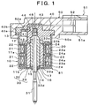
- Figure 1 is a sectional view showing the embodiment to which an enclosed stepping motor in accordance with the present invention is applied
- Figure 2 is a side view showing an appearance of the stepping motor shown in Figure 1 , viewed from the connector direction.
- the stepping motor shown in this embodiment is used as a driving source for such as a mixture flow rate regulating valve (member to which the motor is installed) of a gasoline engine, and is required to have high airtightness in an installed state.
- the stepping motor is a device for converting an electric pulse signal to a step operation for mechanical connection and disconnection.
- the stepping motor shown herein is of a PM type, and is configured so that a rotatingmagnetic field is produced by changing over a current flowing in a stator coil 21, and a rotor magnet 32 having many magnetized poles is synchronously rotated in the peripheral direction.
- This stepping motor is configured so as to include a motor casing 10, a stator 20, a rotor 30, a cover member 40, and a connector body 50.
- the motor casing 10 has a peripheral wall portion 11a formed in a cylindrical shape and an end wall portion 11b for closing an opening at one end of the peripheral wall portion 11a, and is formed integrally in a cup shape by a magnetic metal (for example, iron).
- the stator 20 is provided at the periphery of the rotor 30 in the motor casing 10 to rotationally drive the rotor 30.
- the stator 20 includes coils 21, bobbins 22, and yokes (referred also to as stator cores) 23 and 24.
- the rotor 30 is arranged on the inside of the stator 20 in the motor casing 10 to rotationally drive a motor shaft (output shaft) 31 projecting from the interior of the motor casing 10 through a shaft hole 14 formed in the end wall portion 11b.
- the rotor 30 is configured so as to include a cylindrical rotor body (support shaft portion) 33 fixed coaxially on the outer peripheral surface of the motor shaft 31 and a cylindrical rotor magnet 32 fixed coaxially at the outer periphery of the rotor body 33.
- the cover member 40 is provided so as to close the other end opening 12 of the motor casing 10.
- the cover member 40 is integrally formed of a resin so that a radial bearing surface (bearing portion) 42 for supporting a rear end portion of the rotor 30 is provided in the cover member 40.
- the connector body 50 is integrally formed of a resin so as to seal the other end opening 12 of the motor casing 10 from the outside of the cover member 40.
- the connector body 50 makes the other end opening 12 of the motor casing 10 completely airtight by being molded (for example, injection molded) in the final process of assembly.
- the cover member 40 is formed integrally with the stator 20 using the resin integrally forming the stator 20, and is also formed so as to integrally hold connector pins 52 the distal end portions of which are arranged in the connector body 50 when the connector body 50 is formed.
- the proximal end portion of the connector pin 52 serves as a terminal 52a for connecting the end portion of the coil 21 of the stator 20.
- the stator 20 and the cover member 40 are integrally formed using a resin for forming bobbins 22, the bobbins 22 and the cover member 40 are injection molded (insert injection molded) at the same time in a state in which the plurality of yokes 23 and 24 and the plurality of connector pins 52 are inserted in a mold. Then, the coils 21 are wound on the bobbins 22, and the end portion of the coil 21 is wound on the terminal 52a of the connector pin 52 and connected thereto by soldering, welding, or the like method. Thereby, the stator 20 integral with the cover member 40 can be obtained.
- the terminal 52a of the connector pin 52 is located on the outside in the axial direction of the bobbin 22 of the stator 20, and is provided so as to extend to the outer periphery side of the bobbin 22 along the end surface arranged in the end portion in the axial direction of the bobbin 22.
- the connector body 50 and the connector pins 52 form a waterproof connector 51.
- the cover member 40 is provided with a space 40a which enables the arrangement of terminals 52a of the connector pins 52.
- This space 40a is formed in the cover member 40 by installing a sub-cover member 40b to the cover member 40, and is opened to the outside by removing the sub-cover member 40b.
- the sub-cover member 40b is provided detachably on the cover member 40 as one component of the cover member 40 to form the space 40a in a portion corresponding to the terminals 52a.
- the coil 21 can be wound on and connected to the terminal 52a by exposing the terminal 52a, and the terminal 52a etc. are protected by covering the terminal 52a.
- the cover member 40 closes the whole of the other end opening 12 of the motor casing 10 by means of installation of the sub-cover member 40b.
- the motor casing 10 is provided with an outward flange 13 at the peripheral edge of the other end opening 12.
- a bearing bush 15 is fittingly fixed in the shaft hole 14 formed in the axis portion of the end wall portion 11b.
- the outer periphery of the bearing bush 15 has a step portion 16, so that the bearing bush 15 is prevented from coming off from the shaft hole 14 to the front by fitting the step portion 16 in the shaft hole 14 from the inside of the motor casing 10.
- the bearing bush 15 serves as a thrust bearing surface 17 in which the inner end surface in the axial direction is formed by a plane in the direction perpendicular to the axis of the rotor 30.
- the rotor 30 is inserted in the motor casing 10 through the other end opening 12 of the motor casing 10, and the motor shaft 31 arranged on the axis of the rotor 30 is fitted rotatably in the bearing bush 15. Also, the stator 20 is engaged with the peripheral wall portion 11a of the motor casing 10 so as to be in a state of being close to the outer peripheral surface of the rotor 30.
- the stator 20 is configured by providing a pair of bobbins 22, on which the coils 21 are wound, adjacently in the axial direction, and a pair of yokes 23 and 24 are arranged on each of the bobbins 22.
- the yoke 23, 24 has a plurality of pole teeth 23a, 24a extending in the axial direction along the inner peripheral surface of the bobbin 22 from the end surface in the axial direction of the bobbin 22.
- the pole teeth 23a, 24a are arranged alternately in the circumferential direction.
- the stator 20 constructed as described above is configured so that the peripheral wall portion 11a is brought into close contact with the outer peripheral edge of the yoke 23, 24 by partially decreasing the diameter of the peripheral wall portion 11a in a state in which the stator is inserted in the motor casing 10. Thereby, a closed magnetic circuit is formed by a part of the motor casing 10, the yokes 23 and 24, and the rotor magnet 32.
- the rotor body 33 is integrally formed of a resin (material) having a self-lubricating property, and includes a cylindrical portion 33a and a collar portion 33b formed at the outer periphery in the rear end portion in the axial direction of the cylindrical portion 33a.
- the rotor magnet 32 is engaged with and fixed on the outer peripheral surface in front of the collar portion 33b in the cylindrical portion 33a.
- the outer peripheral surface at the rear of the collar portion 33b in the cylindrical portion 33a serves as a first sliding surface (outer peripheral surface) 33c rotatably engaged with the radial bearing surface 42, and the tip end surface of the cylindrical portion 33a serves as a second sliding surface (one end surface) 33d that is in slidable contact with the thrust bearing surface 17 of the bearing bush 15.
- a resin having a self-lubricating property PPS (polyphenylene sulfide) with which a solid lubricant is mixed is used.
- the rotor 30 is integrated, for example, by injection molding (insert injection molding) the rotor body 33 in a state in which the motor shaft 31 and the rotor magnet 32 are inserted in a mold.
- injection molding insert injection molding
- the rotor 30 is made up of the rotor magnet 32 and the rotor body 33 in this embodiment, the rotor 30 may include the motor shaft 31.
- the cover body 40 is provided with a concave portion 41 in the axis portion on the inside.
- the inner peripheral surface on the opening side of the concave portion 41 serves as the radial bearing surface 42.
- a small-diameter guide concave portion 43 which enables the introduction of the rear end portion of the motor shaft 31, is formed coaxially with the radial bearing surface 42.
- a steel ball 44 and a pressing spring (urging means) 45 are housed in the guide concave portion 43.
- the pressing spring 45 brings the second sliding surface 33d of the rotor body 33 into contact with the thrust bearing surface 17 of the bearing bush 15 by pressing the steel ball 44 against the rear end surface of the motor shaft 31.
- the connector body 50 is molded in the final stage of assembly process so as to wrap the flange 13 of the motor casing 10 from the outside of the cover member 40. Thereby, the other end opening 12 of the motor casing 10 is completely sealed, and the motor casing 10 is fixed firmly. In this case, most portions of the motor casing 10 excluding a portion near the other end opening 12 are in a state of being exposed to the outside.
- a surface directed to the end wall portion 11b side in the axial direction of the motor casing 10 serves as a flange surface 50a for attaching the aforementioned mixture flow rate regulating valve.
- This flange surface 50a is formed by a plane perpendicular to the axial direction of the motor casing 10.
- the motor casing 10 is inserted in an opening of the mixture flow rate regulating valve, and is brought into close contact with a plane-shaped attachment surface at the peripheral edge of this opening, by which the airtightness is kept via a seal member such as an O-ring.
- a connecting portion 51a for the connection with another connector is directed toward the direction perpendicular to the axial direction of the motor casing 10.
- the connector body 50 is molded from the outside of the cover member 40 for closing the other end opening 12 of the cup-shaped motor casing 10, by which the other end opening 12 can be sealed surely. Also, since the connector body 50 is provided with the flange surface 50a, the airtightness in the connecting portion with the mixture flow rate regulating valve can be secured sufficiently.
- the temperature of the coil 21 itself can be decreased, so that poor insulation such as melting of an insulating coating can be prevented, and also thermal deformation of parts such as the coils 21, bobbins 22, yokes 23 and 24, motor casing 10, and cover member 40 can be prevented.
- the temperature of the coil 21 decreases, there is no fear that thermal demagnetization occurs on the magnet 32 of the rotor 30 close to the coil 21, so that the properties as a motor, such as torque, can be prevented from being deteriorated. Therefore, the durability can be improved.
- the portion covered by a resin is small, a small diameter and light weight can be achieved, and also the cost can be reduced by a decrease in the use of resin.
- the other end opening 12 of the motor casing 10 can be closed by inserting the integrated stator 20 and cover member 40 in the motor casing 10, so that the other end opening 12 can be sealed surely merely by molding the connector body 50 from the outside of the cover member 40. Therefore, the manufacture is easy, and hence the productivity can be enhanced.
- the stator 20, the cover member 40, and the connector pins 52 are formed integrally, the number of parts can be decreased. Moreover, since the proximal end portion of the connector pin 52 serves as the terminal 52a for connecting the end portion of the coil 21, work for winding the coil 21 on the stator 20 and for connecting the end portion of the coil 21 to the terminal 52a by soldering etc. can be carried out continuously, and also this work can be mechanized. Since the terminal 52a is provided so as to extend on the outer peripheral side of the bobbin 22 along the end surface in the axial direction of the bobbin 22, the end portion of the coil 21 can be connected easily by the terminal 52a. Therefore, the assembling work and assembling process can be simplified, so that the proportion defective can be decreased, and also the cost can be reduced.
- the sub-cover member 40b for enabling the exposure of the terminal 52a is provided in a portion corresponding to the terminal 52a in the cover member 40, the connection of the end portion of the coil 21 to the terminal 52a is easy, and also the other end opening 12 of the motor casing 10 is closed surely to surely prevent the resin from intruding into the motor casing 10 when the connector body 50 is molded.
- the rotor body 33 is formed of a resin (PPS) having a self-lubricating property, and the first sliding surface 33c formed on the rotor body 33 is directly engaged slidably with the radial bearing surface 42 of the cover member 40 forming a motor housing 81 to obtain a radial supporting force. Therefore, the radial bearing (roller bearing shown in the conventional example), which must be installed usually, can be omitted.
- the configuration is such that the second sliding surface 33d of the rotor body 33 is directly in slidably contact with the thrust bearing surface 17 of the bearing bush 15, the thrust bearing, which must be installed usually, can be omitted. Therefore, the number of parts can be decreased, and a small size, light weight, and low cost can be achieved. Also, the productivity can be enhanced by the simplification of construction.
- the rotor body 33 is formed of a resin having a self-lubricating property, the rotor body 33 can be molded easily by injection molding (molding), and also in the process of molding, the motor shaft 31 and the rotor magnet 32 can be fixed surely to the rotor body 33.
- the urging force of the pressing spring 45 is transmitted to the rotor body 33 via the steel ball 44 and the motor shaft 31, and thereby the rotor body 33 is urged against the second sliding surface 33d side, the second sliding surface 33d is always in contact with the thrust bearing surface 17. Therefore, the rotor 30 can be prevented from being displaced in the axial direction. Moreover, since the steel ball 44 is in contact with the axis position of the end surface of the motor shaft 31, rotational resistance produced on the rotor 30 can be kept at a minimum.
- the configuration may be such that the motor shaft 31 is moved linearly by the rotation of the rotor 30.
- the configuration may be such that an external thread portion provided in an inner peripheral portion of the rotor body 33 is engaged with an internal thread portion provided in an outer peripheral portion of the motor shaft 31, by which the motor shaft 31 is moved in the axial direction along with the rotation of the rotor 30.
- the present invention can be applied to other types of motors.
- this embodiment is configured so that the motor shaft 31 and the rotor magnet 32 are fixed to the rotor 30 by injection molding the rotor body 33
- the configuration may be such that the motor shaft 31 is put under pressure on the inner peripheral surface of the rotor body 33, and the rotor body 33 is put under pressure on the inner peripheral surface of the rotor magnet 32, by which the motor shaft 31 and the rotor magnet 32 are fixed to the rotor body 33.
- the rotor body 33 can be fixed easily.
- the configuration may be such that the motor shaft 31, the rotor body 33, and the rotor magnet 32 may be fixed integrally with an adhesive.
- the configuration may be such that a resin magnet is used as the rotor magnet 32, and this resin magnet is molded integrally with the outer peripheral surface of the rotor body 33, by which the rotor magnet 32 is fixed on the outer peripheral surface of the rotor body 33.
- the rotor magnet 32 can be fixed on the outer peripheral surface of the rotor body 33 by post-molding of resin magnet.
- the radial bearing surface 42 for supporting the rear end of the rotor body 33 is formed on the interior of the cover member 40.
- this can be modified such that, as shown in Figure 3 , a small-sized tubular member 71 having a wear-resistant property is provided on the inner portion (at the rotary support portion) of the cover member 40 so that the outer circumferential surface of the rotor body 33 is rotatably supported through the tubular member 71.
- This modification permits restriction of frictional wear at the rotor body 33 and its rotary support member and also can provide improvements in durability and accuracy of parts (especially, accuracy of parts in the radial direction) , with maintaining the pursuit of miniaturization.
- a small disc-shaped member 72 of wear-resistant property can be mounted between the bearing bush 15 and the end of the rotor body 33, so that frictional wear of the second sliding surface 33d (one end surface) of the rotor body 33 and the thrust bearing surface 17 of the bearing bush 15 can be restrained and, therefore, accuracy of parts (particularly, accuracy of the parts in the thrust direction) and durability as well as pursuit of miniaturization (downsizing) can be attained.
- a bearing having been used conventionally and a resin for covering the motor can be omitted, so that the motor can be made small in size. Also, the heat dissipating properties are improved, so that the durability can be increased.
Description
- The present invention relates to a motor provided with a rotor having a rotor magnet arranged at the periphery thereof, the motor being configured so that an importance is attached to the airtightness and heat dissipating properties.
- As the motor of this type, for example, a stepping motor described in Patent Document 1 has been known. This stepping motor is constructed so that a rotor to which a rotor magnet is fixed is provided on the outer peripheral surface of a support shaft portion, and the rotor is rotatably supported on the outer peripheral surface of the support shaft portion by a roller bearing. Also, the whole of the motor is covered with a resin to hold the airtightness.
- However, in the above-described conventional stepping motor, since the support shaft portion of the rotor is supported by the roller bearing, a space region occupied by the roller bearing is large, which presents a problem in making the motor small in size. Also, the covering of the whole of the motor with a resin causes a hindrance to the miniaturization of motor.
- Further, in the above-described conventional stepping motor, since the whole of the motor is covered with a resin having high heat insulating properties, the heat dissipating properties deteriorate, which also presents a problem in that the durability is decreased by a rise in temperature in the motor. Especially in the case of a stepping motor, since the position of an output shaft is also controlled by maintaining the energization a coil, the interior of motor is liable to become hot. Therefore, the heat dissipating properties must be improved.
- [Patent Document] Japanese Patent Publication No.
8-28958 - Further prior-art is
US 5 254 892 . - The present invention has been made in view of the above situation, and accordingly objects thereof are to provide a motor capable of being made small in size by omitting a bearing used conventionally and a resin for covering the motor, and to provide an enclosed motor capable of improving the durability by enhancing the heat dissipating properties.
- To solve the above problems, a motor in accordance with the present invention is defined in claims 1-3.
- According to the motor constructed as described above, since there is provided the connector body integrally formed of a resin so as to seal the other end opening of the motor casing from the outside of the cover member, the interior of motor casing can be sealed easily and surely, for example, merely by injection molding the connector body.
- Also, although a portion near the other end opening of the motor casing is covered by the resin of connector body for sealing the opening, most portions of the peripheral wall portion formed in a cylindrical shape and the end wall portion are not covered by the resin. Specifically, most portions of the metallic motor casing are in an exposed state. Therefore, the heat generated in the interior can be dissipated efficiently to the outside through the motor casing.
- Therefore, the temperature in the motor casing can be decreased, and hence the durability can be improved. Moreover, since the portion of motor casing covered by the resin is small, a small diameter and light weight can be achieved, and also the cost can be reduced by a decrease in the quantity of resin used.
- In the above-described motor, the cover member is formed integrally with the stator using the resin integrally forming the stator, and also formed so as to integrally hold connector pins the distal end portions of which are arranged in the connector body when the connector body is formed. The proximal end portion of the connector pin serves as a terminal for connecting the end portion of a coil of the stator.
- In the case of such a configuration, work for winding the coil on the stator and for connecting the end portion of the coil to the terminal by soldering etc. can be carried out continuously, and also this work can be mechanized. The other end opening of the motor casing can be closed merely by inserting the integrated stator and cover member in the motor casing.
- Therefore, the assembling work and assembling process can be simplified, so that the proportion defective can be decreased, and also the cost can be reduced.
- Also, in the above-described motor, the terminal of the connector pin is located on the outside in the axial direction of the bobbin on which the coil is wound in the stator, and is provided so as to extend to the outer periphery side of the bobbin along the end surface in the axial direction of the bobbin. According to such a configuration, the work efficiency at the time when the end portion of coil is connected to the terminal can be increased.
- Also, in the above-described motor, a sub-cover member, which enables the exposure of the terminal, is provided in a portion corresponding to the terminal in the cover member. In this case, by removing the sub-cover member, the connection of the end portion of coil to the terminal can be accomplished easily, and by installing the sub-cover member, the other end opening of the motor casing can be closed surely.
- Further, in the above-described motor, the connector body is configured so that a surface directed toward the end wall portion side in the axial direction of the motor casing serves as a flange surface for being installed to a member to which the motor is installed by being brought into contact with the member to which the motor is installed. According to such a configuration, the connector body can be fixed stably to the member to which the motor is installed. Also, for example, when the motor casing is inserted in the member to which the motor is installed, the periphery of the inserted portion of the member to which the motor is installed can be kept airtight by the flange surface.
- Also, in the above-describedmotor, the rotor has a support shaft portion formed of a material having a self-lubricating property and a rotor magnet fixed on the outer peripheral surface of the support shaft portion, and the outer peripheral surface of the support shaft portion is supported rotatably. When the rotor having such a construction is used, a resin covering the motor and a bearing can be omitted, so that far greater effects of decreased size etc. can be achieved.
- According to the motor constructed as described above, since the support shaft portion of the rotor is formed of a material having a self-lubricating property, and the outer peripheral surface of the support shaft portion is supported rotatably, a bearing such as a roller bearing, which has conventionally been needed to rotationally support the rotor, can be omitted.
- Therefore, the motor can be made small in size. Moreover, since the omission of bearing can decrease the number of parts, light weight, simplified construction, and low cost can be achieved, and also the productivity can be improved because of simplified construction.
- Further, in the motor described above, a wear-resistant tubular member of a small size may be mounted on a rotary support portion for the rotor so that an outer peripheral surface of the support shaft portion is rotatably supported through the tubular member. This will permit restriction of frictional wear at the support shaft portion and the rotary support portion, and will be directed to improvements in durability as well as accuracy of parts (especially accuracy of parts in a radial direction) with, at the same time, the pursuit of downsizing and miniaturization is being maintained,
- In the above-described motor, it is preferable that the end surface in the axial direction of the support shaft portion be supported slidably. According to such a configuration, a bearing in the thrust direction can also be omitted.
- Also, in the above-described motor, it is preferable that as the material of the support shaft portion, a resin having a self-lubricating property be used. When such a resin is used as the material of the support shaft portion, the support shaft portion can be formed easily by molding, and also in the process of molding, the rotor magnet can be fixed surely to the support shaft portion.
- Also, in the above-described motor, the rotor magnet may be fixed on the outer peripheral surface of the support shaft portion, for example, by pressing-in, bonding, or post-molding of a resin magnet, or may be fixed on the outer peripheral surface of the support shaft portion by molding the support shaft portion in a state in which the rotor magnet is arranged at the outer periphery. In both of the cases, the rotor magnet can be fixed to the support shaft portion easily. Further, when the support shaft portion is molded in the state in which the rotor magnet is arranged at the outer periphery, in the process in which the support shaft portion is molded, the rotor magnet can be fixed to the support shaft portion surely.
- Also, in the above-described motor, it is preferable that at a position corresponding to one end surface in the axial direction of the support shaft portion, a thrust bearing surface which is in slidably contact with the one end surface be provided, and at a position corresponding to the other end surface in the axial direction of the support shaft portion, urging means for urging from the other end surface side toward the thrust bearing surface side be provided. According to such a configuration, since one end surface of the support shaft portion can be brought into contact with the thrust bearing surface by the urging force from the urging means, the rotor can be prevented from being displaced in the axial direction.
- Further, in the motor described above, a small-sized, wear-resistant disc-shaped member can be provided between one of the axial end surfaces of the support shaft portion and the thrust bearing surface. This can provide improvements in durability and accuracy of parts (particularly, the parts in the axial direction).
-
-
Figure 1 is a sectional view of a stepping motor, showing one embodiment of the present invention; and -
Figure 2 is a side view showing an appearance of the stepping motor shown inFigure 1 , viewed from the connector direction. -
Figure 3 is sectional view of a stepping motor according to a modification of the structure shown byFigure 1 . -
- 10
- Motor casing
- 11a
- Peripheral wall portion
- 11b
- End wall portion
- 12
- The other end opening
- 14
- Shaft hole
- 15
- Bearing bush
- 17
- Thrust bearing surface
- 20
- Stator
- 21
- Coil
- 30
- Rotor
- 31
- Motor shaft (output shaft)
- 32
- Magnet
- 33
- Rotor body (support shaft portion)
- 33c
- First sliding surface (outer peripheral surface)
- 33d
- Second sliding surface (one end surface)
- 40
- Cover member
- 40b
- Sub-cover member
- 42
- Radial bearing surface
- 44
- Steel ball
- 45
- Pressing spring (urging means)
- 50
- Connector body
- 50a
- Flange surface
- 51
- Waterproof connector
- 52
- Connector pin
- 52a
- Terminal
- One embodiment of the present invention will now be described with reference to the accompanying drawings.
-
Figure 1 is a sectional view showing the embodiment to which an enclosed stepping motor in accordance with the present invention is applied, andFigure 2 is a side view showing an appearance of the stepping motor shown inFigure 1 , viewed from the connector direction. - The stepping motor shown in this embodiment is used as a driving source for such as a mixture flow rate regulating valve (member to which the motor is installed) of a gasoline engine, and is required to have high airtightness in an installed state. Generally, the stepping motor is a device for converting an electric pulse signal to a step operation for mechanical connection and disconnection. The stepping motor shown herein is of a PM type, and is configured so that a rotatingmagnetic field is produced by changing over a current flowing in a
stator coil 21, and arotor magnet 32 having many magnetized poles is synchronously rotated in the peripheral direction. - This stepping motor is configured so as to include a
motor casing 10, astator 20, arotor 30, acover member 40, and aconnector body 50. - The
motor casing 10 has a peripheral wall portion 11a formed in a cylindrical shape and anend wall portion 11b for closing an opening at one end of the peripheral wall portion 11a, and is formed integrally in a cup shape by a magnetic metal (for example, iron). Thestator 20 is provided at the periphery of therotor 30 in themotor casing 10 to rotationally drive therotor 30. Thestator 20 includescoils 21,bobbins 22, and yokes (referred also to as stator cores) 23 and 24. Therotor 30 is arranged on the inside of thestator 20 in themotor casing 10 to rotationally drive a motor shaft (output shaft) 31 projecting from the interior of themotor casing 10 through ashaft hole 14 formed in theend wall portion 11b. Therotor 30 is configured so as to include a cylindrical rotor body (support shaft portion) 33 fixed coaxially on the outer peripheral surface of themotor shaft 31 and acylindrical rotor magnet 32 fixed coaxially at the outer periphery of therotor body 33. Thecover member 40 is provided so as to close the other end opening 12 of themotor casing 10. Thecover member 40 is integrally formed of a resin so that a radial bearing surface (bearing portion) 42 for supporting a rear end portion of therotor 30 is provided in thecover member 40. Theconnector body 50 is integrally formed of a resin so as to seal the other end opening 12 of themotor casing 10 from the outside of thecover member 40. Theconnector body 50 makes the other end opening 12 of themotor casing 10 completely airtight by being molded (for example, injection molded) in the final process of assembly. - The
cover member 40 is formed integrally with thestator 20 using the resin integrally forming thestator 20, and is also formed so as to integrally holdconnector pins 52 the distal end portions of which are arranged in theconnector body 50 when theconnector body 50 is formed. The proximal end portion of theconnector pin 52 serves as a terminal 52a for connecting the end portion of thecoil 21 of thestator 20. - For example, when the
stator 20 and thecover member 40 are integrally formed using a resin for formingbobbins 22, thebobbins 22 and thecover member 40 are injection molded (insert injection molded) at the same time in a state in which the plurality ofyokes coils 21 are wound on thebobbins 22, and the end portion of thecoil 21 is wound on the terminal 52a of theconnector pin 52 and connected thereto by soldering, welding, or the like method. Thereby, thestator 20 integral with thecover member 40 can be obtained. - The terminal 52a of the
connector pin 52 is located on the outside in the axial direction of thebobbin 22 of thestator 20, and is provided so as to extend to the outer periphery side of thebobbin 22 along the end surface arranged in the end portion in the axial direction of thebobbin 22. - The
connector body 50 and the connector pins 52 form awaterproof connector 51. Also, thecover member 40 is provided with a space 40a which enables the arrangement of terminals 52a of the connector pins 52. This space 40a is formed in thecover member 40 by installing asub-cover member 40b to thecover member 40, and is opened to the outside by removing thesub-cover member 40b. Specifically, thesub-cover member 40b is provided detachably on thecover member 40 as one component of thecover member 40 to form the space 40a in a portion corresponding to the terminals 52a. Thecoil 21 can be wound on and connected to the terminal 52a by exposing the terminal 52a, and the terminal 52a etc. are protected by covering the terminal 52a. Also, thecover member 40 closes the whole of the other end opening 12 of themotor casing 10 by means of installation of thesub-cover member 40b. - Also, the
motor casing 10 is provided with anoutward flange 13 at the peripheral edge of theother end opening 12. In theshaft hole 14 formed in the axis portion of theend wall portion 11b, a bearingbush 15 is fittingly fixed. The outer periphery of the bearingbush 15 has astep portion 16, so that the bearingbush 15 is prevented from coming off from theshaft hole 14 to the front by fitting thestep portion 16 in theshaft hole 14 from the inside of themotor casing 10. Also, the bearingbush 15 serves as athrust bearing surface 17 in which the inner end surface in the axial direction is formed by a plane in the direction perpendicular to the axis of therotor 30. - The
rotor 30 is inserted in themotor casing 10 through the other end opening 12 of themotor casing 10, and themotor shaft 31 arranged on the axis of therotor 30 is fitted rotatably in the bearingbush 15. Also, thestator 20 is engaged with the peripheral wall portion 11a of themotor casing 10 so as to be in a state of being close to the outer peripheral surface of therotor 30. - Also, the
stator 20 is configured by providing a pair ofbobbins 22, on which thecoils 21 are wound, adjacently in the axial direction, and a pair ofyokes bobbins 22. Theyoke bobbin 22 from the end surface in the axial direction of thebobbin 22. The pole teeth 23a, 24a are arranged alternately in the circumferential direction. - The
stator 20 constructed as described above is configured so that the peripheral wall portion 11a is brought into close contact with the outer peripheral edge of theyoke motor casing 10. Thereby, a closed magnetic circuit is formed by a part of themotor casing 10, theyokes rotor magnet 32. - On the other hand, the
rotor body 33 is integrally formed of a resin (material) having a self-lubricating property, and includes a cylindrical portion 33a and acollar portion 33b formed at the outer periphery in the rear end portion in the axial direction of the cylindrical portion 33a. Therotor magnet 32 is engaged with and fixed on the outer peripheral surface in front of thecollar portion 33b in the cylindrical portion 33a. Also, the outer peripheral surface at the rear of thecollar portion 33b in the cylindrical portion 33a serves as a first sliding surface (outer peripheral surface) 33c rotatably engaged with theradial bearing surface 42, and the tip end surface of the cylindrical portion 33a serves as a second sliding surface (one end surface) 33d that is in slidable contact with thethrust bearing surface 17 of the bearingbush 15. As a resin having a self-lubricating property, PPS (polyphenylene sulfide) with which a solid lubricant is mixed is used. - The
rotor 30 is integrated, for example, by injection molding (insert injection molding) therotor body 33 in a state in which themotor shaft 31 and therotor magnet 32 are inserted in a mold. Although therotor 30 is made up of therotor magnet 32 and therotor body 33 in this embodiment, therotor 30 may include themotor shaft 31. - The
cover body 40 is provided with aconcave portion 41 in the axis portion on the inside. The inner peripheral surface on the opening side of theconcave portion 41 serves as theradial bearing surface 42. Specifically, after therotor 30 is assembled to themotor casing 10, by engaging thecover member 40 to the other end opening 12 of themotor casing 10, the first sliding surface 33c of therotor body 33 engages rotatably with theradial bearing surface 42 of thecover member 40. Thereby, the front end portion and rear end portion of therotor 30 are rotatably supported by the bearingbush 15 and theradial bearing surface 42, respectively. - Also, in the farthest portion of the
concave portion 41, a small-diameter guideconcave portion 43, which enables the introduction of the rear end portion of themotor shaft 31, is formed coaxially with theradial bearing surface 42. In the guideconcave portion 43, asteel ball 44 and a pressing spring (urging means) 45 are housed. Thepressing spring 45 brings the second sliding surface 33d of therotor body 33 into contact with thethrust bearing surface 17 of the bearingbush 15 by pressing thesteel ball 44 against the rear end surface of themotor shaft 31. - The
connector body 50 is molded in the final stage of assembly process so as to wrap theflange 13 of themotor casing 10 from the outside of thecover member 40. Thereby, the other end opening 12 of themotor casing 10 is completely sealed, and themotor casing 10 is fixed firmly. In this case, most portions of themotor casing 10 excluding a portion near the other end opening 12 are in a state of being exposed to the outside. - Also, for the
connector body 50, a surface directed to theend wall portion 11b side in the axial direction of themotor casing 10 serves as a flange surface 50a for attaching the aforementioned mixture flow rate regulating valve. This flange surface 50a is formed by a plane perpendicular to the axial direction of themotor casing 10. For example, themotor casing 10 is inserted in an opening of the mixture flow rate regulating valve, and is brought into close contact with a plane-shaped attachment surface at the peripheral edge of this opening, by which the airtightness is kept via a seal member such as an O-ring. Also, for theconnector body 50 and thewaterproof connector 51 provided with the connector pins 52, a connecting portion 51a for the connection with another connector is directed toward the direction perpendicular to the axial direction of themotor casing 10. - Next, the operation and effects of the stepping motor constructed as described above are explained.
- In this stepping motor, the
connector body 50 is molded from the outside of thecover member 40 for closing the other end opening 12 of the cup-shapedmotor casing 10, by which the other end opening 12 can be sealed surely. Also, since theconnector body 50 is provided with the flange surface 50a, the airtightness in the connecting portion with the mixture flow rate regulating valve can be secured sufficiently. - Also, in this stepping motor, since an open loop is used, a current always flows in the
coil 21, so that even if the amount of generation of Joule heat increases, the heat can be efficiently dissipated to the outside through themetallic motor casing 10 in the state in which most portions thereof is exposed. In this case, the heat generated in thecoil 21 is transmitted to themotor casing 10 via thebobbins 22 and theyokes coil 21 to themotor casing 10 by radiation. - Therefore, the temperature of the
coil 21 itself can be decreased, so that poor insulation such as melting of an insulating coating can be prevented, and also thermal deformation of parts such as thecoils 21,bobbins 22, yokes 23 and 24,motor casing 10, and covermember 40 can be prevented. Moreover, since the temperature of thecoil 21 decreases, there is no fear that thermal demagnetization occurs on themagnet 32 of therotor 30 close to thecoil 21, so that the properties as a motor, such as torque, can be prevented from being deteriorated. Therefore, the durability can be improved. - Also, since the portion covered by a resin is small, a small diameter and light weight can be achieved, and also the cost can be reduced by a decrease in the use of resin.
- On the other hand, the other end opening 12 of the
motor casing 10 can be closed by inserting theintegrated stator 20 andcover member 40 in themotor casing 10, so that the other end opening 12 can be sealed surely merely by molding theconnector body 50 from the outside of thecover member 40. Therefore, the manufacture is easy, and hence the productivity can be enhanced. - Also, since the
stator 20, thecover member 40, and the connector pins 52 are formed integrally, the number of parts can be decreased. Moreover, since the proximal end portion of theconnector pin 52 serves as the terminal 52a for connecting the end portion of thecoil 21, work for winding thecoil 21 on thestator 20 and for connecting the end portion of thecoil 21 to the terminal 52a by soldering etc. can be carried out continuously, and also this work can be mechanized. Since the terminal 52a is provided so as to extend on the outer peripheral side of thebobbin 22 along the end surface in the axial direction of thebobbin 22, the end portion of thecoil 21 can be connected easily by the terminal 52a. Therefore, the assembling work and assembling process can be simplified, so that the proportion defective can be decreased, and also the cost can be reduced. - Further, since the
sub-cover member 40b for enabling the exposure of the terminal 52a is provided in a portion corresponding to the terminal 52a in thecover member 40, the connection of the end portion of thecoil 21 to the terminal 52a is easy, and also the other end opening 12 of themotor casing 10 is closed surely to surely prevent the resin from intruding into themotor casing 10 when theconnector body 50 is molded. - Also, the
rotor body 33 is formed of a resin (PPS) having a self-lubricating property, and the first sliding surface 33c formed on therotor body 33 is directly engaged slidably with theradial bearing surface 42 of thecover member 40 forming amotor housing 81 to obtain a radial supporting force. Therefore, the radial bearing (roller bearing shown in the conventional example), which must be installed usually, can be omitted. Similarly, since the configuration is such that the second sliding surface 33d of therotor body 33 is directly in slidably contact with thethrust bearing surface 17 of the bearingbush 15, the thrust bearing, which must be installed usually, can be omitted. Therefore, the number of parts can be decreased, and a small size, light weight, and low cost can be achieved. Also, the productivity can be enhanced by the simplification of construction. - Further, since the
rotor body 33 is formed of a resin having a self-lubricating property, therotor body 33 can be molded easily by injection molding (molding), and also in the process of molding, themotor shaft 31 and therotor magnet 32 can be fixed surely to therotor body 33. - Also, since the urging force of the
pressing spring 45 is transmitted to therotor body 33 via thesteel ball 44 and themotor shaft 31, and thereby therotor body 33 is urged against the second sliding surface 33d side, the second sliding surface 33d is always in contact with thethrust bearing surface 17. Therefore, therotor 30 can be prevented from being displaced in the axial direction. Moreover, since thesteel ball 44 is in contact with the axis position of the end surface of themotor shaft 31, rotational resistance produced on therotor 30 can be kept at a minimum. - Although the above-described embodiment is configured so that the
motor shaft 31 is rotated integrally with therotor 30, the configuration may be such that themotor shaft 31 is moved linearly by the rotation of therotor 30. Specifically, the configuration may be such that an external thread portion provided in an inner peripheral portion of therotor body 33 is engaged with an internal thread portion provided in an outer peripheral portion of themotor shaft 31, by which themotor shaft 31 is moved in the axial direction along with the rotation of therotor 30. - Also, although an example in which the present invention is applied to a stepping motor has been shown in this embodiment, the present invention can be applied to other types of motors.
- Further, although this embodiment is configured so that the
motor shaft 31 and therotor magnet 32 are fixed to therotor 30 by injection molding therotor body 33, the configuration may be such that themotor shaft 31 is put under pressure on the inner peripheral surface of therotor body 33, and therotor body 33 is put under pressure on the inner peripheral surface of therotor magnet 32, by which themotor shaft 31 and therotor magnet 32 are fixed to therotor body 33. In this case as well, therotor body 33 can be fixed easily. - Also, the configuration may be such that the
motor shaft 31, therotor body 33, and therotor magnet 32 may be fixed integrally with an adhesive. Further, the configuration may be such that a resin magnet is used as therotor magnet 32, and this resin magnet is molded integrally with the outer peripheral surface of therotor body 33, by which therotor magnet 32 is fixed on the outer peripheral surface of therotor body 33. Specifically, therotor magnet 32 can be fixed on the outer peripheral surface of therotor body 33 by post-molding of resin magnet. - In the embodiment of the invention described above, the
radial bearing surface 42 for supporting the rear end of therotor body 33 is formed on the interior of thecover member 40. However, this can be modified such that, as shown inFigure 3 , a small-sized tubular member 71 having a wear-resistant property is provided on the inner portion (at the rotary support portion) of thecover member 40 so that the outer circumferential surface of therotor body 33 is rotatably supported through thetubular member 71. This modification permits restriction of frictional wear at therotor body 33 and its rotary support member and also can provide improvements in durability and accuracy of parts (especially, accuracy of parts in the radial direction) , with maintaining the pursuit of miniaturization. Similarly, a small disc-shapedmember 72 of wear-resistant property can be mounted between the bearingbush 15 and the end of therotor body 33, so that frictional wear of the second sliding surface 33d (one end surface) of therotor body 33 and thethrust bearing surface 17 of the bearingbush 15 can be restrained and, therefore, accuracy of parts (particularly, accuracy of the parts in the thrust direction) and durability as well as pursuit of miniaturization (downsizing) can be attained. - A bearing having been used conventionally and a resin for covering the motor can be omitted, so that the motor can be made small in size. Also, the heat dissipating properties are improved, so that the durability can be increased.
Claims (3)
- An enclosed motor, comprising:a metallic motor casing (10) having a peripheral wall portion (11a) formed in a cylindrical shape and an end wall portion (11b) for closing one end opening of said peripheral wall portion;a rotor (30) provided in said metallic motor casing (10) to drive an output shaft (31) projecting from said metallic motor casing through a shaft hole (14) in said end wall portion (11b);a stator (20) provided at the periphery of said rotor (30) in said metallic motor casing (10) to rotationally drive said rotor (30) ;a cover member (40) provided to close the other end opening of said metallic motor casing (10); characterized bya connector body (50) integrally formed of a resin so as to close the other end opening of said metallic motor casing (10) from the outside of said cover member (40), whereinsaid cover member (40) is formed integrally with said stator (20) using a resin for integrally forming said stator, and is formed so as to integrally hold a connector pin (52), a portion on a distal end side of which is arranged in said connector body (50) when said connector body is molded,a proximal end portion of said connector pin (52) serving as a terminal (52a) for connecting an end portion of a coil (21) in said stator (20),said terminal (52a) is located outside a bobbin (22) in the axial direction of the bobbin (22) on which said coil (21) in said stator (20) is wound, and the terminal extends parallel to an end surface of the bobbin, the end surface being an end of the bobbin in the axial direction, and the portion of the distal end side of the connector pin (52) which is arranged in said connector body (50) is provided so as to extend to an outer periphery side of said bobbin (22) along and parallel to the end surface of said bobbin.
- The enclosed motor according to claim 1, wherein said connector body (50) is configured so that a surface directed toward the end wall portion side in the axial direction of said metallic motor casing (10) serves as a flange surface (50a) for being installed to a member to which the motor is installed by being brought into contact with the member to which the motor is installed.
- The enclosed motor according to claim 1, wherein said rotor (30) has a support shaft portion (33) formed of a material having a self-lubricating property and a rotor magnet (32) fixed on the outer peripheral surface of the support shaft portion, and the outer peripheral surface of the support shaft portion is supported rotatably.
Applications Claiming Priority (2)
| Application Number | Priority Date | Filing Date | Title |
|---|---|---|---|
| JP2004056429A JP2005253138A (en) | 2004-03-01 | 2004-03-01 | Motor |
| PCT/JP2005/001072 WO2005083870A1 (en) | 2004-03-01 | 2005-01-27 | Motor |
Publications (3)
| Publication Number | Publication Date |
|---|---|
| EP1729400A1 EP1729400A1 (en) | 2006-12-06 |
| EP1729400A4 EP1729400A4 (en) | 2012-10-24 |
| EP1729400B1 true EP1729400B1 (en) | 2016-09-21 |
Family
ID=34908918
Family Applications (1)
| Application Number | Title | Priority Date | Filing Date |
|---|---|---|---|
| EP05704178.2A Active EP1729400B1 (en) | 2004-03-01 | 2005-01-27 | Motor |
Country Status (7)
| Country | Link |
|---|---|
| US (1) | US7816819B2 (en) |
| EP (1) | EP1729400B1 (en) |
| JP (1) | JP2005253138A (en) |
| CN (1) | CN100594653C (en) |
| BR (1) | BRPI0507101A8 (en) |
| TW (1) | TWI362163B (en) |
| WO (1) | WO2005083870A1 (en) |
Families Citing this family (19)
| Publication number | Priority date | Publication date | Assignee | Title |
|---|---|---|---|---|
| JPWO2008069016A1 (en) * | 2006-12-04 | 2010-03-18 | 三菱電機株式会社 | DC motor |
| US8616522B2 (en) * | 2007-07-10 | 2013-12-31 | Continental Tire Canada, Inc. | Idle air control valve |
| DE112008003499B4 (en) | 2007-12-27 | 2017-11-16 | Mitsubishi Electric Corp. | Bearing device for a rotary motor |
| KR101143264B1 (en) * | 2009-07-03 | 2012-05-14 | 주식회사 모아텍 | Step motor |
| JP5653746B2 (en) * | 2010-12-24 | 2015-01-14 | ミネベア株式会社 | Stepping motor for meter |
| DE102011080265A1 (en) * | 2011-08-02 | 2013-02-07 | Schaeffler Technologies AG & Co. KG | Housing unit with molded plastic flange for an electric motor and electric motor with such a housing unit |
| US8636612B2 (en) * | 2012-02-08 | 2014-01-28 | Remy Technologies, L.L.C. | Center adapter assembly |
| JP6427333B2 (en) * | 2014-04-16 | 2018-11-21 | 株式会社不二工機 | Forming method of electromagnetic drive coil device |
| JP6260577B2 (en) * | 2015-04-16 | 2018-01-17 | コベルコ建機株式会社 | Generator motor |
| KR102596664B1 (en) * | 2016-07-18 | 2023-11-02 | 엘지이노텍 주식회사 | Motor |
| DE102017102629B4 (en) * | 2017-02-09 | 2022-12-29 | Johnson Electric Germany GmbH & Co. KG | Stator for a linear stepping motor and method for its manufacture |
| JP2018147650A (en) | 2017-03-03 | 2018-09-20 | 日本電産サンキョー株式会社 | Connection structure of electric parts and connection method of electric parts |
| CN108631476A (en) * | 2017-03-20 | 2018-10-09 | 大陆汽车电子(芜湖)有限公司 | Stepper motor |
| CN107017724B (en) * | 2017-05-25 | 2023-07-21 | 珠海格力节能环保制冷技术研究中心有限公司 | Motor with a motor housing |
| DE102017209519B4 (en) * | 2017-06-07 | 2024-03-28 | Vitesco Technologies Germany Gmbh | Electronic component and method for its production |
| JP7039363B2 (en) * | 2018-03-30 | 2022-03-22 | 日本電産サンキョー株式会社 | motor |
| JP7072427B2 (en) * | 2018-03-30 | 2022-05-20 | 日本電産サンキョー株式会社 | motor |
| JP7072428B2 (en) * | 2018-03-30 | 2022-05-20 | 日本電産サンキョー株式会社 | Motor and motor manufacturing method |
| JP2019180134A (en) * | 2018-03-30 | 2019-10-17 | 日本電産サンキョー株式会社 | motor |
Family Cites Families (22)
| Publication number | Priority date | Publication date | Assignee | Title |
|---|---|---|---|---|
| US4333026A (en) * | 1980-12-08 | 1982-06-01 | General Motors Corporation | Stepping motor |
| JPS59135087A (en) | 1983-01-20 | 1984-08-03 | 三菱重工業株式会社 | Model ship |
| JPS59138387A (en) | 1983-01-28 | 1984-08-08 | Nippon Telegr & Teleph Corp <Ntt> | Solar battery |
| JPS59135087U (en) * | 1983-02-26 | 1984-09-10 | シナノケンシ株式会社 | Permanent magnet step motor |
| JPS59138387U (en) * | 1983-03-03 | 1984-09-14 | 株式会社本田ロツク | motor |
| JPH0428214Y2 (en) * | 1985-12-28 | 1992-07-08 | ||
| GB2225672B (en) * | 1988-09-22 | 1992-10-07 | Johnson Electric Ind Mfg | Splashproof cover for an electric motor |
| JPH0461454A (en) | 1990-06-29 | 1992-02-27 | Nippon Telegr & Teleph Corp <Ntt> | Duplex relay amplifier |
| JP2534683Y2 (en) * | 1990-07-16 | 1997-05-07 | 愛三工業株式会社 | Step motor terminal fixing structure |
| JP2535755Y2 (en) * | 1990-09-29 | 1997-05-14 | 日本電産株式会社 | motor |
| US5254892A (en) * | 1991-12-30 | 1993-10-19 | North American Philips Corporation | Stepper motor with integrated assembly |
| JP3327406B2 (en) * | 1992-01-22 | 2002-09-24 | セイコーエプソン株式会社 | PM type stepping motor |
| US5334897A (en) * | 1993-05-24 | 1994-08-02 | North American Philips Corporation | Electric motor with encased housing |
| JP2592408B2 (en) | 1994-07-19 | 1997-03-19 | 杉村 允生 | Midnight power water heater |
| JPH09247919A (en) * | 1996-03-08 | 1997-09-19 | Minebea Co Ltd | Structure of motor |
| JP3640815B2 (en) * | 1998-11-05 | 2005-04-20 | 株式会社東芝 | Fan device and refrigerator |
| US6492751B1 (en) * | 1999-01-29 | 2002-12-10 | Siemens Vdo Automotive Corporation | Magnetic device with spaced apart pole plates, flux return strip and electrical connector having integral mounting |
| US6455973B1 (en) * | 1999-01-29 | 2002-09-24 | Siemens Vdo Automotive Corp. | Magnetic device with flux return strip |
| US6669166B2 (en) * | 2000-07-28 | 2003-12-30 | Nippon Soken, Inc. | Electromagnetic valve |
| JP3911671B2 (en) * | 2002-05-30 | 2007-05-09 | ミネベア株式会社 | motor |
| JP4578049B2 (en) * | 2002-07-11 | 2010-11-10 | 三菱電機株式会社 | Brushless DC motor |
| KR100474425B1 (en) * | 2003-04-30 | 2005-03-10 | 삼성전자주식회사 | Hinge apparatus for cover of office machine |
-
2004
- 2004-03-01 JP JP2004056429A patent/JP2005253138A/en active Pending
-
2005
- 2005-01-27 CN CN200580006640A patent/CN100594653C/en active Active
- 2005-01-27 US US10/583,761 patent/US7816819B2/en active Active
- 2005-01-27 WO PCT/JP2005/001072 patent/WO2005083870A1/en not_active Application Discontinuation
- 2005-01-27 EP EP05704178.2A patent/EP1729400B1/en active Active
- 2005-01-27 BR BRPI0507101A patent/BRPI0507101A8/en not_active Application Discontinuation
- 2005-02-15 TW TW094104345A patent/TWI362163B/en not_active IP Right Cessation
Also Published As
| Publication number | Publication date |
|---|---|
| EP1729400A1 (en) | 2006-12-06 |
| US20090140584A1 (en) | 2009-06-04 |
| CN1926747A (en) | 2007-03-07 |
| WO2005083870A1 (en) | 2005-09-09 |
| TW200531410A (en) | 2005-09-16 |
| EP1729400A4 (en) | 2012-10-24 |
| CN100594653C (en) | 2010-03-17 |
| BRPI0507101A8 (en) | 2018-04-24 |
| US7816819B2 (en) | 2010-10-19 |
| BRPI0507101A (en) | 2007-06-19 |
| JP2005253138A (en) | 2005-09-15 |
| TWI362163B (en) | 2012-04-11 |
Similar Documents
| Publication | Publication Date | Title |
|---|---|---|
| EP1729400B1 (en) | Motor | |
| US8138645B2 (en) | Electric motor, rotary actuator and rotary apparatus | |
| JP4457038B2 (en) | Motor driven throttle control device for internal combustion engine | |
| JP4695929B2 (en) | Non-contact rotation angle detection device, manufacturing method thereof, and throttle valve control device using the same | |
| JP4531359B2 (en) | motor | |
| US7378768B2 (en) | Stepping motor and method of manufacturing the same | |
| JP2003348785A (en) | Motor | |
| US7348698B2 (en) | Actuator for operating a transmission control valve of an automatic transmission apparatus | |
| US20220263395A1 (en) | Electric Actuating Unit | |
| JP4565913B2 (en) | Actuator | |
| JP4470524B2 (en) | Sealed motor | |
| JP5046094B2 (en) | Linear actuator | |
| WO2018003085A1 (en) | Vehicle-mounted actuator | |
| JP7072427B2 (en) | motor | |
| JP6043655B2 (en) | Engine starter | |
| JP4699499B2 (en) | motor | |
| JP2005253137A (en) | Motor | |
| JP7039363B2 (en) | motor | |
| WO2021200475A1 (en) | Permanent magnet motor | |
| JP4932803B2 (en) | motor | |
| CN117955283A (en) | Motor with a motor housing having a motor housing with a motor housing | |
| JP2019180135A (en) | motor | |
| JP2006296086A (en) | Stepping motor with lead screw | |
| JPWO2008069016A1 (en) | DC motor | |
| JPWO2012127516A1 (en) | Motor and actuator, and motor manufacturing method |
Legal Events
| Date | Code | Title | Description |
|---|---|---|---|
| PUAI | Public reference made under article 153(3) epc to a published international application that has entered the european phase |
Free format text: ORIGINAL CODE: 0009012 |
|
| AK | Designated contracting states |
Kind code of ref document: A1 Designated state(s): AT BE BG CH CY CZ DE DK EE ES FI FR GB GR HU IE IS IT LI LT LU MC NL PL PT RO SE SI SK TR |
|
| 17P | Request for examination filed |
Effective date: 20060829 |
|
| DAX | Request for extension of the european patent (deleted) | ||
| A4 | Supplementary search report drawn up and despatched |
Effective date: 20120920 |
|
| RIC1 | Information provided on ipc code assigned before grant |
Ipc: H02K 37/14 20060101ALI20120914BHEP Ipc: H02K 5/22 20060101ALI20120914BHEP Ipc: H02K 5/167 20060101AFI20120914BHEP |
|
| 17Q | First examination report despatched |
Effective date: 20130123 |
|
| GRAP | Despatch of communication of intention to grant a patent |
Free format text: ORIGINAL CODE: EPIDOSNIGR1 |
|
| INTG | Intention to grant announced |
Effective date: 20160411 |
|
| GRAS | Grant fee paid |
Free format text: ORIGINAL CODE: EPIDOSNIGR3 |
|
| GRAA | (expected) grant |
Free format text: ORIGINAL CODE: 0009210 |
|
| AK | Designated contracting states |
Kind code of ref document: B1 Designated state(s): AT BE BG CH CY CZ DE DK EE ES FI FR GB GR HU IE IS IT LI LT LU MC NL PL PT RO SE SI SK TR |
|
| REG | Reference to a national code |
Ref country code: GB Ref legal event code: FG4D |
|
| REG | Reference to a national code |
Ref country code: CH Ref legal event code: EP |
|
| REG | Reference to a national code |
Ref country code: AT Ref legal event code: REF Ref document number: 831747 Country of ref document: AT Kind code of ref document: T Effective date: 20161015 |
|
| REG | Reference to a national code |
Ref country code: IE Ref legal event code: FG4D |
|
| REG | Reference to a national code |
Ref country code: DE Ref legal event code: R096 Ref document number: 602005050268 Country of ref document: DE |
|
| REG | Reference to a national code |
Ref country code: LT Ref legal event code: MG4D Ref country code: NL Ref legal event code: MP Effective date: 20160921 |
|
| REG | Reference to a national code |
Ref country code: FR Ref legal event code: PLFP Year of fee payment: 13 |
|
| PG25 | Lapsed in a contracting state [announced via postgrant information from national office to epo] |
Ref country code: LT Free format text: LAPSE BECAUSE OF FAILURE TO SUBMIT A TRANSLATION OF THE DESCRIPTION OR TO PAY THE FEE WITHIN THE PRESCRIBED TIME-LIMIT Effective date: 20160921 Ref country code: FI Free format text: LAPSE BECAUSE OF FAILURE TO SUBMIT A TRANSLATION OF THE DESCRIPTION OR TO PAY THE FEE WITHIN THE PRESCRIBED TIME-LIMIT Effective date: 20160921 |
|
| REG | Reference to a national code |
Ref country code: AT Ref legal event code: MK05 Ref document number: 831747 Country of ref document: AT Kind code of ref document: T Effective date: 20160921 |
|
| PG25 | Lapsed in a contracting state [announced via postgrant information from national office to epo] |
Ref country code: GR Free format text: LAPSE BECAUSE OF FAILURE TO SUBMIT A TRANSLATION OF THE DESCRIPTION OR TO PAY THE FEE WITHIN THE PRESCRIBED TIME-LIMIT Effective date: 20161222 Ref country code: NL Free format text: LAPSE BECAUSE OF FAILURE TO SUBMIT A TRANSLATION OF THE DESCRIPTION OR TO PAY THE FEE WITHIN THE PRESCRIBED TIME-LIMIT Effective date: 20160921 Ref country code: SE Free format text: LAPSE BECAUSE OF FAILURE TO SUBMIT A TRANSLATION OF THE DESCRIPTION OR TO PAY THE FEE WITHIN THE PRESCRIBED TIME-LIMIT Effective date: 20160921 |
|
| PG25 | Lapsed in a contracting state [announced via postgrant information from national office to epo] |
Ref country code: RO Free format text: LAPSE BECAUSE OF FAILURE TO SUBMIT A TRANSLATION OF THE DESCRIPTION OR TO PAY THE FEE WITHIN THE PRESCRIBED TIME-LIMIT Effective date: 20160921 Ref country code: EE Free format text: LAPSE BECAUSE OF FAILURE TO SUBMIT A TRANSLATION OF THE DESCRIPTION OR TO PAY THE FEE WITHIN THE PRESCRIBED TIME-LIMIT Effective date: 20160921 |
|
| PG25 | Lapsed in a contracting state [announced via postgrant information from national office to epo] |
Ref country code: BE Free format text: LAPSE BECAUSE OF FAILURE TO SUBMIT A TRANSLATION OF THE DESCRIPTION OR TO PAY THE FEE WITHIN THE PRESCRIBED TIME-LIMIT Effective date: 20160921 Ref country code: PT Free format text: LAPSE BECAUSE OF FAILURE TO SUBMIT A TRANSLATION OF THE DESCRIPTION OR TO PAY THE FEE WITHIN THE PRESCRIBED TIME-LIMIT Effective date: 20170123 Ref country code: IS Free format text: LAPSE BECAUSE OF FAILURE TO SUBMIT A TRANSLATION OF THE DESCRIPTION OR TO PAY THE FEE WITHIN THE PRESCRIBED TIME-LIMIT Effective date: 20170121 Ref country code: PL Free format text: LAPSE BECAUSE OF FAILURE TO SUBMIT A TRANSLATION OF THE DESCRIPTION OR TO PAY THE FEE WITHIN THE PRESCRIBED TIME-LIMIT Effective date: 20160921 Ref country code: BG Free format text: LAPSE BECAUSE OF FAILURE TO SUBMIT A TRANSLATION OF THE DESCRIPTION OR TO PAY THE FEE WITHIN THE PRESCRIBED TIME-LIMIT Effective date: 20161221 Ref country code: SK Free format text: LAPSE BECAUSE OF FAILURE TO SUBMIT A TRANSLATION OF THE DESCRIPTION OR TO PAY THE FEE WITHIN THE PRESCRIBED TIME-LIMIT Effective date: 20160921 Ref country code: ES Free format text: LAPSE BECAUSE OF FAILURE TO SUBMIT A TRANSLATION OF THE DESCRIPTION OR TO PAY THE FEE WITHIN THE PRESCRIBED TIME-LIMIT Effective date: 20160921 Ref country code: AT Free format text: LAPSE BECAUSE OF FAILURE TO SUBMIT A TRANSLATION OF THE DESCRIPTION OR TO PAY THE FEE WITHIN THE PRESCRIBED TIME-LIMIT Effective date: 20160921 |
|
| REG | Reference to a national code |
Ref country code: DE Ref legal event code: R097 Ref document number: 602005050268 Country of ref document: DE |
|
| PLBE | No opposition filed within time limit |
Free format text: ORIGINAL CODE: 0009261 |
|
| STAA | Information on the status of an ep patent application or granted ep patent |
Free format text: STATUS: NO OPPOSITION FILED WITHIN TIME LIMIT |
|
| PG25 | Lapsed in a contracting state [announced via postgrant information from national office to epo] |
Ref country code: DK Free format text: LAPSE BECAUSE OF FAILURE TO SUBMIT A TRANSLATION OF THE DESCRIPTION OR TO PAY THE FEE WITHIN THE PRESCRIBED TIME-LIMIT Effective date: 20160921 |
|
| 26N | No opposition filed |
Effective date: 20170622 |
|
| REG | Reference to a national code |
Ref country code: CH Ref legal event code: PL |
|
| GBPC | Gb: european patent ceased through non-payment of renewal fee |
Effective date: 20170127 |
|
| PG25 | Lapsed in a contracting state [announced via postgrant information from national office to epo] |
Ref country code: MC Free format text: LAPSE BECAUSE OF FAILURE TO SUBMIT A TRANSLATION OF THE DESCRIPTION OR TO PAY THE FEE WITHIN THE PRESCRIBED TIME-LIMIT Effective date: 20160921 |
|
| PG25 | Lapsed in a contracting state [announced via postgrant information from national office to epo] |
Ref country code: CH Free format text: LAPSE BECAUSE OF NON-PAYMENT OF DUE FEES Effective date: 20170131 Ref country code: LI Free format text: LAPSE BECAUSE OF NON-PAYMENT OF DUE FEES Effective date: 20170131 |
|
| REG | Reference to a national code |
Ref country code: IE Ref legal event code: MM4A |
|
| PG25 | Lapsed in a contracting state [announced via postgrant information from national office to epo] |
Ref country code: GB Free format text: LAPSE BECAUSE OF NON-PAYMENT OF DUE FEES Effective date: 20170127 Ref country code: SI Free format text: LAPSE BECAUSE OF FAILURE TO SUBMIT A TRANSLATION OF THE DESCRIPTION OR TO PAY THE FEE WITHIN THE PRESCRIBED TIME-LIMIT Effective date: 20160921 Ref country code: LU Free format text: LAPSE BECAUSE OF NON-PAYMENT OF DUE FEES Effective date: 20170127 |
|
| REG | Reference to a national code |
Ref country code: FR Ref legal event code: PLFP Year of fee payment: 14 |
|
| PG25 | Lapsed in a contracting state [announced via postgrant information from national office to epo] |
Ref country code: IE Free format text: LAPSE BECAUSE OF NON-PAYMENT OF DUE FEES Effective date: 20170127 |
|
| PG25 | Lapsed in a contracting state [announced via postgrant information from national office to epo] |
Ref country code: HU Free format text: LAPSE BECAUSE OF FAILURE TO SUBMIT A TRANSLATION OF THE DESCRIPTION OR TO PAY THE FEE WITHIN THE PRESCRIBED TIME-LIMIT; INVALID AB INITIO Effective date: 20050127 |
|
| PG25 | Lapsed in a contracting state [announced via postgrant information from national office to epo] |
Ref country code: CY Free format text: LAPSE BECAUSE OF NON-PAYMENT OF DUE FEES Effective date: 20160921 |
|
| PGFP | Annual fee paid to national office [announced via postgrant information from national office to epo] |
Ref country code: FR Payment date: 20191216 Year of fee payment: 16 |
|
| PG25 | Lapsed in a contracting state [announced via postgrant information from national office to epo] |
Ref country code: TR Free format text: LAPSE BECAUSE OF FAILURE TO SUBMIT A TRANSLATION OF THE DESCRIPTION OR TO PAY THE FEE WITHIN THE PRESCRIBED TIME-LIMIT Effective date: 20160921 |
|
| PGFP | Annual fee paid to national office [announced via postgrant information from national office to epo] |
Ref country code: IT Payment date: 20200114 Year of fee payment: 16 |
|
| PGFP | Annual fee paid to national office [announced via postgrant information from national office to epo] |
Ref country code: CZ Payment date: 20200122 Year of fee payment: 16 |
|
| PG25 | Lapsed in a contracting state [announced via postgrant information from national office to epo] |
Ref country code: CZ Free format text: LAPSE BECAUSE OF NON-PAYMENT OF DUE FEES Effective date: 20210127 Ref country code: FR Free format text: LAPSE BECAUSE OF NON-PAYMENT OF DUE FEES Effective date: 20210131 |
|
| PG25 | Lapsed in a contracting state [announced via postgrant information from national office to epo] |
Ref country code: IT Free format text: LAPSE BECAUSE OF NON-PAYMENT OF DUE FEES Effective date: 20210127 |
|
| PGFP | Annual fee paid to national office [announced via postgrant information from national office to epo] |
Ref country code: DE Payment date: 20230119 Year of fee payment: 19 |