EP1729036B1 - Hydraulic clutch control system and corresponding method - Google Patents
Hydraulic clutch control system and corresponding method Download PDFInfo
- Publication number
- EP1729036B1 EP1729036B1 EP06009576A EP06009576A EP1729036B1 EP 1729036 B1 EP1729036 B1 EP 1729036B1 EP 06009576 A EP06009576 A EP 06009576A EP 06009576 A EP06009576 A EP 06009576A EP 1729036 B1 EP1729036 B1 EP 1729036B1
- Authority
- EP
- European Patent Office
- Prior art keywords
- hydraulic pressure
- hydraulic
- clutch
- piston
- signal
- Prior art date
- Legal status (The legal status is an assumption and is not a legal conclusion. Google has not performed a legal analysis and makes no representation as to the accuracy of the status listed.)
- Ceased
Links
- 238000000034 method Methods 0.000 title claims description 11
- 238000001514 detection method Methods 0.000 claims description 36
- 230000007274 generation of a signal involved in cell-cell signaling Effects 0.000 claims description 26
- 230000004044 response Effects 0.000 claims description 17
- 230000000977 initiatory effect Effects 0.000 claims description 16
- 230000001939 inductive effect Effects 0.000 claims description 3
- 230000007246 mechanism Effects 0.000 description 32
- 239000010720 hydraulic oil Substances 0.000 description 14
- 230000005540 biological transmission Effects 0.000 description 11
- 230000008859 change Effects 0.000 description 5
- 230000004069 differentiation Effects 0.000 description 5
- 230000007423 decrease Effects 0.000 description 4
- 239000010705 motor oil Substances 0.000 description 4
- 230000001105 regulatory effect Effects 0.000 description 4
- 230000003247 decreasing effect Effects 0.000 description 3
- 239000003921 oil Substances 0.000 description 3
- 238000012546 transfer Methods 0.000 description 3
- 238000006243 chemical reaction Methods 0.000 description 2
- 230000001276 controlling effect Effects 0.000 description 2
- 238000006073 displacement reaction Methods 0.000 description 2
- 230000000694 effects Effects 0.000 description 2
- 230000004048 modification Effects 0.000 description 2
- 238000012986 modification Methods 0.000 description 2
- 230000001133 acceleration Effects 0.000 description 1
- 230000033228 biological regulation Effects 0.000 description 1
- 238000002485 combustion reaction Methods 0.000 description 1
- 238000004891 communication Methods 0.000 description 1
- 238000013461 design Methods 0.000 description 1
- 238000012544 monitoring process Methods 0.000 description 1
- 230000007935 neutral effect Effects 0.000 description 1
- 230000000737 periodic effect Effects 0.000 description 1
- 230000010363 phase shift Effects 0.000 description 1
- 238000005381 potential energy Methods 0.000 description 1
- 230000008569 process Effects 0.000 description 1
- 230000035939 shock Effects 0.000 description 1
Images


Classifications
-
- F—MECHANICAL ENGINEERING; LIGHTING; HEATING; WEAPONS; BLASTING
- F16—ENGINEERING ELEMENTS AND UNITS; GENERAL MEASURES FOR PRODUCING AND MAINTAINING EFFECTIVE FUNCTIONING OF MACHINES OR INSTALLATIONS; THERMAL INSULATION IN GENERAL
- F16H—GEARING
- F16H61/00—Control functions within control units of change-speed- or reversing-gearings for conveying rotary motion ; Control of exclusively fluid gearing, friction gearing, gearings with endless flexible members or other particular types of gearing
- F16H61/18—Preventing unintentional or unsafe shift, e.g. preventing manual shift from highest gear to reverse gear
-
- F—MECHANICAL ENGINEERING; LIGHTING; HEATING; WEAPONS; BLASTING
- F16—ENGINEERING ELEMENTS AND UNITS; GENERAL MEASURES FOR PRODUCING AND MAINTAINING EFFECTIVE FUNCTIONING OF MACHINES OR INSTALLATIONS; THERMAL INSULATION IN GENERAL
- F16H—GEARING
- F16H61/00—Control functions within control units of change-speed- or reversing-gearings for conveying rotary motion ; Control of exclusively fluid gearing, friction gearing, gearings with endless flexible members or other particular types of gearing
- F16H61/04—Smoothing ratio shift
- F16H61/06—Smoothing ratio shift by controlling rate of change of fluid pressure
- F16H61/061—Smoothing ratio shift by controlling rate of change of fluid pressure using electric control means
-
- F—MECHANICAL ENGINEERING; LIGHTING; HEATING; WEAPONS; BLASTING
- F16—ENGINEERING ELEMENTS AND UNITS; GENERAL MEASURES FOR PRODUCING AND MAINTAINING EFFECTIVE FUNCTIONING OF MACHINES OR INSTALLATIONS; THERMAL INSULATION IN GENERAL
- F16D—COUPLINGS FOR TRANSMITTING ROTATION; CLUTCHES; BRAKES
- F16D13/00—Friction clutches
- F16D13/58—Details
- F16D13/75—Features relating to adjustment, e.g. slack adjusters
-
- F—MECHANICAL ENGINEERING; LIGHTING; HEATING; WEAPONS; BLASTING
- F16—ENGINEERING ELEMENTS AND UNITS; GENERAL MEASURES FOR PRODUCING AND MAINTAINING EFFECTIVE FUNCTIONING OF MACHINES OR INSTALLATIONS; THERMAL INSULATION IN GENERAL
- F16H—GEARING
- F16H61/00—Control functions within control units of change-speed- or reversing-gearings for conveying rotary motion ; Control of exclusively fluid gearing, friction gearing, gearings with endless flexible members or other particular types of gearing
- F16H61/04—Smoothing ratio shift
- F16H61/06—Smoothing ratio shift by controlling rate of change of fluid pressure
- F16H61/061—Smoothing ratio shift by controlling rate of change of fluid pressure using electric control means
- F16H2061/064—Smoothing ratio shift by controlling rate of change of fluid pressure using electric control means for calibration of pressure levels for friction members, e.g. by monitoring the speed change of transmission shafts
-
- F—MECHANICAL ENGINEERING; LIGHTING; HEATING; WEAPONS; BLASTING
- F16—ENGINEERING ELEMENTS AND UNITS; GENERAL MEASURES FOR PRODUCING AND MAINTAINING EFFECTIVE FUNCTIONING OF MACHINES OR INSTALLATIONS; THERMAL INSULATION IN GENERAL
- F16H—GEARING
- F16H61/00—Control functions within control units of change-speed- or reversing-gearings for conveying rotary motion ; Control of exclusively fluid gearing, friction gearing, gearings with endless flexible members or other particular types of gearing
- F16H61/26—Generation or transmission of movements for final actuating mechanisms
- F16H61/28—Generation or transmission of movements for final actuating mechanisms with at least one movement of the final actuating mechanism being caused by a non-mechanical force, e.g. power-assisted
- F16H2061/283—Adjustment or calibration of actuator positions, e.g. neutral position
-
- F—MECHANICAL ENGINEERING; LIGHTING; HEATING; WEAPONS; BLASTING
- F16—ENGINEERING ELEMENTS AND UNITS; GENERAL MEASURES FOR PRODUCING AND MAINTAINING EFFECTIVE FUNCTIONING OF MACHINES OR INSTALLATIONS; THERMAL INSULATION IN GENERAL
- F16H—GEARING
- F16H2342/00—Calibrating
- F16H2342/04—Calibrating engagement of friction elements
-
- F—MECHANICAL ENGINEERING; LIGHTING; HEATING; WEAPONS; BLASTING
- F16—ENGINEERING ELEMENTS AND UNITS; GENERAL MEASURES FOR PRODUCING AND MAINTAINING EFFECTIVE FUNCTIONING OF MACHINES OR INSTALLATIONS; THERMAL INSULATION IN GENERAL
- F16H—GEARING
- F16H63/00—Control outputs from the control unit to change-speed- or reversing-gearings for conveying rotary motion or to other devices than the final output mechanism
- F16H63/02—Final output mechanisms therefor; Actuating means for the final output mechanisms
- F16H63/30—Constructional features of the final output mechanisms
- F16H63/3023—Constructional features of the final output mechanisms the final output mechanisms comprising elements moved by fluid pressure
Definitions
- the present invention relates to a hydraulic clutch control system and method.
- An automotive vehicle has a clutch mechanism arranged on a power transmission line to selectively connect and disconnect the transmission of power from a vehicle engine (such as internal combustion engine) or electric motor to wheels under vehicle drive/shift control.
- clutch mechanisms including a friction clutch in which rotary elements are engaged to allow power transmission due to friction between the rotary elements.
- friction clutch is known as a multiple disc clutch.
- the multiple disc clutch has first and second rotary elements and a clutch piston actuated by hydraulic pressure to press the first rotary elements against the second rotary elements and thereby engage these rotary elements such that the degree of engagement of the rotary elements can be controlled according to the hydraulic pressure on the clutch piston.
- the multiple disc clutch also has a return spring to bias the clutch piston apart from the rotary elements and leave some clearance between the clutch piston and the rotary element for complete disengagement of the rotary elements when the hydraulic clutch pressure becomes decreased to a certain level.
- the rotary elements cannot be engaged until the clutch piston comes into contact with the rotary element i.e. during a so-called idle stroke of the clutch piston. This results in slow clutch response.
- Japanese Patent No. 2595812 JP-A-04201727 discloses a control device employing such a clutch control technique.
- the control device of Japanese Patent No. 2595812 is characteristically configured to limit the hydraulic clutch pressure to a first level (higher than the return spring tension and lower than the initial design clutch engagement force) during a predetermined time period, gradually increase the hydraulic clutch pressure to a second level at a given rate and, during the increase of hydraulic clutch pressure, judge the timing of completion of the clutch piston idle stroke (the timing of contact of the rotary elements) by sequential second-order differentiation of the actual hydraulic clutch pressure value.
- the timing of completion of the clutch piston idle stroke is determined as a point at which the second-order differentiation result of the hydraulic clutch pressure becomes maximized before the first-order differentiation result of the hydraulic clutch pressure reaches zero.
- the timing of completion of the clutch piston idle stroke cannot be judged until the clutch shifts from a partial engagement state (slip state) into a complete engagement state where clutch disc engagement produces no effect on the other part of the vehicle drive train.
- the control device is thus poor in versatility.
- the second-order differentiation result of the hydraulic clutch pressure is susceptible to pressure fluctuation noise so that the clutch piston idle stroke cannot be always detected accurately in the disclosed control device.
- a hydraulic clutch control system comprising: a clutch; a hydraulic circuit that supplies a hydraulic pressure to a piston of the clutch so as to cause a stroke of the piston for engagement of the clutch; a primary hydraulic pressure signal generation unit that generates a primary hydraulic pressure signal to regulate a magnitude of the hydraulic pressure; a secondary hydraulic pressure signal generation unit that generates a secondary hydraulic pressure signal to induce fluctuations in the hydraulic pressure; a hydraulic pressure control unit that operates the hydraulic circuit to control the hydraulic pressure according to the primary and secondary hydraulic pressure signals; a detection unit that detects the amount of fluctuations in the hydraulic pressure; and a piston stroke judgment unit that judges the piston stroke based on the hydraulic pressure fluctuation amount.
- a hydraulic clutch control method comprising: supplying a hydraulic pressure to a clutch to cause a clutch piston stroke for engagement of the clutch; generating a primary hydraulic pressure signal to regulate a magnitude of the hydraulic pressure; generating a secondary hydraulic pressure signal to induce fluctuations in the hydraulic pressure; controlling the hydraulic pressure according to the primary and secondary hydraulic pressure signals; detecting the amount of fluctuations in the hydraulic pressure; and judging the clutch piston stroke based on the hydraulic pressure fluctuation amount.
- FIG. 1 is a schematic view of a hydraulic clutch control system according to one embodiment of the present invention.
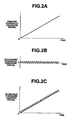
- FIG. 2A is a graph showing the waveform of a primary hydraulic pressure signal of the clutch control system according to one embodiment of the present invention.
- FIG. 2B is a graph showing the waveform of a secondary hydraulic pressure signal of the clutch control system according to one embodiment of the present invention.
- FIG. 2C is a graph showing the waveform of a hydraulic pressure control signal of the clutch control system according to one embodiment of the present invention.
- FIG. 3 is a graph showing secular hydraulic pressure changes in the hydraulic clutch control system according to one embodiment of the present invention.
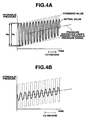
- FIG. 4A is a graph showing hydraulic pressure changes in the hydraulic clutch control system, not during the clutch piston stroke, according to one embodiment of the present invention.
- FIG. 4B is a graph showing hydraulic pressure changes in the hydraulic clutch control system, during the clutch piston stroke, according to one embodiment of the present invention.
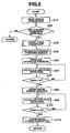
- FIG. 5 is a flowchart for a hydraulic pressure control program of the clutch control system according to one embodiment of the present invention.
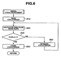
- FIG. 6 is a flowchart for a signal cycle adjustment program of the clutch control system according to one embodiment of the present invention.
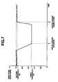
- FIG. 7 is a schematic view showing how to judge the clutch piston stroke according to one embodiment of the present invention.
- FIGS. 8A, 8B, 8C and 8D are graphs showing the cycle period settings of the secondary hydraulic pressure signal according to one embodiment of the present invention.
- FIG. 9 is a schematic view of signal phase shift control of the clutch control system according to a modification of the embodiment of the present invention.
- the hydraulic clutch control system of the present embodiment includes a friction clutch mechanism 1, a hydraulic circuit 7 for supplying a regulated amount of hydraulic oil from an oil pump (as a hydraulic pressure source) to the clutch mechanism 1 through a hydraulic passage 9, a pressure sensor (detection unit) 6 for detecting the pressure of hydraulic oil supplied to the clutch mechanism 1 and an electronic control device 10 for controlling the operations of the hydraulic circuit 7.
- the friction clutch mechanism 1 is designed as a hydraulic multiple disc clutch (also called a wet-type multiple disc clutch) that has hollow input and output shafts 2a and 5a arranged rotatably relative to each other about a clutch shaft axis CL (indicated by a dashed line in FIG. 1 ) and connected to a vehicle engine (or motor) and wheels, respectively, so as to connect and disconnect the transmission of power from the engine to the wheels.
- a hydraulic multiple disc clutch also called a wet-type multiple disc clutch
- the clutch mechanism 1 has a plurality of drive discs 2b (as first rotary elements), a plurality of driven discs 5b (as second rotary elements) with friction plates 5c, a clutch piston 3a, a seal ring 3b and a return spring 4.
- the drive discs 2b and the driven discs 5b are alternately arranged in parallel to one another between the clutch input shaft 2a and the clutch output shaft 5a.
- the drive discs 2b are fitted with an inner surface of the clutch input shaft 2a in such a manner that the drive discs 2b can slide relative to the clutch input shaft 2a along the clutch shaft axis CL and rotate about the clutch shaft axis CL together with the clutch input shaft 2a
- the driven discs 5b are fitted with an outer surface of the clutch output shaft 5a in such a manner that the driven discs 5b can slide relative to the clutch output shaft 5a along the clutch shaft axis CL and rotate about the clutch shaft axis CL together with the clutch output shaft 5a.
- the friction plates 5c are attached to opposite sides of the driven discs 5b and sandwiched between adjacent pairs of the drive discs 2b and the driven discs 5b.
- the clutch piston 3a is slidably disposed between the inner surface of the clutch input shaft 2a and the outer surface of the clutch output shaft 5a.
- a hydraulic chamber 8 in communication with the hydraulic passage 9 so that the clutch piston 3a slides relative to the clutch input shaft 2a and the clutch drive discs 2b along the clutch shaft axis CL in response to the supply of hydraulic oil from the hydraulic circuit 7 into the hydraulic chamber 8 through the hydraulic passage 9.
- the amount of displacement of the clutch piston 3a toward the clutch drive discs 2b increases with the hydraulic oil pressure supplied from the hydraulic circuit 7 into the hydraulic chamber 8 through the hydraulic passage 9.
- the seal ring 3b is held between the sliding surface portions of the clutch input shaft 2a and the clutch piston 3a to provide seal against leakage of the hydraulic oil from the hydraulic chamber 8.
- the clutch piston 3a moves against the tension of the return spring 4 and presses the clutch drive discs 2b in the direction A so as to bring the clutch drive discs 2b into engagement with the clutch driven discs 5b when the hydraulic clutch pressure is set higher than or equal to the given threshold level.
- the clutch piston 3a moves in the direction B by the tension of the return spring 4 so as to disengage the clutch drive discs 2b from the clutch driven discs 5b and prevent the occurrence of a drag torque in the clutch mechanism 1.
- the position of the clutch piston 3a at which there is a clearance of d left between the clutch piston 3a and the clutch drive disc 2b is defined as a "reference position”
- the displacement of the clutch piston 3a from the reference position in the direction A is defined as a "stroke”.
- the clutch piston 3a When the clutch piston 3a is in the reference position (i.e. the stroke of the clutch piston 3a is zero), the amount of clearance between the clutch piston 3a and the clutch drive disc 2b is equal to the length d. While the clutch piston 3a moves in the direction A, the amount of clearance between the clutch piston 3a and the clutch drive disc 2b is given by subtraction of the clutch piston stroke from the length d.
- the clutch mechanism 1 shifts in a so-called partial engagement state (slip state) so as to start power transmission from the clutch input shaft 2a to the clutch output shaft 5a.
- the amount of power transmitted from the clutch input shaft 2a to the clutch output shaft 5a varies depending on the strength of friction between the clutch drive discs 2b and the clutch driven discs 5b, i.e., the strength of force with which the clutch piston 3a presses the clutch drive discs 2b against the clutch driven discs 5b.
- the force of the clutch piston 3a to press the clutch drive discs 2b against the clutch driven discs 5b increases to a given level, there is no difference in rotation speeds between the clutch input shaft 2a and the clutch output shaft 5a so that the clutch mechanism 1 shifts into a complete engagement state.
- the engagement state of the clutch mechanism 1 can be thus controlled according to the hydraulic clutch pressure.
- the hydraulic circuit 7 has a pressure regulation valve operated by the control device 10 to regulate the supply of hydraulic oil into the hydraulic chamber 8 and increase and decrease the hydraulic clutch pressure selectively.
- the pressure sensor 6 is mounted on the hydraulic passage 9 at a location adjacent to the clutch piston 3a so as to detect the pressure of hydraulic oil in the hydraulic passage 9 as the actual value of the hydraulic clutch pressure and output a detection signal responsive to the detected hydraulic pressure value to the control device 10.
- the hydraulic oil pressure detected by the pressure sensor 6 is equal to the hydraulic oil pressure regulated by the hydraulic circuit 7 in a steady state where the clutch piston 3a makes no stroke movement but is not equal to the hydraulic oil pressure regulated by the hydraulic circuit 7 in a non-steady state under the stroke movement of the clutch piston 3a.
- the pressure sensor 6 may alternatively be arranged to detect the pressure of hydraulic oil in the hydraulic chamber 8 as the actual hydraulic clutch pressure value.
- an engine oil temperature sensor 21 to detect an engine oil temperature of the vehicle
- an engine speed sensor 22 to detect an engine speed of the vehicle
- a vehicle speed sensor 23 to detect a traveling speed of the vehicle
- a brake pedal sensor 24 to detect a brake pedal depression of the vehicle.
- the control device 10 includes a primary hydraulic pressure signal generation unit 11, a secondary hydraulic pressure signal generation unit 12, a piston stroke judgment unit 13, a hydraulic pressure control unit 14, a learning unit 15 and a storage unit 16, for learning control of the hydraulic clutch pressure.
- the primary hydraulic pressure signal generation unit 11 generates and outputs a primary hydraulic pressure signal to the hydraulic pressure control unit 14.
- the primary hydraulic pressure signal is used to regulate the magnitude of the hydraulic clutch pressure and determine the position of the clutch piston 3a for detection of the stroke of the clutch piston 3a.
- the intensity (e.g. current or voltage intensity) of the primary hydraulic pressure signal gradually increases with time as shown in FIG. 2A , such that the intensity gradient of the primary hydraulic pressure signal corresponds to the rate of increase of the hydraulic clutch pressure, i.e., the stroke speed of the clutch piston 3a.
- the intensity of the primary hydraulic pressure signal is further set in such a manner that the initial value of the hydraulic clutch pressure provided under the primary hydraulic pressure signal becomes lower than the threshold level.
- the secondary hydraulic pressure signal generation unit 12 generates and outputs a secondary hydraulic pressure signal to the hydraulic pressure control unit 14.
- the secondary hydraulic pressure signal is applied to the primary hydraulic pressure signal so as to allow the utilization of hydraulic pressure transfer characteristics of the clutch mechanism 1 for detection of the stroke of the clutch piston 3a.
- the secondary hydraulic pressure signal can be a wave signal with predetermined amplitude and periodicity. Examples of the wave signal include an alternating signal having a sine waveform or a pulse signal having a square waveform.
- the secondary hydraulic pressure signal is provided in the form of square wave pulses, as shown in FIG. 2B , to easily induce fluctuations in the hydraulic clutch pressure. The pulse amplitude and cycle period of the secondary hydraulic pressure signal are adjusted as will be described later.
- the hydraulic pressure control unit 14 superimposes the primary and secondary hydraulic pressure signals on each other to obtain a hydraulic pressure control signal responsive to the command value of the hydraulic clutch pressure.
- the hydraulic pressure control signal is of pulse waveform as shown in FIG. 2C .
- the hydraulic pressure control unit 14 also operates the hydraulic circuit 7 to increase the hydraulic clutch pressure according to the intensity of the hydraulic pressure control signal.
- the piston stroke judgment unit 13 judges the stroke of the clutch piston 3a based on the amount of fluctuations of the hydraulic clutch pressure.
- the hydraulic clutch pressure gradually increases with vibrational fluctuations under the hydraulic pressure control signal from the hydraulic pressure control unit 14. More specifically, the hydraulic clutch pressure has an average magnitude regulated under the primary hydraulic pressure signal and shows a small amount of fluctuations in response to the pulses of the secondary hydraulic pressure signal.
- the fluctuations of the hydraulic clutch pressure are substantially conserved by virtue of the reaction force of the clutch piston 3a as shown in FIG. 4A in a steady state where the clutch piston 3 is in the reference position with no stroke movement.
- the fluctuations of the hydraulic clutch pressure are absorbed by a volume change in the hydraulic chamber 8 as shown in FIG. 4B in a non-steady state under the stroke movement of the clutch piston 3a due to the fact that some of the energy of such pressure fluctuations is converted into the elastic potential energy of the return spring 4.
- the fluctuations of the actual hydraulic clutch pressure lag behind the fluctuations of the command hydraulic pressure so that the amount of fluctuations of the actual hydraulic clutch pressure apparently decreases during the stroke of the clutch piston 3a.
- the piston stroke judgment unit 13 judges the initiation and completion of the stroke of the clutch piston 3a by comparison of the amplitude (fluctuation amount) of the hydraulic pressure detection signal from the pressure sensor 6 and the amplitude (fluctuation amount) of the secondary hydraulic pressure signal from the secondary hydraulic pressure signal generation unit 12 or the hydraulic pressure control signal from the hydraulic pressure control unit 14. There is no to perform an arithmetic operation/computation such as differentiation susceptible to pressure noise in the present embodiment. It is thus possible to detect the stroke of the clutch piston 3a and learn the clutch engagement point easily and accurately at any time before the complete engagement of the clutch mechanism 1, without regard to the magnitude of the hydraulic clutch pressure (i.e.
- the signal intensities so as to determine the hydraulic pressure to be exerted to complete the stroke of the clutch piston 3a and start the power transmission properly and achieve system simplification and versatility improvements.
- the control of the hydraulic clutch pressure under the wave signal allows easy and accurate detection of the periodic hydraulic clutch oil response and provides improvements in stroke judgment accuracy and system simplification and controllability.
- the piston stroke judgment unit 13 determines the amplitude Pa of the hydraulic pressure detection signal from the pressure sensor 6 and the amplitude Pb of the hydraulic pressure control signal from the hydraulic pressure control unit 14, calculates a ratio of the amplitude Pa of the hydraulic pressure detection signal to the amplitude Pb of the hydraulic pressure control signal, and then, judges the stroke of the clutch piston 3a according to the calculated amplitude ratio Pa / Pb in the present embodiment.
- the amplitude Pa of the hydraulic pressure detection signal becomes small relative to the amplitude Pb of the hydraulic pressure control signal as explained above so that the amplitude ratio Pa / Pb decreases considerably.
- the piston stroke judgment unit 13 is then allowed to easily judge that clutch piston 3a is making a stroke movement when the amplitude ratio Pa / Pb is lower than 1 and that the clutch piston 3a is making no stroke movement when the amplitude ratio Pa / Pb is substantially 1.
- the piston stroke judgment unit 13 judges the initiation of the stroke movement of the clutch piston 3a at the time when the amplitude ratio Pa / Pb becomes lower than a first threshold value H1 and to judge the completion of the stroke movement of the clutch piston 3 a at the time when the amplitude ratio Pa / Pb becomes increased to or exceeds a second threshold value H2.
- the threshold values H1 and H2 are herein set in such a manner as to satisfy the relationship of H1 ⁇ H2 ⁇ 1.
- the initiation of the stroke of the clutch piston 3a (to start eliminating the clearance between the clutch piston 3a and the clutch drive disc 2b) and the completion of the stroke of the clutch piston 3a (to start transmitting the power through the clutch mechanism 1 upon shifting from the clutch disengagement state into the partial engagement state) can be judged easily and accurately by monitoring the hydraulic clutch pressure continuously from before the initiation of the stroke of the clutch piston 3a until after the completion of the stroke of the clutch piston 3a.
- the piston stroke judgment unit 13 causes the hydraulic pressure control unit 14 to stop the hydraulic circuit 7 and terminate the learning control of the hydraulic clutch pressure upon judging the completion of the stroke of the clutch piston 3a. This makes it possible to detect the stroke of the clutch piston 3a and learn the clutch engagement point assuredly before the complete engagement of the clutch mechanism 1.
- the learning unit 15 learns the values of the hydraulic clutch pressure (provided under the primary hydraulic pressure signal or the hydraulic pressure detection signal) at the time of initiation and completion of the stroke of the clutch piston 3a based on the judgment results of the piston stroke judgment unit 13 and stores these piston stroke initiation and completion points in the storage unit 15 for reference to various control operations such as vehicle drive/shift control.
- the learning unit 15 judges the satisfaction of learning conditions based on the input about various vehicle operation parameters such as clutch torque transmission, engine oil temperature, engine speed, vehicle speed and/or brake pedal depression from the sensors 6 and 21 to 24. When the learning conditions are satisfied, the learning unit 15 learns the piston stroke initiation and completion points. On the other hand, the learning unit 15 causes the hydraulic pressure control unit 14 to stop the hydraulic circuit 7 and interrupt the learning control of the hydraulic clutch pressure when the learning conditions are not satisfied. It is herein an essential condition that the clutch mechanism 1 is not in a torque transmitting state. Examples of the other learning conditions are that: (1) the engine oil temperature is stable within a predetermined temperature range; (2) the engine speed is stable without fluctuations (i.e.
- the storage unit 16 stores therein the hydraulic clutch pressure values learned by the learning unit 15 upon judging the initiation and completion of the stroke of the clutch piston 3a so that these values can be referred to in any other control operations (such as vehicle drive/shift control).
- the storage unit 16 also stores, as an interrupted hydraulic pressure signal, the intensity of the primary hydraulic pressure signal responsive to the value of the hydraulic clutch pressure when the learning unit 15 judges that the learning conditions are not satisfied, and then, outputs the interrupted hydraulic pressure signal to the hydraulic pressure control unit 14 when the learning unit 15 judges that the learning conditions are satisfied again.
- the hydraulic pressure control unit 14 reconstitutes the hydraulic pressure control signal by superimposing of the interrupted hydraulic pressure signal and the secondary hydraulic pressure signal and thereby continues the interrupted learning control of the hydraulic clutch pressure.
- the learning time can be shortened at the restart of the learning control of the hydraulic clutch pressure.
- the amplitude of the secondary hydraulic pressure signal is adjusted to a level capable of inducing hydraulic pressure fluctuations greater than a minimum detectable pressure change of the pressure sensor 6 but not so large that the stroke of the clutch piston 3a becomes caused (initiated or completed) by the hydraulic pressure fluctuations induced under the secondary hydraulic pressure signal for assured detection of change of the hydraulic clutch pressure response characteristic even during the stroke of the clutch piston 3a.
- the supply of the hydraulic clutch pressure is stopped upon completion of the stroke of the clutch piston 3a as explained above, so that the clutch mechanism 1 would output a small amount of torque during a time period between the instant when the clutch mechanism 1 shifts in the partial engagement state by completion of the stroke of the piston stroke 3a and the instant when the supply of the hydraulic clutch pressure comes to a full stop.
- the amplitude of the hydraulic pressure control signal the amplitude of the secondary hydraulic pressure signal
- the engagement of the clutch mechanism 1 becomes strengthened to cause an increase in the amount of torque outputted from the clutch mechanism 1 during such a time period before the stop of the hydraulic clutch pressure supply.
- the amplitude of the secondary hydraulic pressure signal can be set in such a manner that the fluctuation amplitude (e.g.
- 20 kPa) of the hydraulic clutch pressure caused by the secondary hydraulic pressure signal is approximately equivalent to one-tenth of the initial value (e.g. 180 kPa) of the hydraulic clutch pressure provided under the primary hydraulic pressure signal, thereby limiting the acceleration exerted on the vehicle by torque transmission immediately after the engagement of the clutch mechanism 1 (immediately after the completion of the stroke of the clutch piston 3a) to less than 0.03G. This makes it possible to detect the stroke of the clutch piston 3a while protecting the vehicle driver from discomfort even in a situation that the engine torque is transmitted to the clutch output side.
- the secondary hydraulic pressure signal generation unit 12 includes a signal cycle setting section 17 and a signal cycle check section 18 as shown in FIG. 1 , so as to adjust the cycle period of the secondary hydraulic pressure signal appropriately within a time period where the learning conditions are satisfied during unexecution of the learning control of the hydraulic clutch pressure (before the start of the learning control of the hydraulic clutch pressure).
- the cycle period of the secondary hydraulic pressure signal is preferably set in such a manner that half the cycle period of the secondary hydraulic pressure signal is equal in length to the response lag time t of the hydraulic clutch pressure under no stroke movement of the clutch piston 3a as shown in FIGS. 8A and 8B .
- the response lag time t is a measure of the rate of change of the hydraulic clutch pressure response lag (corresponding to the time constant of the hydraulic clutch pressure), which is independent of the amplitude of the secondary hydraulic pressure signal.
- the fluctuations of the hydraulic clutch pressure are conserved and detected by the pressure sensor 6 in a steady state where the stroke of the clutch piston 3a is zero.
- the fluctuations of the hydraulic clutch pressure cannot be detected adequately even in such a steady state due to various factors (e.g. the viscosity and density variations of the hydraulic oil due to oil temperature changes, the configuration of the hydraulic passage 9 and the arrangement position of the pressure sensor 6) when the cycle period (the inverse of the frequency) of the secondary hydraulic pressure signal is too long or too short.
- the cycle period t1 of the secondary hydraulic pressure signal is too long relative to the response lag time t of the hydraulic clutch pressure as shown in FIG. 8C .
- the signal cycle setting section 17 generates a reference hydraulic pressure signal by setting the pulse cycle of the reference hydraulic signal to a sufficiently short degree that the fluctuations of the hydraulic clutch pressure cannot be detected by the pressure sensor 6 adequately in a steady state under no stroke movement of the clutch piston 3a.
- the signal cycle setting section 17 then outputs the reference hydraulic pressure signal to the hydraulic pressure control unit 14 and causes the hydraulic pressure control unit 14 to control the hydraulic clutch pressure according to the reference hydraulic pressure signal only.
- the signal cycle check section 18 checks whether or not the reference pulse signal cycle is appropriate as the cycle period of the second hydraulic pressure signal by amplitude comparison of the hydraulic pressure detection signal from the pressure sensor 6 and the reference hydraulic pressure signal from the signal cycle setting section 17.
- the amplitude of the reference hydraulic pressure signal is identical to that of the hydraulic pressure control signal. The appropriateness of the pulse signal cycle can be thus judged by amplitude comparison of the hydraulic pressure detection signal and the hydraulic pressure control signal.
- the signal cycle check section 18 determines the amplitude Pa' of the hydraulic pressure detection signal and the amplitude Pb of the reference hydraulic pressure signal, calculates a ratio of the amplitude Pa' of the hydraulic pressure detection signal to the amplitude Pb of the reference hydraulic pressure signal, and then judges the appropriateness of the pulse signal cycle according to the calculated amplitude ratio Pa' l Pb.
- the signal cycle check section 18 judges that the reference pulse signal cycle is not appropriate as the cycle period of the secondary hydraulic pressure signal and causes the signal cycle setting section 17 to gradually increase the reference pulse signal cycle to an appropriate level.
- the signal cycle check unit 18 judges that the reference pulse signal cycle is appropriate as the cycle period of the secondary hydraulic pressure signal and causes the signal cycle setting section 17 to adopt the current pulse signal cycle as the cycle period of the secondary hydraulic pressure signal.
- the above learning control routine of the hydraulic clutch pressure is performed by the following procedure shown in FIG. 5 in the present embodiment.
- step A10 the control device 10 enables the learning unit 15 to read various vehicle operation parameters from the sensors 6 and 21 to 24.
- step A20 the control device 10 enables the learning unit 15 to judge whether the learning conditions are satisfied or not. If the learning conditions are not satisfied (No in step A20), the control exits process routine. If the learning conditions are satisfied (Yes in step A20), the control proceeds to step A30.
- step A30 the control unit 10 enables the second hydraulic pressure signal generation unit 12 to adjust the cycle period of the secondary hydraulic pressure signal appropriately through the execution of a signal cycle adjustment subroutine.
- step A40 the control device 10 enables the primary and secondary hydraulic pressure signal generation units 11 and 12 to output the primary and secondary hydraulic pressure signals to the hydraulic pressure control unit 14, respectively.
- the control device 10 alternatively enables the storage unit 16 to output the interrupted hydraulic pressure signal to the hydraulic pressure control unit 14.
- step A50 the control device 10 enables the hydraulic pressure control unit 14 to generate the hydraulic pressure control signal by superimposing of the primary hydraulic pressure signal (or the interrupted hydraulic pressure signal) and the secondary hydraulic pressure signal, and then, to operate the hydraulic circuit 7 in such a manner as to control the hydraulic clutch pressure according to the hydraulic pressure control signal.
- step A60 the control device 10 enables the piston stroke judgment unit 13 to determine the amplitude Pa of the hydraulic pressure detection signal and the amplitude Pb of the hydraulic pressure control signal and to calculate the amplitude ratio Pa / Pb.
- step A70 the control device 10 enables the piston stroke judgment unit 13 to decide whether the amplitude ratio Pa / Pb is lower than the first threshold value H1 (H1 ⁇ 1). If Pa / Pb ⁇ H1 (No in step A70), the control goes back to step A60. If Pa / Pb ⁇ H1 (Yes in step A70), the control proceeds to step A80.
- the amount of fluctuations of the actual hydraulic clutch pressure decreases so that the amplitude ratio Pa / Pb becomes lower as shown in FIG. 7 immediately before the initiation of the stroke of the clutch piston 3a.
- the initiation of the stroke of the clutch piston 3 a can be thus judged when the amplitude ratio Pa / Pb becomes lower than the first threshold value H1.
- the control device 10 Upon judging the initiation of the stroke of the clutch piston 3a, the control device 10 enables in step A80 the learning unit 15 to learn the value of the hydraulic clutch pressure at the time of initiation of the stroke of the clutch piston 3a and store this hydraulic pressure value in the storage unit 16.
- step A90 the control device 10 enables the piston stroke judgment unit 13 to determine the amplitude Pa of the hydraulic pressure detection signal and the amplitude Pb of the hydraulic pressure control signal and to calculate the amplitude ratio Pa / Pb. It is noted that the amount of fluctuations of the actual hydraulic clutch pressure is kept small during the stroke of the clutch piston 3a so that the amplitude ratio Pa / Pb is lower than 1 in this routine step.
- step A100 the control device 10 enables the piston stroke judgment unit 13 to decide whether the amplitude ratio Pa / Pb is higher than the second threshold value H2. If Pa l Pb ⁇ H2 (Yes in step A100), the control goes back to step A90. If Pa / Pb ⁇ H2 (No in step A100), the control proceeds to step A110.
- the amount of fluctuations of the actual hydraulic clutch pressure increases so that the amplitude ratio Pa / Pb becomes higher as shown in FIG. 7 immediately before the completion of the stroke of the clutch piston 3a.
- the completion of the stroke of the clutch piston 3a can be thus judged when the amplitude ratio Pa / Pb becomes higher than or equal to the second threshold value H2.
- control device 10 Upon judging the completion of the stroke of the clutch piston 3a, the control device 10 enables in step A110 the learning unit 15 to learn the value of the hydraulic clutch pressure at the time of completion of the stroke of the clutch piston 3a and store this hydraulic pressure value in the storage unit 16.
- control device 10 is able to judge the initiation and completion timings of the stroke of the clutch piston 3a, detect the engagement point of the clutch mechanism 1 and determine the hydraulic pressure to be exerted on the clutch piston 3a to complete the clutch piston idle stroke and start the power transmission easily and accurately with a simple and versatile device configuration.
- the signal cycle adjustment subroutine is performed by the following procedure shown in FIG. 6 in the present embodiment.
- step B 10 the secondary hydraulic pressure signal generation unit 12 enables the signal cycle setting section 17 to read the pulse cycle period of the reference hydraulic pressure signal.
- the reference pulse signal cycle read by the signal cycle setting section 17 in this routine step is the initial cycle period value of the reference hydraulic pressure signal or the cycle period value of the reference hydraulic pressure signal set in the preceding signal cycle adjustment subroutine.
- step B20 the secondary hydraulic pressure signal generation unit 12 enables the signal cycle check section 18 to determine the amplitude Pa' of the hydraulic pressure detection signal and the amplitude Pb of the reference hydraulic pressure signal and to calculate the amplitude ratio Pa' / Pb.
- step B30 the secondary hydraulic pressure signal generation unit 12 enables the signal cycle check section 18 checks whether the amplitude ratio Pa' / Pb is higher than or equal to 1. If Pa' l Pb ⁇ 1 (Yes in step B30), the control proceeds to step B40. If Pa' / Pb ⁇ 1 (No in step B30), the control proceeds to step B50.
- step B40 the secondary hydraulic pressure signal generation unit 12 enables the signal cycle check section 18 to determine that the reference pulse signal cycle is not appropriate to the cycle period of the secondary hydraulic pressure signal and enables the signal cycle setting section 17 to adjust the reference pulse signal cycle to a longer value. The control then goes back to step B20.
- step B50 the secondary hydraulic pressure signal generation unit 12 enables the signal cycle check section 18 to determine that the reference pulse signal cycle is appropriate to the cycle period of the secondary hydraulic pressure signal and enables the signal cycle setting section 17 to set the reference pulse signal cycle to the cycle period of the secondary hydraulic pressure signal.
- the secondary hydraulic pressure signal generation unit 12 is allowed to adjust the cycle period of the secondary hydraulic pressure signal easily and appropriately in such a manner that half the cycle period of the secondary hydraulic pressure signal is equal in length to the response lag time t of the hydraulic clutch pressure under no stroke movement of the clutch piston 3a.
- the learning control of the hydraulic clutch pressure can be applied even when the clutch mechanism 1 is of any type of hydraulic clutch other than the multiple disc clutch.
- the clutch mechanism 1 may alternatively be designed as a double clutch assembly with clutches, each of which is structured as shown in FIG. 1 .
- the hydraulic circuit 7 supplies hydraulic pressures to cause strokes of the pistons 3a for engagement of the clutches, respectively;
- the primary hydraulic signal generation unit 11 generates primary hydraulic pressure signals to regulates the magnitudes of the hydraulic clutch pressures, respectively;
- the second hydraulic signal generation unit 12 generates secondary hydraulic pressure signals to cause fluctuations in the hydraulic clutch pressures, respectively;
- the hydraulic pressure control unit 14 operate the hydraulic circuit 7 to control the hydraulic clutch pressures according to the hydraulic pressure control signals, respectively;
- the detection unit is provided with pressure sensors 6 to detect the amounts of fluctuations of the hydraulic clutch pressures, respectively; and the piston stroke judgment unit 13 judges the strokes of the clutch pistons 3a based on the amounts of fluctuations of the hydraulic clutch pressures, respectively.
- the learning control of the hydraulic clutch pressure can be continuously performed for detection of the clutch piston idle stroke in the unactuated side of the clutch units of the double clutch. It is further desirable that the second hydraulic pressure signals are phase shifted to each other, as shown in FIG. 9 , in order to prevent interference between the second hydraulic pressure signals i.e. between the hydraulic pressure control signals and judge the stroke of each clutch piston 3a with improved accuracy.
- the secondary hydraulic pressure signal is not necessarily a wave signal with predetermined amplitude and periodicity and can be provided in any form that allows the utilization of the hydraulic pressure transfer characteristics of the clutch mechanism 1 for detection of the stroke of the clutch piston 3a.
- control device 10 may alternatively be configured to allow the piston stroke judgment unit 13 to judge the stoke of the clutch piston 3a as occasion requires.
- the technique of adjusting the cycle period of the secondary hydraulic pressure signal is not particularly restricted, and the cycle period of the secondary hydraulic pressure signal can be adjusted by any other appropriate method.
- the reference pulse signal cycle may be initially set to a sufficiently large degree and gradually decreased to an appropriate degree although the reference pulse signal cycle is initially set to a sufficiently small degree and gradually increased to an appropriate degree in the present embodiment.
- the pulse signal cycle may be increased or decreased stepwisely.
- the appropriateness of the pulse signal cycle is judged depending on whether the amplitude ratio Pa' / Pb is 1 or not in the present embodiment, it is alternatively possible to judge that the pulse signal cycle is appropriate when the amplitude ratio Pa' l Pb becomes higher than or equal to a threshold value H3 ( H3 ⁇ 1) in view of variations of the hydraulic pressure characteristics and detection errors of the pressure sensor 6.
Landscapes
- Engineering & Computer Science (AREA)
- General Engineering & Computer Science (AREA)
- Mechanical Engineering (AREA)
- Physics & Mathematics (AREA)
- Fluid Mechanics (AREA)
- Hydraulic Clutches, Magnetic Clutches, Fluid Clutches, And Fluid Joints (AREA)
Description
- The present invention relates to a hydraulic clutch control system and method.
- An automotive vehicle has a clutch mechanism arranged on a power transmission line to selectively connect and disconnect the transmission of power from a vehicle engine (such as internal combustion engine) or electric motor to wheels under vehicle drive/shift control. There are some types of clutch mechanisms including a friction clutch in which rotary elements are engaged to allow power transmission due to friction between the rotary elements. One example of friction clutch is known as a multiple disc clutch. The multiple disc clutch has first and second rotary elements and a clutch piston actuated by hydraulic pressure to press the first rotary elements against the second rotary elements and thereby engage these rotary elements such that the degree of engagement of the rotary elements can be controlled according to the hydraulic pressure on the clutch piston. The multiple disc clutch also has a return spring to bias the clutch piston apart from the rotary elements and leave some clearance between the clutch piston and the rotary element for complete disengagement of the rotary elements when the hydraulic clutch pressure becomes decreased to a certain level. In the case that the multiple disc clutch starts from such a complete disengagement state, the rotary elements cannot be engaged until the clutch piston comes into contact with the rotary element i.e. during a so-called idle stroke of the clutch piston. This results in slow clutch response.
- Thus, it has become conventional to detect the amount of clearance between the clutch piston and the rotary element, calculate the hydraulic pressure to be exerted on the clutch piston to eliminate the detected clearance and complete the clutch piston idle stroke, and then, reflect the calculated value of the hydraulic clutch pressure in actual clutch control operation.
-
Japanese Patent No. 2595812 JP-A-04201727 Japanese Patent No. 2595812 - In the above-disclosed control device, however, the timing of completion of the clutch piston idle stroke is determined as a point at which the second-order differentiation result of the hydraulic clutch pressure becomes maximized before the first-order differentiation result of the hydraulic clutch pressure reaches zero. Namely, the timing of completion of the clutch piston idle stroke cannot be judged until the clutch shifts from a partial engagement state (slip state) into a complete engagement state where clutch disc engagement produces no effect on the other part of the vehicle drive train. The control device is thus poor in versatility. Further, the second-order differentiation result of the hydraulic clutch pressure is susceptible to pressure fluctuation noise so that the clutch piston idle stroke cannot be always detected accurately in the disclosed control device.
- It is therefore an object of the present invention to provide a hydraulic clutch control system and method for detecting a clutch piston idle stroke so as to determine a hydraulic pressure to be exerted to complete the clutch piston idle stroke and start power transmission accurately without the need for clutch complete engagement.
- According to the present invention, there is provided a hydraulic clutch control system, comprising: a clutch; a hydraulic circuit that supplies a hydraulic pressure to a piston of the clutch so as to cause a stroke of the piston for engagement of the clutch; a primary hydraulic pressure signal generation unit that generates a primary hydraulic pressure signal to regulate a magnitude of the hydraulic pressure; a secondary hydraulic pressure signal generation unit that generates a secondary hydraulic pressure signal to induce fluctuations in the hydraulic pressure; a hydraulic pressure control unit that operates the hydraulic circuit to control the hydraulic pressure according to the primary and secondary hydraulic pressure signals; a detection unit that detects the amount of fluctuations in the hydraulic pressure; and a piston stroke judgment unit that judges the piston stroke based on the hydraulic pressure fluctuation amount.
- According to the present invention, there is provided a hydraulic clutch control method, comprising: supplying a hydraulic pressure to a clutch to cause a clutch piston stroke for engagement of the clutch; generating a primary hydraulic pressure signal to regulate a magnitude of the hydraulic pressure; generating a secondary hydraulic pressure signal to induce fluctuations in the hydraulic pressure; controlling the hydraulic pressure according to the primary and secondary hydraulic pressure signals; detecting the amount of fluctuations in the hydraulic pressure; and judging the clutch piston stroke based on the hydraulic pressure fluctuation amount.
- The other objects and features of the present invention will also become understood from the following description.
-
FIG. 1 is a schematic view of a hydraulic clutch control system according to one embodiment of the present invention. -
FIG. 2A is a graph showing the waveform of a primary hydraulic pressure signal of the clutch control system according to one embodiment of the present invention. -
FIG. 2B is a graph showing the waveform of a secondary hydraulic pressure signal of the clutch control system according to one embodiment of the present invention. -
FIG. 2C is a graph showing the waveform of a hydraulic pressure control signal of the clutch control system according to one embodiment of the present invention. -
FIG. 3 is a graph showing secular hydraulic pressure changes in the hydraulic clutch control system according to one embodiment of the present invention. -
FIG. 4A is a graph showing hydraulic pressure changes in the hydraulic clutch control system, not during the clutch piston stroke, according to one embodiment of the present invention. -
FIG. 4B is a graph showing hydraulic pressure changes in the hydraulic clutch control system, during the clutch piston stroke, according to one embodiment of the present invention. -
FIG. 5 is a flowchart for a hydraulic pressure control program of the clutch control system according to one embodiment of the present invention. -
FIG. 6 is a flowchart for a signal cycle adjustment program of the clutch control system according to one embodiment of the present invention. -
FIG. 7 is a schematic view showing how to judge the clutch piston stroke according to one embodiment of the present invention -
FIGS. 8A, 8B, 8C and 8D are graphs showing the cycle period settings of the secondary hydraulic pressure signal according to one embodiment of the present invention. -
FIG. 9 is a schematic view of signal phase shift control of the clutch control system according to a modification of the embodiment of the present invention. - The present invention will be described below in detail with reference to the drawings. The following embodiment of the present invention specifically refers to a hydraulic clutch control system for an automotive vehicle.
- Referring to
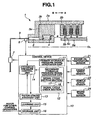
FIG. 1 , the hydraulic clutch control system of the present embodiment includes afriction clutch mechanism 1, a hydraulic circuit 7 for supplying a regulated amount of hydraulic oil from an oil pump (as a hydraulic pressure source) to theclutch mechanism 1 through ahydraulic passage 9, a pressure sensor (detection unit) 6 for detecting the pressure of hydraulic oil supplied to theclutch mechanism 1 and anelectronic control device 10 for controlling the operations of the hydraulic circuit 7. - In the present embodiment, the
friction clutch mechanism 1 is designed as a hydraulic multiple disc clutch (also called a wet-type multiple disc clutch) that has hollow input andoutput shafts FIG. 1 ) and connected to a vehicle engine (or motor) and wheels, respectively, so as to connect and disconnect the transmission of power from the engine to the wheels. It is noted that, as theclutch mechanism 1 is substantially symmetrical about the clutch shaft axis CL, only half part of theclutch mechanism 1 along the clutch shaft axis CL is shown inFIG. 1 . - The
clutch mechanism 1 has a plurality ofdrive discs 2b (as first rotary elements), a plurality of drivendiscs 5b (as second rotary elements) withfriction plates 5c, aclutch piston 3a, aseal ring 3b and a return spring 4. - The
drive discs 2b and the drivendiscs 5b are alternately arranged in parallel to one another between theclutch input shaft 2a and theclutch output shaft 5a. Thedrive discs 2b are fitted with an inner surface of theclutch input shaft 2a in such a manner that thedrive discs 2b can slide relative to theclutch input shaft 2a along the clutch shaft axis CL and rotate about the clutch shaft axis CL together with theclutch input shaft 2a, whereas the drivendiscs 5b are fitted with an outer surface of theclutch output shaft 5a in such a manner that the drivendiscs 5b can slide relative to theclutch output shaft 5a along the clutch shaft axis CL and rotate about the clutch shaft axis CL together with theclutch output shaft 5a. Thefriction plates 5c are attached to opposite sides of the drivendiscs 5b and sandwiched between adjacent pairs of thedrive discs 2b and the drivendiscs 5b. - The
clutch piston 3a is slidably disposed between the inner surface of theclutch input shaft 2a and the outer surface of theclutch output shaft 5a. There is defined ahydraulic chamber 8 in communication with thehydraulic passage 9 so that theclutch piston 3a slides relative to theclutch input shaft 2a and theclutch drive discs 2b along the clutch shaft axis CL in response to the supply of hydraulic oil from the hydraulic circuit 7 into thehydraulic chamber 8 through thehydraulic passage 9. In the present embodiment, the amount of displacement of theclutch piston 3a toward theclutch drive discs 2b (in the direction A inFIG. 1 ) increases with the hydraulic oil pressure supplied from the hydraulic circuit 7 into thehydraulic chamber 8 through thehydraulic passage 9. Theseal ring 3b is held between the sliding surface portions of theclutch input shaft 2a and theclutch piston 3a to provide seal against leakage of the hydraulic oil from thehydraulic chamber 8. - The return spring 4 is disposed between the
clutch input shaft 2a and theclutch piston 3a to bias theclutch piston 3a apart from theclutch drive discs 2b (in the direction B inFIG. 1 ). The strength of tension of the return spring 4 is adjusted in such a manner that theclutch piston 3a becomes fully biased in the direction B to leave a clearance of d between theclutch piston 3a and theclutch drive disc 2b when the hydraulic oil pressure supplied into thehydraulic chamber 8 and exerted on theclutch piston 3a (hereinafter referred to as the "hydraulic clutch pressure") is lower than a given threshold level. - With such an arrangement, the
clutch piston 3a moves against the tension of the return spring 4 and presses theclutch drive discs 2b in the direction A so as to bring theclutch drive discs 2b into engagement with the clutch drivendiscs 5b when the hydraulic clutch pressure is set higher than or equal to the given threshold level. Upon engagement of theclutch discs clutch input shaft 2a to theclutch output shaft 5a is allowed due to friction resistance between theclutch drive discs 2b and thefriction plates 5c. When the hydraulic clutch pressure is set lower than the given threshold level, theclutch piston 3a moves in the direction B by the tension of the return spring 4 so as to disengage theclutch drive discs 2b from the clutch drivendiscs 5b and prevent the occurrence of a drag torque in theclutch mechanism 1. - Herein, the position of the
clutch piston 3a at which there is a clearance of d left between theclutch piston 3a and theclutch drive disc 2b is defined as a "reference position", and the displacement of theclutch piston 3a from the reference position in the direction A is defined as a "stroke". - When the
clutch piston 3a is in the reference position (i.e. the stroke of theclutch piston 3a is zero), the amount of clearance between theclutch piston 3a and theclutch drive disc 2b is equal to the length d. While theclutch piston 3a moves in the direction A, the amount of clearance between theclutch piston 3a and theclutch drive disc 2b is given by subtraction of the clutch piston stroke from the length d. When the clutch piston 3 comes into contact with theclutch drive disc 2b (i.e. the stroke of the clutch piston 3 becomes equal to the length d) to leave no clearance between theclutch piston 3a and theclutch drive disc 2b, theclutch mechanism 1 shifts in a so-called partial engagement state (slip state) so as to start power transmission from theclutch input shaft 2a to theclutch output shaft 5a. - In the
clutch mechanism 1, the amount of power transmitted from theclutch input shaft 2a to theclutch output shaft 5a varies depending on the strength of friction between theclutch drive discs 2b and the clutch drivendiscs 5b, i.e., the strength of force with which theclutch piston 3a presses theclutch drive discs 2b against the clutch drivendiscs 5b. When the force of theclutch piston 3a to press theclutch drive discs 2b against the clutch drivendiscs 5b increases to a given level, there is no difference in rotation speeds between theclutch input shaft 2a and theclutch output shaft 5a so that theclutch mechanism 1 shifts into a complete engagement state. The engagement state of theclutch mechanism 1 can be thus controlled according to the hydraulic clutch pressure. - The hydraulic circuit 7 has a pressure regulation valve operated by the
control device 10 to regulate the supply of hydraulic oil into thehydraulic chamber 8 and increase and decrease the hydraulic clutch pressure selectively. - The
pressure sensor 6 is mounted on thehydraulic passage 9 at a location adjacent to theclutch piston 3a so as to detect the pressure of hydraulic oil in thehydraulic passage 9 as the actual value of the hydraulic clutch pressure and output a detection signal responsive to the detected hydraulic pressure value to thecontrol device 10. In the present embodiment, the hydraulic oil pressure detected by thepressure sensor 6 is equal to the hydraulic oil pressure regulated by the hydraulic circuit 7 in a steady state where theclutch piston 3a makes no stroke movement but is not equal to the hydraulic oil pressure regulated by the hydraulic circuit 7 in a non-steady state under the stroke movement of theclutch piston 3a. Thepressure sensor 6 may alternatively be arranged to detect the pressure of hydraulic oil in thehydraulic chamber 8 as the actual hydraulic clutch pressure value. - There are further provided an engine
oil temperature sensor 21 to detect an engine oil temperature of the vehicle, anengine speed sensor 22 to detect an engine speed of the vehicle, avehicle speed sensor 23 to detect a traveling speed of the vehicle and abrake pedal sensor 24 to detect a brake pedal depression of the vehicle. These detection values are also outputted to thecontrol device 10. - Referring again to
FIG. 1 , thecontrol device 10 includes a primary hydraulic pressuresignal generation unit 11, a secondary hydraulic pressuresignal generation unit 12, a pistonstroke judgment unit 13, a hydraulicpressure control unit 14, alearning unit 15 and astorage unit 16, for learning control of the hydraulic clutch pressure. - The primary hydraulic pressure
signal generation unit 11 generates and outputs a primary hydraulic pressure signal to the hydraulicpressure control unit 14. The primary hydraulic pressure signal is used to regulate the magnitude of the hydraulic clutch pressure and determine the position of theclutch piston 3a for detection of the stroke of theclutch piston 3a. In the present embodiment, the intensity (e.g. current or voltage intensity) of the primary hydraulic pressure signal gradually increases with time as shown inFIG. 2A , such that the intensity gradient of the primary hydraulic pressure signal corresponds to the rate of increase of the hydraulic clutch pressure, i.e., the stroke speed of theclutch piston 3a. The intensity of the primary hydraulic pressure signal is further set in such a manner that the initial value of the hydraulic clutch pressure provided under the primary hydraulic pressure signal becomes lower than the threshold level. - The secondary hydraulic pressure
signal generation unit 12 generates and outputs a secondary hydraulic pressure signal to the hydraulicpressure control unit 14. The secondary hydraulic pressure signal is applied to the primary hydraulic pressure signal so as to allow the utilization of hydraulic pressure transfer characteristics of theclutch mechanism 1 for detection of the stroke of theclutch piston 3a. For example, the secondary hydraulic pressure signal can be a wave signal with predetermined amplitude and periodicity. Examples of the wave signal include an alternating signal having a sine waveform or a pulse signal having a square waveform. In the present embodiment, the secondary hydraulic pressure signal is provided in the form of square wave pulses, as shown inFIG. 2B , to easily induce fluctuations in the hydraulic clutch pressure. The pulse amplitude and cycle period of the secondary hydraulic pressure signal are adjusted as will be described later. - The hydraulic
pressure control unit 14 superimposes the primary and secondary hydraulic pressure signals on each other to obtain a hydraulic pressure control signal responsive to the command value of the hydraulic clutch pressure. The hydraulic pressure control signal is of pulse waveform as shown inFIG. 2C . The hydraulicpressure control unit 14 also operates the hydraulic circuit 7 to increase the hydraulic clutch pressure according to the intensity of the hydraulic pressure control signal. - The piston
stroke judgment unit 13 judges the stroke of theclutch piston 3a based on the amount of fluctuations of the hydraulic clutch pressure. - As shown in
FIGS. 3 ,4A and 4B , the hydraulic clutch pressure gradually increases with vibrational fluctuations under the hydraulic pressure control signal from the hydraulicpressure control unit 14. More specifically, the hydraulic clutch pressure has an average magnitude regulated under the primary hydraulic pressure signal and shows a small amount of fluctuations in response to the pulses of the secondary hydraulic pressure signal. - The fluctuations of the hydraulic clutch pressure are substantially conserved by virtue of the reaction force of the
clutch piston 3a as shown inFIG. 4A in a steady state where the clutch piston 3 is in the reference position with no stroke movement. However, the fluctuations of the hydraulic clutch pressure are absorbed by a volume change in thehydraulic chamber 8 as shown inFIG. 4B in a non-steady state under the stroke movement of theclutch piston 3a due to the fact that some of the energy of such pressure fluctuations is converted into the elastic potential energy of the return spring 4. The fluctuations of the actual hydraulic clutch pressure lag behind the fluctuations of the command hydraulic pressure so that the amount of fluctuations of the actual hydraulic clutch pressure apparently decreases during the stroke of theclutch piston 3a. When theclutch piston 3a comes into contact with theclutch drive disc 2b, the fluctuations of the hydraulic clutch pressure are substantially conserved by virtue of the reaction force of theclutch drive disc 2b as shown inFIG. 4A . The response lag of the actual hydraulic clutch pressure relative to the command hydraulic pressure becomes cancelled to recover the amount of fluctuations of the hydraulic clutch pressure upon completion of the stroke of theclutch piston 3a. - According to such hydraulic pressure transfer characteristics, the piston
stroke judgment unit 13 judges the initiation and completion of the stroke of theclutch piston 3a by comparison of the amplitude (fluctuation amount) of the hydraulic pressure detection signal from thepressure sensor 6 and the amplitude (fluctuation amount) of the secondary hydraulic pressure signal from the secondary hydraulic pressuresignal generation unit 12 or the hydraulic pressure control signal from the hydraulicpressure control unit 14. There is no to perform an arithmetic operation/computation such as differentiation susceptible to pressure noise in the present embodiment. It is thus possible to detect the stroke of theclutch piston 3a and learn the clutch engagement point easily and accurately at any time before the complete engagement of theclutch mechanism 1, without regard to the magnitude of the hydraulic clutch pressure (i.e. the signal intensities), so as to determine the hydraulic pressure to be exerted to complete the stroke of theclutch piston 3a and start the power transmission properly and achieve system simplification and versatility improvements. In particular, the control of the hydraulic clutch pressure under the wave signal allows easy and accurate detection of the periodic hydraulic clutch oil response and provides improvements in stroke judgment accuracy and system simplification and controllability. - More specifically, the piston
stroke judgment unit 13 determines the amplitude Pa of the hydraulic pressure detection signal from thepressure sensor 6 and the amplitude Pb of the hydraulic pressure control signal from the hydraulicpressure control unit 14, calculates a ratio of the amplitude Pa of the hydraulic pressure detection signal to the amplitude Pb of the hydraulic pressure control signal, and then, judges the stroke of theclutch piston 3a according to the calculated amplitude ratio Pa / Pb in the present embodiment. During the stroke of theclutch piston 3a, the amplitude Pa of the hydraulic pressure detection signal becomes small relative to the amplitude Pb of the hydraulic pressure control signal as explained above so that the amplitude ratio Pa / Pb decreases considerably. The pistonstroke judgment unit 13 is then allowed to easily judge thatclutch piston 3a is making a stroke movement when the amplitude ratio Pa / Pb is lower than 1 and that theclutch piston 3a is making no stroke movement when the amplitude ratio Pa / Pb is substantially 1. In view of detection errors of thepressure sensor 6, the pistonstroke judgment unit 13 judges the initiation of the stroke movement of theclutch piston 3a at the time when the amplitude ratio Pa / Pb becomes lower than a first threshold value H1 and to judge the completion of the stroke movement of theclutch piston 3 a at the time when the amplitude ratio Pa / Pb becomes increased to or exceeds a second threshold value H2. The threshold values H1 and H2 are herein set in such a manner as to satisfy the relationship of H1<H2<1. In this way, the initiation of the stroke of theclutch piston 3a (to start eliminating the clearance between theclutch piston 3a and theclutch drive disc 2b) and the completion of the stroke of theclutch piston 3a (to start transmitting the power through theclutch mechanism 1 upon shifting from the clutch disengagement state into the partial engagement state) can be judged easily and accurately by monitoring the hydraulic clutch pressure continuously from before the initiation of the stroke of theclutch piston 3a until after the completion of the stroke of theclutch piston 3a. - Further, the piston
stroke judgment unit 13 causes the hydraulicpressure control unit 14 to stop the hydraulic circuit 7 and terminate the learning control of the hydraulic clutch pressure upon judging the completion of the stroke of theclutch piston 3a. This makes it possible to detect the stroke of theclutch piston 3a and learn the clutch engagement point assuredly before the complete engagement of theclutch mechanism 1. - The
learning unit 15 learns the values of the hydraulic clutch pressure (provided under the primary hydraulic pressure signal or the hydraulic pressure detection signal) at the time of initiation and completion of the stroke of theclutch piston 3a based on the judgment results of the pistonstroke judgment unit 13 and stores these piston stroke initiation and completion points in thestorage unit 15 for reference to various control operations such as vehicle drive/shift control. - For improvements in learning accuracy, the
learning unit 15 judges the satisfaction of learning conditions based on the input about various vehicle operation parameters such as clutch torque transmission, engine oil temperature, engine speed, vehicle speed and/or brake pedal depression from thesensors learning unit 15 learns the piston stroke initiation and completion points. On the other hand, thelearning unit 15 causes the hydraulicpressure control unit 14 to stop the hydraulic circuit 7 and interrupt the learning control of the hydraulic clutch pressure when the learning conditions are not satisfied. It is herein an essential condition that theclutch mechanism 1 is not in a torque transmitting state. Examples of the other learning conditions are that: (1) the engine oil temperature is stable within a predetermined temperature range; (2) the engine speed is stable without fluctuations (i.e. there are no fluctuations in the centrifugal force exerted on theclutch mechanism 1 and the centrifugal hydraulic pressure in the hydraulic chamber 8); and (3) the engine speed is set to zero by the brake pedal depression (i.e. the vehicle is in a stop state under neutral/idle control). These conditions may be used solely or in combination thereof. For instance, when theclutch mechanism 1 is in the torque transmitting state, the stroke of the clutch piston 3 is already zero so that the initiation and completion of the stroke of the clutch piston 3 cannot be detected. It is thus possible to check whether the vehicle is in a state of being suitable for piston stroke detection, eliminate the influences of the other control operations (such as vehicle drive/shift control) and detect the stroke of theclutch piston 3a with improved accuracy by judgment of the satisfaction or unsatisfaction of the learning conditions. It is also possible to detect the stroke of theclutch piston 3a and learn the clutch engagement point more assuredly before the complete engagement of theclutch mechanism 1 so as not to interfere with ordinary clutch control operation. - The
storage unit 16 stores therein the hydraulic clutch pressure values learned by thelearning unit 15 upon judging the initiation and completion of the stroke of theclutch piston 3a so that these values can be referred to in any other control operations (such as vehicle drive/shift control). Thestorage unit 16 also stores, as an interrupted hydraulic pressure signal, the intensity of the primary hydraulic pressure signal responsive to the value of the hydraulic clutch pressure when thelearning unit 15 judges that the learning conditions are not satisfied, and then, outputs the interrupted hydraulic pressure signal to the hydraulicpressure control unit 14 when thelearning unit 15 judges that the learning conditions are satisfied again. Upon receipt of the interrupted hydraulic pressure signal, the hydraulicpressure control unit 14 reconstitutes the hydraulic pressure control signal by superimposing of the interrupted hydraulic pressure signal and the secondary hydraulic pressure signal and thereby continues the interrupted learning control of the hydraulic clutch pressure. The learning time can be shortened at the restart of the learning control of the hydraulic clutch pressure. - For accurate piston stroke judgment, it is herein preferable to adjust the amplitude of the secondary hydraulic pressure signal to a level capable of inducing hydraulic pressure fluctuations greater than a minimum detectable pressure change of the
pressure sensor 6 but not so large that the stroke of theclutch piston 3a becomes caused (initiated or completed) by the hydraulic pressure fluctuations induced under the secondary hydraulic pressure signal for assured detection of change of the hydraulic clutch pressure response characteristic even during the stroke of theclutch piston 3a. Further, the supply of the hydraulic clutch pressure is stopped upon completion of the stroke of theclutch piston 3a as explained above, so that theclutch mechanism 1 would output a small amount of torque during a time period between the instant when theclutch mechanism 1 shifts in the partial engagement state by completion of the stroke of thepiston stroke 3a and the instant when the supply of the hydraulic clutch pressure comes to a full stop. As the amplitude of the hydraulic pressure control signal (the amplitude of the secondary hydraulic pressure signal) increases, the engagement of theclutch mechanism 1 becomes strengthened to cause an increase in the amount of torque outputted from theclutch mechanism 1 during such a time period before the stop of the hydraulic clutch pressure supply. It is accordingly preferable to adjust the amplitude of the secondary hydraulic pressure signal in such a manner that the torque outputted from theclutch mechanism 1 immediately after the completion of the stroke of theclutch piston 3a produces little difference in the effect on driver' feeling between the presence and absence of the secondary hydraulic pressure signal (i.e. vehicle shaking/shock resulting from changes in clutch output torque and engine speed in response to the fluctuations of the hydraulic pressure control signal immediately after the completion of the stroke of theclutch piston 3a cannot be sensed by a vehicle driver, or even if sensed, does not cause driver's discomfort). For example, the amplitude of the secondary hydraulic pressure signal can be set in such a manner that the fluctuation amplitude (e.g. 20 kPa) of the hydraulic clutch pressure caused by the secondary hydraulic pressure signal is approximately equivalent to one-tenth of the initial value (e.g. 180 kPa) of the hydraulic clutch pressure provided under the primary hydraulic pressure signal, thereby limiting the acceleration exerted on the vehicle by torque transmission immediately after the engagement of the clutch mechanism 1 (immediately after the completion of the stroke of theclutch piston 3a) to less than 0.03G. This makes it possible to detect the stroke of theclutch piston 3a while protecting the vehicle driver from discomfort even in a situation that the engine torque is transmitted to the clutch output side. - In the present embodiment, the secondary hydraulic pressure
signal generation unit 12 includes a signalcycle setting section 17 and a signalcycle check section 18 as shown inFIG. 1 , so as to adjust the cycle period of the secondary hydraulic pressure signal appropriately within a time period where the learning conditions are satisfied during unexecution of the learning control of the hydraulic clutch pressure (before the start of the learning control of the hydraulic clutch pressure). The cycle period of the secondary hydraulic pressure signal is preferably set in such a manner that half the cycle period of the secondary hydraulic pressure signal is equal in length to the response lag time t of the hydraulic clutch pressure under no stroke movement of theclutch piston 3a as shown inFIGS. 8A and 8B . The response lag time t is a measure of the rate of change of the hydraulic clutch pressure response lag (corresponding to the time constant of the hydraulic clutch pressure), which is independent of the amplitude of the secondary hydraulic pressure signal. - Theoretically, the fluctuations of the hydraulic clutch pressure are conserved and detected by the
pressure sensor 6 in a steady state where the stroke of theclutch piston 3a is zero. In practice, however, the fluctuations of the hydraulic clutch pressure cannot be detected adequately even in such a steady state due to various factors (e.g. the viscosity and density variations of the hydraulic oil due to oil temperature changes, the configuration of thehydraulic passage 9 and the arrangement position of the pressure sensor 6) when the cycle period (the inverse of the frequency) of the secondary hydraulic pressure signal is too long or too short. For example, it is assumed that the half period t1 of the secondary hydraulic pressure signal is too long relative to the response lag time t of the hydraulic clutch pressure as shown inFIG. 8C . Even if the actual hydraulic clutch pressure lags behind the command hydraulic pressure as indicated by a broken line inFIG. 8C during the stroke of theclutch stroke 3a, such a response lag will not be detected unless the time exceeds than t1. It is now assumed that the half period t2 of the second hydraulic pressure signal is too short relative to the response lag time t of the hydraulic clutch pressure as shown inFIG. 8D . In this case, the response lag of the actual hydraulic clutch pressure will be detected not only during the stroke of theclutch stroke 3a but also not during the stroke of theclutch piston 3a. There thus arises a difficulty in judging the initiation and completion of the stroke of theclutch piston 3a. For the above reasons, the cycle period of the secondary hydraulic pressure signal is adjusted to a suitable level for detection of change of the hydraulic pressure response characteristic the depending on the hydraulic oil conditions. - The signal
cycle setting section 17 generates a reference hydraulic pressure signal by setting the pulse cycle of the reference hydraulic signal to a sufficiently short degree that the fluctuations of the hydraulic clutch pressure cannot be detected by thepressure sensor 6 adequately in a steady state under no stroke movement of theclutch piston 3a. The signalcycle setting section 17 then outputs the reference hydraulic pressure signal to the hydraulicpressure control unit 14 and causes the hydraulicpressure control unit 14 to control the hydraulic clutch pressure according to the reference hydraulic pressure signal only. - The signal
cycle check section 18 checks whether or not the reference pulse signal cycle is appropriate as the cycle period of the second hydraulic pressure signal by amplitude comparison of the hydraulic pressure detection signal from thepressure sensor 6 and the reference hydraulic pressure signal from the signalcycle setting section 17. In the present embodiment, the amplitude of the reference hydraulic pressure signal is identical to that of the hydraulic pressure control signal. The appropriateness of the pulse signal cycle can be thus judged by amplitude comparison of the hydraulic pressure detection signal and the hydraulic pressure control signal. More specifically, the signalcycle check section 18 determines the amplitude Pa' of the hydraulic pressure detection signal and the amplitude Pb of the reference hydraulic pressure signal, calculates a ratio of the amplitude Pa' of the hydraulic pressure detection signal to the amplitude Pb of the reference hydraulic pressure signal, and then judges the appropriateness of the pulse signal cycle according to the calculated amplitude ratio Pa' l Pb. When the calculated amplitude ratio Pa' / Pb is lower than 1, the signalcycle check section 18 judges that the reference pulse signal cycle is not appropriate as the cycle period of the secondary hydraulic pressure signal and causes the signalcycle setting section 17 to gradually increase the reference pulse signal cycle to an appropriate level. When the amplitude ratio Pa' / Pb becomes higher than or equal to 1, the signalcycle check unit 18 judges that the reference pulse signal cycle is appropriate as the cycle period of the secondary hydraulic pressure signal and causes the signalcycle setting section 17 to adopt the current pulse signal cycle as the cycle period of the secondary hydraulic pressure signal. - The above learning control routine of the hydraulic clutch pressure is performed by the following procedure shown in
FIG. 5 in the present embodiment. - In step A10, the
control device 10 enables thelearning unit 15 to read various vehicle operation parameters from thesensors - In step A20, the
control device 10 enables thelearning unit 15 to judge whether the learning conditions are satisfied or not. If the learning conditions are not satisfied (No in step A20), the control exits process routine. If the learning conditions are satisfied (Yes in step A20), the control proceeds to step A30. - In step A30, the
control unit 10 enables the second hydraulic pressuresignal generation unit 12 to adjust the cycle period of the secondary hydraulic pressure signal appropriately through the execution of a signal cycle adjustment subroutine. - In step A40, the
control device 10 enables the primary and secondary hydraulic pressuresignal generation units pressure control unit 14, respectively. In the case that the learning control is being temporarily interrupted, thecontrol device 10 alternatively enables thestorage unit 16 to output the interrupted hydraulic pressure signal to the hydraulicpressure control unit 14. - In step A50, the
control device 10 enables the hydraulicpressure control unit 14 to generate the hydraulic pressure control signal by superimposing of the primary hydraulic pressure signal (or the interrupted hydraulic pressure signal) and the secondary hydraulic pressure signal, and then, to operate the hydraulic circuit 7 in such a manner as to control the hydraulic clutch pressure according to the hydraulic pressure control signal. - In step A60, the
control device 10 enables the pistonstroke judgment unit 13 to determine the amplitude Pa of the hydraulic pressure detection signal and the amplitude Pb of the hydraulic pressure control signal and to calculate the amplitude ratio Pa / Pb. - In step A70, the
control device 10 enables the pistonstroke judgment unit 13 to decide whether the amplitude ratio Pa / Pb is lower than the first threshold value H1 (H1 < 1). If Pa / Pb ≥ H1 (No in step A70), the control goes back to step A60. If Pa / Pb < H1 (Yes in step A70), the control proceeds to step A80. - As explained above, the amount of fluctuations of the actual hydraulic clutch pressure decreases so that the amplitude ratio Pa / Pb becomes lower as shown in
FIG. 7 immediately before the initiation of the stroke of theclutch piston 3a. The initiation of the stroke of theclutch piston 3 a can be thus judged when the amplitude ratio Pa / Pb becomes lower than the first threshold value H1. - Upon judging the initiation of the stroke of the
clutch piston 3a, thecontrol device 10 enables in step A80 thelearning unit 15 to learn the value of the hydraulic clutch pressure at the time of initiation of the stroke of theclutch piston 3a and store this hydraulic pressure value in thestorage unit 16. - In step A90, the
control device 10 enables the pistonstroke judgment unit 13 to determine the amplitude Pa of the hydraulic pressure detection signal and the amplitude Pb of the hydraulic pressure control signal and to calculate the amplitude ratio Pa / Pb. It is noted that the amount of fluctuations of the actual hydraulic clutch pressure is kept small during the stroke of theclutch piston 3a so that the amplitude ratio Pa / Pb is lower than 1 in this routine step. - In step A100, the
control device 10 enables the pistonstroke judgment unit 13 to decide whether the amplitude ratio Pa / Pb is higher than the second threshold value H2. If Pa l Pb < H2 (Yes in step A100), the control goes back to step A90. If Pa / Pb ≥ H2 (No in step A100), the control proceeds to step A110. - The amount of fluctuations of the actual hydraulic clutch pressure increases so that the amplitude ratio Pa / Pb becomes higher as shown in
FIG. 7 immediately before the completion of the stroke of theclutch piston 3a. The completion of the stroke of theclutch piston 3a can be thus judged when the amplitude ratio Pa / Pb becomes higher than or equal to the second threshold value H2. - Upon judging the completion of the stroke of the
clutch piston 3a, thecontrol device 10 enables in step A110 thelearning unit 15 to learn the value of the hydraulic clutch pressure at the time of completion of the stroke of theclutch piston 3a and store this hydraulic pressure value in thestorage unit 16. - As described above, the
control device 10 is able to judge the initiation and completion timings of the stroke of theclutch piston 3a, detect the engagement point of theclutch mechanism 1 and determine the hydraulic pressure to be exerted on theclutch piston 3a to complete the clutch piston idle stroke and start the power transmission easily and accurately with a simple and versatile device configuration. - The signal cycle adjustment subroutine is performed by the following procedure shown in
FIG. 6 in the present embodiment. - In
step B 10, the secondary hydraulic pressuresignal generation unit 12 enables the signalcycle setting section 17 to read the pulse cycle period of the reference hydraulic pressure signal. The reference pulse signal cycle read by the signalcycle setting section 17 in this routine step is the initial cycle period value of the reference hydraulic pressure signal or the cycle period value of the reference hydraulic pressure signal set in the preceding signal cycle adjustment subroutine. - In step B20, the secondary hydraulic pressure
signal generation unit 12 enables the signalcycle check section 18 to determine the amplitude Pa' of the hydraulic pressure detection signal and the amplitude Pb of the reference hydraulic pressure signal and to calculate the amplitude ratio Pa' / Pb. - In step B30, the secondary hydraulic pressure
signal generation unit 12 enables the signalcycle check section 18 checks whether the amplitude ratio Pa' / Pb is higher than or equal to 1. If Pa' l Pb < 1 (Yes in step B30), the control proceeds to step B40. If Pa' / Pb ≥ 1 (No in step B30), the control proceeds to step B50. - In step B40, the secondary hydraulic pressure
signal generation unit 12 enables the signalcycle check section 18 to determine that the reference pulse signal cycle is not appropriate to the cycle period of the secondary hydraulic pressure signal and enables the signalcycle setting section 17 to adjust the reference pulse signal cycle to a longer value. The control then goes back to step B20. - In step B50, the secondary hydraulic pressure
signal generation unit 12 enables the signalcycle check section 18 to determine that the reference pulse signal cycle is appropriate to the cycle period of the secondary hydraulic pressure signal and enables the signalcycle setting section 17 to set the reference pulse signal cycle to the cycle period of the secondary hydraulic pressure signal. - In this way, the secondary hydraulic pressure
signal generation unit 12 is allowed to adjust the cycle period of the secondary hydraulic pressure signal easily and appropriately in such a manner that half the cycle period of the secondary hydraulic pressure signal is equal in length to the response lag time t of the hydraulic clutch pressure under no stroke movement of theclutch piston 3a. - The entire contents of
Japanese Patent Application No. 2005-164398 (filed on June 3, 2005 - Although the present invention has been described with reference to the specific embodiment of the invention, the invention is not limited to the above-described embodiment. Various modification and variation of the embodiment described above will occur to those skilled in the art in light of the above teaching.
- The learning control of the hydraulic clutch pressure can be applied even when the
clutch mechanism 1 is of any type of hydraulic clutch other than the multiple disc clutch. For example, theclutch mechanism 1 may alternatively be designed as a double clutch assembly with clutches, each of which is structured as shown inFIG. 1 . In this case, it is desirable to modify the system in such a manner that: the hydraulic circuit 7 supplies hydraulic pressures to cause strokes of thepistons 3a for engagement of the clutches, respectively; the primary hydraulicsignal generation unit 11 generates primary hydraulic pressure signals to regulates the magnitudes of the hydraulic clutch pressures, respectively; the second hydraulicsignal generation unit 12 generates secondary hydraulic pressure signals to cause fluctuations in the hydraulic clutch pressures, respectively; the hydraulicpressure control unit 14 operate the hydraulic circuit 7 to control the hydraulic clutch pressures according to the hydraulic pressure control signals, respectively; the detection unit is provided withpressure sensors 6 to detect the amounts of fluctuations of the hydraulic clutch pressures, respectively; and the pistonstroke judgment unit 13 judges the strokes of theclutch pistons 3a based on the amounts of fluctuations of the hydraulic clutch pressures, respectively. The learning control of the hydraulic clutch pressure can be continuously performed for detection of the clutch piston idle stroke in the unactuated side of the clutch units of the double clutch. It is further desirable that the second hydraulic pressure signals are phase shifted to each other, as shown inFIG. 9 , in order to prevent interference between the second hydraulic pressure signals i.e. between the hydraulic pressure control signals and judge the stroke of eachclutch piston 3a with improved accuracy. - The secondary hydraulic pressure signal is not necessarily a wave signal with predetermined amplitude and periodicity and can be provided in any form that allows the utilization of the hydraulic pressure transfer characteristics of the
clutch mechanism 1 for detection of the stroke of theclutch piston 3a. - Further, the
learning unit 15 is not necessarily provided. Thecontrol device 10 may alternatively be configured to allow the pistonstroke judgment unit 13 to judge the stoke of theclutch piston 3a as occasion requires. - The technique of adjusting the cycle period of the secondary hydraulic pressure signal is not particularly restricted, and the cycle period of the secondary hydraulic pressure signal can be adjusted by any other appropriate method. For example, the reference pulse signal cycle may be initially set to a sufficiently large degree and gradually decreased to an appropriate degree although the reference pulse signal cycle is initially set to a sufficiently small degree and gradually increased to an appropriate degree in the present embodiment. The pulse signal cycle may be increased or decreased stepwisely.
- Although the appropriateness of the pulse signal cycle is judged depending on whether the amplitude ratio Pa' / Pb is 1 or not in the present embodiment, it is alternatively possible to judge that the pulse signal cycle is appropriate when the amplitude ratio Pa' l Pb becomes higher than or equal to a threshold value H3 (H3 < 1) in view of variations of the hydraulic pressure characteristics and detection errors of the
pressure sensor 6.
Claims (17)
- A hydraulic clutch control system, comprising:a clutch (1);a hydraulic circuit (7) that supplies a hydraulic pressure to a piston (3a) of the clutch so as to cause a stroke of the piston for engagement of the clutch;a primary hydraulic pressure signal generation unit (11) that generates a primary hydraulic pressure signal to regulate a magnitude of the hydraulic pressure;a secondary hydraulic pressure signal generation unit (12) that generates a secondary hydraulic pressure signal to induce fluctuations in the hydraulic pressure;a hydraulic pressure control unit (14) that operates the hydraulic circuit to control the hydraulic pressure according to the primary and secondary hydraulic pressure signals;a detection unit (6) that detects the amount of fluctuations in the hydraulic pressure; anda piston stroke judgment unit (13) that judges the piston stroke based on the hydraulic pressure fluctuation amount.
- The hydraulic clutch control system according to Claim 1, wherein the detection unit outputs a hydraulic pressure detection signal responsive to an actual value of the hydraulic pressure; and wherein the piston stroke judgment unit judges the piston stroke based on a ratio between the amount of fluctuations of the hydraulic pressure detection signal and the amount of fluctuations of the secondary hydraulic pressure signal.
- The hydraulic clutch control system according to Claim 1, wherein the secondary hydraulic pressure signal is a wave signal with predetermined periodicity and amplitude.
- The hydraulic clutch control system according to Claim 3, wherein the detection unit outputs a hydraulic pressure detection signal responsive to an actual value of the hydraulic pressure; wherein the hydraulic pressure control unit applies the secondary hydraulic pressure signal to the primary hydraulic pressure signal to output a hydraulic pressure control signal responsive to a command value of the hydraulic pressure; and wherein the piston stroke judgment unit judges the piston stroke based on a ratio between the amplitude of the hydraulic pressure detection signal and the amplitude of the hydraulic pressure control signal.
- The hydraulic clutch control system according to Claim 4, wherein the piston stroke judgment unit judges that no piston is making no stroke movement when the amplitude ratio is substantially equal to 1 and that the piston is making a stroke movement when the amplitude ratio is deviated from 1.
- The hydraulic clutch control system according to Claim 3, wherein the primary hydraulic pressure signal generation unit gradually increases the intensity of the primary hydraulic pressure signal during the stroke of the piston.
- The hydraulic clutch control system according to Claim 5, wherein the piston stroke judgment unit judges the initiation of the piston stroke movement when the amplitude ratio becomes lower than a first threshold value; and wherein the first threshold value is substantially smaller than 1.
- The hydraulic clutch control system according to Claim 5, wherein the piston stroke judgment unit judges the completion of the piston stroke movement when the amplitude ratio becomes higher than a second threshold value; and wherein the second threshold value is substantially smaller than 1.
- The hydraulic clutch control system according to Claim 3, wherein the secondary hydraulic pressure signal generation unit sets the period of the secondary hydraulic pressure signal in such a manner that half the period of the secondary hydraulic pressure signal is equal in length to a response lag of the actual hydraulic pressure value behind the command hydraulic pressure value under no stroke
movement of the piston. - The hydraulic clutch control system according to Claim 3, wherein the secondary hydraulic pressure signal generation unit sets the amplitude of the secondary hydraulic pressure signal to a level capable of inducing hydraulic pressure fluctuations detectable by the detection unit while preventing driver discomfort caused by a power output of the clutch immediately after the completion of the piston stroke.
- The hydraulic clutch control system according to Claim 3, wherein the secondary hydraulic pressure signal generation unit sets the amplitude of the secondary hydraulic pressure signal to a level capable of inducing hydraulic pressure fluctuations in such a manner as to prevent the piston stroke from being initiated and completed by the induced hydraulic pressure fluctuations.
- The hydraulic clutch control system according to Claim 1, wherein the hydraulic pressure control unit allows the hydraulic circuit to stop the supply of the hydraulic pressure when the piston stroke judgment unit judges the completion of the piston stroke.
- The hydraulic clutch control system according to Claim 1, wherein the piston stroke judgment unit judges the piston stroke when the clutch is in a non torque transmitting state; and wherein the system further comprises a learning unit to learn the piston stroke from the piston stroke judgment unit.
- The hydraulic clutch control system according to Claim 13, wherein the learning unit learns the piston stroke upon satisfaction of a learning condition.
- The hydraulic clutch control system according to Claim 14, further comprising a storage unit,
wherein the learning unit learns a value of the hydraulic pressure and stores the learned hydraulic pressure value in the storage unit when the learning condition is unsatisfied and allows the hydraulic pressure control unit to control the magnitude of the hydraulic pressure to the stored hydraulic pressure value when the learning condition is satisfied again. - A hydraulic clutch control system according to Claim 3,
the system comprising clutches with respective pistons;
the hydraulic circuit supplying hydraulic pressures to the pistons so as to cause strokes of the pistons for engagement of the clutches, respectively;
the primary hydraulic pressure signal generation unit generating primary hydraulic pressure signals to regulates the magnitudes of the hydraulic pressures, respectively;
the second hydraulic pressure signal generation unit generating secondary hydraulic pressure signals to induce fluctuations in the hydraulic pressures, respectively, the secondary hydraulic pressure signals being phase shifted to each other;
the hydraulic pressure control unit operating the hydraulic circuit to control the hydraulic pressures according to the primary and secondary hydraulic pressure signals, respectively;
the detection unit detecting the amounts of fluctuations in the hydraulic pressures, respectively; and
the piston stroke judgment unit judging the piston strokes based on the hydraulic pressure fluctuation amounts, respectively. - A hydraulic clutch control method, comprising:supplying a hydraulic pressure to a clutch to cause a clutch piston stroke for engagement of the clutch;generating a primary hydraulic pressure signal to regulate a magnitude of the hydraulic pressure;generating a secondary hydraulic pressure signal to cause fluctuations in the hydraulic pressure;controlling the hydraulic pressure according to the primary and secondary hydraulic pressure signals;detecting the amount of fluctuations in the hydraulic pressure; andjudging the clutch piston stroke based on the hydraulic pressure fluctuation amount.
Applications Claiming Priority (1)
| Application Number | Priority Date | Filing Date | Title |
|---|---|---|---|
| JP2005164398A JP4185922B2 (en) | 2005-06-03 | 2005-06-03 | Clutch control device and clutch control method |
Publications (3)
| Publication Number | Publication Date |
|---|---|
| EP1729036A2 EP1729036A2 (en) | 2006-12-06 |
| EP1729036A3 EP1729036A3 (en) | 2010-06-02 |
| EP1729036B1 true EP1729036B1 (en) | 2011-07-13 |
Family
ID=36999402
Family Applications (1)
| Application Number | Title | Priority Date | Filing Date |
|---|---|---|---|
| EP06009576A Ceased EP1729036B1 (en) | 2005-06-03 | 2006-05-09 | Hydraulic clutch control system and corresponding method |
Country Status (5)
| Country | Link |
|---|---|
| US (1) | US7445107B2 (en) |
| EP (1) | EP1729036B1 (en) |
| JP (1) | JP4185922B2 (en) |
| KR (1) | KR101302329B1 (en) |
| CN (1) | CN100417831C (en) |
Families Citing this family (28)
| Publication number | Priority date | Publication date | Assignee | Title |
|---|---|---|---|---|
| JP4229176B2 (en) * | 2006-11-22 | 2009-02-25 | いすゞ自動車株式会社 | Half-clutch point learning device for wet multi-plate clutch |
| JP4605169B2 (en) | 2007-03-20 | 2011-01-05 | 日産自動車株式会社 | Clutch control device and clutch control method |
| DE102007025501A1 (en) * | 2007-06-01 | 2008-12-04 | Zf Friedrichshafen Ag | Method and device for controlling a clutch |
| EP2063153B1 (en) * | 2007-11-21 | 2013-01-23 | Honda Motor Co., Ltd. | Clutch control system for transmission |
| JP5217532B2 (en) * | 2008-03-14 | 2013-06-19 | トヨタ自動車株式会社 | Vehicle control apparatus and control method |
| KR100906905B1 (en) * | 2008-03-21 | 2009-07-08 | 현대자동차주식회사 | Method for conrolling clutch of hev |
| DE102008040062A1 (en) * | 2008-07-02 | 2010-01-07 | Robert Bosch Gmbh | Method for operating a fluid valve with an oscillating valve movement |
| JP5211945B2 (en) * | 2008-09-01 | 2013-06-12 | 日産自動車株式会社 | Friction fastening element control device |
| JP5153525B2 (en) * | 2008-09-01 | 2013-02-27 | 本田技研工業株式会社 | Clutch control device |
| US8024098B2 (en) * | 2008-09-10 | 2011-09-20 | GM Global Technology Operations LLC | System and method for determining the engagement point of a clutch |
| JP5707664B2 (en) * | 2008-09-19 | 2015-04-30 | いすゞ自動車株式会社 | Flow control valve of clutch control device |
| JP5206624B2 (en) * | 2009-08-18 | 2013-06-12 | トヨタ自動車株式会社 | Control device for engagement device |
| US8346451B2 (en) * | 2010-02-23 | 2013-01-01 | GM Global Technology Operations LLC | Realtime estimation of clutch piston position |
| JP5729379B2 (en) * | 2010-03-31 | 2015-06-03 | アイシン・エィ・ダブリュ株式会社 | Control device for automatic transmission |
| US8880310B2 (en) * | 2010-03-31 | 2014-11-04 | Aisin Aw Co., Ltd. | Control device of automatic transmission |
| JP5501260B2 (en) * | 2011-02-03 | 2014-05-21 | ジヤトコ株式会社 | Vehicle control device |
| WO2013140696A1 (en) * | 2012-03-23 | 2013-09-26 | アイシン・エィ・ダブリュ株式会社 | Controller for hybrid-vehicle automatic transmission |
| KR101875624B1 (en) * | 2012-09-21 | 2018-07-06 | 현대자동차 주식회사 | Hydraulic system for double piston |
| US9506509B1 (en) * | 2015-09-10 | 2016-11-29 | Ford Global Technologies, Llc | Clutch control using dither |
| JP6369503B2 (en) | 2016-05-19 | 2018-08-08 | マツダ株式会社 | Control method and control apparatus for automatic transmission |
| JP6369501B2 (en) * | 2016-05-19 | 2018-08-08 | マツダ株式会社 | Control method and control apparatus for automatic transmission |
| JP6369502B2 (en) * | 2016-05-19 | 2018-08-08 | マツダ株式会社 | Control method and control apparatus for automatic transmission |
| JP6369504B2 (en) | 2016-05-19 | 2018-08-08 | マツダ株式会社 | Control method and control apparatus for automatic transmission |
| KR101916545B1 (en) | 2016-12-15 | 2018-11-07 | 현대자동차주식회사 | Touch point learning apparatus and method for clutch |
| KR102651961B1 (en) * | 2016-12-15 | 2024-03-28 | 현대자동차주식회사 | Clutch control method for vehicle |
| JP6658499B2 (en) * | 2016-12-26 | 2020-03-04 | トヨタ自動車株式会社 | Hydraulic control device for engagement mechanism |
| US11608864B2 (en) * | 2021-03-31 | 2023-03-21 | Dana Italia S.R.L. | Hydraulic system and piston filling control |
| US20240159280A1 (en) * | 2022-11-10 | 2024-05-16 | GM Global Technology Operations LLC | Clutch controls for electric vehicle transmission with modular actuation system |
Family Cites Families (13)
| Publication number | Priority date | Publication date | Assignee | Title |
|---|---|---|---|---|
| JPS60192130A (en) * | 1984-03-09 | 1985-09-30 | Fuji Heavy Ind Ltd | Hydraulic-type automatic clutch |
| JP2636283B2 (en) * | 1987-12-11 | 1997-07-30 | いすゞ自動車株式会社 | Automatic clutch control |
| JP2879246B2 (en) * | 1990-06-16 | 1999-04-05 | 三信工業株式会社 | Hydraulic clutch control device for ship propulsion |
| JP2595812B2 (en) | 1990-11-30 | 1997-04-02 | 三菱自動車工業株式会社 | Differential adjustable front and rear wheel torque distribution control device |
| JP3298243B2 (en) * | 1993-07-08 | 2002-07-02 | 株式会社デンソー | Hydraulic control device for automatic transmission |
| JP2964204B2 (en) * | 1993-09-01 | 1999-10-18 | 本田技研工業株式会社 | Control device for hydraulically operated transmission for vehicles |
| JPH07239020A (en) * | 1994-02-25 | 1995-09-12 | Mitsubishi Motors Corp | Speed change control device for automatic transmission |
| JP2000104761A (en) * | 1998-09-28 | 2000-04-11 | Nippon Soken Inc | Solenoid valve and hydraulic pressure control device for clutch mechanism using it |
| JP2001099187A (en) * | 1999-10-01 | 2001-04-10 | Honda Motor Co Ltd | Hydraulic clutch structure |
| JP3799901B2 (en) * | 1999-10-08 | 2006-07-19 | トヨタ自動車株式会社 | Hydraulic control device for transmission |
| DE60221918T2 (en) * | 2001-03-23 | 2008-05-08 | Isuzu Motors Ltd. | Clutch torque point learning method and method of controlling a clutch |
| JP4323132B2 (en) * | 2002-03-15 | 2009-09-02 | 株式会社日立製作所 | Automobile control method, automobile control device, transmission, transmission control device, and vehicle system |
| JP4339094B2 (en) | 2003-12-02 | 2009-10-07 | キリンテクノシステム株式会社 | Surface inspection device |
-
2005
- 2005-06-03 JP JP2005164398A patent/JP4185922B2/en active Active
-
2006
- 2006-04-19 CN CNB2006100771067A patent/CN100417831C/en active Active
- 2006-05-09 EP EP06009576A patent/EP1729036B1/en not_active Ceased
- 2006-06-02 US US11/445,208 patent/US7445107B2/en active Active
- 2006-06-02 KR KR1020060049700A patent/KR101302329B1/en active IP Right Grant
Also Published As
| Publication number | Publication date |
|---|---|
| KR101302329B1 (en) | 2013-08-30 |
| CN100417831C (en) | 2008-09-10 |
| EP1729036A3 (en) | 2010-06-02 |
| JP2006336806A (en) | 2006-12-14 |
| JP4185922B2 (en) | 2008-11-26 |
| KR20060126382A (en) | 2006-12-07 |
| US20060272919A1 (en) | 2006-12-07 |
| EP1729036A2 (en) | 2006-12-06 |
| CN1873248A (en) | 2006-12-06 |
| US7445107B2 (en) | 2008-11-04 |
Similar Documents
| Publication | Publication Date | Title |
|---|---|---|
| EP1729036B1 (en) | Hydraulic clutch control system and corresponding method | |
| US7384358B2 (en) | Automatic transmission control apparatus | |
| US7744505B2 (en) | Hydraulic pressure control device for continuously variable transmission | |
| US8788169B2 (en) | Clutch control device | |
| WO2008062750A1 (en) | Half-clutch point learning device for wet multiple disk clutch | |
| US6755766B2 (en) | Vehicle power transmission device | |
| JP2008534881A (en) | System and method for controlling clutch engagement | |
| KR101597067B1 (en) | Automatic transmission and method for control at takeoff of same | |
| US7894966B2 (en) | System and method of controlling an upshift in automatic transmission | |
| JP4445119B2 (en) | A line pressure control device for a continuously variable transmission for a vehicle. | |
| US5950789A (en) | End of fill detector for a fluid actuated clutch | |
| KR20150048794A (en) | Automatic transmission and control method therefor | |
| US20080269012A1 (en) | Hydraulic pressure control device for continuously variable transmission | |
| EP2031282B1 (en) | Continuously variable transmission control device, continuously variable transmission, and vehicle equipped with the same | |
| US7001299B2 (en) | Control apparatus of automatic transmission | |
| JP2007113651A (en) | Lock-up mechanism failure detection device | |
| US7108632B2 (en) | Control apparatus of automatic transmission | |
| WO2017150564A1 (en) | Clutch deterioration detection device and clutch deterioration detection method | |
| JP4446911B2 (en) | Gear ratio control device for CVT | |
| KR101293315B1 (en) | Line pressure controllable Continuously Variable Transmission and its line pressure controlling method during a coast driving | |
| JP2018105402A (en) | Hydraulic control device of engagement mechanism | |
| JP6834216B2 (en) | Transmission control device | |
| JP2008106943A (en) | Automatic transmission and method for setting standby hydraulic pressure value of automatic transmission | |
| JPH02203072A (en) | Slip control device for fluid coupling | |
| KR19980068838A (en) | Shift timing control method of vehicle automatic transmission |
Legal Events
| Date | Code | Title | Description |
|---|---|---|---|
| PUAI | Public reference made under article 153(3) epc to a published international application that has entered the european phase |
Free format text: ORIGINAL CODE: 0009012 |
|
| 17P | Request for examination filed |
Effective date: 20060509 |
|
| AK | Designated contracting states |
Kind code of ref document: A2 Designated state(s): AT BE BG CH CY CZ DE DK EE ES FI FR GB GR HU IE IS IT LI LT LU LV MC NL PL PT RO SE SI SK TR |
|
| AX | Request for extension of the european patent |
Extension state: AL BA HR MK YU |
|
| PUAL | Search report despatched |
Free format text: ORIGINAL CODE: 0009013 |
|
| AK | Designated contracting states |
Kind code of ref document: A3 Designated state(s): AT BE BG CH CY CZ DE DK EE ES FI FR GB GR HU IE IS IT LI LT LU LV MC NL PL PT RO SE SI SK TR |
|
| AX | Request for extension of the european patent |
Extension state: AL BA HR MK YU |
|
| GRAP | Despatch of communication of intention to grant a patent |
Free format text: ORIGINAL CODE: EPIDOSNIGR1 |
|
| RIC1 | Information provided on ipc code assigned before grant |
Ipc: F16H 61/06 20060101AFI20100830BHEP |
|
| AKX | Designation fees paid |
Designated state(s): DE FR GB IT |
|
| GRAS | Grant fee paid |
Free format text: ORIGINAL CODE: EPIDOSNIGR3 |
|
| GRAA | (expected) grant |
Free format text: ORIGINAL CODE: 0009210 |
|
| AK | Designated contracting states |
Kind code of ref document: B1 Designated state(s): DE FR GB IT |
|
| REG | Reference to a national code |
Ref country code: GB Ref legal event code: FG4D |
|
| REG | Reference to a national code |
Ref country code: DE Ref legal event code: R096 Ref document number: 602006023011 Country of ref document: DE Effective date: 20110901 |
|
| PLBE | No opposition filed within time limit |
Free format text: ORIGINAL CODE: 0009261 |
|
| STAA | Information on the status of an ep patent application or granted ep patent |
Free format text: STATUS: NO OPPOSITION FILED WITHIN TIME LIMIT |
|
| 26N | No opposition filed |
Effective date: 20120416 |
|
| REG | Reference to a national code |
Ref country code: DE Ref legal event code: R097 Ref document number: 602006023011 Country of ref document: DE Effective date: 20120416 |
|
| REG | Reference to a national code |
Ref country code: FR Ref legal event code: PLFP Year of fee payment: 11 |
|
| REG | Reference to a national code |
Ref country code: FR Ref legal event code: PLFP Year of fee payment: 12 |
|
| REG | Reference to a national code |
Ref country code: FR Ref legal event code: PLFP Year of fee payment: 13 |
|
| PGFP | Annual fee paid to national office [announced via postgrant information from national office to epo] |
Ref country code: GB Payment date: 20180329 Year of fee payment: 13 |
|
| PGFP | Annual fee paid to national office [announced via postgrant information from national office to epo] |
Ref country code: DE Payment date: 20180424 Year of fee payment: 13 |
|
| PGFP | Annual fee paid to national office [announced via postgrant information from national office to epo] |
Ref country code: FR Payment date: 20180412 Year of fee payment: 13 Ref country code: IT Payment date: 20180522 Year of fee payment: 13 |
|
| REG | Reference to a national code |
Ref country code: DE Ref legal event code: R119 Ref document number: 602006023011 Country of ref document: DE |
|
| GBPC | Gb: european patent ceased through non-payment of renewal fee |
Effective date: 20190509 |
|
| PG25 | Lapsed in a contracting state [announced via postgrant information from national office to epo] |
Ref country code: IT Free format text: LAPSE BECAUSE OF NON-PAYMENT OF DUE FEES Effective date: 20190509 Ref country code: GB Free format text: LAPSE BECAUSE OF NON-PAYMENT OF DUE FEES Effective date: 20190509 Ref country code: DE Free format text: LAPSE BECAUSE OF NON-PAYMENT OF DUE FEES Effective date: 20191203 |
|
| PG25 | Lapsed in a contracting state [announced via postgrant information from national office to epo] |
Ref country code: FR Free format text: LAPSE BECAUSE OF NON-PAYMENT OF DUE FEES Effective date: 20190531 |