EP1728703B1 - Colonne de direction avec absorbtion adaptive d'énergie - Google Patents
Colonne de direction avec absorbtion adaptive d'énergie Download PDFInfo
- Publication number
- EP1728703B1 EP1728703B1 EP06076093A EP06076093A EP1728703B1 EP 1728703 B1 EP1728703 B1 EP 1728703B1 EP 06076093 A EP06076093 A EP 06076093A EP 06076093 A EP06076093 A EP 06076093A EP 1728703 B1 EP1728703 B1 EP 1728703B1
- Authority
- EP
- European Patent Office
- Prior art keywords
- steering column
- strap
- anvil
- path
- quick release
- Prior art date
- Legal status (The legal status is an assumption and is not a legal conclusion. Google has not performed a legal analysis and makes no representation as to the accuracy of the status listed.)
- Expired - Fee Related
Links
Images


Classifications
-
- F—MECHANICAL ENGINEERING; LIGHTING; HEATING; WEAPONS; BLASTING
- F16—ENGINEERING ELEMENTS AND UNITS; GENERAL MEASURES FOR PRODUCING AND MAINTAINING EFFECTIVE FUNCTIONING OF MACHINES OR INSTALLATIONS; THERMAL INSULATION IN GENERAL
- F16F—SPRINGS; SHOCK-ABSORBERS; MEANS FOR DAMPING VIBRATION
- F16F7/00—Vibration-dampers; Shock-absorbers
- F16F7/12—Vibration-dampers; Shock-absorbers using plastic deformation of members
- F16F7/123—Deformation involving a bending action, e.g. strap moving through multiple rollers, folding of members
-
- B—PERFORMING OPERATIONS; TRANSPORTING
- B62—LAND VEHICLES FOR TRAVELLING OTHERWISE THAN ON RAILS
- B62D—MOTOR VEHICLES; TRAILERS
- B62D1/00—Steering controls, i.e. means for initiating a change of direction of the vehicle
- B62D1/02—Steering controls, i.e. means for initiating a change of direction of the vehicle vehicle-mounted
- B62D1/16—Steering columns
- B62D1/18—Steering columns yieldable or adjustable, e.g. tiltable
- B62D1/19—Steering columns yieldable or adjustable, e.g. tiltable incorporating energy-absorbing arrangements, e.g. by being yieldable or collapsible
- B62D1/195—Yieldable supports for the steering column
Definitions
- the invention relates generally to an energy absorber for steering column and more particularly to an energy absorber operable to absorb different amounts of energy associated with collapsing movement of the steering column.
- Steering column assemblies for vehicles often include kinetic energy absorption devices that act to control the collapse of the column in the event of a crash to reduce the likelihood of injury to the driver.
- One form of an energy absorbing device comprises a metal strap that is bent and drawn over an anvil to absorb kinetic energy of a collapsing column.
- Examples of energy absorbing devices include U.S. Patent Nos. 5,605,352 ; 5,720,496 ; 6,170,874 ; 6,189,929 ; 6,322,103 ; 6,450,532 ; 6,652,002 ; 6,659,504 ; 6,749,222 ; 6,761,376 ; 6,802,536 ; and 6,877,775 .
- the novelty-only prior art document EP 1 612 122 A2 discloses a steering column assembly for a vehicle in accordance with the preamble of claim 1. Further prior art is known from US 6 227 571 B1 , US 6 234 528 B1 and US 2003/0102658 A1 .
- a steering column assembly for a vehicle.
- the steering column assembly includes a steering column operable to adjustably support a steering wheel in the vehicle.
- the steering column is moveable along a path for collapsing movement relative to a vehicle in response to an impact situation.
- the steering column assembly also includes an energy absorber for dissipating energy associated with the collapsing movement of the steering column along the path.
- the energy absorber includes an anvil fixedly disposed relative to one of the steering column and the path.
- the energy absorber also includes a first strap drawable over the anvil and substantially fixedly disposed relative to the other of the steering column and the path.
- the steering column assembly also includes a second strap fixedly disposed relative to one of the steering column and the path for dissipating energy associated with the collapsing movement of the steering column along the path.
- the steering column assembly also includes at least one quick release bolt engaged with the first strap to selectively release the first strap relative to the other of the steering column and the path. The at least one quick release bolt engages both of the first strap and the second strap.
- the at least one quick release bolt is further defined as being incendiary. Additionally, the at least one quick release bolt is further defined as including a shank portion and a head portion moveably engaged with the shank portion.
- the first strap includes a slot and the at least one quick release bolt is engaging the slot. Additionally, the slot is an open slot.
- a second anvil is operably associated with said anvil, wherein either the first strap or the second strap is threadedly disposed through the anvil and the second anvil.
- an area defining an aperture is formed in the second strap and the at least one quick release bolt is further defined as engaging the aperture. Additionally, the slot and the aperture are coaxially aligned.
- either the first strap or the second strap includes a J-shaped portion formed therein. Additionally, the at least one quick release bolt is further defined as engaging a slot or an area defining an aperture formed in either of the J-shaped portions of the first strap or the second strap.
- a steering column assembly 10 for a vehicle includes a steering column 12 operable to adjustably support a steering wheel in the vehicle.
- the steering column assembly 10 is moveable along a path 14 for collapsing movement relative to a vehicle in response to an impact situation.
- the steering column assembly 10 also includes an energy absorber 16 for dissipating energy associated with the collapsing movement of the steering column 12 along the path 14.
- the energy absorber 16 includes an anvil 18 fixedly disposed relative to the steering column 12.
- the energy absorber 16 also includes a strap 20 drawable over the anvil 18 and substantially fixedly disposed relative to the path 14.
- the steering column assembly 10 also includes at least one quick release bolt 22 engaged with the strap 20 to selectively release the strap 20 relative to the other of the steering column 12 and the path 14.
- the steering column assembly 10 also includes a steering column jacket 32 for encircling a steering shaft 34.
- a locking bracket 36 is disposed adjacent to the steering column jacket 32 along the path 14 and is moveable along the path 14 for the collapsing movement with the steering column jacket 32.
- the locking bracket 36 and the steering column jacket 32 can be locked together by known means during normal vehicle handling.
- the locking bracket 36 is fixed to the vehicle with a release capsule 38 and a second, similar release capsule shown in the Figure 1 .
- each of the quick release capsules 38 separates from the locking bracket 36.
- the locking bracket 36 moves with the steering column 12 during collapsing movement along the collapse path 14.
- the quick release bolt 22 fixes one end of the strap 20 to the vehicle.
- the one end of the strap 20 is thus fixed to the collapse path 14.
- the strap 20 can be drawn over the anvil 18 to dissipate energy.
- the exemplary anvil 18 will move with the steering column 12 along the path 14.
- other energy absorbing structures may be present to dissipate a desired quantity of energy, such as the second strap 24.
- the bolt 22 includes a shank portion 26 and a head portion 28 and, in such a situation, the head portion 28 can move relative to the shank portion 26.
- an incendiary or explosive charge can be disposed at least partially in the head portion 28.
- the exemplary bolt 22 is incendiary such that when an internal charge 40 is fired, the head portion 28 can move relative to the shank portion 26. Prior to firing the charge, the shank portion 26 and a head portion 28 are substantially fixed relative to one another.
- the unfired bolt 22 can be threadingly engaged with a vehicle structure 42.
- the strap 20 and strap 24 can be pressed between the structure 42 and the head portion 28 such that the strap 20 is fixed relative to the head portion 28 and will be drawn over the anvil 18 during collapsing movement of the steering column 12 along the collapse path 14.
- a first distance 44 is defined between the structure 42 and the head portion 28 before the bolt 22 is fired.
- the controller of the energy absorber 16 may determine that the strap 24 will dissipate the desired quantity of energy. In such a situation, the bolt 22 can be fired. A second distance 46 greater than the first distance 44 is defined between the structure 42 and the head portion 28 after the bolt 22 is fired. When the bolt 22 is fired, the pressing force acting on the strap 20 diminishes.
- the strap 20 includes an open slot 30.
- the shank portion 26 is received in the slot 30.
- the strap 20 can move with the steering column or be fixed to the path, wherein the strap 20 will not dissipate energy.
- the bolt 22 will move out of the slot 30 or the strap 20 will move away from the bolt 22.
- the strap 24 includes an aperture 50.
- the shank portion 26 is received in the aperture 50. Before and after the bolt 22 has been fired the shank portion 26 will cooperate with the aperture 50 such that the strap 24 will be drawn over the anvil 18 or another anvil.
- the exemplary bolt 22 can be acquired from Special Devices, Inc., of Mesa, Arizona. While the bolt 22 has been described as incendiary, an alternative form of the bolt could be a solenoid-like with a pin operable to extend into and retract from a hole defined by the strap 20. Also, while the straps 20 and 24 have been shown to be substantially the same size and have a substantially constant cross-section, differently sized straps can be used together in alternative embodiments of the invention as well as straps having variable cross-sections.
- a first alternative energy absorber 16a includes straps 20a, 24a and an anvil 18a.
- the strap 20a includes a slot 30a receiving a bolt 22a.
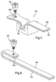
- an alternative pair of straps 20b, 24b can include a J-shaped portion.
- the strap 20b includes an open slot 30b receiving a bolt 22b.
- the strap 24b can also include an area defining an aperture (e.g., similar to element 50 depicted in Figure 3 ) that is operable to receive the bolt 22b.
- the open slot 30b and the aperture can be coaxially aligned such that both the open slot 30b and the aperture of the respective straps can simultaneously receive the bolt 22b.
- a second alternative energy absorber 16c includes straps 20c, 24c and an anvil 18c.
- the strap 20c includes an open slot 30c receiving a bolt 22c.
- Either or both strap 20c and/or strap 24c are drawable over a second anvil 52c, e.g., threadedly disposed through anvil 18c and anvil 52c.
- a portion of either or both strap 20c and/or strap 24c can be provided with a coiled portion in proximity to either or both anvil 18c and/or anvil 52c.
Landscapes
- Engineering & Computer Science (AREA)
- Mechanical Engineering (AREA)
- General Engineering & Computer Science (AREA)
- Chemical & Material Sciences (AREA)
- Combustion & Propulsion (AREA)
- Transportation (AREA)
- Steering Controls (AREA)
Claims (8)
- Ensemble formant colonne de direction (10) pour un véhicule, comprenant :une colonne de direction (12) dont la fonction est de supporter de manière ajustable un volant dans le véhicule, et mobile le long d'un trajet (14) pour un mouvement d'écrasement par rapport à un véhicule en réponse à une situation d'impact ;un absorbeur d'énergie (16, 16a, 16c) pour dissiper l'énergie associée avec ledit mouvement d'écrasement de ladite colonne de direction (12) le long dudit trajet (14), et incluant une enclume (18, 18a, 18c) disposée de manière fixe par rapport à un élément parmi ladite colonne de direction (12) et ledit trajet (14), et une première bride (20, 20a, 20b, 20c) susceptible d'être tirée par-dessus ladite enclume (18, 18a, 18c) et disposée de manière sensiblement fixe par rapport à l'autre élément parmi ladite colonne de direction (12) et ledit trajet (14) ;une seconde bride (24, 24a, 24b, 24c) disposée de manière fixe par rapport à un élément parmi ladite colonne de direction (12) et ledit trajet (14) pour dissiper l'énergie associée avec ledit mouvement d'écrasement de ladite colonne de direction (12) le long dudit trajet (14) ; etau moins un boulon à desserrage rapide (22, 22a, 22b, 22c) engagé avec ladite première bride (20, 20a, 20b, 20c) pour relâcher sélectivement ladite première bride (20, 20a, 20b, 20c) par rapport à l'autre élément parmi ladite colonne de direction (12) et ledit trajet (14), dans lequel ledit au moins un boulon à desserrage rapide (22, 22a, 22b, 22c) engage à la fois ladite première bride (20, 20a, 20b, 20c) et ladite seconde bride (24, 24a, 24b, 24c),dans lequel ladite première bride (20, 20a, 20b, 20c) inclut une fente (30, 30a, 30b, 30c), et ledit au moins un boulon à desserrage rapide (22, 22a, 22b, 22c) engage ladite fente (30, 30a, 30b, 30c),caractérisé en ce que ladite fente (30, 30a, 30b, 30c) est une fente ouverte (30, 30a, 30b, 30c).
- Ensemble formant colonne de direction (10) selon la revendication 1, dans lequel ledit au moins un boulon à desserrage rapide (22, 22a, 22b, 22c) est en outre défini comme étant un boulon incendiaire.
- Ensemble formant colonne de direction (10) selon la revendication 1, dans lequel ledit au moins un boulon à desserrage rapide (22, 22a, 22b, 22c) est en outre défini comme incluant une portion de fût (26) et une portion de tête (28) engagée de manière déplaçable avec ladite portion de fût (26).
- Ensemble formant colonne de direction (10) selon la revendication 1, comprenant en outre une seconde enclume (52c) fonctionnellement associée avec ladite enclume (18, 18a, 18c), dans lequel soit ladite première bride (20, 20a, 20b, 20c) soit ladite seconde bride (24, 24a, 24b, 24c) est disposée de manière vissée à travers ladite enclume (18, 18a, 18c) et ladite seconde enclume (52c).
- Ensemble formant colonne de direction (10) selon la revendication 1, comprenant en outre une zone définissant une ouverture (50) formée dans ladite seconde bride (24, 24a, 24b, 24c), et ledit au moins un boulon à desserrage rapide (22, 22a, 22b, 22c) est en outre défini comme engageant ladite ouverture (50).
- Ensemble formant colonne de direction (10) selon la revendication 5, dans lequel ladite fente (30, 30a, 30b, 30c) et ladite ouverture (50) sont coaxialement alignées.
- Ensemble formant colonne de direction (10) selon la revendication 1, dans lequel soit ladite première bride (20, 20a, 20b, 20c) soit ladite seconde bride (24, 24a, 24b, 24c) inclut une portion en forme de J formée en elle-même.
- Ensemble formant colonne de direction 10) selon la revendication 7, dans lequel ledit au moins un boulon à desserrage rapide (22, 22a, 22b, 22c) est en outre défini comme engageant une zone définissant une ouverture (50) formée dans ladite seconde bride (24, 24a, 24b, 24c).
Applications Claiming Priority (1)
| Application Number | Priority Date | Filing Date | Title |
|---|---|---|---|
| US68647205P | 2005-06-01 | 2005-06-01 |
Publications (3)
| Publication Number | Publication Date |
|---|---|
| EP1728703A2 EP1728703A2 (fr) | 2006-12-06 |
| EP1728703A3 EP1728703A3 (fr) | 2011-06-29 |
| EP1728703B1 true EP1728703B1 (fr) | 2012-12-12 |
Family
ID=36728506
Family Applications (1)
| Application Number | Title | Priority Date | Filing Date |
|---|---|---|---|
| EP06076093A Expired - Fee Related EP1728703B1 (fr) | 2005-06-01 | 2006-05-23 | Colonne de direction avec absorbtion adaptive d'énergie |
Country Status (2)
| Country | Link |
|---|---|
| US (1) | US7510213B2 (fr) |
| EP (1) | EP1728703B1 (fr) |
Families Citing this family (12)
| Publication number | Priority date | Publication date | Assignee | Title |
|---|---|---|---|---|
| JP4449600B2 (ja) * | 2004-06-28 | 2010-04-14 | アイシン精機株式会社 | 衝撃吸収式ステアリング装置 |
| US8033574B2 (en) * | 2006-11-15 | 2011-10-11 | Nexteer (Beijing) Technology Co., Ltd. | Collapsible steering column assembly |
| KR101065895B1 (ko) * | 2007-03-30 | 2011-09-19 | 주식회사 만도 | 충격 흡수장치를 구비한 자동차의 조향컬럼 |
| US9108673B2 (en) * | 2013-03-15 | 2015-08-18 | Steering Solutions Ip Holding Corporation | Crash release mechanism for automotive steering column |
| GB201504034D0 (en) | 2015-03-10 | 2015-04-22 | Trw Ltd | A steering column assembly |
| US10144382B2 (en) | 2015-12-15 | 2018-12-04 | Hyundai America Technical Center, Inc. | Steering column system for vehicle occupant safety |
| DE112017002484B4 (de) * | 2016-08-01 | 2021-04-22 | Robert Bosch Automotive Steering Llc | Lenksäulencrasheinrichtung mit niedrigem anfangswiderstand |
| DE102016220531A1 (de) * | 2016-10-19 | 2018-04-19 | Thyssenkrupp Ag | Lenksäule mit adaptiver Energieabsorptionsvorrichtung für ein Kraftfahrzeug |
| US10471981B2 (en) * | 2017-09-29 | 2019-11-12 | Steering Solutions Ip Holding Corporation | Buckling control assembly for a steering column energy absorption strap assembly |
| FR3079274B1 (fr) | 2018-03-26 | 2020-03-13 | Robert Bosch Automotive Steering Vendome | Dispositif d'absorption d'energie modulaire |
| KR102575152B1 (ko) * | 2018-08-07 | 2023-09-06 | 현대자동차주식회사 | 차량의 스티어링 컬럼 장치 |
| CN113682366B (zh) * | 2021-10-25 | 2022-03-01 | 坤泰车辆系统(常州)有限公司 | 具有可控吸能力的吸能器、转向管柱总成及使用方法 |
Family Cites Families (18)
| Publication number | Priority date | Publication date | Assignee | Title |
|---|---|---|---|---|
| US5605352A (en) * | 1995-12-08 | 1997-02-25 | General Motors Corporation | Energy absorbing steering column |
| US5720496A (en) * | 1996-06-17 | 1998-02-24 | General Motors Corporation | Energy absorber for motor vehicle steering column |
| SE507771C2 (sv) * | 1996-11-21 | 1998-07-13 | Volvo Ab | Anordning och förfarande för skydd av åkande i fordon |
| FR2788029B1 (fr) | 1999-01-06 | 2001-02-23 | Lemforder Nacam Sa | Dispositif d'absorption modulable d'energie d'une colonne de direction de vehicule automobile |
| DE60006815T2 (de) * | 1999-06-11 | 2004-05-27 | Delphi Technologies, Inc., Troy | Energieaufnehmer für kraftfahrzeuglenksäule |
| US6189929B1 (en) * | 1999-11-02 | 2001-02-20 | Trw Inc. | Adaptive collapsible steering column |
| US6227571B1 (en) | 1999-11-03 | 2001-05-08 | Trw Vehicle Safety Systems Inc. | Telescoping vehicle steering column apparatus for helping to protect a vehicle driver |
| FR2801269B1 (fr) * | 1999-11-19 | 2002-02-08 | Nacam | Dispositif d'absorption d'energie modulaire a charges pyrotechniques d'une colonne de direction de vehicule automobile |
| US6450532B1 (en) * | 2000-11-28 | 2002-09-17 | Delphi Technologies, Inc. | Energy absorber for motor vehicle steering column |
| US6659504B2 (en) * | 2001-05-18 | 2003-12-09 | Delphi Technologies, Inc. | Steering column for a vehicle |
| US6655716B2 (en) * | 2001-08-28 | 2003-12-02 | Delphi Technologies, Inc. | Kinetic energy absorber |
| US6749222B2 (en) * | 2001-10-19 | 2004-06-15 | Delphi Technologies, Inc. | Responsive energy absorbing device for steering columns |
| US6652002B2 (en) * | 2001-10-19 | 2003-11-25 | Delphi Technologies, Inc. | Crash responsive energy absorbing device for a steering column |
| DE60223590T2 (de) | 2001-11-30 | 2008-09-18 | Delphi Technologies, Inc., Troy | Reaktionsenergieaufnahmesystem |
| US6877775B2 (en) * | 2002-05-09 | 2005-04-12 | Delphi Technologies, Inc. | Adaptive energy absorption system |
| US6802536B2 (en) * | 2003-02-24 | 2004-10-12 | Delphi Technologies, Inc. | Adaptive energy absorbing device for a steering column |
| FR2855140B1 (fr) * | 2003-05-19 | 2006-05-26 | Nacam | Dispositif d'absorption modulable d'energie a charges pyrotechniques d'une colonne de direction de vehicule automobile |
| JP4449600B2 (ja) | 2004-06-28 | 2010-04-14 | アイシン精機株式会社 | 衝撃吸収式ステアリング装置 |
-
2006
- 2006-05-09 US US11/430,372 patent/US7510213B2/en active Active
- 2006-05-23 EP EP06076093A patent/EP1728703B1/fr not_active Expired - Fee Related
Also Published As
| Publication number | Publication date |
|---|---|
| US7510213B2 (en) | 2009-03-31 |
| EP1728703A3 (fr) | 2011-06-29 |
| EP1728703A2 (fr) | 2006-12-06 |
| US20060273569A1 (en) | 2006-12-07 |
Similar Documents
| Publication | Publication Date | Title |
|---|---|---|
| EP1728703B1 (fr) | Colonne de direction avec absorbtion adaptive d'énergie | |
| EP1728702A1 (fr) | Absorbeur d'énergie adaptif pour une colonne de direction | |
| US7661711B2 (en) | Steering column assembly with active energy absorption device | |
| US7188867B2 (en) | Pyrotechnically-controlled energy storage device for vehicle steering columns | |
| US7497470B2 (en) | Energy absorbing apparatus | |
| US7325834B2 (en) | Adaptive strap energy absorber with pin puller | |
| EP1705098B1 (fr) | Goujon de fixation rapide | |
| US7455321B2 (en) | Collapsible steering column assembly | |
| US9969345B2 (en) | Energy absorbing strap retaining device | |
| EP1083109B1 (fr) | Dispositif amortisseur pour direction | |
| US8033574B2 (en) | Collapsible steering column assembly | |
| US6749222B2 (en) | Responsive energy absorbing device for steering columns | |
| EP1839994A2 (fr) | Appareil de colonne de direction pour véhicule | |
| US8430428B2 (en) | Steering column assembly comprising a mounting capsule | |
| US6802536B2 (en) | Adaptive energy absorbing device for a steering column | |
| US20080272583A1 (en) | Steering column assembly | |
| EP1593580B1 (fr) | Absorbeur d'énergie adaptif | |
| US10807632B2 (en) | Low initial resistance steering column crash apparatus | |
| US7229096B2 (en) | Adaptive energy absorbing system using pin pullers | |
| KR101079251B1 (ko) | 차량용 스티어링 컬럼 |
Legal Events
| Date | Code | Title | Description |
|---|---|---|---|
| PUAI | Public reference made under article 153(3) epc to a published international application that has entered the european phase |
Free format text: ORIGINAL CODE: 0009012 |
|
| AK | Designated contracting states |
Kind code of ref document: A2 Designated state(s): AT BE BG CH CY CZ DE DK EE ES FI FR GB GR HU IE IS IT LI LT LU LV MC NL PL PT RO SE SI SK TR |
|
| AX | Request for extension of the european patent |
Extension state: AL BA HR MK YU |
|
| RAP1 | Party data changed (applicant data changed or rights of an application transferred) |
Owner name: GM GLOBAL TECHNOLOGY OPERATIONS, INC. |
|
| PUAL | Search report despatched |
Free format text: ORIGINAL CODE: 0009013 |
|
| AK | Designated contracting states |
Kind code of ref document: A3 Designated state(s): AT BE BG CH CY CZ DE DK EE ES FI FR GB GR HU IE IS IT LI LT LU LV MC NL PL PT RO SE SI SK TR |
|
| AX | Request for extension of the european patent |
Extension state: AL BA HR MK YU |
|
| RIC1 | Information provided on ipc code assigned before grant |
Ipc: F16F 7/12 20060101ALI20110520BHEP Ipc: B62D 1/19 20060101AFI20060809BHEP |
|
| RAP1 | Party data changed (applicant data changed or rights of an application transferred) |
Owner name: GM GLOBAL TECHNOLOGY OPERATIONS LLC |
|
| 17P | Request for examination filed |
Effective date: 20111212 |
|
| AKX | Designation fees paid |
Designated state(s): DE |
|
| GRAP | Despatch of communication of intention to grant a patent |
Free format text: ORIGINAL CODE: EPIDOSNIGR1 |
|
| GRAS | Grant fee paid |
Free format text: ORIGINAL CODE: EPIDOSNIGR3 |
|
| GRAA | (expected) grant |
Free format text: ORIGINAL CODE: 0009210 |
|
| AK | Designated contracting states |
Kind code of ref document: B1 Designated state(s): DE |
|
| RAP2 | Party data changed (patent owner data changed or rights of a patent transferred) |
Owner name: GM GLOBAL TECHNOLOGY OPERATIONS LLC Owner name: STEERING SOLUTIONS IP HOLDING CORPORATION |
|
| REG | Reference to a national code |
Ref country code: DE Ref legal event code: R096 Ref document number: 602006033557 Country of ref document: DE Effective date: 20130207 |
|
| PLBE | No opposition filed within time limit |
Free format text: ORIGINAL CODE: 0009261 |
|
| STAA | Information on the status of an ep patent application or granted ep patent |
Free format text: STATUS: NO OPPOSITION FILED WITHIN TIME LIMIT |
|
| 26N | No opposition filed |
Effective date: 20130913 |
|
| REG | Reference to a national code |
Ref country code: DE Ref legal event code: R097 Ref document number: 602006033557 Country of ref document: DE Effective date: 20130913 |
|
| PG25 | Lapsed in a contracting state [announced via postgrant information from national office to epo] |
Ref country code: DE Free format text: LAPSE BECAUSE OF NON-PAYMENT OF DUE FEES Effective date: 20131203 |
|
| REG | Reference to a national code |
Ref country code: DE Ref legal event code: R119 Ref document number: 602006033557 Country of ref document: DE Effective date: 20131203 |