EP1728589A1 - Eyeglass lens processing apparatus - Google Patents
Eyeglass lens processing apparatus Download PDFInfo
- Publication number
- EP1728589A1 EP1728589A1 EP06011281A EP06011281A EP1728589A1 EP 1728589 A1 EP1728589 A1 EP 1728589A1 EP 06011281 A EP06011281 A EP 06011281A EP 06011281 A EP06011281 A EP 06011281A EP 1728589 A1 EP1728589 A1 EP 1728589A1
- Authority
- EP
- European Patent Office
- Prior art keywords
- lens
- data
- edge position
- foreign body
- processing
- Prior art date
- Legal status (The legal status is an assumption and is not a legal conclusion. Google has not performed a legal analysis and makes no representation as to the accuracy of the status listed.)
- Granted
Links
- 238000012545 processing Methods 0.000 title claims abstract description 77
- 238000000034 method Methods 0.000 description 10
- 238000001514 detection method Methods 0.000 description 5
- 230000003287 optical effect Effects 0.000 description 5
- 239000002390 adhesive tape Substances 0.000 description 4
- 230000002950 deficient Effects 0.000 description 4
- 239000000853 adhesive Substances 0.000 description 3
- 230000001070 adhesive effect Effects 0.000 description 3
- 238000013459 approach Methods 0.000 description 3
- 230000002093 peripheral effect Effects 0.000 description 3
- 239000011248 coating agent Substances 0.000 description 2
- 238000000576 coating method Methods 0.000 description 2
- 238000004891 communication Methods 0.000 description 2
- 238000010586 diagram Methods 0.000 description 2
- 230000004069 differentiation Effects 0.000 description 2
- 238000005259 measurement Methods 0.000 description 2
- 239000004033 plastic Substances 0.000 description 2
- 229920003023 plastic Polymers 0.000 description 2
- 238000012935 Averaging Methods 0.000 description 1
- 230000000903 blocking effect Effects 0.000 description 1
- 230000000994 depressogenic effect Effects 0.000 description 1
- 239000000284 extract Substances 0.000 description 1
- 239000011521 glass Substances 0.000 description 1
- 239000000463 material Substances 0.000 description 1
- 239000005871 repellent Substances 0.000 description 1
- 239000004575 stone Substances 0.000 description 1
- 239000002699 waste material Substances 0.000 description 1
- XLYOFNOQVPJJNP-UHFFFAOYSA-N water Substances O XLYOFNOQVPJJNP-UHFFFAOYSA-N 0.000 description 1
Images



Classifications
-
- B—PERFORMING OPERATIONS; TRANSPORTING
- B24—GRINDING; POLISHING
- B24B—MACHINES, DEVICES, OR PROCESSES FOR GRINDING OR POLISHING; DRESSING OR CONDITIONING OF ABRADING SURFACES; FEEDING OF GRINDING, POLISHING, OR LAPPING AGENTS
- B24B49/00—Measuring or gauging equipment for controlling the feed movement of the grinding tool or work; Arrangements of indicating or measuring equipment, e.g. for indicating the start of the grinding operation
-
- B—PERFORMING OPERATIONS; TRANSPORTING
- B24—GRINDING; POLISHING
- B24B—MACHINES, DEVICES, OR PROCESSES FOR GRINDING OR POLISHING; DRESSING OR CONDITIONING OF ABRADING SURFACES; FEEDING OF GRINDING, POLISHING, OR LAPPING AGENTS
- B24B9/00—Machines or devices designed for grinding edges or bevels on work or for removing burrs; Accessories therefor
- B24B9/02—Machines or devices designed for grinding edges or bevels on work or for removing burrs; Accessories therefor characterised by a special design with respect to properties of materials specific to articles to be ground
- B24B9/06—Machines or devices designed for grinding edges or bevels on work or for removing burrs; Accessories therefor characterised by a special design with respect to properties of materials specific to articles to be ground of non-metallic inorganic material, e.g. stone, ceramics, porcelain
- B24B9/08—Machines or devices designed for grinding edges or bevels on work or for removing burrs; Accessories therefor characterised by a special design with respect to properties of materials specific to articles to be ground of non-metallic inorganic material, e.g. stone, ceramics, porcelain of glass
- B24B9/14—Machines or devices designed for grinding edges or bevels on work or for removing burrs; Accessories therefor characterised by a special design with respect to properties of materials specific to articles to be ground of non-metallic inorganic material, e.g. stone, ceramics, porcelain of glass of optical work, e.g. lenses, prisms
- B24B9/148—Machines or devices designed for grinding edges or bevels on work or for removing burrs; Accessories therefor characterised by a special design with respect to properties of materials specific to articles to be ground of non-metallic inorganic material, e.g. stone, ceramics, porcelain of glass of optical work, e.g. lenses, prisms electrically, e.g. numerically, controlled
Definitions
- the present invention relates to an eyeglass lens processing apparatus for processing an eyeglass lens.
- an eyeglass lens is held (chucked) by two lens chuck shafts and is rotated, while the peripheral edge of the lens is processed by a processing tool such as a grindstone so that the lens can have a shape substantially identical with a target lens shape (traced outline).
- a cup serving as a fixing jig is mounted on and fixed to a front refractive surface of 'the' lens through a double-sided adhesive tape, the cup with the lens fixed thereto is mounted on a cup receiver at a distal end of one of the two lens chuck shafts, and a lens holder at a distal end of the other lens chuck shaft is brought into contact with a rear refractive surface of the lens.
- a film-shaped adhesive sheet may be bonded onto the refractive surface of the lens and, after then, the cup is mounted on and fixed to the lens through a double-sided adhesive tape.
- the shape of the lens is measured (the edge position of the lens is detected) in accordance with the target lens shape.
- the adhesive tape is bonded in such a manner that it is sticking out of the cup greatly, or when the adhesive sheet is bonded while creased, there is a possibility that an error can be included in the measuring result.
- defective processing can occur. Such defective processing can also occur similarly when some other foreign bodies stick to the refractive surface of the lens.
- the technical object of the present invention is to provide an eyeglass lens processing apparatus which can detect whether foreign bodies exist on a refractive surface of an eyeglass lens or not, thereby being able to prevent the defective processing of the lens previously.
- the present invention is characterized by having the following arrangements.
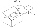
- Fig. 1 is a schematic external view of an eyeglass lens processing apparatus 1 according to the embodiment of the invention.
- An eyeglass frame measuring apparatus 2 is connected to the processing apparatus 1.
- the measuring apparatus 2 there can be used a measuring apparatus which is disclosed in, for example, US 5333412 ( Japanese patent publication Hei-4-93164 ) and US Re.35898 ( Japanese patent publication Hei-5-212661 ).
- a touch panel 410 serving not only as a display portion for processing information and the like but also as an input portion for inputting processing conditions and the like, and a switch portion 420 including switches for instruction of processing such as a processing start switch are mounted on the top portion of the processing apparatus 1.
- a lens to be processed is processed in a processing chamber which is formed within an opening/closing window 402.
- the processing apparatus 1 may be formed integrally with the measuring apparatus 2.
- Fig. 2 is a schematic structure view of a lens processing portion disposed within the box body of the processing apparatus 1.
- a carriage portion 700 which includes a carriage 701 and its moving mechanism is mounted on a main base 10.
- a lens LE to be processed is held (chucked) by two lens chuck shafts 702L and 702R respectively rotatably held on the carriage 701, is rotated, and is ground or processed by a grindstone 602.
- the grindstone 602 according to the present embodiment includes a rough processing grindstone 602a for glass, a rough processing grindstone 602b for plastics, and a processing grindstone 602c for bevel-finishing and flat-finishing.
- a grindstone rotating shaft 601a, on which the grindstone 602 is mounted, is connected to a grindstone rotating motor 601.
- the chuck shafts 702L and 702R are held on the carriage 701 in such a manner that their axes (the axis of rotation of the lens LE) are parallel to an axis of the shaft 601a (the axis of rotation of the grindstone 602).
- the carriage 701 can be moved not only in a direction of the axis of the shaft 601a (a direction of the axes of the chuck shafts 702L and 702R) (in the X-axis direction) but also in a direction perpendicular to the X-axis direction (in a direction where the distance between the axes of the chuck shafts 702L and 702R and the axis of the shaft 601a is varied) (in the Y-axis direction).
- the chuck shaft 702L is held on a left arm 701L of the carriage 701 and the chuck shaft 702R is held on a right arm 701R thereof in such a manner that they can be rotated and are coaxial with each other.
- a cup receiver 730 is mounted on the distal end of the chuck shaft 702L.
- a lens holder 731 is mounted on the distal end of the chuck shaft 702R (see Fig. 3).
- a lens holding (chucking) motor 710 is fixed to the right arm 701R.
- the rotational movement of the motor 710 is transmitted through a pulley 711 mounted on the rotation shaft of the motor 710, a belt 712 and a pulley 713 to a feed screw (not shown) connected to the pulley 713; the rotational movement of the feed screw moves a feed nut (not shown) in the axial direction thereof, the feed nut being threadedly engaged with the feed screw; and, the movement of the feed nut moves the chuck shaft 702R in the axial direction thereof, the chuck shaft 702R being connected with the feed nut.
- the chuck shaft 702R is moved in a direction to approach the chuck shaft 702L, so that the lens LE can be held (chucked) by the chuck shafts 702L and 702R.
- a lens rotating motor 720 fixed to the left arm 701L The rotational movement of the motor 720 is transmitted through a gear 721 mounted on the rotation shaft of the motor 720, a gear 722, a gear 723 coaxial with the gear 722, a gear 724, and a gear 725 mounted on the chuck shaft 702L to the chuck shaft 702L, so that the chuck shaft 702L can be rotated. Further, the rotational movement of the motor 720 is transmitted to the chuck shaft 702 through a rotary shaft 728 connected to the rotation shaft of the motor 720 and gears respectively similar to the gears 721 - 725, thereby rotating the chuck shaft 702R. As a result of this, the chuck shafts 702L and 702R are rotated synchronously with each other, thereby rotating the lens LE which is held (chucked) by them.
- a moving support base 740 is movably supported by two guide shafts 703 and 704 which are fixed on the base 10 to be parallel thereto and extend in the X-axis direction. Further, an X-axis direction moving motor 745 is fixed on the base 10. The rotational movement of the motor 745 is transmitted to the support base 740 through a pinion gear (not shown) mounted on the rotation shaft of the motor 745 and a rack gear (not shown) mounted on the rear portion of the support base 740, so that the support base 740 can be moved in the X-axis direction. As a result of this, the carriage 701 supported by two guide shafts 756 and 757 respectively fixed to the support base 740 can be moved in the X-axis direction.
- the carriage 701 is movably supported by the guide shafts 756 and 757 which are fixed to the support base 740 to be parallel thereto and extend in the Y-axis direction. Further, a Y-axis direction moving motor 750 through a plate 751 is fixed to the support base 740. The rotational movement of the motor 750 is transmitted through a pulley 752 mounted on the rotation shaft of the motor 750 and a belt 753 to a feed screw 755 which is rotatably held on the plate 751; and, owing to the rotational movement of the feed screw 755, the carriage 701 with which the feed screw 755 is threadedly engaged is moved in the Y-axis direction. Lens shape measuring portions 500F and 500R are disposed above the carriage 701. A chamfering/grooving portion 800 is arranged in front of the carriage 701.
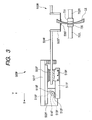
- Fig. 3 is a schematic structure view of the lens shape measuring portion 500F for measuring the shape of the front refractive surface of the lens LE.
- a fixed support base 501F is' fixed mounted on a sub-base 100 standing on the main base 10 (see Fig. 2) ; and a slider 503F is movably supported by a guide rail 502F fixed to the support base 501F and extending in the X-axis direction.
- a moving support base 510F is fixed to the slider 503F; and, a feeler arm 504F is fixed to the support base 510F.
- An L-shaped feeler hand 505F is fixed to the distal end of the arm 504F; and a disk-shaped feeler 506F is fixed to the distal end of the hand 505F.
- the feeler 506F is brought into contact with the front refractive surface of the lens LE.
- a rack gear 511F is fixed to the lower portion of the support base 510F; and a pinion gear 512F which is mounted on the rotation shaft of an encoder 513F fixed to the support base 501F is engaged with the gear 511F. Further, a motor 516F is fixed to the support base 501F. The rotational movement of the motor 516F is transmitted to the gear 511F through a gear 515F mounted on the rotation shaft of the motor 516F, a gear 514F, and the gear 512F, so that the gear 511F, support base 510F, arm 504F and the like are moved in the X-axis direction.
- the motor 516F is always pressing the feeler 506F against the front refractive surface of the lens LE with a constant force.
- the encoder 513F detects the moving amount of the support base 510F or the like in the X-axial direction (the position of the feeler 506F). In accordance with the thus detected moving amount (position) and the rotation angles of the chuck shafts 702L and 702R, the shape of the front refractive surface of the lens LE is measured.
- the lens shape measuring portion 500R for measuring the shape of the rear refractive surface of the lens LE is symmetrical to the lens shape measuring portion 500F and, therefore, the description thereof is omitted here.
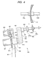
- Fig. 4 is a schematic structure view of the chamfering and grooving portion 800.
- a fixed support base 801 which serves as the base of the chamfering and grooving portion 800, is fixed to the upper surface of the base 10 (see Fig. 2) and, a plate 802 is fixed to the support base 801.
- a hold member 811 which rotatably holds an arm rotating member 810 is fixed to the plate 802.
- a gear 813 is fixed to the rotating member 810 which extends leftward of the plate 802. The rotational movement of the motor 805 is transmitted through a gear 807 mounted on the rotation shaft of the motor 805, a gear 815 and the gear 813 to the rotating member 810, so that the arm 820 fixed to the rotating member 810 can be rotated.
- a grindstone rotating motor 821 is fixed to the gear 813.
- the rotational movement of the motor 821 is transmitted to a grindstone rotating shaft 830 through a rotary shaft 823 connected to the rotation shaft of the motor 821 and rotatably held by the rotating member 810, a pulley 824 mounted on the shaft 823, a belt 835, and a pulley 832 mounted on the shaft 830 rotatably held by a hold member 831 which is fixed to the arm 820, so that the shaft 830 can be rotated.
- a processing grindstone 841a for chamfering the rear surface of the lens LE, a processing grindstone 841b for chambering the front surface of the lens LE and a processing grinding stone 842 for grooving which are respectively mounted on the shaft 830 can be rotated.
- the axis of the shaft 830 is set inclined about 8° with respect to the axes of the chuck shafts 702L and 702R, which makes it easy for the grindstone portion 840 to follow the curve of the lens LE.
- the chamfering grindstones 841a, 841b and grooving grindstone 842 are respectively set about 30 mm in outer diameter.
- the arm 820 is rotated by the motor 805, while the grindstone portion 840 is moved to its retreating position or processing position.
- the processing position of the grindstone portion 840 is a position which exists between the chuck shafts 702L, 702R and the shaft 601a and where the rotation axis of the shaft 830 is set on a plane on which the rotation axes of the two kinds of shafts are present. Owing to this, similarly to the peripheral edge processing operation by the grindstone 602, the axis-to-axis distance between the rotation axes of the chuck shafts 702L, 702R and the rotation axis of the shaft 830 can be varied by the motor 751.
- the shapes of right and left rims of an eyeglass frame are measured using the measuring apparatus 2, thereby obtaining target lens shape data thereof.
- the shape of a template or the shape of a dummy lens is measured, thereby obtaining target lens shape data thereof.
- the target lens shape data may be input from an external computer or the like through communication means (not shown), or may be input through a bar code reader or the like.
- a target lens shape figure is displayed on the screen of the touch panel 410 based on the target lens shape data.
- An operator may operate a touch key displayed on the touch panel 410 to input lay-out data such as FPD (distance between the geometric centers of the right and left rims), PD of a eyeglass wearer (distance between pupils-centers of the eyeglass wearer), the height of an optical center of the lens LE with respect to the geometric center OF of the target lens shape, and the like. Further, the operator may operate a touch key displayed on the touch panel 410 to thereby set (input) the material of the lens LE, the kind of the eyeglass frame, the processing mode, whether a chamfering operation is necessary or not, and the like. When these processing conditions are set once, according to a program stored in a memory 163 in advance, a processing procedure and the like are decided by a main control portion 160.
- FPD distance between the geometric centers of the right and left rims
- PD of a eyeglass wearer distance between pupils-centers of the eyeglass wearer
- a cup 50 is mounted on and fixed to the front refractive surface of the lens LE using a blocking device.
- the cup 50 is mounted on and fixed to the lens LE through a double-sided adhesive tape 51.
- a film-shaped adhesive sheet 52 may be firstly bonded to the front refractive surface of the lens and, after then, the cup 50 may be mounted on and fixed to the lens through the tape 51.
- the sheet 52 may also be bonded to the rear refractive surface of the lens.
- the base portion of the cup 50 is mounted on the cup receiver 730. Then, when the lens holding (chucking) switch of the switch portion 420 is pressed down, the chuck shaft 702R is moved in the direction to approach the chuck shaft 702L, the lens holder 731 is contacted with the rear refractive surface of the lens LE, and the lens LE is held (chucked) by the chuck shafts 702L and 702R.
- the main control portion 160 controls the lens shape measuring portions 500F and 500R in accordance with the target lens shape data input therein, thereby measuring the shape of the lens LE (detecting the edge position thereof).
- the target lens shape data stored in the memory 161 with the geometric center OF of the target lens shape as a reference are converted to the target lens shape data with the optical center thereof as a reference in accordance with the layout data such as the input FPD, PD and optical center height, and are used.
- the target lens shape data with the geometric center OF of the target lens shape as a reference stored in the memory 161 can be used as they are. Now, description will be given below of the boxing center holding mode.
- the main control portion 160 drive the motor 516 F to move the arm 504F from its retreating position to its measuring position and, after then, in accordance with the target lens shape data, drives the motor 750 to move the carriage 701 and drives the motor 516F to move the arm 504F toward the lens LE (in a direction to approach the lens LE), thereby bringing the feeler 506F into contact with the front refractive surface of the lens LE. Then, in a state where the feeler 506F is in contact with the front refractive surface, the main control portion 160 drives the motor 750 in accordance with the target lens shape data, while driving the motor 720 to rotate the lens LE, to thereby move up and down the carriage 701.
- the feeler 506F is moved in the axial direction of the chuck shafts 702L and 702R (in the X-axis direction) along the shape of the front refractive surface of the lens LE.
- zfn expresses the height (thickness) of the front refractive surface of the lens LE.
- zrn expresses the height (thickness) of the rear refractive surface of the lens LE.
- the data of the shapes of the front and rear refractive surfaces of the lens LE are stored in the memory 161.
- the main control portion 160 detects whether a foreign body is present or not on the refractive surface of the lens LE in accordance with the measured (detected) results of the lens shape (edge position).
- the foreign body on the refractive surface of the lens LE includes, for example, the tape 51 bonded in such a manner that it sticks greatly out of the cup 50 which often occurs when the lens LE is processed so as to substantially coincide with a target lens shape which has a narrow top-and-bottom width (vertical width), the sheet 52 bonded in a creased manner, or a processing waste remaining within the processing chamber.
- Fig. 9A is a graphical representation of the target lens shape data shown in Fig. 7, in which the horizontal axis expresses the radial angle ⁇ and the vertical axis expresses the radial length SR.
- Fig. 9B is a graphical representation of the measured (detected) results of the front refractive surface shape (edge position) of the lens LE, in which the horizontal axis expresses the radial angle ⁇ and the vertical axis expresses the edge position zf from the reference position (distance from the reference position to the edge).
- the main control portion 160 differentiates the edge position data shown in Fig. 9B.
- Fig. 10 shows the results of the differentiation of the edge position data.
- the main control portion 160 extracts points (radial angles) having a large varying amount from the differentiated data.
- the reason for this is that, if there is present any foreign body such as the tape 51 on the refractive surface of the lens LE, normally, a sharp variation occurs in the edge position data.
- portions ⁇ F ⁇ a, ⁇ F ⁇ b, ⁇ F ⁇ c, and ⁇ F ⁇ d which respectively exceed a given threshold value ( ⁇ 20) are extracted.
- variations in the edge position data may be compared with variations in the target lens shape data with respect to the same radial angle; and, in accordance with their mutual correlation, presence or absence of the foreign body is detected.
- the lens refractive surface has a curve
- the peak of the variation of the edge position data substantially coincides with the peak of the variation of the target lens shape data (the inflection point of the radial length data).
- the peak of the variation of the edge position data appears even in a point where the peak of the variation of the target lens shape data is not found.
- the peak of the variation of the edge position data can be extracted from the differentiated data.
- the peak of the variation of the edge position data shown in Fig. 9B can be retrieved based on the waveform of the differentiated data shown in Fig. 10.
- the portion ⁇ F ⁇ a is firstly extracted as a point having a large variation amount of the differentiated data. Since this portion ⁇ F ⁇ a is a portion which has a large minus value in the differentiated data, by retrieving the increasing side of the edge position data existing leftward of this portion, a point FPa in Fig. 9B is extracted as the peak of the variation of the edge position data.
- the portion ⁇ F ⁇ b extracted as a point having a large variation amount in the differentiated data is a portion having a large plus value in the differentiated data
- a point FPb in Fig. 9B is extracted as the peak of the variation of the edge position data.
- a point FPc in Fig. 9B is extracted as the peak of the variation of the edge position data.
- the main control portion 160 displays an error message or the like on the touch panel 410 and limits (stops) the processing operations to be executed thereafter.
- the operator must take out the lens LE from the chuck shafts 702L and 702R once, remove the foreign body existing on the refractive surfaces of the lens LE (and bond the tape 51 and sheet 52 again), make the chuck shafts 702L and 702R hold (chuck) the lens LE again, and resume the processing operation.
- the processing apparatus is structured such that the existing position of the foreign body can be displayed on the touch panel 410, it is easier for the operator to check the presence or absence of the foreign body.
- the main control portion 160 executes the peripheral edge processing operation of the lens LE.
- the lens LE is a plastic lens
- the main control portion 160 drives the motor 745 to move the carriage 701 in the X-axis direction and thereby set the lens LE on the grindstone 602b; and the main control portion 160 drives the motor 720 to rotate the lens LE and simultaneously drives the motor 750 to move the carriage 701 up and down based on the rough processing data obtained from the target lens shape data, thereby executing a rough processing operation on the lens LE.
- a finishing (finish operation) operation is started.
- the main control portion 160 finds bevel-finishing data in accordance with the edge position data on the front and rear surfaces of the lens LE. And, the main control portion 160 drives the motor 745 to move the carriage 701 in the X-axis direction and thereby set the lens LE on a beveling groove formed in the grindstone 602c. Then, in accordance with the bevel-finishing data, the main control portion 160 drives the motor 720 to rotate the lens LE and simultaneously drives the motors 745 and 750 to move the carriage 701 right and left as well as up and down, thereby carrying out a bevel-finishing operation.
- the main control portion 160 finds flat finishing data and grooving data in accordance with the target lens shape data and the edge position data on the front and rear surfaces of the lens LE. Then, the main control portion 160 drives the motor 745 to move the carriage 701 in the X-axis direction and thereby sets the lens LE on a flat portion of the grindstone 602c. Then, in accordance with the flat-finishing data, the main control portion 160 drives the motor 720 to rotate the lens LE and simultaneously drives the motors 745 and 750 to move the carriage 701 right and left as well as up and down, thereby executing a flat-finishing operation on the lens LE.
- the main control portion 160 drives the motor 745 to move the carriage 701 in the X-axis direction and thereby sets the lens LE on the grindstone 842 moved to its processing position; and the main control portion 160 drives the motor 720 to rotate the lens LE and simultaneously drives the motors 745 and 750 to move the carriage 701 right and left as well as up and down in accordance with the grooving data, thereby carrying out a grooving operation on the lens LE.
- the main control portion 160 in the above-mentioned lens shape measuring operation, detects the edge position of the lens LE in accordance with the target lens shape data and, after then, detects the edge position existing 0.5 mm inwardly or outwardly of the radial length of the target lens shape data.
- This two edge position detecting operations are performed respectively on the front and rear surfaces of the lens LE and, based on the results of such detecting operations, the respective inclined conditions of the front and rear surfaces are obtained.
- the main control portion 160 finds chamfering data on the front and rear surfaces of the lens LE.
- the main control portion 160 drives the motor 745 to move the carriage 701 in the X-axis direction and thereby sets the lens LE oh the grindstone 841a moved to its processing position; and the main control portion 160 drives the motor 720 to rotate the lens LE and simultaneously drives the motors 745 and 750 to move the carriage 701 right and left as well as up and down in accordance with the chamfering data on the lens rear surface, thereby executing a chamfering operation on the lens rear surface.
- the main control portion 160 drives the motor 745 to move the carriage 701 in the X-axis direction and thereby sets the lens LE on the grindstone 841b; and the main control portion 160 drives the motor 720 to rotate the lens LE and simultaneously drives the motors 745 and 750 to move the carriage 701 right and left as well as up and down based on the chamfering data on the lens front surface, thereby carrying out a chamfering operation on the lens front surface.
- the above-mentioned foreign body detecting method can be changed in other various manners.
- a foreign body detecting method based on the mutual correlation between the variations of the edge position data and the variations of the target lens shape data there can also be employed the following method.
- Fig. 11 shows the results of differentiation of the target lens shape data shown in Fig. 9A.
- the differentiated data of the target lens shape data is compared with the differentiated data of the edge position data shown in Fig. 10.
- the portions ⁇ F ⁇ a, ⁇ F ⁇ b, ⁇ F ⁇ c, and ⁇ F ⁇ d which are respectively extracted as points having a large variation amount in Fig.
- ⁇ SR ⁇ a which is the peak of the variation in Fig. 11 exists in the vicinity of the radial angle of ⁇ F ⁇ a which is the peak of the variation shown in Fig. 10
- ⁇ SR ⁇ b which is the peak of the variation in Fig. 11 is exists in the vicinity of the radial angle of ⁇ F ⁇ b which is the peak of the variation shown in Fig. 10.
- no peak of the variation in Fig. 11 exists in the vicinity of the respective radial angles of the portions ⁇ F ⁇ c and ⁇ F ⁇ d which are respectively the peaks of the variation in Fig.
- the foreign body detection can also be realized in such a manner that, by using the differentiated results of the edge position data and target lens shape data, it is checked whether the sharply varying points of the target lens shape data is present or not in the vicinity of the sharply varying points of the edge position data.
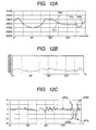
- Fig. 12A is a graphical representation of the results of edge position detection made twice on the front surface of the lens LE.
- FL0 similarly in Fig. 9A, expresses measurement results obtained in a first measuring path of the target lens shape data
- FL1 expresses measurement results obtained in the second measuring path existing 0.5 mm inwardly of the first measuring path.
- Fig. 12B is a graphical representation of the difference data between FL0 and FL1.
- Fig. 12C is a graphical representation of results obtained by differentiating the difference data. Incidentally, in the differentiating process in Fig. 12C, in order to facilitate the understanding of a sharply varying tendency, the detection results of the edge positions in 1000 points are calculated by averaging them by 10 points.
- Fig. 12A there is shown an example of the lens front surface in which a foreign body is present between two points FPc and FPd on FL0.
- Fig. 12C it is checked whether there exists or not a point varying sharply exceeding a given threshold value; and, the presence or absence of a foreign body is detected depending on the presence or absence of such point.
- the threshold value which is used to detect the presence or absence of the foreign body, may be determined experimentally.
- the presence or absence of a foreign body on the refractive surface of a lens can be detected before the lens is processed, thereby being able to prevent the defective processing of the lens.
Landscapes
- Engineering & Computer Science (AREA)
- Mechanical Engineering (AREA)
- Chemical & Material Sciences (AREA)
- Ceramic Engineering (AREA)
- Inorganic Chemistry (AREA)
- Grinding And Polishing Of Tertiary Curved Surfaces And Surfaces With Complex Shapes (AREA)
Abstract
Description
- The present invention relates to an eyeglass lens processing apparatus for processing an eyeglass lens.
- In an eyeglass lens processing apparatus, an eyeglass lens is held (chucked) by two lens chuck shafts and is rotated, while the peripheral edge of the lens is processed by a processing tool such as a grindstone so that the lens can have a shape substantially identical with a target lens shape (traced outline). To hold the lens, a cup serving as a fixing jig is mounted on and fixed to a front refractive surface of 'the' lens through a double-sided adhesive tape, the cup with the lens fixed thereto is mounted on a cup receiver at a distal end of one of the two lens chuck shafts, and a lens holder at a distal end of the other lens chuck shaft is brought into contact with a rear refractive surface of the lens. Further, to hold a lens having a refractive surface easy to slip such as a lens on which a water repellant coating is enforced, a film-shaped adhesive sheet may be bonded onto the refractive surface of the lens and, after then, the cup is mounted on and fixed to the lens through a double-sided adhesive tape.
- When processing the lens, the shape of the lens is measured (the edge position of the lens is detected) in accordance with the target lens shape. In this case, when the adhesive tape is bonded in such a manner that it is sticking out of the cup greatly, or when the adhesive sheet is bonded while creased, there is a possibility that an error can be included in the measuring result. And, when the lens is processed based on the processing data that have been obtained from the measuring results containing such error, defective processing can occur. Such defective processing can also occur similarly when some other foreign bodies stick to the refractive surface of the lens.
- The technical object of the present invention is to provide an eyeglass lens processing apparatus which can detect whether foreign bodies exist on a refractive surface of an eyeglass lens or not, thereby being able to prevent the defective processing of the lens previously.
- In order to achieve the above object, the present invention is characterized by having the following arrangements.
- (1) An eyeglass lens processing apparatus, comprising;
- lens holding means for holding an eyeglass lens;
- data input means for inputting target lens shape data;
- lens measuring means for measuring a refractive surface of the held lens based on the target lens shape data to obtain an edge position of the lens; and
- foreign body detecting means for detecting presence or absence of a foreign body on the lens refractive surface based on the obtained edge position data.
- (2) The eyeglass lens processing apparatus according to (1), wherein the foreign body detecting means detects the presence or absence of the foreign body based on a mutual correlation between a variation of the edge position data and a variation of the target lens shape data.
- (3) The eyeglass lens processing apparatus according to (2), wherein the foreign body detecting means detects the presence or absence of the foreign body based on whether an inflection point of the target lens shape data is present or not in the vicinity of an inflection point of the edge position data, or on whether a sharply varying point of the target lens shape data is present or not in the vicinity of a sharply varying point of the edge position data.
- (4) The eyeglass lens processing apparatus according to (1), wherein
the lens measuring means measures the lens refractive surface in a first measuring path based on the target lens shape data and a second measuring path arranged a given distance inwardly or outwardly of the first measuring path to obtain the edge position data, and
the foreign body detecting means detects the presence or absence of the foreign body based on a difference between the edge position data in the first measuring path and the edge position data in the second measuring path. - (5) An eyeglass lens processing apparatus according to (1) further comprising:
- lens processing means for processing the held lens; and
- processing controlling means for limiting the processing of the lens when the presence of the foreign body is detected.
-
- Fig. 1 is a schematic external view of an eyeglass lens processing apparatus according to an embodiment of the invention.
- Fig. 2 is a schematic structure view of a lens processing portion of the eyeglass lens processing apparatus.
- Fig. 3 is a schematic structure view of a lens shape measuring portion of the eyeglass lens processing apparatus.
- Fig. 4 is a schematic structure view of a chamfering/grooving portion of the eyeglass lens processing apparatus.
- Fig. 5 is a schematic block diagram of a control system of the eyeglass lens processing apparatus.
- Figs. 6A and 6B are explanatory views to show how to fix a cup to the refractive surface of a lens.
- Fig. 7 is an explanatory view of target lens shape data.
- Fig. 8 is a flow chart to show how to detect whether a foreign body is present on the refractive surface of the lens or not.
- Figs. 9A and 9B are views to show the target lens shape data and the edge position data of the front surface of the lens.
- Fig. 10 is a view of differentiated data of the edge position data.
- Fig. 11 is a view of differentiated data of the target lens shape data.
- Figs. 12A to 12C are explanatory views of a method for detecting a foreign body from a difference between two edge positions data.
- Now, an embodiment according to the invention will be described with reference to the accompanying drawings. Fig. 1 is a schematic external view of an eyeglass
lens processing apparatus 1 according to the embodiment of the invention. An eyeglassframe measuring apparatus 2 is connected to theprocessing apparatus 1. As themeasuring apparatus 2, there can be used a measuring apparatus which is disclosed in, for example,US 5333412 (Japanese patent publication Hei-4-93164 US Re.35898 (Japanese patent publication Hei-5-212661 touch panel 410 serving not only as a display portion for processing information and the like but also as an input portion for inputting processing conditions and the like, and aswitch portion 420 including switches for instruction of processing such as a processing start switch are mounted on the top portion of theprocessing apparatus 1. A lens to be processed is processed in a processing chamber which is formed within an opening/closing window 402. Incidentally, theprocessing apparatus 1 may be formed integrally with themeasuring apparatus 2. - Fig. 2 is a schematic structure view of a lens processing portion disposed within the box body of the
processing apparatus 1. Acarriage portion 700 which includes acarriage 701 and its moving mechanism is mounted on amain base 10. A lens LE to be processed is held (chucked) by twolens chuck shafts carriage 701, is rotated, and is ground or processed by agrindstone 602. Thegrindstone 602 according to the present embodiment includes arough processing grindstone 602a for glass, arough processing grindstone 602b for plastics, and aprocessing grindstone 602c for bevel-finishing and flat-finishing. Agrindstone rotating shaft 601a, on which thegrindstone 602 is mounted, is connected to agrindstone rotating motor 601. - The
chuck shafts carriage 701 in such a manner that their axes (the axis of rotation of the lens LE) are parallel to an axis of theshaft 601a (the axis of rotation of the grindstone 602). Thecarriage 701 can be moved not only in a direction of the axis of theshaft 601a (a direction of the axes of thechuck shafts chuck shafts shaft 601a is varied) (in the Y-axis direction). - The
chuck shaft 702L is held on aleft arm 701L of thecarriage 701 and thechuck shaft 702R is held on aright arm 701R thereof in such a manner that they can be rotated and are coaxial with each other. Acup receiver 730 is mounted on the distal end of thechuck shaft 702L. Alens holder 731 is mounted on the distal end of thechuck shaft 702R (see Fig. 3). A lens holding (chucking)motor 710 is fixed to theright arm 701R. The rotational movement of themotor 710 is transmitted through apulley 711 mounted on the rotation shaft of themotor 710, abelt 712 and apulley 713 to a feed screw (not shown) connected to thepulley 713; the rotational movement of the feed screw moves a feed nut (not shown) in the axial direction thereof, the feed nut being threadedly engaged with the feed screw; and, the movement of the feed nut moves thechuck shaft 702R in the axial direction thereof, thechuck shaft 702R being connected with the feed nut. As a result of this, thechuck shaft 702R is moved in a direction to approach thechuck shaft 702L, so that the lens LE can be held (chucked) by thechuck shafts - A
lens rotating motor 720 fixed to theleft arm 701L. The rotational movement of themotor 720 is transmitted through agear 721 mounted on the rotation shaft of themotor 720, agear 722, agear 723 coaxial with thegear 722, agear 724, and agear 725 mounted on thechuck shaft 702L to thechuck shaft 702L, so that thechuck shaft 702L can be rotated. Further, the rotational movement of themotor 720 is transmitted to the chuck shaft 702 through arotary shaft 728 connected to the rotation shaft of themotor 720 and gears respectively similar to the gears 721 - 725, thereby rotating thechuck shaft 702R. As a result of this, thechuck shafts - A moving support base 740 is movably supported by two
guide shafts direction moving motor 745 is fixed on thebase 10. The rotational movement of themotor 745 is transmitted to the support base 740 through a pinion gear (not shown) mounted on the rotation shaft of themotor 745 and a rack gear (not shown) mounted on the rear portion of the support base 740, so that the support base 740 can be moved in the X-axis direction. As a result of this, thecarriage 701 supported by twoguide shafts - The
carriage 701 is movably supported by theguide shafts direction moving motor 750 through a plate 751 is fixed to the support base 740. The rotational movement of themotor 750 is transmitted through apulley 752 mounted on the rotation shaft of themotor 750 and abelt 753 to afeed screw 755 which is rotatably held on the plate 751; and, owing to the rotational movement of thefeed screw 755, thecarriage 701 with which thefeed screw 755 is threadedly engaged is moved in the Y-axis direction.
Lensshape measuring portions carriage 701. A chamfering/grooving portion 800 is arranged in front of thecarriage 701. - Now, Fig. 3 is a schematic structure view of the lens
shape measuring portion 500F for measuring the shape of the front refractive surface of the lens LE. A fixedsupport base 501F is' fixed mounted on a sub-base 100 standing on the main base 10 (see Fig. 2) ; and aslider 503F is movably supported by aguide rail 502F fixed to thesupport base 501F and extending in the X-axis direction. A movingsupport base 510F is fixed to theslider 503F; and, afeeler arm 504F is fixed to thesupport base 510F. An L-shapedfeeler hand 505F is fixed to the distal end of thearm 504F; and a disk-shapedfeeler 506F is fixed to the distal end of thehand 505F. When measuring the shape of the front refractive surface of the lens LE, thefeeler 506F is brought into contact with the front refractive surface of the lens LE. - A
rack gear 511F is fixed to the lower portion of thesupport base 510F; and apinion gear 512F which is mounted on the rotation shaft of anencoder 513F fixed to thesupport base 501F is engaged with thegear 511F. Further, amotor 516F is fixed to thesupport base 501F. The rotational movement of themotor 516F is transmitted to thegear 511F through agear 515F mounted on the rotation shaft of themotor 516F, agear 514F, and thegear 512F, so that thegear 511F,support base 510F,arm 504F and the like are moved in the X-axis direction. During the measuring operation, themotor 516F is always pressing thefeeler 506F against the front refractive surface of the lens LE with a constant force. Theencoder 513F detects the moving amount of thesupport base 510F or the like in the X-axial direction (the position of thefeeler 506F). In accordance with the thus detected moving amount (position) and the rotation angles of thechuck shafts - Incidentally, the lens
shape measuring portion 500R for measuring the shape of the rear refractive surface of the lens LE is symmetrical to the lensshape measuring portion 500F and, therefore, the description thereof is omitted here. - Now, Fig. 4 is a schematic structure view of the chamfering and grooving
portion 800. A fixedsupport base 801, which serves as the base of the chamfering and groovingportion 800, is fixed to the upper surface of the base 10 (see Fig. 2) and, aplate 802 is fixed to thesupport base 801. Amotor 805, which is used to rotate anarm 820 and thereby move agrindstone portion 840 to its processing position or retreating position, is fixed on theplate 802. Ahold member 811 which rotatably holds anarm rotating member 810 is fixed to theplate 802. Agear 813 is fixed to the rotatingmember 810 which extends leftward of theplate 802. The rotational movement of themotor 805 is transmitted through agear 807 mounted on the rotation shaft of themotor 805, agear 815 and thegear 813 to the rotatingmember 810, so that thearm 820 fixed to the rotatingmember 810 can be rotated. - A
grindstone rotating motor 821 is fixed to thegear 813. The rotational movement of themotor 821 is transmitted to agrindstone rotating shaft 830 through arotary shaft 823 connected to the rotation shaft of themotor 821 and rotatably held by the rotatingmember 810, apulley 824 mounted on theshaft 823, abelt 835, and apulley 832 mounted on theshaft 830 rotatably held by ahold member 831 which is fixed to thearm 820, so that theshaft 830 can be rotated. As a result of this, aprocessing grindstone 841a for chamfering the rear surface of the lens LE, aprocessing grindstone 841b for chambering the front surface of the lens LE and aprocessing grinding stone 842 for grooving which are respectively mounted on theshaft 830 can be rotated. The axis of theshaft 830 is set inclined about 8° with respect to the axes of thechuck shafts grindstone portion 840 to follow the curve of the lens LE. The chamfering grindstones 841a, 841b and groovinggrindstone 842 are respectively set about 30 mm in outer diameter. - In the grooving and chamfering time, the
arm 820 is rotated by themotor 805, while thegrindstone portion 840 is moved to its retreating position or processing position. The processing position of thegrindstone portion 840 is a position which exists between thechuck shafts shaft 601a and where the rotation axis of theshaft 830 is set on a plane on which the rotation axes of the two kinds of shafts are present. Owing to this, similarly to the peripheral edge processing operation by thegrindstone 602, the axis-to-axis distance between the rotation axes of thechuck shafts shaft 830 can be varied by the motor 751. - Now, the operation of the apparatus having the above-mentioned structure will be described below with reference to a schematic block diagram of a control system shown in Fig. 5.
Firstly, the shapes of right and left rims of an eyeglass frame are measured using themeasuring apparatus 2, thereby obtaining target lens shape data thereof. In the case of a rimless frame or the like, the shape of a template or the shape of a dummy lens is measured, thereby obtaining target lens shape data thereof. The target lens shape data from the measuringapparatus 2 are input to theprocessing apparatus 1 by pressing down a communication key displayed on atouch panel 410 and the data are then stored in amemory 161 as target lens shape data (SRn, θn) (n=1,2, ---, N) (see Fig. 7) each composed of a radial length SRn and a radial angle θn with the geometric center OF of the target lens shape as a reference. Incidentally, the target lens shape data may be input from an external computer or the like through communication means (not shown), or may be input through a bar code reader or the like. When the target lens shape data is input, a target lens shape figure is displayed on the screen of thetouch panel 410 based on the target lens shape data. An operator may operate a touch key displayed on thetouch panel 410 to input lay-out data such as FPD (distance between the geometric centers of the right and left rims), PD of a eyeglass wearer (distance between pupils-centers of the eyeglass wearer), the height of an optical center of the lens LE with respect to the geometric center OF of the target lens shape, and the like. Further, the operator may operate a touch key displayed on thetouch panel 410 to thereby set (input) the material of the lens LE, the kind of the eyeglass frame, the processing mode, whether a chamfering operation is necessary or not, and the like. When these processing conditions are set once, according to a program stored in amemory 163 in advance, a processing procedure and the like are decided by amain control portion 160. - Before or after the above operation, as a previous step to be executed prior to the operation in which the lens LE is held (chucked) by the
chuck shafts cup 50 is mounted on and fixed to the front refractive surface of the lens LE using a blocking device. Thecup 50 is mounted on and fixed to the lens LE through a double-sidedadhesive tape 51. Further, in the case of a lens having a refractive surface easy to slip such as a lens with a water-repellent coating enforced thereon, a film-shapedadhesive sheet 52 may be firstly bonded to the front refractive surface of the lens and, after then, thecup 50 may be mounted on and fixed to the lens through thetape 51. Incidentally, in order to make it difficult for thelens holder 731 to slip, thesheet 52 may also be bonded to the rear refractive surface of the lens. - After completion of the mounting and fixation of the
cup 50 to the front refractive surface of the lens LE, the base portion of thecup 50 is mounted on thecup receiver 730. Then, when the lens holding (chucking) switch of theswitch portion 420 is pressed down, thechuck shaft 702R is moved in the direction to approach thechuck shaft 702L, thelens holder 731 is contacted with the rear refractive surface of the lens LE, and the lens LE is held (chucked) by thechuck shafts - When the processing start switch of the
switch portion 420 is depressed, themain control portion 160 controls the lensshape measuring portions cup 50 is fixed to the lens LE in such a manner that the axis of thecup 50 is coincident with the optical center of the lens LE (optical center holding (chucking) mode), the target lens shape data stored in thememory 161 with the geometric center OF of the target lens shape as a reference are converted to the target lens shape data with the optical center thereof as a reference in accordance with the layout data such as the input FPD, PD and optical center height, and are used. Further, when thecup 50 is fixed to the lens LE in such a manner that the axis of thecup 50 is coincident with the geometric center (boxing center) of the target lens shape laid out for the lens LE (boxing center holding (chucking) mode), the target lens shape data with the geometric center OF of the target lens shape as a reference stored in thememory 161 can be used as they are. Now, description will be given below of the boxing center holding mode. - The
main control portion 160 drive themotor 516 F to move thearm 504F from its retreating position to its measuring position and, after then, in accordance with the target lens shape data, drives themotor 750 to move thecarriage 701 and drives themotor 516F to move thearm 504F toward the lens LE (in a direction to approach the lens LE), thereby bringing thefeeler 506F into contact with the front refractive surface of the lens LE. Then, in a state where thefeeler 506F is in contact with the front refractive surface, themain control portion 160 drives themotor 750 in accordance with the target lens shape data, while driving themotor 720 to rotate the lens LE, to thereby move up and down thecarriage 701. With such rotation and movement of the lens LE, thefeeler 506F is moved in the axial direction of thechuck shafts encoder 513F, so that the shape of the front refractive surface of the lens LE (SRn, θn, zfn) (n=1,2, ---, N) is measured. Incidentally, zfn expresses the height (thickness) of the front refractive surface of the lens LE. The shape of the rear refractive surface of the lens LE (SRn, θn, zrn) (n=1,2, ---, N) is measured by the lensshape measuring portion 500R. Here, zrn expresses the height (thickness) of the rear refractive surface of the lens LE. The data of the shapes of the front and rear refractive surfaces of the lens LE are stored in thememory 161. - Further, the
main control portion 160 detects whether a foreign body is present or not on the refractive surface of the lens LE in accordance with the measured (detected) results of the lens shape (edge position). The foreign body on the refractive surface of the lens LE includes, for example, thetape 51 bonded in such a manner that it sticks greatly out of thecup 50 which often occurs when the lens LE is processed so as to substantially coincide with a target lens shape which has a narrow top-and-bottom width (vertical width), thesheet 52 bonded in a creased manner, or a processing waste remaining within the processing chamber. - Now, description will be given below of a method for detecting the foreign body on the front refractive surface of the lens LE (see a flow chart shown in Fig. 8). Here, Fig. 9A is a graphical representation of the target lens shape data shown in Fig. 7, in which the horizontal axis expresses the radial angle θ and the vertical axis expresses the radial length SR. Fig. 9B is a graphical representation of the measured (detected) results of the front refractive surface shape (edge position) of the lens LE, in which the horizontal axis expresses the radial angle θ and the vertical axis expresses the edge position zf from the reference position (distance from the reference position to the edge).
- Firstly, the
main control portion 160 differentiates the edge position data shown in Fig. 9B. Fig. 10 shows the results of the differentiation of the edge position data. Then, themain control portion 160 extracts points (radial angles) having a large varying amount from the differentiated data. The reason for this is that, if there is present any foreign body such as thetape 51 on the refractive surface of the lens LE, normally, a sharp variation occurs in the edge position data. In Fig. 10, as the points having a large varying amount, portions ΔFθa, ΔFθb, ΔFθc, and ΔFθd which respectively exceed a given threshold value (±20) are extracted. However, when a sharp variation is found in the target lens shape data itself, in some cases, it is difficult to detect the foreign body only by means of the differentiating processing of the edge position data and the threshold value processing of the differentiated data. In view of this, preferably, variations in the edge position data may be compared with variations in the target lens shape data with respect to the same radial angle; and, in accordance with their mutual correlation, presence or absence of the foreign body is detected. In other words, since the lens refractive surface has a curve, when no foreign body is present on the lens refractive surface, the peak of the variation of the edge position data (the inflection point of the edge position data) substantially coincides with the peak of the variation of the target lens shape data (the inflection point of the radial length data). On the other hand, when a foreign body is present on the lens refractive surface, the peak of the variation of the edge position data appears even in a point where the peak of the variation of the target lens shape data is not found. - The peak of the variation of the edge position data can be extracted from the differentiated data. For example, the peak of the variation of the edge position data shown in Fig. 9B can be retrieved based on the waveform of the differentiated data shown in Fig. 10. In Fig. 10, the portion ΔFθa is firstly extracted as a point having a large variation amount of the differentiated data. Since this portion ΔFθa is a portion which has a large minus value in the differentiated data, by retrieving the increasing side of the edge position data existing leftward of this portion, a point FPa in Fig. 9B is extracted as the peak of the variation of the edge position data. Next, the peak of the variation of the target lens shape data in Fig. 9A is checked whether it is present or not in the vicinity (for example, in the range of ±6°) of the radial angle of the point FPa, and a point SRPa shown in Fig. 9A is extracted as the peak of the variation of the target lens shape data. Therefore, it is judged that the peak FPa of the variation of the edge position data is not caused by a foreign body.
- Next, since the portion ΔFθb extracted as a point having a large variation amount in the differentiated data is a portion having a large plus value in the differentiated data, by retrieving the increasing side of the edge position data existing rightward of this portion, a point FPb in Fig. 9B is extracted as the peak of the variation of the edge position data. Next, it is checked whether the peak of the variation of the target lens shape data in Fig. 9A is present or not in the vicinity of the radial angle of the point FPb, and a point SRPb shown in Fig. 9 is extracted as the peak of the variation of the target lens shape data. Therefore, it is judged that the peak FPb of the variation of the edge position data is not caused by a foreign body.
- Then, because the portion ΔFθc extracted as a point having a large variation amount in the differentiated data is a portion having a large minus value in the differentiated data, by retrieving the increasing side of the edge position data existing leftward of this portion, then a point FPc in Fig. 9B is extracted as the peak of the variation of the edge position data. Next, it is checked whether the peak of the variation of the target lens shape data in Fig. 9A is present or not in the vicinity of the radial angle of the point FPc: Since no peak of the variation of the target lens shape data is present in the vicinity of the radial angle of the point FPc, it is judged that the peak FPc of the variation of the edge position data is caused by a foreign body.
- I'f it is judged that a foreign body is present on the front and rear refractive surfaces of the lens LE, the
main control portion 160 displays an error message or the like on thetouch panel 410 and limits (stops) the processing operations to be executed thereafter. The operator must take out the lens LE from thechuck shafts tape 51 andsheet 52 again), make thechuck shafts touch panel 410, it is easier for the operator to check the presence or absence of the foreign body. - When the foreign body detection judges that no foreign body is present, the
main control portion 160 executes the peripheral edge processing operation of the lens LE. When the lens LE is a plastic lens, themain control portion 160 drives themotor 745 to move thecarriage 701 in the X-axis direction and thereby set the lens LE on thegrindstone 602b; and themain control portion 160 drives themotor 720 to rotate the lens LE and simultaneously drives themotor 750 to move thecarriage 701 up and down based on the rough processing data obtained from the target lens shape data, thereby executing a rough processing operation on the lens LE. After completion of the rough processing operation, a finishing (finish operation) operation is started. When a bevel-finishing mode is specified, themain control portion 160 finds bevel-finishing data in accordance with the edge position data on the front and rear surfaces of the lens LE. And, themain control portion 160 drives themotor 745 to move thecarriage 701 in the X-axis direction and thereby set the lens LE on a beveling groove formed in thegrindstone 602c. Then, in accordance with the bevel-finishing data, themain control portion 160 drives themotor 720 to rotate the lens LE and simultaneously drives themotors carriage 701 right and left as well as up and down, thereby carrying out a bevel-finishing operation. On the other hand, when a flat finishing and grooving mode is specified, themain control portion 160 finds flat finishing data and grooving data in accordance with the target lens shape data and the edge position data on the front and rear surfaces of the lens LE. Then, themain control portion 160 drives themotor 745 to move thecarriage 701 in the X-axis direction and thereby sets the lens LE on a flat portion of thegrindstone 602c. Then, in accordance with the flat-finishing data, themain control portion 160 drives themotor 720 to rotate the lens LE and simultaneously drives themotors carriage 701 right and left as well as up and down, thereby executing a flat-finishing operation on the lens LE. Further, themain control portion 160 drives themotor 745 to move thecarriage 701 in the X-axis direction and thereby sets the lens LE on thegrindstone 842 moved to its processing position; and themain control portion 160 drives themotor 720 to rotate the lens LE and simultaneously drives themotors carriage 701 right and left as well as up and down in accordance with the grooving data, thereby carrying out a grooving operation on the lens LE. - Further, when a chamfering operation is specified, the
main control portion 160, in the above-mentioned lens shape measuring operation, detects the edge position of the lens LE in accordance with the target lens shape data and, after then, detects the edge position existing 0.5 mm inwardly or outwardly of the radial length of the target lens shape data. This two edge position detecting operations are performed respectively on the front and rear surfaces of the lens LE and, based on the results of such detecting operations, the respective inclined conditions of the front and rear surfaces are obtained. In accordance with the respective edge positions of the front and rear surfaces and the respective chamfering amounts, themain control portion 160 finds chamfering data on the front and rear surfaces of the lens LE. Then, themain control portion 160 drives themotor 745 to move thecarriage 701 in the X-axis direction and thereby sets the lens LE oh thegrindstone 841a moved to its processing position; and themain control portion 160 drives themotor 720 to rotate the lens LE and simultaneously drives themotors carriage 701 right and left as well as up and down in accordance with the chamfering data on the lens rear surface, thereby executing a chamfering operation on the lens rear surface. Further, themain control portion 160 drives themotor 745 to move thecarriage 701 in the X-axis direction and thereby sets the lens LE on thegrindstone 841b; and themain control portion 160 drives themotor 720 to rotate the lens LE and simultaneously drives themotors carriage 701 right and left as well as up and down based on the chamfering data on the lens front surface, thereby carrying out a chamfering operation on the lens front surface. - Incidentally, the above-mentioned foreign body detecting method can be changed in other various manners. For example, as a foreign body detecting method based on the mutual correlation between the variations of the edge position data and the variations of the target lens shape data, there can also be employed the following method. Here, Fig. 11 shows the results of differentiation of the target lens shape data shown in Fig. 9A. The differentiated data of the target lens shape data is compared with the differentiated data of the edge position data shown in Fig. 10. With respect to the portions ΔFθa, ΔFθb, ΔFθc, and ΔFθd which are respectively extracted as points having a large variation amount in Fig. 10, when the differentiated data of the target lens shape data shown in Fig. 11 are compared with the differentiated data of the edge position data, Δ SRθa which is the peak of the variation in Fig. 11 exists in the vicinity of the radial angle of ΔFθa which is the peak of the variation shown in Fig. 10; and, Δ SRθb which is the peak of the variation in Fig. 11 is exists in the vicinity of the radial angle of ΔFθb which is the peak of the variation shown in Fig. 10. However, no peak of the variation in Fig. 11 exists in the vicinity of the respective radial angles of the portions ΔFθc and ΔFθd which are respectively the peaks of the variation in Fig. 10. Therefore, it can be judged that the peaks ΔFθc and ΔFθd of the variation of the edge position data are caused by the presence of a foreign body. Thus, the foreign body detection can also be realized in such a manner that, by using the differentiated results of the edge position data and target lens shape data, it is checked whether the sharply varying points of the target lens shape data is present or not in the vicinity of the sharply varying points of the edge position data.
- Further, there can also be employed another method for detecting a foreign body which, as in the case where the above-mentioned chamfering operation is specified, uses the results obtained when two edge position detecting operations are respectively performed on the front and rear surfaces of the lens LE. When a foreign body such as the
tape 51 is present on the lens refractive surface, normally, the end of the foreign body rarely coincides with the lens meridian direction (the same radial angle in the edge position detection). For this reason, the edge positions are detected twice on measuring paths shifted by a given distance at the same radial angle from each other and, it is judged whether there exists a portion having a large varying amount or not in accordance with a difference between the detected edge positions. This makes it possible to detect the presence or absence of a foreign body. When no foreign body is present, the varying amount of the difference with respect to the radial angle is small. On the other hand, when any foreign body is present, a portion having a large varying amount in the difference with respect to the radial angle appears. - Now, description will be given here of an example of this detecting method. Here, Fig. 12A is a graphical representation of the results of edge position detection made twice on the front surface of the lens LE. In Fig. 12A, FL0, similarly in Fig. 9A, expresses measurement results obtained in a first measuring path of the target lens shape data, while FL1 expresses measurement results obtained in the second measuring path existing 0.5 mm inwardly of the first measuring path. Fig. 12B is a graphical representation of the difference data between FL0 and FL1. Fig. 12C is a graphical representation of results obtained by differentiating the difference data. Incidentally, in the differentiating process in Fig. 12C, in order to facilitate the understanding of a sharply varying tendency, the detection results of the edge positions in 1000 points are calculated by averaging them by 10 points.
- In Fig. 12A, there is shown an example of the lens front surface in which a foreign body is present between two points FPc and FPd on FL0. Using the differentiating processing in Fig. 12C, it is checked whether there exists or not a point varying sharply exceeding a given threshold value; and, the presence or absence of a foreign body is detected depending on the presence or absence of such point. In this example, since there are present points Δ FDa, Δ FDb, Δ FDc, and Δ FDd which respectively exceed the threshold value ±5, it is judged that a foreign body is present in these points. By the way, in the differentiating process in Fig. 12C, the threshold value, which is used to detect the presence or absence of the foreign body, may be determined experimentally.
- As described above, the presence or absence of a foreign body on the refractive surface of a lens can be detected before the lens is processed, thereby being able to prevent the defective processing of the lens.
Claims (5)
- An eyeglass lens processing apparatus, comprising:lens holding means (702L, 702R) for holding an eyeglass lens;data input means (2, 410) for inputting target lens shape data;lens measuring means (500F, 500R) for measuring a refractive surface of the held lens based on the target lens shape data to obtain an edge position of the lens; andforeign body detecting means (160) for detecting presence or absence of a foreign body on the lens refractive surface based on the obtained edge position data.
- The eyeglass lens processing apparatus according to Claim 1, wherein the foreign body detecting means detects the presence or absence of the foreign body based on a mutual correlation between a variation of the edge position data and a variation of the target lens shape data.
- The eyeglass lens processing apparatus according to Claim 2, wherein the foreign body detecting means detects the presence or absence of the foreign body based on whether an inflection point of the target lens shape data is present or not in the vicinity of an inflection point of the edge position data, or on whether a sharply varying point of the target lens shape data is present or not in the vicinity of a sharply varying point of the edge position data.
- The eyeglass lens processing apparatus according to Claim 1, wherein
the lens measuring means measures the lens refractive surface in a first measuring path based on the target lens shape data and a second measuring path arranged a given distance inwardly or outwardly of the first measuring path to obtain the edge position data, and
the foreign body detecting means detects the presence or absence of the foreign body based on a difference between the edge position data in the first measuring path and the edge position data in the second measuring path. - An eyeglass lens processing apparatus according to Claim 1 further comprising:lens processing means for processing the held lens; andprocessing controlling means for limiting the processing of the lens when the presence of the foreign body is detected.
Applications Claiming Priority (1)
| Application Number | Priority Date | Filing Date | Title |
|---|---|---|---|
| JP2005160619A JP4388912B2 (en) | 2005-05-31 | 2005-05-31 | Eyeglass lens processing equipment |
Publications (2)
| Publication Number | Publication Date |
|---|---|
| EP1728589A1 true EP1728589A1 (en) | 2006-12-06 |
| EP1728589B1 EP1728589B1 (en) | 2008-05-21 |
Family
ID=36952692
Family Applications (1)
| Application Number | Title | Priority Date | Filing Date |
|---|---|---|---|
| EP06011281A Not-in-force EP1728589B1 (en) | 2005-05-31 | 2006-05-31 | Eyeglass lens processing apparatus |
Country Status (5)
| Country | Link |
|---|---|
| US (1) | US7220162B2 (en) |
| EP (1) | EP1728589B1 (en) |
| JP (1) | JP4388912B2 (en) |
| DE (1) | DE602006001254D1 (en) |
| ES (1) | ES2306327T3 (en) |
Cited By (1)
| Publication number | Priority date | Publication date | Assignee | Title |
|---|---|---|---|---|
| CN112775761A (en) * | 2021-01-07 | 2021-05-11 | 刘桂金 | Automatic edging equipment for spectacle lens |
Families Citing this family (8)
| Publication number | Priority date | Publication date | Assignee | Title |
|---|---|---|---|---|
| AT502285B1 (en) * | 2004-10-19 | 2008-12-15 | Gissing Gerhard | CIRCUIT RING WITH DOUBLE BOLTING DEVICE |
| JP2008305879A (en) * | 2007-06-06 | 2008-12-18 | Ishizuka Glass Co Ltd | Secondary optical glass member of concentrating solar power generation device |
| WO2012045412A1 (en) * | 2010-10-04 | 2012-04-12 | Schneider Gmbh & Co. Kg | Apparatus and method for working an optical lens and also a transporting container for optical lenses |
| JP5953658B2 (en) | 2011-05-25 | 2016-07-20 | ソニー株式会社 | ROBOT CONTROL DEVICE, ROBOT DEVICE CONTROL METHOD, COMPUTER PROGRAM, PROGRAM STORAGE MEDIUM, AND ROBOT DEVICE |
| US10576600B2 (en) * | 2016-12-20 | 2020-03-03 | Huvitz Co., Ltd. | Apparatus for processing edge of eyeglass lens |
| JP2019198940A (en) * | 2018-05-18 | 2019-11-21 | 株式会社ディスコ | Processing device |
| JP7298169B2 (en) * | 2019-02-01 | 2023-06-27 | 株式会社ニデック | Spectacle lens shape measuring device |
| JP7615534B2 (en) | 2020-02-27 | 2025-01-17 | 株式会社ニデック | Eyeglass lens shape measuring device, eyeglass lens processing device equipped with the same, and eyeglass lens shape measuring program |
Citations (4)
| Publication number | Priority date | Publication date | Assignee | Title |
|---|---|---|---|---|
| JPH0493164A (en) | 1990-08-09 | 1992-03-25 | Nidek Co Ltd | Grinding machine for spectacle lens |
| JPH05212661A (en) | 1992-02-04 | 1993-08-24 | Nidek Co Ltd | Lens edge finishing machine and method thereof |
| US5333412A (en) | 1990-08-09 | 1994-08-02 | Nidek Co., Ltd. | Apparatus for and method of obtaining processing information for fitting lenses in eyeglasses frame and eyeglasses grinding machine |
| US6409574B1 (en) * | 1999-04-30 | 2002-06-25 | Nidek Co., Ltd. | Eyeglass-lens processing apparatus |
Family Cites Families (8)
| Publication number | Priority date | Publication date | Assignee | Title |
|---|---|---|---|---|
| JP3774529B2 (en) | 1997-02-10 | 2006-05-17 | 株式会社ニデック | Lens grinding machine |
| JP3667483B2 (en) | 1997-02-10 | 2005-07-06 | 株式会社ニデック | Lens grinding machine |
| JPH10249692A (en) | 1997-03-11 | 1998-09-22 | Nidek Co Ltd | Lens grinding device and method, and parts therefor |
| JP3679229B2 (en) | 1997-08-29 | 2005-08-03 | 株式会社ニデック | Eyeglass lens grinding machine |
| JP3695988B2 (en) * | 1999-04-30 | 2005-09-14 | 株式会社ニデック | Eyeglass frame shape measuring device |
| JP3942802B2 (en) * | 2000-04-28 | 2007-07-11 | 株式会社ニデック | Eyeglass lens processing equipment |
| JP2003145400A (en) * | 2001-11-08 | 2003-05-20 | Nidek Co Ltd | Spectacle lens machining device |
| JP4098046B2 (en) * | 2002-09-20 | 2008-06-11 | 株式会社トプコン | Lens grinding machine |
-
2005
- 2005-05-31 JP JP2005160619A patent/JP4388912B2/en not_active Expired - Fee Related
-
2006
- 2006-05-31 EP EP06011281A patent/EP1728589B1/en not_active Not-in-force
- 2006-05-31 US US11/443,008 patent/US7220162B2/en not_active Expired - Fee Related
- 2006-05-31 DE DE602006001254T patent/DE602006001254D1/en active Active
- 2006-05-31 ES ES06011281T patent/ES2306327T3/en active Active
Patent Citations (5)
| Publication number | Priority date | Publication date | Assignee | Title |
|---|---|---|---|---|
| JPH0493164A (en) | 1990-08-09 | 1992-03-25 | Nidek Co Ltd | Grinding machine for spectacle lens |
| US5333412A (en) | 1990-08-09 | 1994-08-02 | Nidek Co., Ltd. | Apparatus for and method of obtaining processing information for fitting lenses in eyeglasses frame and eyeglasses grinding machine |
| JPH05212661A (en) | 1992-02-04 | 1993-08-24 | Nidek Co Ltd | Lens edge finishing machine and method thereof |
| USRE35898E (en) | 1992-02-04 | 1998-09-15 | Nidek Co., Ltd. | Lens periphery processing apparatus, method for obtaining processing data, and lens periphery processing method |
| US6409574B1 (en) * | 1999-04-30 | 2002-06-25 | Nidek Co., Ltd. | Eyeglass-lens processing apparatus |
Cited By (2)
| Publication number | Priority date | Publication date | Assignee | Title |
|---|---|---|---|---|
| CN112775761A (en) * | 2021-01-07 | 2021-05-11 | 刘桂金 | Automatic edging equipment for spectacle lens |
| CN112775761B (en) * | 2021-01-07 | 2022-07-15 | 佛山爱尔眼科医院有限公司 | A device for automatic edging of spectacle lenses |
Also Published As
| Publication number | Publication date |
|---|---|
| JP4388912B2 (en) | 2009-12-24 |
| EP1728589B1 (en) | 2008-05-21 |
| DE602006001254D1 (en) | 2008-07-03 |
| US7220162B2 (en) | 2007-05-22 |
| ES2306327T3 (en) | 2008-11-01 |
| US20060286903A1 (en) | 2006-12-21 |
| JP2006334702A (en) | 2006-12-14 |
Similar Documents
| Publication | Publication Date | Title |
|---|---|---|
| JP4162332B2 (en) | Eyeglass lens processing equipment | |
| US6942542B2 (en) | Eyeglass lens processing apparatus | |
| JP5134346B2 (en) | Eyeglass lens peripheral processing equipment | |
| EP1266722B1 (en) | Eyeglass lens processing apparatus | |
| US7410408B2 (en) | Eyeglass lens processing apparatus | |
| EP1155775B1 (en) | Eyeglass lens processing apparatus | |
| JP5301823B2 (en) | Eyeglass lens peripheral processing equipment | |
| KR20080089222A (en) | Eyeglass lens processing equipment | |
| KR101848092B1 (en) | Spectacle lens processing apparatus | |
| US7617579B2 (en) | Eyeglass lens processing apparatus | |
| EP1728589B1 (en) | Eyeglass lens processing apparatus | |
| JPH10138109A (en) | Equipment and method for grinding spectacles lens | |
| JP2005074560A (en) | Spectacle lens working device | |
| US20080186446A1 (en) | Eyeglass lens processing apparatus | |
| JP4772342B2 (en) | Eyeglass lens processing equipment | |
| US9925635B2 (en) | Eyeglass lens processing apparatus | |
| JP2000015549A (en) | Spectacle lens machining device | |
| JP4431413B2 (en) | Eyeglass lens processing equipment | |
| JP2006305702A (en) | Spectacle lens periphery machining device | |
| EP1792688B1 (en) | Eyeglass lens processing apparatus | |
| JP3893081B2 (en) | Eyeglass lens processing equipment |
Legal Events
| Date | Code | Title | Description |
|---|---|---|---|
| PUAI | Public reference made under article 153(3) epc to a published international application that has entered the european phase |
Free format text: ORIGINAL CODE: 0009012 |
|
| AK | Designated contracting states |
Kind code of ref document: A1 Designated state(s): AT BE BG CH CY CZ DE DK EE ES FI FR GB GR HU IE IS IT LI LT LU LV MC NL PL PT RO SE SI SK TR |
|
| AX | Request for extension of the european patent |
Extension state: AL BA HR MK YU |
|
| 17P | Request for examination filed |
Effective date: 20070531 |
|
| AKX | Designation fees paid |
Designated state(s): DE ES FR GB |
|
| GRAP | Despatch of communication of intention to grant a patent |
Free format text: ORIGINAL CODE: EPIDOSNIGR1 |
|
| GRAS | Grant fee paid |
Free format text: ORIGINAL CODE: EPIDOSNIGR3 |
|
| GRAA | (expected) grant |
Free format text: ORIGINAL CODE: 0009210 |
|
| AK | Designated contracting states |
Kind code of ref document: B1 Designated state(s): DE ES FR GB |
|
| REG | Reference to a national code |
Ref country code: GB Ref legal event code: FG4D |
|
| REF | Corresponds to: |
Ref document number: 602006001254 Country of ref document: DE Date of ref document: 20080703 Kind code of ref document: P |
|
| REG | Reference to a national code |
Ref country code: ES Ref legal event code: FG2A Ref document number: 2306327 Country of ref document: ES Kind code of ref document: T3 |
|
| PLBE | No opposition filed within time limit |
Free format text: ORIGINAL CODE: 0009261 |
|
| STAA | Information on the status of an ep patent application or granted ep patent |
Free format text: STATUS: NO OPPOSITION FILED WITHIN TIME LIMIT |
|
| 26N | No opposition filed |
Effective date: 20090224 |
|
| PGFP | Annual fee paid to national office [announced via postgrant information from national office to epo] |
Ref country code: ES Payment date: 20090609 Year of fee payment: 4 |
|
| GBPC | Gb: european patent ceased through non-payment of renewal fee |
Effective date: 20100531 |
|
| REG | Reference to a national code |
Ref country code: ES Ref legal event code: FD2A Effective date: 20110708 |
|
| PG25 | Lapsed in a contracting state [announced via postgrant information from national office to epo] |
Ref country code: ES Free format text: LAPSE BECAUSE OF NON-PAYMENT OF DUE FEES Effective date: 20110628 Ref country code: GB Free format text: LAPSE BECAUSE OF NON-PAYMENT OF DUE FEES Effective date: 20100531 |
|
| PG25 | Lapsed in a contracting state [announced via postgrant information from national office to epo] |
Ref country code: ES Free format text: LAPSE BECAUSE OF NON-PAYMENT OF DUE FEES Effective date: 20100601 |
|
| REG | Reference to a national code |
Ref country code: FR Ref legal event code: PLFP Year of fee payment: 11 |
|
| PGFP | Annual fee paid to national office [announced via postgrant information from national office to epo] |
Ref country code: DE Payment date: 20160524 Year of fee payment: 11 |
|
| REG | Reference to a national code |
Ref country code: FR Ref legal event code: PLFP Year of fee payment: 12 |
|
| PGFP | Annual fee paid to national office [announced via postgrant information from national office to epo] |
Ref country code: FR Payment date: 20170413 Year of fee payment: 12 |
|
| REG | Reference to a national code |
Ref country code: DE Ref legal event code: R119 Ref document number: 602006001254 Country of ref document: DE |
|
| PG25 | Lapsed in a contracting state [announced via postgrant information from national office to epo] |
Ref country code: DE Free format text: LAPSE BECAUSE OF NON-PAYMENT OF DUE FEES Effective date: 20171201 |
|
| PG25 | Lapsed in a contracting state [announced via postgrant information from national office to epo] |
Ref country code: FR Free format text: LAPSE BECAUSE OF NON-PAYMENT OF DUE FEES Effective date: 20180531 |