EP1728544B1 - Honeycomb structure and method for manufacturing the same - Google Patents
Honeycomb structure and method for manufacturing the same Download PDFInfo
- Publication number
- EP1728544B1 EP1728544B1 EP05727066.2A EP05727066A EP1728544B1 EP 1728544 B1 EP1728544 B1 EP 1728544B1 EP 05727066 A EP05727066 A EP 05727066A EP 1728544 B1 EP1728544 B1 EP 1728544B1
- Authority
- EP
- European Patent Office
- Prior art keywords
- honeycomb
- bonding
- bonded
- honeycomb structure
- bonding layer
- Prior art date
- Legal status (The legal status is an assumption and is not a legal conclusion. Google has not performed a legal analysis and makes no representation as to the accuracy of the status listed.)
- Active
Links
- 238000004519 manufacturing process Methods 0.000 title claims description 9
- 238000000034 method Methods 0.000 title description 2
- 239000000463 material Substances 0.000 claims description 56
- 238000005192 partition Methods 0.000 claims description 17
- 238000010008 shearing Methods 0.000 claims description 16
- 238000013001 point bending Methods 0.000 claims description 11
- 239000000835 fiber Substances 0.000 claims description 10
- 238000010438 heat treatment Methods 0.000 claims description 8
- 239000010954 inorganic particle Substances 0.000 claims description 8
- 239000011347 resin Substances 0.000 claims description 8
- 229920005989 resin Polymers 0.000 claims description 8
- 239000000919 ceramic Substances 0.000 claims description 7
- 239000012530 fluid Substances 0.000 claims description 4
- 239000003054 catalyst Substances 0.000 description 21
- 239000007789 gas Substances 0.000 description 19
- 229910010271 silicon carbide Inorganic materials 0.000 description 14
- 230000035939 shock Effects 0.000 description 11
- HBMJWWWQQXIZIP-UHFFFAOYSA-N silicon carbide Chemical compound [Si+]#[C-] HBMJWWWQQXIZIP-UHFFFAOYSA-N 0.000 description 9
- VYPSYNLAJGMNEJ-UHFFFAOYSA-N Silicium dioxide Chemical compound O=[Si]=O VYPSYNLAJGMNEJ-UHFFFAOYSA-N 0.000 description 8
- 230000002093 peripheral effect Effects 0.000 description 7
- 238000001354 calcination Methods 0.000 description 6
- 239000011248 coating agent Substances 0.000 description 6
- 238000000576 coating method Methods 0.000 description 6
- PNEYBMLMFCGWSK-UHFFFAOYSA-N aluminium oxide Inorganic materials [O-2].[O-2].[O-2].[Al+3].[Al+3] PNEYBMLMFCGWSK-UHFFFAOYSA-N 0.000 description 5
- 239000011230 binding agent Substances 0.000 description 5
- 229910052751 metal Inorganic materials 0.000 description 5
- 239000002184 metal Substances 0.000 description 5
- 229920000609 methyl cellulose Polymers 0.000 description 5
- 239000001923 methylcellulose Substances 0.000 description 5
- 235000010981 methylcellulose Nutrition 0.000 description 5
- 239000000843 powder Substances 0.000 description 5
- PXHVJJICTQNCMI-UHFFFAOYSA-N Nickel Chemical compound [Ni] PXHVJJICTQNCMI-UHFFFAOYSA-N 0.000 description 4
- GWEVSGVZZGPLCZ-UHFFFAOYSA-N Titan oxide Chemical compound O=[Ti]=O GWEVSGVZZGPLCZ-UHFFFAOYSA-N 0.000 description 4
- MCMNRKCIXSYSNV-UHFFFAOYSA-N Zirconium dioxide Chemical compound O=[Zr]=O MCMNRKCIXSYSNV-UHFFFAOYSA-N 0.000 description 4
- 239000002131 composite material Substances 0.000 description 4
- 229910052878 cordierite Inorganic materials 0.000 description 4
- KZHJGOXRZJKJNY-UHFFFAOYSA-N dioxosilane;oxo(oxoalumanyloxy)alumane Chemical compound O=[Si]=O.O=[Si]=O.O=[Al]O[Al]=O.O=[Al]O[Al]=O.O=[Al]O[Al]=O KZHJGOXRZJKJNY-UHFFFAOYSA-N 0.000 description 4
- -1 hydroxypropoxyl Chemical group 0.000 description 4
- 229910052863 mullite Inorganic materials 0.000 description 4
- 239000000741 silica gel Substances 0.000 description 4
- 229910002027 silica gel Inorganic materials 0.000 description 4
- 239000002002 slurry Substances 0.000 description 4
- 238000004901 spalling Methods 0.000 description 4
- XLYOFNOQVPJJNP-UHFFFAOYSA-N water Substances O XLYOFNOQVPJJNP-UHFFFAOYSA-N 0.000 description 4
- 229910000505 Al2TiO5 Inorganic materials 0.000 description 3
- MWUXSHHQAYIFBG-UHFFFAOYSA-N Nitric oxide Chemical compound O=[N] MWUXSHHQAYIFBG-UHFFFAOYSA-N 0.000 description 3
- 229910052581 Si3N4 Inorganic materials 0.000 description 3
- 229910000323 aluminium silicate Inorganic materials 0.000 description 3
- JSKIRARMQDRGJZ-UHFFFAOYSA-N dimagnesium dioxido-bis[(1-oxido-3-oxo-2,4,6,8,9-pentaoxa-1,3-disila-5,7-dialuminabicyclo[3.3.1]nonan-7-yl)oxy]silane Chemical compound [Mg++].[Mg++].[O-][Si]([O-])(O[Al]1O[Al]2O[Si](=O)O[Si]([O-])(O1)O2)O[Al]1O[Al]2O[Si](=O)O[Si]([O-])(O1)O2 JSKIRARMQDRGJZ-UHFFFAOYSA-N 0.000 description 3
- HNPSIPDUKPIQMN-UHFFFAOYSA-N dioxosilane;oxo(oxoalumanyloxy)alumane Chemical compound O=[Si]=O.O=[Al]O[Al]=O HNPSIPDUKPIQMN-UHFFFAOYSA-N 0.000 description 3
- AABBHSMFGKYLKE-SNAWJCMRSA-N propan-2-yl (e)-but-2-enoate Chemical compound C\C=C\C(=O)OC(C)C AABBHSMFGKYLKE-SNAWJCMRSA-N 0.000 description 3
- SBEQWOXEGHQIMW-UHFFFAOYSA-N silicon Chemical compound [Si].[Si] SBEQWOXEGHQIMW-UHFFFAOYSA-N 0.000 description 3
- HQVNEWCFYHHQES-UHFFFAOYSA-N silicon nitride Chemical compound N12[Si]34N5[Si]62N3[Si]51N64 HQVNEWCFYHHQES-UHFFFAOYSA-N 0.000 description 3
- 229920002134 Carboxymethyl cellulose Polymers 0.000 description 2
- 229910002060 Fe-Cr-Al alloy Inorganic materials 0.000 description 2
- 229920000663 Hydroxyethyl cellulose Polymers 0.000 description 2
- 239000004354 Hydroxyethyl cellulose Substances 0.000 description 2
- 239000004372 Polyvinyl alcohol Substances 0.000 description 2
- 239000007864 aqueous solution Substances 0.000 description 2
- 239000001768 carboxy methyl cellulose Substances 0.000 description 2
- 235000010948 carboxy methyl cellulose Nutrition 0.000 description 2
- 239000008112 carboxymethyl-cellulose Substances 0.000 description 2
- 239000004927 clay Substances 0.000 description 2
- 230000000052 comparative effect Effects 0.000 description 2
- 235000019447 hydroxyethyl cellulose Nutrition 0.000 description 2
- 229910052759 nickel Inorganic materials 0.000 description 2
- 229920002451 polyvinyl alcohol Polymers 0.000 description 2
- 239000000377 silicon dioxide Substances 0.000 description 2
- 239000004071 soot Substances 0.000 description 2
- 239000004094 surface-active agent Substances 0.000 description 2
- 229910000166 zirconium phosphate Inorganic materials 0.000 description 2
- LEHFSLREWWMLPU-UHFFFAOYSA-B zirconium(4+);tetraphosphate Chemical compound [Zr+4].[Zr+4].[Zr+4].[O-]P([O-])([O-])=O.[O-]P([O-])([O-])=O.[O-]P([O-])([O-])=O.[O-]P([O-])([O-])=O LEHFSLREWWMLPU-UHFFFAOYSA-B 0.000 description 2
- LNAZSHAWQACDHT-XIYTZBAFSA-N (2r,3r,4s,5r,6s)-4,5-dimethoxy-2-(methoxymethyl)-3-[(2s,3r,4s,5r,6r)-3,4,5-trimethoxy-6-(methoxymethyl)oxan-2-yl]oxy-6-[(2r,3r,4s,5r,6r)-4,5,6-trimethoxy-2-(methoxymethyl)oxan-3-yl]oxyoxane Chemical compound CO[C@@H]1[C@@H](OC)[C@H](OC)[C@@H](COC)O[C@H]1O[C@H]1[C@H](OC)[C@@H](OC)[C@H](O[C@H]2[C@@H]([C@@H](OC)[C@H](OC)O[C@@H]2COC)OC)O[C@@H]1COC LNAZSHAWQACDHT-XIYTZBAFSA-N 0.000 description 1
- VZSRBBMJRBPUNF-UHFFFAOYSA-N 2-(2,3-dihydro-1H-inden-2-ylamino)-N-[3-oxo-3-(2,4,6,7-tetrahydrotriazolo[4,5-c]pyridin-5-yl)propyl]pyrimidine-5-carboxamide Chemical compound C1C(CC2=CC=CC=C12)NC1=NC=C(C=N1)C(=O)NCCC(N1CC2=C(CC1)NN=N2)=O VZSRBBMJRBPUNF-UHFFFAOYSA-N 0.000 description 1
- YLZOPXRUQYQQID-UHFFFAOYSA-N 3-(2,4,6,7-tetrahydrotriazolo[4,5-c]pyridin-5-yl)-1-[4-[2-[[3-(trifluoromethoxy)phenyl]methylamino]pyrimidin-5-yl]piperazin-1-yl]propan-1-one Chemical compound N1N=NC=2CN(CCC=21)CCC(=O)N1CCN(CC1)C=1C=NC(=NC=1)NCC1=CC(=CC=C1)OC(F)(F)F YLZOPXRUQYQQID-UHFFFAOYSA-N 0.000 description 1
- NLHHRLWOUZZQLW-UHFFFAOYSA-N Acrylonitrile Chemical compound C=CC#N NLHHRLWOUZZQLW-UHFFFAOYSA-N 0.000 description 1
- 239000004215 Carbon black (E152) Substances 0.000 description 1
- UGFAIRIUMAVXCW-UHFFFAOYSA-N Carbon monoxide Chemical compound [O+]#[C-] UGFAIRIUMAVXCW-UHFFFAOYSA-N 0.000 description 1
- 239000001856 Ethyl cellulose Substances 0.000 description 1
- ZZSNKZQZMQGXPY-UHFFFAOYSA-N Ethyl cellulose Chemical compound CCOCC1OC(OC)C(OCC)C(OCC)C1OC1C(O)C(O)C(OC)C(CO)O1 ZZSNKZQZMQGXPY-UHFFFAOYSA-N 0.000 description 1
- NIPNSKYNPDTRPC-UHFFFAOYSA-N N-[2-oxo-2-(2,4,6,7-tetrahydrotriazolo[4,5-c]pyridin-5-yl)ethyl]-2-[[3-(trifluoromethoxy)phenyl]methylamino]pyrimidine-5-carboxamide Chemical compound O=C(CNC(=O)C=1C=NC(=NC=1)NCC1=CC(=CC=C1)OC(F)(F)F)N1CC2=C(CC1)NN=N2 NIPNSKYNPDTRPC-UHFFFAOYSA-N 0.000 description 1
- XUIMIQQOPSSXEZ-UHFFFAOYSA-N Silicon Chemical compound [Si] XUIMIQQOPSSXEZ-UHFFFAOYSA-N 0.000 description 1
- 229920002472 Starch Polymers 0.000 description 1
- JFBZPFYRPYOZCQ-UHFFFAOYSA-N [Li].[Al] Chemical compound [Li].[Al] JFBZPFYRPYOZCQ-UHFFFAOYSA-N 0.000 description 1
- 229910052784 alkaline earth metal Inorganic materials 0.000 description 1
- 150000001342 alkaline earth metals Chemical class 0.000 description 1
- 238000005452 bending Methods 0.000 description 1
- 229910002091 carbon monoxide Inorganic materials 0.000 description 1
- 229920002678 cellulose Polymers 0.000 description 1
- 239000001913 cellulose Substances 0.000 description 1
- 235000010980 cellulose Nutrition 0.000 description 1
- 239000003795 chemical substances by application Substances 0.000 description 1
- 238000001816 cooling Methods 0.000 description 1
- 229920001577 copolymer Polymers 0.000 description 1
- 238000010586 diagram Methods 0.000 description 1
- 229920001249 ethyl cellulose Polymers 0.000 description 1
- 235000019325 ethyl cellulose Nutrition 0.000 description 1
- 238000001125 extrusion Methods 0.000 description 1
- 238000010304 firing Methods 0.000 description 1
- 239000006260 foam Substances 0.000 description 1
- 229930195733 hydrocarbon Natural products 0.000 description 1
- 150000002430 hydrocarbons Chemical class 0.000 description 1
- 230000002401 inhibitory effect Effects 0.000 description 1
- 239000012784 inorganic fiber Substances 0.000 description 1
- 230000000873 masking effect Effects 0.000 description 1
- 238000005259 measurement Methods 0.000 description 1
- 239000000203 mixture Substances 0.000 description 1
- 229920003023 plastic Polymers 0.000 description 1
- 239000004033 plastic Substances 0.000 description 1
- BASFCYQUMIYNBI-UHFFFAOYSA-N platinum Chemical compound [Pt] BASFCYQUMIYNBI-UHFFFAOYSA-N 0.000 description 1
- 235000019422 polyvinyl alcohol Nutrition 0.000 description 1
- 239000002994 raw material Substances 0.000 description 1
- 239000011369 resultant mixture Substances 0.000 description 1
- RMAQACBXLXPBSY-UHFFFAOYSA-N silicic acid Chemical compound O[Si](O)(O)O RMAQACBXLXPBSY-UHFFFAOYSA-N 0.000 description 1
- 239000010703 silicon Substances 0.000 description 1
- 229910052710 silicon Inorganic materials 0.000 description 1
- 239000011863 silicon-based powder Substances 0.000 description 1
- 229910052596 spinel Inorganic materials 0.000 description 1
- 239000011029 spinel Substances 0.000 description 1
- 238000005507 spraying Methods 0.000 description 1
- 239000008107 starch Substances 0.000 description 1
- 235000019698 starch Nutrition 0.000 description 1
Images

Classifications
-
- F—MECHANICAL ENGINEERING; LIGHTING; HEATING; WEAPONS; BLASTING
- F01—MACHINES OR ENGINES IN GENERAL; ENGINE PLANTS IN GENERAL; STEAM ENGINES
- F01N—GAS-FLOW SILENCERS OR EXHAUST APPARATUS FOR MACHINES OR ENGINES IN GENERAL; GAS-FLOW SILENCERS OR EXHAUST APPARATUS FOR INTERNAL COMBUSTION ENGINES
- F01N3/00—Exhaust or silencing apparatus having means for purifying, rendering innocuous, or otherwise treating exhaust
- F01N3/08—Exhaust or silencing apparatus having means for purifying, rendering innocuous, or otherwise treating exhaust for rendering innocuous
- F01N3/10—Exhaust or silencing apparatus having means for purifying, rendering innocuous, or otherwise treating exhaust for rendering innocuous by thermal or catalytic conversion of noxious components of exhaust
- F01N3/24—Exhaust or silencing apparatus having means for purifying, rendering innocuous, or otherwise treating exhaust for rendering innocuous by thermal or catalytic conversion of noxious components of exhaust characterised by constructional aspects of converting apparatus
- F01N3/28—Construction of catalytic reactors
- F01N3/2803—Construction of catalytic reactors characterised by structure, by material or by manufacturing of catalyst support
- F01N3/2825—Ceramics
- F01N3/2828—Ceramic multi-channel monoliths, e.g. honeycombs
-
- B—PERFORMING OPERATIONS; TRANSPORTING
- B01—PHYSICAL OR CHEMICAL PROCESSES OR APPARATUS IN GENERAL
- B01D—SEPARATION
- B01D39/00—Filtering material for liquid or gaseous fluids
- B01D39/14—Other self-supporting filtering material ; Other filtering material
- B01D39/20—Other self-supporting filtering material ; Other filtering material of inorganic material, e.g. asbestos paper, metallic filtering material of non-woven wires
- B01D39/2068—Other inorganic materials, e.g. ceramics
-
- C—CHEMISTRY; METALLURGY
- C04—CEMENTS; CONCRETE; ARTIFICIAL STONE; CERAMICS; REFRACTORIES
- C04B—LIME, MAGNESIA; SLAG; CEMENTS; COMPOSITIONS THEREOF, e.g. MORTARS, CONCRETE OR LIKE BUILDING MATERIALS; ARTIFICIAL STONE; CERAMICS; REFRACTORIES; TREATMENT OF NATURAL STONE
- C04B28/00—Compositions of mortars, concrete or artificial stone, containing inorganic binders or the reaction product of an inorganic and an organic binder, e.g. polycarboxylate cements
- C04B28/24—Compositions of mortars, concrete or artificial stone, containing inorganic binders or the reaction product of an inorganic and an organic binder, e.g. polycarboxylate cements containing alkyl, ammonium or metal silicates; containing silica sols
-
- C—CHEMISTRY; METALLURGY
- C04—CEMENTS; CONCRETE; ARTIFICIAL STONE; CERAMICS; REFRACTORIES
- C04B—LIME, MAGNESIA; SLAG; CEMENTS; COMPOSITIONS THEREOF, e.g. MORTARS, CONCRETE OR LIKE BUILDING MATERIALS; ARTIFICIAL STONE; CERAMICS; REFRACTORIES; TREATMENT OF NATURAL STONE
- C04B35/00—Shaped ceramic products characterised by their composition; Ceramics compositions; Processing powders of inorganic compounds preparatory to the manufacturing of ceramic products
- C04B35/515—Shaped ceramic products characterised by their composition; Ceramics compositions; Processing powders of inorganic compounds preparatory to the manufacturing of ceramic products based on non-oxide ceramics
- C04B35/56—Shaped ceramic products characterised by their composition; Ceramics compositions; Processing powders of inorganic compounds preparatory to the manufacturing of ceramic products based on non-oxide ceramics based on carbides or oxycarbides
- C04B35/565—Shaped ceramic products characterised by their composition; Ceramics compositions; Processing powders of inorganic compounds preparatory to the manufacturing of ceramic products based on non-oxide ceramics based on carbides or oxycarbides based on silicon carbide
-
- C—CHEMISTRY; METALLURGY
- C04—CEMENTS; CONCRETE; ARTIFICIAL STONE; CERAMICS; REFRACTORIES
- C04B—LIME, MAGNESIA; SLAG; CEMENTS; COMPOSITIONS THEREOF, e.g. MORTARS, CONCRETE OR LIKE BUILDING MATERIALS; ARTIFICIAL STONE; CERAMICS; REFRACTORIES; TREATMENT OF NATURAL STONE
- C04B35/00—Shaped ceramic products characterised by their composition; Ceramics compositions; Processing powders of inorganic compounds preparatory to the manufacturing of ceramic products
- C04B35/622—Forming processes; Processing powders of inorganic compounds preparatory to the manufacturing of ceramic products
- C04B35/626—Preparing or treating the powders individually or as batches ; preparing or treating macroscopic reinforcing agents for ceramic products, e.g. fibres; mechanical aspects section B
- C04B35/62605—Treating the starting powders individually or as mixtures
- C04B35/62625—Wet mixtures
- C04B35/6263—Wet mixtures characterised by their solids loadings, i.e. the percentage of solids
-
- C—CHEMISTRY; METALLURGY
- C04—CEMENTS; CONCRETE; ARTIFICIAL STONE; CERAMICS; REFRACTORIES
- C04B—LIME, MAGNESIA; SLAG; CEMENTS; COMPOSITIONS THEREOF, e.g. MORTARS, CONCRETE OR LIKE BUILDING MATERIALS; ARTIFICIAL STONE; CERAMICS; REFRACTORIES; TREATMENT OF NATURAL STONE
- C04B35/00—Shaped ceramic products characterised by their composition; Ceramics compositions; Processing powders of inorganic compounds preparatory to the manufacturing of ceramic products
- C04B35/71—Ceramic products containing macroscopic reinforcing agents
- C04B35/78—Ceramic products containing macroscopic reinforcing agents containing non-metallic materials
- C04B35/80—Fibres, filaments, whiskers, platelets, or the like
-
- C—CHEMISTRY; METALLURGY
- C04—CEMENTS; CONCRETE; ARTIFICIAL STONE; CERAMICS; REFRACTORIES
- C04B—LIME, MAGNESIA; SLAG; CEMENTS; COMPOSITIONS THEREOF, e.g. MORTARS, CONCRETE OR LIKE BUILDING MATERIALS; ARTIFICIAL STONE; CERAMICS; REFRACTORIES; TREATMENT OF NATURAL STONE
- C04B37/00—Joining burned ceramic articles with other burned ceramic articles or other articles by heating
-
- C—CHEMISTRY; METALLURGY
- C04—CEMENTS; CONCRETE; ARTIFICIAL STONE; CERAMICS; REFRACTORIES
- C04B—LIME, MAGNESIA; SLAG; CEMENTS; COMPOSITIONS THEREOF, e.g. MORTARS, CONCRETE OR LIKE BUILDING MATERIALS; ARTIFICIAL STONE; CERAMICS; REFRACTORIES; TREATMENT OF NATURAL STONE
- C04B38/00—Porous mortars, concrete, artificial stone or ceramic ware; Preparation thereof
- C04B38/0006—Honeycomb structures
- C04B38/0016—Honeycomb structures assembled from subunits
- C04B38/0019—Honeycomb structures assembled from subunits characterised by the material used for joining separate subunits
-
- F—MECHANICAL ENGINEERING; LIGHTING; HEATING; WEAPONS; BLASTING
- F01—MACHINES OR ENGINES IN GENERAL; ENGINE PLANTS IN GENERAL; STEAM ENGINES
- F01N—GAS-FLOW SILENCERS OR EXHAUST APPARATUS FOR MACHINES OR ENGINES IN GENERAL; GAS-FLOW SILENCERS OR EXHAUST APPARATUS FOR INTERNAL COMBUSTION ENGINES
- F01N3/00—Exhaust or silencing apparatus having means for purifying, rendering innocuous, or otherwise treating exhaust
- F01N3/02—Exhaust or silencing apparatus having means for purifying, rendering innocuous, or otherwise treating exhaust for cooling, or for removing solid constituents of, exhaust
-
- C—CHEMISTRY; METALLURGY
- C04—CEMENTS; CONCRETE; ARTIFICIAL STONE; CERAMICS; REFRACTORIES
- C04B—LIME, MAGNESIA; SLAG; CEMENTS; COMPOSITIONS THEREOF, e.g. MORTARS, CONCRETE OR LIKE BUILDING MATERIALS; ARTIFICIAL STONE; CERAMICS; REFRACTORIES; TREATMENT OF NATURAL STONE
- C04B2111/00—Mortars, concrete or artificial stone or mixtures to prepare them, characterised by specific function, property or use
- C04B2111/00474—Uses not provided for elsewhere in C04B2111/00
- C04B2111/00793—Uses not provided for elsewhere in C04B2111/00 as filters or diaphragms
-
- C—CHEMISTRY; METALLURGY
- C04—CEMENTS; CONCRETE; ARTIFICIAL STONE; CERAMICS; REFRACTORIES
- C04B—LIME, MAGNESIA; SLAG; CEMENTS; COMPOSITIONS THEREOF, e.g. MORTARS, CONCRETE OR LIKE BUILDING MATERIALS; ARTIFICIAL STONE; CERAMICS; REFRACTORIES; TREATMENT OF NATURAL STONE
- C04B2111/00—Mortars, concrete or artificial stone or mixtures to prepare them, characterised by specific function, property or use
- C04B2111/00474—Uses not provided for elsewhere in C04B2111/00
- C04B2111/0081—Uses not provided for elsewhere in C04B2111/00 as catalysts or catalyst carriers
-
- C—CHEMISTRY; METALLURGY
- C04—CEMENTS; CONCRETE; ARTIFICIAL STONE; CERAMICS; REFRACTORIES
- C04B—LIME, MAGNESIA; SLAG; CEMENTS; COMPOSITIONS THEREOF, e.g. MORTARS, CONCRETE OR LIKE BUILDING MATERIALS; ARTIFICIAL STONE; CERAMICS; REFRACTORIES; TREATMENT OF NATURAL STONE
- C04B2235/00—Aspects relating to ceramic starting mixtures or sintered ceramic products
- C04B2235/02—Composition of constituents of the starting material or of secondary phases of the final product
- C04B2235/30—Constituents and secondary phases not being of a fibrous nature
- C04B2235/34—Non-metal oxides, non-metal mixed oxides, or salts thereof that form the non-metal oxides upon heating, e.g. carbonates, nitrates, (oxy)hydroxides, chlorides
- C04B2235/3418—Silicon oxide, silicic acids or oxide forming salts thereof, e.g. silica sol, fused silica, silica fume, cristobalite, quartz or flint
-
- C—CHEMISTRY; METALLURGY
- C04—CEMENTS; CONCRETE; ARTIFICIAL STONE; CERAMICS; REFRACTORIES
- C04B—LIME, MAGNESIA; SLAG; CEMENTS; COMPOSITIONS THEREOF, e.g. MORTARS, CONCRETE OR LIKE BUILDING MATERIALS; ARTIFICIAL STONE; CERAMICS; REFRACTORIES; TREATMENT OF NATURAL STONE
- C04B2235/00—Aspects relating to ceramic starting mixtures or sintered ceramic products
- C04B2235/02—Composition of constituents of the starting material or of secondary phases of the final product
- C04B2235/30—Constituents and secondary phases not being of a fibrous nature
- C04B2235/34—Non-metal oxides, non-metal mixed oxides, or salts thereof that form the non-metal oxides upon heating, e.g. carbonates, nitrates, (oxy)hydroxides, chlorides
- C04B2235/349—Clays, e.g. bentonites, smectites such as montmorillonite, vermiculites or kaolines, e.g. illite, talc or sepiolite
-
- C—CHEMISTRY; METALLURGY
- C04—CEMENTS; CONCRETE; ARTIFICIAL STONE; CERAMICS; REFRACTORIES
- C04B—LIME, MAGNESIA; SLAG; CEMENTS; COMPOSITIONS THEREOF, e.g. MORTARS, CONCRETE OR LIKE BUILDING MATERIALS; ARTIFICIAL STONE; CERAMICS; REFRACTORIES; TREATMENT OF NATURAL STONE
- C04B2235/00—Aspects relating to ceramic starting mixtures or sintered ceramic products
- C04B2235/02—Composition of constituents of the starting material or of secondary phases of the final product
- C04B2235/30—Constituents and secondary phases not being of a fibrous nature
- C04B2235/38—Non-oxide ceramic constituents or additives
- C04B2235/3817—Carbides
- C04B2235/3826—Silicon carbides
-
- C—CHEMISTRY; METALLURGY
- C04—CEMENTS; CONCRETE; ARTIFICIAL STONE; CERAMICS; REFRACTORIES
- C04B—LIME, MAGNESIA; SLAG; CEMENTS; COMPOSITIONS THEREOF, e.g. MORTARS, CONCRETE OR LIKE BUILDING MATERIALS; ARTIFICIAL STONE; CERAMICS; REFRACTORIES; TREATMENT OF NATURAL STONE
- C04B2235/00—Aspects relating to ceramic starting mixtures or sintered ceramic products
- C04B2235/02—Composition of constituents of the starting material or of secondary phases of the final product
- C04B2235/30—Constituents and secondary phases not being of a fibrous nature
- C04B2235/42—Non metallic elements added as constituents or additives, e.g. sulfur, phosphor, selenium or tellurium
- C04B2235/428—Silicon
-
- C—CHEMISTRY; METALLURGY
- C04—CEMENTS; CONCRETE; ARTIFICIAL STONE; CERAMICS; REFRACTORIES
- C04B—LIME, MAGNESIA; SLAG; CEMENTS; COMPOSITIONS THEREOF, e.g. MORTARS, CONCRETE OR LIKE BUILDING MATERIALS; ARTIFICIAL STONE; CERAMICS; REFRACTORIES; TREATMENT OF NATURAL STONE
- C04B2235/00—Aspects relating to ceramic starting mixtures or sintered ceramic products
- C04B2235/02—Composition of constituents of the starting material or of secondary phases of the final product
- C04B2235/50—Constituents or additives of the starting mixture chosen for their shape or used because of their shape or their physical appearance
- C04B2235/52—Constituents or additives characterised by their shapes
- C04B2235/5208—Fibers
- C04B2235/5216—Inorganic
- C04B2235/522—Oxidic
- C04B2235/5228—Silica and alumina, including aluminosilicates, e.g. mullite
-
- C—CHEMISTRY; METALLURGY
- C04—CEMENTS; CONCRETE; ARTIFICIAL STONE; CERAMICS; REFRACTORIES
- C04B—LIME, MAGNESIA; SLAG; CEMENTS; COMPOSITIONS THEREOF, e.g. MORTARS, CONCRETE OR LIKE BUILDING MATERIALS; ARTIFICIAL STONE; CERAMICS; REFRACTORIES; TREATMENT OF NATURAL STONE
- C04B2235/00—Aspects relating to ceramic starting mixtures or sintered ceramic products
- C04B2235/70—Aspects relating to sintered or melt-casted ceramic products
- C04B2235/80—Phases present in the sintered or melt-cast ceramic products other than the main phase
-
- C—CHEMISTRY; METALLURGY
- C04—CEMENTS; CONCRETE; ARTIFICIAL STONE; CERAMICS; REFRACTORIES
- C04B—LIME, MAGNESIA; SLAG; CEMENTS; COMPOSITIONS THEREOF, e.g. MORTARS, CONCRETE OR LIKE BUILDING MATERIALS; ARTIFICIAL STONE; CERAMICS; REFRACTORIES; TREATMENT OF NATURAL STONE
- C04B2235/00—Aspects relating to ceramic starting mixtures or sintered ceramic products
- C04B2235/70—Aspects relating to sintered or melt-casted ceramic products
- C04B2235/96—Properties of ceramic products, e.g. mechanical properties such as strength, toughness, wear resistance
- C04B2235/9607—Thermal properties, e.g. thermal expansion coefficient
-
- F—MECHANICAL ENGINEERING; LIGHTING; HEATING; WEAPONS; BLASTING
- F01—MACHINES OR ENGINES IN GENERAL; ENGINE PLANTS IN GENERAL; STEAM ENGINES
- F01N—GAS-FLOW SILENCERS OR EXHAUST APPARATUS FOR MACHINES OR ENGINES IN GENERAL; GAS-FLOW SILENCERS OR EXHAUST APPARATUS FOR INTERNAL COMBUSTION ENGINES
- F01N2330/00—Structure of catalyst support or particle filter
- F01N2330/30—Honeycomb supports characterised by their structural details
-
- Y—GENERAL TAGGING OF NEW TECHNOLOGICAL DEVELOPMENTS; GENERAL TAGGING OF CROSS-SECTIONAL TECHNOLOGIES SPANNING OVER SEVERAL SECTIONS OF THE IPC; TECHNICAL SUBJECTS COVERED BY FORMER USPC CROSS-REFERENCE ART COLLECTIONS [XRACs] AND DIGESTS
- Y10—TECHNICAL SUBJECTS COVERED BY FORMER USPC
- Y10T—TECHNICAL SUBJECTS COVERED BY FORMER US CLASSIFICATION
- Y10T428/00—Stock material or miscellaneous articles
- Y10T428/24—Structurally defined web or sheet [e.g., overall dimension, etc.]
- Y10T428/24149—Honeycomb-like
Definitions
- the present invention relates to a honeycomb structure in which a plurality of honeycomb segments are bonded, more particularly to a honeycomb structure in which honeycomb segments are bonded with a large bonding force and which is superior in thermal shock resistance.
- This type of honeycomb structure has an application as a trapping filter such as a diesel particulate filter (DPF).
- DPF diesel particulate filter
- exhaust gas purifying catalyst carrier carries a catalyst for purifying, for example, nitrogen oxide, hydrocarbon, and carbon monoxide in the exhaust gas from a gasoline engine and is incorporated in the exhaust system.
- the trapping filter is not of a bonded type in which a plurality of honeycomb segments are bonded in parallel, and is integrally constituted.
- the bonded type is preferably used in order to secure thermal shock resistance.
- the bonded type can be used in a large-sized type.
- the honeycomb structure for the DPF is usually structured by bonding a plurality of porous honeycomb segments made of silicon carbide or the like by means of a bonding material, forming a structure into a predetermined shape such as a circular sectional shape, and coating periphery with a coating material.
- Each honeycomb segment has a large number of cells (through channels).
- the respective cells are partitioned by porous partition walls and extend in an axial direction. End portions of the cells are alternately plugged. That is, one end portion of a certain cell is opened, whereas the other end portion of the cell is plugged. As to another cell adjacent to the cell, one end portion is plugged, but the other end portion is opened.
- the partition walls carry the catalysts in order to promote calcinating and removing of the trapped particulates in many cases.
- the catalyst carrier the cells are not plugged, and the catalysts are carried by the partition walls to purify the exhaust gas.
- a catalyst such as a platinum metal and an alkaline earth metal is calcinated on the honeycomb structure.
- the catalysts are calcinated by performing a heat treatment at about 400 to 600°C after immersing the honeycomb structure into catalyst slurry, spraying catalyst slurry onto the honeycomb structure, or sucking catalyst slurry to pass the slurry through the honeycomb structure.
- the honeycomb structure After calcinating the catalyst onto the honeycomb structure, the honeycomb structure is cooled. During the cooling, cracks are sometimes generated. Moreover, there is a problem that, when such cracks are generated, the honeycomb structure cannot function as a filter or a catalyst carrier.
- the honeycomb structure is distorted owing to a temperature difference between an outer peripheral portion and an inner peripheral portion of the honeycomb structure when the outer peripheral portion of the honeycomb structure is cooled in a temperature drop step after the calcinating.
- a difference in rigidity or thermal expansion coefficient between a honeycomb segment and a bonding layer generates especially large stress to peel or displace the honeycomb segment and the bonding layer from each other in a bonded portion. When this stress exceeds strength of the bonded portion, the cracks are generated.
- the present invention has been developed in consideration of such a conventional problem and aims to provide a honeycomb structure capable of inhibiting cracks from being generated during calcinating of a catalyst, and a method of manufacturing the structure.
- a honeycomb structure comprising a plurality of honeycomb segments having a plurality of cells partitioned by porous partition walls and functioning as fluid channels and outer walls the honeycomb segments being bonded to one another by means of a bonding material containing a ceramic as a main component, wherein a three-point bending strength of a bonding layer formed of the bonding material is 5 MPa or more, and a shearing strength of a bonded portion including the bonding layer and the outer walls sandwiching this bonding layer therebetween is 1 MPa or more.
- the bonding material contains inorganic particles, an oxide fiber, and a colloidal oxide.
- the bonding material also preferably contains a foamed resin.
- a method of manufacturing a honeycomb structure comprising a plurality of honeycomb segments having a plurality of cells partitioned by porous partition walls and functioning as fluid channels, the honeycomb segments bonded to one another by means of a bonding material containing a ceramic as a main component, wherein a heat treatment at a temperature of 400 to 1200°C is performed in a state that the plurality of honeycomb segments are bonded by means of the bonding material.
- the honeycomb structure according to the present invention since the three-point bending strength of the bonding layer of the honeycomb segment is 5 MPa or more, and the shearing strength of the bonded portion including the bonding layer and the outer walls sandwiching this layer therebetween is 1 MPa or more, thermal shock resistance is high, and cracks are inhibited from being generated in the bonded portion of the honeycomb segment. According to the method of manufacturing the honeycomb structure of the present invention, such honeycomb structure having high thermal shock resistance can easily be manufactured.
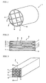
- Fig. 1 is a schematic perspective view showing an embodiment of a honeycomb structure 1 of the present invention.
- the honeycomb structure 1 is formed by bonding a plurality of honeycomb segments 2 by means of bonding layers 9 formed of bonding materials. After bonding the honeycomb segments 2 by means of the bonding materials, the segments are ground to have a section such as a circular section, an elliptic section, or a triangular section, and an outer peripheral surface is coated with a coating material 4.
- this honeycomb structure 1 when the structure is disposed in a channel of an exhaust gas from a diesel engine, it is possible to trap particulates containing soot discharged from the diesel engine.
- each honeycomb segment 2 has a large number of cells (through channels) 5 partitioned by porous partition walls 6.
- the cells 5 extend through the honeycomb segment 2 in an axial direction, and end portions of adjacent cells 5 on one side are alternately plugged by plugging materials 7. That is, in one cell 5, a left end portion is opened, whereas a right end portion is plugged with the plugging material 7. In another cell 5 adjacent to this cell, the left end portion is plugged with the plugging material 7, whereas the right end portion is opened. Since the cells are plugged in this manner, each end face of the honeycomb segment 2 exhibits a checkered pattern as shown in Fig. 4 .
- the exhaust gas flows into the cells 5 of each honeycomb segment 2 from a left side, and moves to a right side. That is, in Fig. 2 , the left side of the honeycomb segment 2 constitutes an inlet of the exhaust gas, and the exhaust gas flows into the honeycomb segment 2 from the cells 5 opened without being plugged with the plugging materials 7.
- the exhaust gas which has flown into the cells 5 passes through the porous partition walls 6 to flow out of the other cells.
- the segment 2 may have an appropriate sectional shape such as a triangular section or a hexagonal section.
- the cell 5 can have a sectional shape such as a triangular shape, a hexagonal shape, a circular shape, an elliptical shape, or another shape.
- the cells do not have to be plugged every other cell, and predetermined cells may be plugged. Therefore, the checkered pattern shown in Fig. 4 does not have to be exhibited.
- the honeycomb segment 2 As a material of the honeycomb segment 2, from the viewpoints of strength and heat resistance, it is preferable to use one kind selected from the group consisting of silicon carbide, a silicon-silicon carbide based composite material, silicon nitride, cordierite, mullite, alumina, spinel, a silicon carbide-cordierite-based composite material, a silicon-silicon carbide composite material, lithium aluminum silicate, aluminum titanate, and an Fe-Cr-Al-based metal, or a combination thereof. Among them, silicon carbide or the silicon-silicon carbide based composite is especially preferably used.
- a material similar to that of the honeycomb segment 2 may be used.
- a ceramic selected from the group consisting of silicon carbide, silicon nitride, cordierite, alumina, mullite, zirconia, zirconium phosphate, aluminum titanate, titania, silica and combinations thereof, a nickel-based metal, or metallic Si-SiC can preferably be used.
- the honeycomb segments 2 are bonded.
- the bonding material may be applied to the outer surfaces of the respective adjacent honeycomb segments 2, or to one of facing outer surfaces of the adjacent honeycomb segments 2.
- the application to only one of the facing surfaces is preferable in that a use amount of the bonding material can preferably be saved.
- a binder such as methyl cellulose, hydroxypropoxyl cellulose, hydroxyethyl cellulose, carboxymethyl cellulose, polyvinyl alcohol, or the like, surfactant, water and the like are added to the selected material to form puddle having plasticity.
- the puddle is extruded and formed into a honeycomb shape having a large number of cells 5 partitioned by the partition walls 6 and extending through the shape in an axial direction.
- This honeycomb-shaped formed body is plugged with the plugging material 7.
- the plugging can be conducted by masking cells that are not to be plugged, and immersing an end face of the honeycomb segment 2 in a slurry-state plugging material to fill the open cells 5. From a viewpoint of simplification of steps, the plugging is preferably performed before firing the honeycomb segment 2 as described later.
- the article After the plugging with the plugging material 7, the article is dried with hot air or the like and then sintered at a high temperature to form the honeycomb segment 2.
- honeycomb segment 2 After the honeycomb segment 2 is prepared as described above, a slurry-state bonding material is applied to the outer surface of the honeycomb segment 2, and a plurality of honeycomb segments 2 are assembled so as to obtain a predetermined three-dimensional shape. After the assembled segments are attached to one another under pressure, they are heated and dried. Accordingly, a bonded body is prepared in which the plurality of honeycomb segments 2 are bonded.
- a three-point bending strength in a formed bonding layer is set to 5 MPa or more, and a shearing strength of a bonded portion including the bonding layer and outer walls sandwiching the layer between opposite sides is set to 1 MPa or more. Since the three-point bending strength of the bonding layer is set to 5 MPa or more, and the shearing strength of the bonded portion is set to 1 MPa or more, strength of the bonded portion increases, and large thermal shock resistance can be imparted. Therefore, cracks can be inhibited from being generated in the bonded portions of the honeycomb segments 2.
- the bonding material contains inorganic particles, an oxide fiber, and a colloidal oxide.
- the inorganic particles for example, a ceramic selected from the group consisting of silicon carbide, silicon nitride, cordierite, alumina, mullite, zirconia, zirconium phosphate, aluminum titanate, titania, and combinations thereof, an Fe-Cr-Al type metal, a nickel-based metal, or metallic Si-SiC can preferably be used.
- ceramic fibers such as aluminosilicate, silica, alumina, and mullite can preferably be used.
- colloidal oxide for example, silica sol, alumina sol or the like can preferably be used.
- a foamed resin is preferably added to the bonding material.
- the bonding material contains the foamed resin, it is possible to reduce Young's modulus of the bonding layer 9 formed by curing the bonding material.
- the bonding material has a satisfactory ductility, wettability of the bonding material and the honeycomb segment 2 is enhanced, and bonding strengths of the honeycomb segments 2 by the bonding layers 9 increase. Consequently, thermal shock resistance properties of the bonded portions of the honeycomb segments 2 are enhanced, and cracks can be inhibited from being generated in the bonded portions.
- the foamed resin for example, an acrylonitrile-based plastic balloon made of an acrylonitrile-methyl methacrylate copolymer or the like can preferably be used.
- an organic binder may be added to the bonding material.
- the organic binder methyl cellulose, ethyl cellulose, hydroxyethyl cellulose, carboxymethyl cellulose, hydroxypropoxyl methyl cellulose, polyvinyl alcohol or the like can preferably be used.
- the bonded body obtained by bonding the plurality of honeycomb segments 2 with the bonding materials is preferably thermally treated by heating.
- the heat treatment is performed by leaving the bonded body to stand at a high temperature of 400 to 1200°C for about ten minutes. Since the bonding material contains the inorganic particles, the oxide fiber, and the colloidal oxide mentioned above, the strength of the bonding layer 9 itself formed of the bonding material increases by the heat treatment, as well as the bonding strength in the bonded portion of the honeycomb segment 2 increases. This tendency becomes remarkable especially in a case where the colloidal oxide is contained.
- the three-point bending strength of the bonding layer 9 and the shearing strength of the bonded portion can be set to 5 MPa or more and 1 MPa or more, respectively, and the cracks can be inhibited from being generated in the bonded portions of the honeycomb segments 2. It is to be noted that such heat treatment may be performed after the next step of coating outer peripheries of the segments.
- the bonded body of the honeycomb segments 2 After preparing the bonded body of the honeycomb segments 2 in this manner, the bonded body is ground, an outer peripheral surface of the body is coated with the coating material 4, and the body is heated and dried. Thus, the honeycomb structure 1 shown in FIG. 1 can be prepared. In this case, a material similar to the bonding material can be used as the coating material 4.
- the three-point bending strength in the bonding layer of the honeycomb segment 2 is 5 MPa or more, and the shearing strength of the bonded portion is 1 MPa or more. Since the strength of the bonded portion is large, and the thermal shock resistance of the bonded portion increases, any crack is not generated in the bonded portion of the honeycomb segment 2 even when a peeling stress acts owing to a temperature difference between an outer peripheral portion and an inner peripheral portion of the honeycomb structure 1 in a temperature drop step after performing a heat treatment such as calcinating of a catalyst. Consequently, a satisfactory honeycomb structure can be produced as a filter.
- An object of the present invention is to prevent the cracks in the bonded portions, and the present invention can be applied to a honeycomb structure such as a catalyst carrier in which any cell is not plugged in the same manner as in a filter type of honeycomb structure as long as the honeycomb structure is of a bounded type.
- SiC powder and metal Si powder was mixed together at a weight ratio of 80:20.
- starch as a pore-forming agent and resin foam were added.
- methyl cellulose, hydroxypropoxyl methyl cellulose, a surfactant, and water were added to prepare puddle having plasticity. This puddle was subjected to extrusion, the extrudate was dried using a microwave and hot air to obtain a honeycomb segment 2 having a partition wall 6 thickness of 310 ⁇ m, a cell density of about 46.5 cells/cm 2 (300 cells/in. 2 ), a square section of 35 mm ⁇ 35 mm and a length of 152 mm.
- each honeycomb segment was degreased at about 400°C in the ambient atmosphere, then fired at about 1,450°C in an Ar inert atmosphere to obtain the honeycomb segment 2 of Si-bonded SiC.
- SiC powder as inorganic particles, an aluminosilicate fiber as an oxide fiber, an aqueous solution containing 40% by mass of silica gel as a colloidal oxide, clay, and foamed resin were mixed, followed by adding water.
- the resultant mixture was kneaded using a mixer for 30 minutes to obtain bonding materials A to C having compositions shown in Table 1.
- silica gel means an aqueous solution containing 40% by mass of silica gel.
- honeycomb segments 2 were bonded using the bonding material shown in Table 1.
- the segments were dried at 200°C for two hours to obtain honeycomb filters (Filters 1 to 3).
- Filter 1, Filter 2, and Filter 3 were bonded using Bonding Material A, Bonding Material B, and Bonding Material C, respectively.
- Filters 1 and 3 were thermally treated at 700°C for ten minutes to obtain Filters 4 and 5.
- Filter 3 was thermally treated at 300°C for ten minutes to obtain Filter 6.
- Ten bonding layers were cut as samples for a strength test from each filter, and each bonding layer was measured for a three-point bending strength according to JIS R1601. Furthermore, a bonded portion including the bonding layer and outer walls on opposite sides of the layer was cut out to measure a shearing strength. To be more specific, as shown in FIG. 5 , a bonding layer 9 and honeycomb segments 2 on opposite sides of the layer having predetermined sizes were cut from each filter and set on a shearing strength measurement jig 10.
- One honeycomb segment 2 was fixed, a load was applied to the other honeycomb segment 2 in the arrow direction by an autograph, a load at a time when the bonded portion was sheared/destroyed was measured, and the shearing strength of the bonded portion was calculated from the value.
- thermal shock test an electric furnace spalling test was conducted.
- a sample was disposed in an electric furnace at a predetermined temperature, and taken out at room temperature after one hour to observe a crack generated state.
- the maximum temperature at which any crack was not generated was set as the limit temperature. Results are shown in Table 2.
- the limit temperature in the electric furnace spalling test is 550°C or more. It is shown that in a case where a stress generated in the bonded portion in a catalyst calcinating step is calculated, since the stress corresponds to that at 550°C in the electric furnace spalling test, the three-point bending strength of the bonded portion needs to be 5 MPa or more, and the shearing strength needs to be 1 MPa or more. Moreover, when the filter is thermally treated, the strength of the bonded portion can be enhanced, and the thermal shock resistance of the filter can be secured.
- the honeycomb structure of the present invention has high thermal shock resistance
- the structure can be applied to various applications such as a DPF and a catalyst carrier.
- the production method of a honeycomb structure of the present invention can preferably be applied to manufacture of such a honeycomb structure having high thermal shock resistance.
Landscapes
- Chemical & Material Sciences (AREA)
- Engineering & Computer Science (AREA)
- Ceramic Engineering (AREA)
- Chemical Kinetics & Catalysis (AREA)
- Structural Engineering (AREA)
- Organic Chemistry (AREA)
- Materials Engineering (AREA)
- Manufacturing & Machinery (AREA)
- Inorganic Chemistry (AREA)
- Geology (AREA)
- Life Sciences & Earth Sciences (AREA)
- Combustion & Propulsion (AREA)
- Mechanical Engineering (AREA)
- General Engineering & Computer Science (AREA)
- Health & Medical Sciences (AREA)
- Toxicology (AREA)
- Filtering Materials (AREA)
- Processes For Solid Components From Exhaust (AREA)
- Filtering Of Dispersed Particles In Gases (AREA)
- Ceramic Products (AREA)
- Catalysts (AREA)
Description
- The present invention relates to a honeycomb structure in which a plurality of honeycomb segments are bonded, more particularly to a honeycomb structure in which honeycomb segments are bonded with a large bonding force and which is superior in thermal shock resistance.
- This type of honeycomb structure has an application as a trapping filter such as a diesel particulate filter (DPF). There is also an application as an exhaust gas purifying catalyst carrier. The DPF is incorporated in an exhaust system of a diesel engine as a filter which traps particulates contained in an exhaust gas from a diesel engine or the like to remove the particulates. The exhaust gas purifying catalyst carrier carries a catalyst for purifying, for example, nitrogen oxide, hydrocarbon, and carbon monoxide in the exhaust gas from a gasoline engine and is incorporated in the exhaust system.
- In general, the trapping filter is not of a bonded type in which a plurality of honeycomb segments are bonded in parallel, and is integrally constituted. However, when the filter is used as a DPF, the bonded type is preferably used in order to secure thermal shock resistance. Also when the filter is used as a catalyst carrier, the bonded type can be used in a large-sized type.
- The honeycomb structure for the DPF is usually structured by bonding a plurality of porous honeycomb segments made of silicon carbide or the like by means of a bonding material, forming a structure into a predetermined shape such as a circular sectional shape, and coating periphery with a coating material. Each honeycomb segment has a large number of cells (through channels). The respective cells are partitioned by porous partition walls and extend in an axial direction. End portions of the cells are alternately plugged. That is, one end portion of a certain cell is opened, whereas the other end portion of the cell is plugged. As to another cell adjacent to the cell, one end portion is plugged, but the other end portion is opened.
- According to such structure, when the exhaust gas flows into the cell from the opened end portion, the exhaust gas passes through the porous partition wall to flow out of another cell, and the particulates in the exhaust gas are trapped in the partition walls during the passing of the gas through the partition walls. Therefore, the exhaust gas can be purified. In the honeycomb structure for the DPF, the partition walls carry the catalysts in order to promote calcinating and removing of the trapped particulates in many cases. On the other hand, in the catalyst carrier, the cells are not plugged, and the catalysts are carried by the partition walls to purify the exhaust gas.
- In Japanese Patent No.
3121497 - When a catalyst is carried by such a honeycomb structure, a catalyst such as a platinum metal and an alkaline earth metal is calcinated on the honeycomb structure. The catalysts are calcinated by performing a heat treatment at about 400 to 600°C after immersing the honeycomb structure into catalyst slurry, spraying catalyst slurry onto the honeycomb structure, or sucking catalyst slurry to pass the slurry through the honeycomb structure.
- [Patent Document 1]
JP-B-3121497 - After calcinating the catalyst onto the honeycomb structure, the honeycomb structure is cooled. During the cooling, cracks are sometimes generated. Moreover, there is a problem that, when such cracks are generated, the honeycomb structure cannot function as a filter or a catalyst carrier.
- As to such generation of the cracks, the honeycomb structure is distorted owing to a temperature difference between an outer peripheral portion and an inner peripheral portion of the honeycomb structure when the outer peripheral portion of the honeycomb structure is cooled in a temperature drop step after the calcinating. A difference in rigidity or thermal expansion coefficient between a honeycomb segment and a bonding layer generates especially large stress to peel or displace the honeycomb segment and the bonding layer from each other in a bonded portion. When this stress exceeds strength of the bonded portion, the cracks are generated.
- The present invention has been developed in consideration of such a conventional problem and aims to provide a honeycomb structure capable of inhibiting cracks from being generated during calcinating of a catalyst, and a method of manufacturing the structure.
- According to the present invention, there is provided a honeycomb structure comprising a plurality of honeycomb segments having a plurality of cells partitioned by porous partition walls and functioning as fluid channels and outer walls the honeycomb segments being bonded to one another by means of a bonding material containing a ceramic as a main component, wherein a three-point bending strength of a bonding layer formed of the bonding material is 5 MPa or more, and a shearing strength of a bonded portion including the bonding layer and the outer walls sandwiching this bonding layer therebetween is 1 MPa or more.
- In the present invention, the bonding material contains inorganic particles, an oxide fiber, and a colloidal oxide. The bonding material also preferably contains a foamed resin.
- Moreover, according to the present invention, there is provided a method of manufacturing a honeycomb structure comprising a plurality of honeycomb segments having a plurality of cells partitioned by porous partition walls and functioning as fluid channels, the honeycomb segments bonded to one another by means of a bonding material containing a ceramic as a main component, wherein a heat treatment at a temperature of 400 to 1200°C is performed in a state that the plurality of honeycomb segments are bonded by means of the bonding material.
- In the honeycomb structure according to the present invention, since the three-point bending strength of the bonding layer of the honeycomb segment is 5 MPa or more, and the shearing strength of the bonded portion including the bonding layer and the outer walls sandwiching this layer therebetween is 1 MPa or more, thermal shock resistance is high, and cracks are inhibited from being generated in the bonded portion of the honeycomb segment. According to the method of manufacturing the honeycomb structure of the present invention, such honeycomb structure having high thermal shock resistance can easily be manufactured.
-
-
Fig. 1 is a perspective view showing an embodiment of a honeycomb structure of the present invention; -
Fig. 2 is a sectional view of a honeycomb segment along the line A-A ofFig. 3 ; -
Fig. 3 is a perspective view of a honeycomb segment; -
Fig. 4 is an end face view of a honeycomb structure; and -
Fig. 5 is a schematic diagram showing a method of measuring shearing strength. -
- 1: Honeycomb structure
- 2: Honeycomb segment
- 5: Cell
- 6: Partition wall
- 7: Plugging material
- 9: Bonding layer
- 10: Shearing strength measuring jig
-
Fig. 1 is a schematic perspective view showing an embodiment of ahoneycomb structure 1 of the present invention. Thehoneycomb structure 1 is formed by bonding a plurality ofhoneycomb segments 2 by means of bondinglayers 9 formed of bonding materials. After bonding thehoneycomb segments 2 by means of the bonding materials, the segments are ground to have a section such as a circular section, an elliptic section, or a triangular section, and an outer peripheral surface is coated with acoating material 4. - In a case where this
honeycomb structure 1 is used as a DPF, when the structure is disposed in a channel of an exhaust gas from a diesel engine, it is possible to trap particulates containing soot discharged from the diesel engine. - As shown in
Figs. 2 and 3 , eachhoneycomb segment 2 has a large number of cells (through channels) 5 partitioned byporous partition walls 6. Thecells 5 extend through thehoneycomb segment 2 in an axial direction, and end portions ofadjacent cells 5 on one side are alternately plugged byplugging materials 7. That is, in onecell 5, a left end portion is opened, whereas a right end portion is plugged with theplugging material 7. In anothercell 5 adjacent to this cell, the left end portion is plugged with theplugging material 7, whereas the right end portion is opened. Since the cells are plugged in this manner, each end face of thehoneycomb segment 2 exhibits a checkered pattern as shown inFig. 4 . - When the
honeycomb structure 1 withsuch honeycomb segments 2 assembled is disposed in the channel of the exhaust gas, the exhaust gas flows into thecells 5 of eachhoneycomb segment 2 from a left side, and moves to a right side. That is, inFig. 2 , the left side of thehoneycomb segment 2 constitutes an inlet of the exhaust gas, and the exhaust gas flows into thehoneycomb segment 2 from thecells 5 opened without being plugged with theplugging materials 7. The exhaust gas which has flown into thecells 5 passes through theporous partition walls 6 to flow out of the other cells. When the exhaust gas passes through thepartition walls 6, soot containing particulates in the exhaust gas is trapped by thepartition walls 6. Therefore, the exhaust gas can be purified. - It is to be noted that, though the shown
honeycomb segment 2 has a square section, the segment may have an appropriate sectional shape such as a triangular section or a hexagonal section. Thecell 5 can have a sectional shape such as a triangular shape, a hexagonal shape, a circular shape, an elliptical shape, or another shape. Moreover, the cells do not have to be plugged every other cell, and predetermined cells may be plugged. Therefore, the checkered pattern shown inFig. 4 does not have to be exhibited. - As a material of the
honeycomb segment 2, from the viewpoints of strength and heat resistance, it is preferable to use one kind selected from the group consisting of silicon carbide, a silicon-silicon carbide based composite material, silicon nitride, cordierite, mullite, alumina, spinel, a silicon carbide-cordierite-based composite material, a silicon-silicon carbide composite material, lithium aluminum silicate, aluminum titanate, and an Fe-Cr-Al-based metal, or a combination thereof. Among them, silicon carbide or the silicon-silicon carbide based composite is especially preferably used. - As the plugging
material 7, a material similar to that of thehoneycomb segment 2 may be used. For example, a ceramic selected from the group consisting of silicon carbide, silicon nitride, cordierite, alumina, mullite, zirconia, zirconium phosphate, aluminum titanate, titania, silica and combinations thereof, a nickel-based metal, or metallic Si-SiC can preferably be used. - By applying a bonding material to an outer surface of each
honeycomb segment 2, thehoneycomb segments 2 are bonded. The bonding material may be applied to the outer surfaces of the respectiveadjacent honeycomb segments 2, or to one of facing outer surfaces of theadjacent honeycomb segments 2. The application to only one of the facing surfaces is preferable in that a use amount of the bonding material can preferably be saved. - In manufacturing the
honeycomb segment 2, a binder such as methyl cellulose, hydroxypropoxyl cellulose, hydroxyethyl cellulose, carboxymethyl cellulose, polyvinyl alcohol, or the like, surfactant, water and the like are added to the selected material to form puddle having plasticity. The puddle is extruded and formed into a honeycomb shape having a large number ofcells 5 partitioned by thepartition walls 6 and extending through the shape in an axial direction. - This honeycomb-shaped formed body is plugged with the plugging
material 7. The plugging can be conducted by masking cells that are not to be plugged, and immersing an end face of thehoneycomb segment 2 in a slurry-state plugging material to fill theopen cells 5. From a viewpoint of simplification of steps, the plugging is preferably performed before firing thehoneycomb segment 2 as described later. - After the plugging with the plugging
material 7, the article is dried with hot air or the like and then sintered at a high temperature to form thehoneycomb segment 2. - After the
honeycomb segment 2 is prepared as described above, a slurry-state bonding material is applied to the outer surface of thehoneycomb segment 2, and a plurality ofhoneycomb segments 2 are assembled so as to obtain a predetermined three-dimensional shape. After the assembled segments are attached to one another under pressure, they are heated and dried. Accordingly, a bonded body is prepared in which the plurality ofhoneycomb segments 2 are bonded. - In this case, a three-point bending strength in a formed bonding layer is set to 5 MPa or more, and a shearing strength of a bonded portion including the bonding layer and outer walls sandwiching the layer between opposite sides is set to 1 MPa or more. Since the three-point bending strength of the bonding layer is set to 5 MPa or more, and the shearing strength of the bonded portion is set to 1 MPa or more, strength of the bonded portion increases, and large thermal shock resistance can be imparted. Therefore, cracks can be inhibited from being generated in the bonded portions of the
honeycomb segments 2. The bonding material contains inorganic particles, an oxide fiber, and a colloidal oxide. - As for the inorganic particles, for example, a ceramic selected from the group consisting of silicon carbide, silicon nitride, cordierite, alumina, mullite, zirconia, zirconium phosphate, aluminum titanate, titania, and combinations thereof, an Fe-Cr-Al type metal, a nickel-based metal, or metallic Si-SiC can preferably be used.
- As the oxide fiber, ceramic fibers such as aluminosilicate, silica, alumina, and mullite can preferably be used.
- As the colloidal oxide, for example, silica sol, alumina sol or the like can preferably be used.
- Furthermore, a foamed resin is preferably added to the bonding material. When the bonding material contains the foamed resin, it is possible to reduce Young's modulus of the
bonding layer 9 formed by curing the bonding material. In addition to this, the bonding material has a satisfactory ductility, wettability of the bonding material and thehoneycomb segment 2 is enhanced, and bonding strengths of thehoneycomb segments 2 by the bonding layers 9 increase. Consequently, thermal shock resistance properties of the bonded portions of thehoneycomb segments 2 are enhanced, and cracks can be inhibited from being generated in the bonded portions. As the foamed resin, for example, an acrylonitrile-based plastic balloon made of an acrylonitrile-methyl methacrylate copolymer or the like can preferably be used. - Furthermore, if necessary, an organic binder may be added to the bonding material. As the organic binder, methyl cellulose, ethyl cellulose, hydroxyethyl cellulose, carboxymethyl cellulose, hydroxypropoxyl methyl cellulose, polyvinyl alcohol or the like can preferably be used.
- The bonded body obtained by bonding the plurality of
honeycomb segments 2 with the bonding materials is preferably thermally treated by heating. The heat treatment is performed by leaving the bonded body to stand at a high temperature of 400 to 1200°C for about ten minutes. Since the bonding material contains the inorganic particles, the oxide fiber, and the colloidal oxide mentioned above, the strength of thebonding layer 9 itself formed of the bonding material increases by the heat treatment, as well as the bonding strength in the bonded portion of thehoneycomb segment 2 increases. This tendency becomes remarkable especially in a case where the colloidal oxide is contained. Since the strength of thebonding layer 9 itself and the bonding strength of the bonded portion of thehoneycomb segment 2 increase in this manner, the three-point bending strength of thebonding layer 9 and the shearing strength of the bonded portion can be set to 5 MPa or more and 1 MPa or more, respectively, and the cracks can be inhibited from being generated in the bonded portions of thehoneycomb segments 2. It is to be noted that such heat treatment may be performed after the next step of coating outer peripheries of the segments. - After preparing the bonded body of the
honeycomb segments 2 in this manner, the bonded body is ground, an outer peripheral surface of the body is coated with thecoating material 4, and the body is heated and dried. Thus, thehoneycomb structure 1 shown inFIG. 1 can be prepared. In this case, a material similar to the bonding material can be used as thecoating material 4. - In a case of loading the catalyst on the
honeycomb structure 1 prepared in this manner, the three-point bending strength in the bonding layer of thehoneycomb segment 2 is 5 MPa or more, and the shearing strength of the bonded portion is 1 MPa or more. Since the strength of the bonded portion is large, and the thermal shock resistance of the bonded portion increases, any crack is not generated in the bonded portion of thehoneycomb segment 2 even when a peeling stress acts owing to a temperature difference between an outer peripheral portion and an inner peripheral portion of thehoneycomb structure 1 in a temperature drop step after performing a heat treatment such as calcinating of a catalyst. Consequently, a satisfactory honeycomb structure can be produced as a filter. It is to be noted that the embodiment of the present invention has been described with the example of the DPF. An object of the present invention is to prevent the cracks in the bonded portions, and the present invention can be applied to a honeycomb structure such as a catalyst carrier in which any cell is not plugged in the same manner as in a filter type of honeycomb structure as long as the honeycomb structure is of a bounded type. - As a raw material in this example, SiC powder and metal Si powder was mixed together at a weight ratio of 80:20. To the powder, starch as a pore-forming agent and resin foam were added. Further, to this powder, methyl cellulose, hydroxypropoxyl methyl cellulose, a surfactant, and water were added to prepare puddle having plasticity. This puddle was subjected to extrusion, the extrudate was dried using a microwave and hot air to obtain a
honeycomb segment 2 having apartition wall 6 thickness of 310 µm, a cell density of about 46.5 cells/cm2 (300 cells/in.2), a square section of 35 mm × 35 mm and a length of 152 mm. - In the
honeycomb segment 2, theadjacent cells 5 were sealed with the material similar to that for use in manufacturing thehoneycomb segment 2 in one end on the opposite side so that the end surfaces had checkered patterns. After being dried, each honeycomb segment was degreased at about 400°C in the ambient atmosphere, then fired at about 1,450°C in an Ar inert atmosphere to obtain thehoneycomb segment 2 of Si-bonded SiC. - On the other hand, SiC powder as inorganic particles, an aluminosilicate fiber as an oxide fiber, an aqueous solution containing 40% by mass of silica gel as a colloidal oxide, clay, and foamed resin were mixed, followed by adding water. The resultant mixture was kneaded using a mixer for 30 minutes to obtain bonding materials A to C having compositions shown in Table 1. It is to be noted that in Table 1 silica gel means an aqueous solution containing 40% by mass of silica gel.
-
[Table 1] Bonding materials No. SiC powder [% by mass] Aluminosilicate fiber [% by mass] Silica gel [% by mass] Foamed resin [% by mass] Clay [% by mass] Water [% by mass] A 41 25 23 0 1 10 B 40 24 23 1 1 10 C 45 26 10 0 1 18 - Next, the
honeycomb segments 2 were bonded using the bonding material shown in Table 1. In the bonding, after bonding a plurality of segments in such a manner that a thickness of thebonding layer 9 was 1 mm, the segments were dried at 200°C for two hours to obtain honeycomb filters (Filters 1 to 3). It is to be noted thatFilter 1,Filter 2, and Filter 3 were bonded using Bonding Material A, Bonding Material B, and Bonding Material C, respectively.Filters 1 and 3 were thermally treated at 700°C for ten minutes to obtainFilters Filter 6. - Ten bonding layers were cut as samples for a strength test from each filter, and each bonding layer was measured for a three-point bending strength according to JIS R1601. Furthermore, a bonded portion including the bonding layer and outer walls on opposite sides of the layer was cut out to measure a shearing strength. To be more specific, as shown in
FIG. 5 , abonding layer 9 andhoneycomb segments 2 on opposite sides of the layer having predetermined sizes were cut from each filter and set on a shearingstrength measurement jig 10. Onehoneycomb segment 2 was fixed, a load was applied to theother honeycomb segment 2 in the arrow direction by an autograph, a load at a time when the bonded portion was sheared/destroyed was measured, and the shearing strength of the bonded portion was calculated from the value. - Furthermore, as a thermal shock test, an electric furnace spalling test was conducted. In this test, a sample was disposed in an electric furnace at a predetermined temperature, and taken out at room temperature after one hour to observe a crack generated state. In this example, the maximum temperature at which any crack was not generated was set as the limit temperature. Results are shown in Table 2.
-
[Table 2] Filter No. Bending strength (average) [MPa] Shearing strength [MPa] Electric furnace spalling limit temperature [°C] Example 1 1 5.2 1.1 550 Example 2 2 6.1 1.4 550 Example 3 4 10.6 2.0 600 Example 4 5 7.1 1.7 550 Comparative Example 1 3 3.5 0.6 450 Comparative Example 2 6 4.2 0.8 500 - As seen from the results of Table 2, by setting the three-point bending strength of the bonding layer to 5 MPa or more and the shearing strength of the bonded portion to 1 MPa or more, the limit temperature in the electric furnace spalling test is 550°C or more. It is shown that in a case where a stress generated in the bonded portion in a catalyst calcinating step is calculated, since the stress corresponds to that at 550°C in the electric furnace spalling test, the three-point bending strength of the bonded portion needs to be 5 MPa or more, and the shearing strength needs to be 1 MPa or more. Moreover, when the filter is thermally treated, the strength of the bonded portion can be enhanced, and the thermal shock resistance of the filter can be secured.
- As described above, since the honeycomb structure of the present invention has high thermal shock resistance, the structure can be applied to various applications such as a DPF and a catalyst carrier. The production method of a honeycomb structure of the present invention can preferably be applied to manufacture of such a honeycomb structure having high thermal shock resistance.
Claims (3)
- A honeycomb structure (1) comprising a plurality of honeycomb segments (2) having a plurality of cells (5) partitioned by porous partition walls (6) and functioning as fluid channels and outer walls, the honeycomb segments (2) being bonded to one another by means of a bonding material containing a ceramic as a main component and containing inorganic particles, an oxide fiber, and a colloidal oxide,
wherein a three-point bending strength of a bonding layer (9) formed of the bonding material is 5 MPa or more, and a shearing strength of a bonded portion including the bonding layer (9) and the outer walls sandwiching this bonding layer (9) therebetween is 1 MPa or more. - The honeycomb structure (1) according to claim 1, wherein the bonding material contains a foamed resin.
- A method of manufacturing a honeycomb structure (1) comprising a plurality of honeycomb segments (2) having a plurality of cells (5) partitioned by porous partition walls (6) and functioning as fluid channels, the honeycomb segments (2) being bonded to one another by means of a bonding material containing a ceramic as a main component and containing inorganic particles, an oxide fiber, and a colloidal oxide, wherein a heat treatment at a temperature of 400 to 1200°C is performed in a state that the plurality of honeycomb segments (2) are bonded by means of the bonding material, the three-point bending strength of the bonding layer (9) formed of the bonding material being 5 MPa or more, and the shearing strength of a bonded portion including the bonding layer (9) and the outer walls sandwiching the bonding layer (9) therebetween being 1 MPa or more.
Priority Applications (1)
| Application Number | Priority Date | Filing Date | Title |
|---|---|---|---|
| PL05727066T PL1728544T3 (en) | 2004-03-23 | 2005-03-23 | Honeycomb structure and method for manufacturing the same |
Applications Claiming Priority (2)
| Application Number | Priority Date | Filing Date | Title |
|---|---|---|---|
| JP2004085529 | 2004-03-23 | ||
| PCT/JP2005/005208 WO2005089901A1 (en) | 2004-03-23 | 2005-03-23 | Honeycomb structure and method for manufacturing the same |
Publications (3)
| Publication Number | Publication Date |
|---|---|
| EP1728544A1 EP1728544A1 (en) | 2006-12-06 |
| EP1728544A4 EP1728544A4 (en) | 2007-10-17 |
| EP1728544B1 true EP1728544B1 (en) | 2013-12-25 |
Family
ID=34993480
Family Applications (1)
| Application Number | Title | Priority Date | Filing Date |
|---|---|---|---|
| EP05727066.2A Active EP1728544B1 (en) | 2004-03-23 | 2005-03-23 | Honeycomb structure and method for manufacturing the same |
Country Status (6)
| Country | Link |
|---|---|
| US (1) | US20070082174A1 (en) |
| EP (1) | EP1728544B1 (en) |
| JP (1) | JPWO2005089901A1 (en) |
| KR (1) | KR100818476B1 (en) |
| PL (1) | PL1728544T3 (en) |
| WO (1) | WO2005089901A1 (en) |
Families Citing this family (24)
| Publication number | Priority date | Publication date | Assignee | Title |
|---|---|---|---|---|
| JP4616752B2 (en) * | 2005-10-26 | 2011-01-19 | 日本碍子株式会社 | Honeycomb structure |
| KR20080073792A (en) * | 2005-12-14 | 2008-08-11 | 니뽄 가이시 가부시키가이샤 | Bonding material, process for producing the same, and honeycom structure made with the same |
| EP1806329A3 (en) * | 2006-01-05 | 2008-09-03 | Asahi Glass Company, Limited | Composition for ceramic bonding and ceramic bonded article |
| WO2007097162A1 (en) * | 2006-02-22 | 2007-08-30 | Ngk Insulators, Ltd. | Porous object based on silicon carbide and process for producing the same |
| WO2007097161A1 (en) * | 2006-02-22 | 2007-08-30 | Ngk Insulators, Ltd. | Porous object based on silicon carbide and process for producing the same |
| KR20090004935A (en) * | 2006-03-23 | 2009-01-12 | 니뽄 가이시 가부시키가이샤 | Honeycomb structure |
| EP2008987B1 (en) * | 2006-03-30 | 2018-06-27 | NGK Insulators, Ltd. | Honeycomb structure body |
| WO2007116665A1 (en) * | 2006-03-30 | 2007-10-18 | Ngk Insulators, Ltd. | Junction element, honeycomb segment junction element, and honeycomb structure therefrom |
| WO2008096851A1 (en) * | 2007-02-08 | 2008-08-14 | Ngk Insulators, Ltd. | Joining material composition, method for production of the joining material composition, jointed article, and method for production of the jointed article |
| EP1982966B1 (en) | 2007-03-29 | 2011-11-09 | Ibiden Co., Ltd. | Honeycomb structure and method of producing honeycomb structure |
| JP4975570B2 (en) * | 2007-03-29 | 2012-07-11 | イビデン株式会社 | Method for manufacturing honeycomb structure and honeycomb structure |
| WO2008126333A1 (en) | 2007-03-30 | 2008-10-23 | Ibiden Co., Ltd. | Honeycomb structure |
| JP4873326B2 (en) * | 2007-03-30 | 2012-02-08 | イビデン株式会社 | Honeycomb structure |
| WO2008155856A1 (en) | 2007-06-21 | 2008-12-24 | Ibiden Co., Ltd. | Honeycomb structure and process for producing the same |
| US7802478B2 (en) | 2007-06-27 | 2010-09-28 | Corning Incorporated | Methods and apparatus for measuring elastic modulus of non-solid ceramic materials by resonance |
| KR101251104B1 (en) * | 2007-11-08 | 2013-04-04 | (주)엘지하우시스 | Composition for particulate filter, SiC DPF and method for manufacturing the same |
| WO2009141897A1 (en) * | 2008-05-20 | 2009-11-26 | イビデン株式会社 | Honeycomb structure |
| FR2936956B1 (en) * | 2008-10-10 | 2010-11-12 | Saint Gobain Ct Recherches | PARTICLE FILTRATION DEVICE |
| ES2730079T3 (en) * | 2008-12-15 | 2019-11-08 | Unifrax I Llc | Honeycomb structure ceramic film cladding |
| JP6022985B2 (en) * | 2013-03-29 | 2016-11-09 | 日本碍子株式会社 | Honeycomb structure |
| JP6802075B2 (en) * | 2017-01-20 | 2020-12-16 | 日本碍子株式会社 | Honeycomb structure |
| JP6847724B2 (en) * | 2017-03-21 | 2021-03-24 | 日本碍子株式会社 | Sealed honeycomb structure |
| JP2020157260A (en) * | 2019-03-27 | 2020-10-01 | 日本碍子株式会社 | Method for producing honeycomb structure |
| RU2768416C1 (en) * | 2021-04-15 | 2022-03-24 | Акционерное общество «Обнинское научно-производственное предприятие «Технология» им. А.Г.Ромашина» | Heat-resistant three-layer honeycomb structure |
Citations (1)
| Publication number | Priority date | Publication date | Assignee | Title |
|---|---|---|---|---|
| EP0816065A1 (en) * | 1996-01-12 | 1998-01-07 | Ibiden Co, Ltd. | Ceramic structure |
Family Cites Families (7)
| Publication number | Priority date | Publication date | Assignee | Title |
|---|---|---|---|---|
| JP3121497B2 (en) * | 1994-07-14 | 2000-12-25 | イビデン株式会社 | Ceramic structure |
| US6099671A (en) * | 1998-05-20 | 2000-08-08 | Northrop Grumman Corporation | Method of adhering ceramic foams |
| JP2001096116A (en) * | 1999-09-29 | 2001-04-10 | Ibiden Co Ltd | Ceramic filter aggregate and honeycomb filter |
| KR100446205B1 (en) * | 1999-09-29 | 2004-08-31 | 이비덴 가부시키가이샤 | Honeycomb filter and ceramic filter assembly, and exaust gas cleaning apparatus |
| JP4167814B2 (en) * | 2001-03-22 | 2008-10-22 | イビデン株式会社 | Ceramic filter assembly |
| JP4246425B2 (en) * | 2001-10-15 | 2009-04-02 | 日本碍子株式会社 | Honeycomb filter |
| JP2003212672A (en) * | 2002-01-21 | 2003-07-30 | Ngk Insulators Ltd | Process for manufacturing porous ceramic structure |
-
2005
- 2005-03-23 JP JP2006511297A patent/JPWO2005089901A1/en active Pending
- 2005-03-23 PL PL05727066T patent/PL1728544T3/en unknown
- 2005-03-23 WO PCT/JP2005/005208 patent/WO2005089901A1/en not_active Application Discontinuation
- 2005-03-23 EP EP05727066.2A patent/EP1728544B1/en active Active
- 2005-03-23 KR KR1020067010529A patent/KR100818476B1/en active IP Right Grant
- 2005-03-23 US US10/578,576 patent/US20070082174A1/en not_active Abandoned
Patent Citations (1)
| Publication number | Priority date | Publication date | Assignee | Title |
|---|---|---|---|---|
| EP0816065A1 (en) * | 1996-01-12 | 1998-01-07 | Ibiden Co, Ltd. | Ceramic structure |
Also Published As
| Publication number | Publication date |
|---|---|
| US20070082174A1 (en) | 2007-04-12 |
| JPWO2005089901A1 (en) | 2008-01-31 |
| KR20060096087A (en) | 2006-09-05 |
| PL1728544T3 (en) | 2014-05-30 |
| EP1728544A1 (en) | 2006-12-06 |
| WO2005089901A1 (en) | 2005-09-29 |
| KR100818476B1 (en) | 2008-04-02 |
| EP1728544A4 (en) | 2007-10-17 |
Similar Documents
| Publication | Publication Date | Title |
|---|---|---|
| EP1728544B1 (en) | Honeycomb structure and method for manufacturing the same | |
| EP1795262B1 (en) | Honeycomb structure | |
| EP2008985B1 (en) | Bonded element and honeycomb sutructure using the same | |
| US8039086B2 (en) | Bonding material, process for producing the same, and honeycomb structure made with the same | |
| EP1997789B1 (en) | Honeycomb structure and bonding material to be used for the same | |
| EP1270202B1 (en) | Filter for purifying exhaust gas | |
| EP1780187B1 (en) | Honeycomb structure | |
| EP1839725B1 (en) | Honeycomb structure | |
| EP1550494B1 (en) | Honeycomb structure | |
| EP2006265B1 (en) | Bonded body | |
| EP1860082B1 (en) | Honeycomb structure | |
| EP1884275B1 (en) | Honeycomb structure body | |
| KR100762196B1 (en) | Honeycomb structure | |
| EP2123617B1 (en) | Joining material composition, method for production of the joining material composition, jointed article, and method for production of the jointed article | |
| EP1741479A2 (en) | Honeycomb structure | |
| EP2915792B1 (en) | Honeycomb structure | |
| EP1997790A1 (en) | Honeycomb structure | |
| EP1600433B1 (en) | Honeycomb structure | |
| JP2003275522A (en) | Ceramic filter assembly | |
| EP1790408A2 (en) | Honeycomb structure | |
| EP2133198A1 (en) | Assembly, method for production of the assembly, joint composition, and method for production of the joint composition | |
| EP2119688A1 (en) | Honeycomb segments joined body for dpf and bonding material composition for the joined body | |
| EP2233452A1 (en) | Honeycomb structure |
Legal Events
| Date | Code | Title | Description |
|---|---|---|---|
| PUAI | Public reference made under article 153(3) epc to a published international application that has entered the european phase |
Free format text: ORIGINAL CODE: 0009012 |
|
| 17P | Request for examination filed |
Effective date: 20060522 |
|
| AK | Designated contracting states |
Kind code of ref document: A1 Designated state(s): DE FR PL |
|
| DAX | Request for extension of the european patent (deleted) | ||
| RBV | Designated contracting states (corrected) |
Designated state(s): DE FR PL |
|
| A4 | Supplementary search report drawn up and despatched |
Effective date: 20070917 |
|
| 17Q | First examination report despatched |
Effective date: 20100204 |
|
| REG | Reference to a national code |
Ref country code: DE Ref legal event code: R079 Ref document number: 602005042245 Country of ref document: DE Free format text: PREVIOUS MAIN CLASS: B01D0039200000 Ipc: C04B0028240000 |
|
| RIC1 | Information provided on ipc code assigned before grant |
Ipc: C04B 111/00 20060101ALI20130422BHEP Ipc: C04B 38/00 20060101ALI20130422BHEP Ipc: F01N 3/28 20060101ALI20130422BHEP Ipc: B01D 39/20 20060101ALI20130422BHEP Ipc: C04B 35/80 20060101ALI20130422BHEP Ipc: C04B 28/24 20060101AFI20130422BHEP Ipc: C04B 35/565 20060101ALI20130422BHEP Ipc: C04B 35/626 20060101ALI20130422BHEP |
|
| GRAP | Despatch of communication of intention to grant a patent |
Free format text: ORIGINAL CODE: EPIDOSNIGR1 |
|
| INTG | Intention to grant announced |
Effective date: 20130712 |
|
| GRAS | Grant fee paid |
Free format text: ORIGINAL CODE: EPIDOSNIGR3 |
|
| GRAA | (expected) grant |
Free format text: ORIGINAL CODE: 0009210 |
|
| AK | Designated contracting states |
Kind code of ref document: B1 Designated state(s): DE FR PL |
|
| REG | Reference to a national code |
Ref country code: DE Ref legal event code: R096 Ref document number: 602005042245 Country of ref document: DE Effective date: 20140213 |
|
| REG | Reference to a national code |
Ref country code: PL Ref legal event code: T3 |
|
| REG | Reference to a national code |
Ref country code: DE Ref legal event code: R097 Ref document number: 602005042245 Country of ref document: DE |
|
| PLBE | No opposition filed within time limit |
Free format text: ORIGINAL CODE: 0009261 |
|
| STAA | Information on the status of an ep patent application or granted ep patent |
Free format text: STATUS: NO OPPOSITION FILED WITHIN TIME LIMIT |
|
| 26N | No opposition filed |
Effective date: 20140926 |
|
| REG | Reference to a national code |
Ref country code: DE Ref legal event code: R097 Ref document number: 602005042245 Country of ref document: DE Effective date: 20140926 |
|
| REG | Reference to a national code |
Ref country code: FR Ref legal event code: PLFP Year of fee payment: 12 |
|
| REG | Reference to a national code |
Ref country code: FR Ref legal event code: PLFP Year of fee payment: 13 |
|
| REG | Reference to a national code |
Ref country code: FR Ref legal event code: PLFP Year of fee payment: 14 |
|
| PGFP | Annual fee paid to national office [announced via postgrant information from national office to epo] |
Ref country code: PL Payment date: 20200129 Year of fee payment: 16 |
|
| PGFP | Annual fee paid to national office [announced via postgrant information from national office to epo] |
Ref country code: FR Payment date: 20200214 Year of fee payment: 16 |
|
| PG25 | Lapsed in a contracting state [announced via postgrant information from national office to epo] |
Ref country code: FR Free format text: LAPSE BECAUSE OF NON-PAYMENT OF DUE FEES Effective date: 20210331 |
|
| PG25 | Lapsed in a contracting state [announced via postgrant information from national office to epo] |
Ref country code: PL Free format text: LAPSE BECAUSE OF NON-PAYMENT OF DUE FEES Effective date: 20210323 |
|
| PGFP | Annual fee paid to national office [announced via postgrant information from national office to epo] |
Ref country code: DE Payment date: 20240130 Year of fee payment: 20 |