JP6847724B2 - Sealed honeycomb structure - Google Patents
Sealed honeycomb structure Download PDFInfo
- Publication number
- JP6847724B2 JP6847724B2 JP2017054567A JP2017054567A JP6847724B2 JP 6847724 B2 JP6847724 B2 JP 6847724B2 JP 2017054567 A JP2017054567 A JP 2017054567A JP 2017054567 A JP2017054567 A JP 2017054567A JP 6847724 B2 JP6847724 B2 JP 6847724B2
- Authority
- JP
- Japan
- Prior art keywords
- honeycomb
- bonding layer
- outer peripheral
- bonding
- sealing
- Prior art date
- Legal status (The legal status is an assumption and is not a legal conclusion. Google has not performed a legal analysis and makes no representation as to the accuracy of the status listed.)
- Active
Links
- 238000007789 sealing Methods 0.000 claims description 108
- 230000002093 peripheral effect Effects 0.000 claims description 101
- 238000005192 partition Methods 0.000 claims description 26
- 230000005484 gravity Effects 0.000 claims description 13
- 239000000463 material Substances 0.000 description 60
- 238000000034 method Methods 0.000 description 15
- 238000012360 testing method Methods 0.000 description 13
- 239000007789 gas Substances 0.000 description 12
- 239000003054 catalyst Substances 0.000 description 11
- 238000005259 measurement Methods 0.000 description 11
- 238000001816 cooling Methods 0.000 description 9
- 238000005304 joining Methods 0.000 description 9
- 239000004071 soot Substances 0.000 description 9
- 239000002994 raw material Substances 0.000 description 8
- 229910010271 silicon carbide Inorganic materials 0.000 description 8
- HBMJWWWQQXIZIP-UHFFFAOYSA-N silicon carbide Chemical compound [Si+]#[C-] HBMJWWWQQXIZIP-UHFFFAOYSA-N 0.000 description 7
- 239000004927 clay Substances 0.000 description 6
- 238000011156 evaluation Methods 0.000 description 6
- 230000008929 regeneration Effects 0.000 description 6
- 238000011069 regeneration method Methods 0.000 description 6
- 230000000052 comparative effect Effects 0.000 description 5
- 239000002131 composite material Substances 0.000 description 5
- 238000010304 firing Methods 0.000 description 5
- 230000003647 oxidation Effects 0.000 description 5
- 238000007254 oxidation reaction Methods 0.000 description 5
- 239000002002 slurry Substances 0.000 description 5
- XLYOFNOQVPJJNP-UHFFFAOYSA-N water Substances O XLYOFNOQVPJJNP-UHFFFAOYSA-N 0.000 description 5
- 239000011230 binding agent Substances 0.000 description 4
- 238000002485 combustion reaction Methods 0.000 description 4
- 230000008021 deposition Effects 0.000 description 4
- 238000010438 heat treatment Methods 0.000 description 4
- 238000004519 manufacturing process Methods 0.000 description 4
- 239000013618 particulate matter Substances 0.000 description 4
- 238000000746 purification Methods 0.000 description 4
- 239000002904 solvent Substances 0.000 description 4
- XUIMIQQOPSSXEZ-UHFFFAOYSA-N Silicon Chemical compound [Si] XUIMIQQOPSSXEZ-UHFFFAOYSA-N 0.000 description 3
- 239000011248 coating agent Substances 0.000 description 3
- 238000000576 coating method Methods 0.000 description 3
- 239000000843 powder Substances 0.000 description 3
- SBEQWOXEGHQIMW-UHFFFAOYSA-N silicon Chemical compound [Si].[Si] SBEQWOXEGHQIMW-UHFFFAOYSA-N 0.000 description 3
- 229910052710 silicon Inorganic materials 0.000 description 3
- 239000010703 silicon Substances 0.000 description 3
- 238000004901 spalling Methods 0.000 description 3
- 230000008646 thermal stress Effects 0.000 description 3
- 239000000654 additive Substances 0.000 description 2
- 230000000996 additive effect Effects 0.000 description 2
- 239000012298 atmosphere Substances 0.000 description 2
- 239000000919 ceramic Substances 0.000 description 2
- 230000002542 deteriorative effect Effects 0.000 description 2
- 230000000694 effects Effects 0.000 description 2
- 239000010419 fine particle Substances 0.000 description 2
- 238000000465 moulding Methods 0.000 description 2
- 238000012545 processing Methods 0.000 description 2
- 239000011347 resin Substances 0.000 description 2
- 229920005989 resin Polymers 0.000 description 2
- 229910000505 Al2TiO5 Inorganic materials 0.000 description 1
- OKTJSMMVPCPJKN-UHFFFAOYSA-N Carbon Chemical compound [C] OKTJSMMVPCPJKN-UHFFFAOYSA-N 0.000 description 1
- 229910052581 Si3N4 Inorganic materials 0.000 description 1
- VYPSYNLAJGMNEJ-UHFFFAOYSA-N Silicium dioxide Chemical compound O=[Si]=O VYPSYNLAJGMNEJ-UHFFFAOYSA-N 0.000 description 1
- JFBZPFYRPYOZCQ-UHFFFAOYSA-N [Li].[Al] Chemical compound [Li].[Al] JFBZPFYRPYOZCQ-UHFFFAOYSA-N 0.000 description 1
- 239000002250 absorbent Substances 0.000 description 1
- PNEYBMLMFCGWSK-UHFFFAOYSA-N aluminium oxide Inorganic materials [O-2].[O-2].[O-2].[Al+3].[Al+3] PNEYBMLMFCGWSK-UHFFFAOYSA-N 0.000 description 1
- 239000012300 argon atmosphere Substances 0.000 description 1
- 229910052799 carbon Inorganic materials 0.000 description 1
- 238000006555 catalytic reaction Methods 0.000 description 1
- 238000010531 catalytic reduction reaction Methods 0.000 description 1
- 229910010293 ceramic material Inorganic materials 0.000 description 1
- 239000008119 colloidal silica Substances 0.000 description 1
- 229910052878 cordierite Inorganic materials 0.000 description 1
- 238000005520 cutting process Methods 0.000 description 1
- 238000005238 degreasing Methods 0.000 description 1
- JSKIRARMQDRGJZ-UHFFFAOYSA-N dimagnesium dioxido-bis[(1-oxido-3-oxo-2,4,6,8,9-pentaoxa-1,3-disila-5,7-dialuminabicyclo[3.3.1]nonan-7-yl)oxy]silane Chemical compound [Mg++].[Mg++].[O-][Si]([O-])(O[Al]1O[Al]2O[Si](=O)O[Si]([O-])(O1)O2)O[Al]1O[Al]2O[Si](=O)O[Si]([O-])(O1)O2 JSKIRARMQDRGJZ-UHFFFAOYSA-N 0.000 description 1
- KZHJGOXRZJKJNY-UHFFFAOYSA-N dioxosilane;oxo(oxoalumanyloxy)alumane Chemical compound O=[Si]=O.O=[Si]=O.O=[Al]O[Al]=O.O=[Al]O[Al]=O.O=[Al]O[Al]=O KZHJGOXRZJKJNY-UHFFFAOYSA-N 0.000 description 1
- 239000002270 dispersing agent Substances 0.000 description 1
- 239000000428 dust Substances 0.000 description 1
- 238000001125 extrusion Methods 0.000 description 1
- 230000002349 favourable effect Effects 0.000 description 1
- 239000012530 fluid Substances 0.000 description 1
- 238000000227 grinding Methods 0.000 description 1
- 239000001866 hydroxypropyl methyl cellulose Substances 0.000 description 1
- 229920003088 hydroxypropyl methyl cellulose Polymers 0.000 description 1
- UFVKGYZPFZQRLF-UHFFFAOYSA-N hydroxypropyl methyl cellulose Chemical compound OC1C(O)C(OC)OC(CO)C1OC1C(O)C(O)C(OC2C(C(O)C(OC3C(C(O)C(O)C(CO)O3)O)C(CO)O2)O)C(CO)O1 UFVKGYZPFZQRLF-UHFFFAOYSA-N 0.000 description 1
- 235000010979 hydroxypropyl methyl cellulose Nutrition 0.000 description 1
- 238000002347 injection Methods 0.000 description 1
- 239000007924 injection Substances 0.000 description 1
- 239000012784 inorganic fiber Substances 0.000 description 1
- 238000000691 measurement method Methods 0.000 description 1
- QSHDDOUJBYECFT-UHFFFAOYSA-N mercury Chemical compound [Hg] QSHDDOUJBYECFT-UHFFFAOYSA-N 0.000 description 1
- 229910052753 mercury Inorganic materials 0.000 description 1
- 229910052751 metal Inorganic materials 0.000 description 1
- 239000002184 metal Substances 0.000 description 1
- 229910052863 mullite Inorganic materials 0.000 description 1
- 239000002245 particle Substances 0.000 description 1
- 239000004033 plastic Substances 0.000 description 1
- 239000011148 porous material Substances 0.000 description 1
- AABBHSMFGKYLKE-SNAWJCMRSA-N propan-2-yl (e)-but-2-enoate Chemical compound C\C=C\C(=O)OC(C)C AABBHSMFGKYLKE-SNAWJCMRSA-N 0.000 description 1
- 238000006722 reduction reaction Methods 0.000 description 1
- HQVNEWCFYHHQES-UHFFFAOYSA-N silicon nitride Chemical compound N12[Si]34N5[Si]62N3[Si]51N64 HQVNEWCFYHHQES-UHFFFAOYSA-N 0.000 description 1
- 238000000638 solvent extraction Methods 0.000 description 1
- 229910052596 spinel Inorganic materials 0.000 description 1
- 239000011029 spinel Substances 0.000 description 1
- 230000035882 stress Effects 0.000 description 1
- 239000000126 substance Substances 0.000 description 1
- 230000001629 suppression Effects 0.000 description 1
Images


Classifications
-
- F—MECHANICAL ENGINEERING; LIGHTING; HEATING; WEAPONS; BLASTING
- F01—MACHINES OR ENGINES IN GENERAL; ENGINE PLANTS IN GENERAL; STEAM ENGINES
- F01N—GAS-FLOW SILENCERS OR EXHAUST APPARATUS FOR MACHINES OR ENGINES IN GENERAL; GAS-FLOW SILENCERS OR EXHAUST APPARATUS FOR INTERNAL COMBUSTION ENGINES
- F01N3/00—Exhaust or silencing apparatus having means for purifying, rendering innocuous, or otherwise treating exhaust
- F01N3/02—Exhaust or silencing apparatus having means for purifying, rendering innocuous, or otherwise treating exhaust for cooling, or for removing solid constituents of, exhaust
- F01N3/021—Exhaust or silencing apparatus having means for purifying, rendering innocuous, or otherwise treating exhaust for cooling, or for removing solid constituents of, exhaust by means of filters
- F01N3/022—Exhaust or silencing apparatus having means for purifying, rendering innocuous, or otherwise treating exhaust for cooling, or for removing solid constituents of, exhaust by means of filters characterised by specially adapted filtering structure, e.g. honeycomb, mesh or fibrous
- F01N3/0222—Exhaust or silencing apparatus having means for purifying, rendering innocuous, or otherwise treating exhaust for cooling, or for removing solid constituents of, exhaust by means of filters characterised by specially adapted filtering structure, e.g. honeycomb, mesh or fibrous the structure being monolithic, e.g. honeycombs
-
- B01J35/56—
-
- B—PERFORMING OPERATIONS; TRANSPORTING
- B01—PHYSICAL OR CHEMICAL PROCESSES OR APPARATUS IN GENERAL
- B01D—SEPARATION
- B01D46/00—Filters or filtering processes specially modified for separating dispersed particles from gases or vapours
- B01D46/24—Particle separators, e.g. dust precipitators, using rigid hollow filter bodies
- B01D46/2403—Particle separators, e.g. dust precipitators, using rigid hollow filter bodies characterised by the physical shape or structure of the filtering element
- B01D46/2418—Honeycomb filters
- B01D46/2425—Honeycomb filters characterized by parameters related to the physical properties of the honeycomb structure material
- B01D46/2448—Honeycomb filters characterized by parameters related to the physical properties of the honeycomb structure material of the adhesive layers, i.e. joints between segments
-
- B—PERFORMING OPERATIONS; TRANSPORTING
- B01—PHYSICAL OR CHEMICAL PROCESSES OR APPARATUS IN GENERAL
- B01D—SEPARATION
- B01D46/00—Filters or filtering processes specially modified for separating dispersed particles from gases or vapours
- B01D46/24—Particle separators, e.g. dust precipitators, using rigid hollow filter bodies
- B01D46/2403—Particle separators, e.g. dust precipitators, using rigid hollow filter bodies characterised by the physical shape or structure of the filtering element
- B01D46/2418—Honeycomb filters
- B01D46/2451—Honeycomb filters characterized by the geometrical structure, shape, pattern or configuration or parameters related to the geometry of the structure
- B01D46/2466—Honeycomb filters characterized by the geometrical structure, shape, pattern or configuration or parameters related to the geometry of the structure of the adhesive layers, i.e. joints between segments
-
- B—PERFORMING OPERATIONS; TRANSPORTING
- B01—PHYSICAL OR CHEMICAL PROCESSES OR APPARATUS IN GENERAL
- B01D—SEPARATION
- B01D46/00—Filters or filtering processes specially modified for separating dispersed particles from gases or vapours
- B01D46/24—Particle separators, e.g. dust precipitators, using rigid hollow filter bodies
- B01D46/2403—Particle separators, e.g. dust precipitators, using rigid hollow filter bodies characterised by the physical shape or structure of the filtering element
- B01D46/2418—Honeycomb filters
- B01D46/2451—Honeycomb filters characterized by the geometrical structure, shape, pattern or configuration or parameters related to the geometry of the structure
- B01D46/2478—Structures comprising honeycomb segments
-
- B—PERFORMING OPERATIONS; TRANSPORTING
- B01—PHYSICAL OR CHEMICAL PROCESSES OR APPARATUS IN GENERAL
- B01D—SEPARATION
- B01D46/00—Filters or filtering processes specially modified for separating dispersed particles from gases or vapours
- B01D46/24—Particle separators, e.g. dust precipitators, using rigid hollow filter bodies
- B01D46/2403—Particle separators, e.g. dust precipitators, using rigid hollow filter bodies characterised by the physical shape or structure of the filtering element
- B01D46/2418—Honeycomb filters
- B01D46/2498—The honeycomb filter being defined by mathematical relationships
-
- B—PERFORMING OPERATIONS; TRANSPORTING
- B01—PHYSICAL OR CHEMICAL PROCESSES OR APPARATUS IN GENERAL
- B01D—SEPARATION
- B01D46/00—Filters or filtering processes specially modified for separating dispersed particles from gases or vapours
- B01D46/66—Regeneration of the filtering material or filter elements inside the filter
- B01D46/80—Chemical processes for the removal of the retained particles, e.g. by burning
- B01D46/82—Chemical processes for the removal of the retained particles, e.g. by burning with catalysts
-
- B—PERFORMING OPERATIONS; TRANSPORTING
- B01—PHYSICAL OR CHEMICAL PROCESSES OR APPARATUS IN GENERAL
- B01J—CHEMICAL OR PHYSICAL PROCESSES, e.g. CATALYSIS OR COLLOID CHEMISTRY; THEIR RELEVANT APPARATUS
- B01J37/00—Processes, in general, for preparing catalysts; Processes, in general, for activation of catalysts
- B01J37/02—Impregnation, coating or precipitation
- B01J37/0215—Coating
-
- C—CHEMISTRY; METALLURGY
- C04—CEMENTS; CONCRETE; ARTIFICIAL STONE; CERAMICS; REFRACTORIES
- C04B—LIME, MAGNESIA; SLAG; CEMENTS; COMPOSITIONS THEREOF, e.g. MORTARS, CONCRETE OR LIKE BUILDING MATERIALS; ARTIFICIAL STONE; CERAMICS; REFRACTORIES; TREATMENT OF NATURAL STONE
- C04B38/00—Porous mortars, concrete, artificial stone or ceramic ware; Preparation thereof
- C04B38/0006—Honeycomb structures
- C04B38/0012—Honeycomb structures characterised by the material used for sealing or plugging (some of) the channels of the honeycombs
-
- C—CHEMISTRY; METALLURGY
- C04—CEMENTS; CONCRETE; ARTIFICIAL STONE; CERAMICS; REFRACTORIES
- C04B—LIME, MAGNESIA; SLAG; CEMENTS; COMPOSITIONS THEREOF, e.g. MORTARS, CONCRETE OR LIKE BUILDING MATERIALS; ARTIFICIAL STONE; CERAMICS; REFRACTORIES; TREATMENT OF NATURAL STONE
- C04B41/00—After-treatment of mortars, concrete, artificial stone or ceramics; Treatment of natural stone
- C04B41/009—After-treatment of mortars, concrete, artificial stone or ceramics; Treatment of natural stone characterised by the material treated
-
- C—CHEMISTRY; METALLURGY
- C04—CEMENTS; CONCRETE; ARTIFICIAL STONE; CERAMICS; REFRACTORIES
- C04B—LIME, MAGNESIA; SLAG; CEMENTS; COMPOSITIONS THEREOF, e.g. MORTARS, CONCRETE OR LIKE BUILDING MATERIALS; ARTIFICIAL STONE; CERAMICS; REFRACTORIES; TREATMENT OF NATURAL STONE
- C04B41/00—After-treatment of mortars, concrete, artificial stone or ceramics; Treatment of natural stone
- C04B41/45—Coating or impregnating, e.g. injection in masonry, partial coating of green or fired ceramics, organic coating compositions for adhering together two concrete elements
- C04B41/50—Coating or impregnating, e.g. injection in masonry, partial coating of green or fired ceramics, organic coating compositions for adhering together two concrete elements with inorganic materials
- C04B41/5076—Coating or impregnating, e.g. injection in masonry, partial coating of green or fired ceramics, organic coating compositions for adhering together two concrete elements with inorganic materials with masses bonded by inorganic cements
- C04B41/5089—Silica sols, alkyl, ammonium or alkali metal silicate cements
-
- C—CHEMISTRY; METALLURGY
- C04—CEMENTS; CONCRETE; ARTIFICIAL STONE; CERAMICS; REFRACTORIES
- C04B—LIME, MAGNESIA; SLAG; CEMENTS; COMPOSITIONS THEREOF, e.g. MORTARS, CONCRETE OR LIKE BUILDING MATERIALS; ARTIFICIAL STONE; CERAMICS; REFRACTORIES; TREATMENT OF NATURAL STONE
- C04B41/00—After-treatment of mortars, concrete, artificial stone or ceramics; Treatment of natural stone
- C04B41/80—After-treatment of mortars, concrete, artificial stone or ceramics; Treatment of natural stone of only ceramics
- C04B41/81—Coating or impregnation
- C04B41/85—Coating or impregnation with inorganic materials
-
- F—MECHANICAL ENGINEERING; LIGHTING; HEATING; WEAPONS; BLASTING
- F01—MACHINES OR ENGINES IN GENERAL; ENGINE PLANTS IN GENERAL; STEAM ENGINES
- F01N—GAS-FLOW SILENCERS OR EXHAUST APPARATUS FOR MACHINES OR ENGINES IN GENERAL; GAS-FLOW SILENCERS OR EXHAUST APPARATUS FOR INTERNAL COMBUSTION ENGINES
- F01N3/00—Exhaust or silencing apparatus having means for purifying, rendering innocuous, or otherwise treating exhaust
- F01N3/02—Exhaust or silencing apparatus having means for purifying, rendering innocuous, or otherwise treating exhaust for cooling, or for removing solid constituents of, exhaust
- F01N3/021—Exhaust or silencing apparatus having means for purifying, rendering innocuous, or otherwise treating exhaust for cooling, or for removing solid constituents of, exhaust by means of filters
- F01N3/033—Exhaust or silencing apparatus having means for purifying, rendering innocuous, or otherwise treating exhaust for cooling, or for removing solid constituents of, exhaust by means of filters in combination with other devices
- F01N3/035—Exhaust or silencing apparatus having means for purifying, rendering innocuous, or otherwise treating exhaust for cooling, or for removing solid constituents of, exhaust by means of filters in combination with other devices with catalytic reactors, e.g. catalysed diesel particulate filters
-
- B—PERFORMING OPERATIONS; TRANSPORTING
- B01—PHYSICAL OR CHEMICAL PROCESSES OR APPARATUS IN GENERAL
- B01D—SEPARATION
- B01D2255/00—Catalysts
- B01D2255/90—Physical characteristics of catalysts
- B01D2255/915—Catalyst supported on particulate filters
- B01D2255/9155—Wall flow filters
-
- B—PERFORMING OPERATIONS; TRANSPORTING
- B01—PHYSICAL OR CHEMICAL PROCESSES OR APPARATUS IN GENERAL
- B01D—SEPARATION
- B01D2279/00—Filters adapted for separating dispersed particles from gases or vapours specially modified for specific uses
- B01D2279/30—Filters adapted for separating dispersed particles from gases or vapours specially modified for specific uses for treatment of exhaust gases from IC Engines
-
- B—PERFORMING OPERATIONS; TRANSPORTING
- B01—PHYSICAL OR CHEMICAL PROCESSES OR APPARATUS IN GENERAL
- B01D—SEPARATION
- B01D53/00—Separation of gases or vapours; Recovering vapours of volatile solvents from gases; Chemical or biological purification of waste gases, e.g. engine exhaust gases, smoke, fumes, flue gases, aerosols
- B01D53/34—Chemical or biological purification of waste gases
- B01D53/92—Chemical or biological purification of waste gases of engine exhaust gases
- B01D53/94—Chemical or biological purification of waste gases of engine exhaust gases by catalytic processes
- B01D53/9404—Removing only nitrogen compounds
- B01D53/9409—Nitrogen oxides
- B01D53/9413—Processes characterised by a specific catalyst
- B01D53/9418—Processes characterised by a specific catalyst for removing nitrogen oxides by selective catalytic reduction [SCR] using a reducing agent in a lean exhaust gas
-
- B—PERFORMING OPERATIONS; TRANSPORTING
- B01—PHYSICAL OR CHEMICAL PROCESSES OR APPARATUS IN GENERAL
- B01D—SEPARATION
- B01D53/00—Separation of gases or vapours; Recovering vapours of volatile solvents from gases; Chemical or biological purification of waste gases, e.g. engine exhaust gases, smoke, fumes, flue gases, aerosols
- B01D53/34—Chemical or biological purification of waste gases
- B01D53/92—Chemical or biological purification of waste gases of engine exhaust gases
- B01D53/94—Chemical or biological purification of waste gases of engine exhaust gases by catalytic processes
- B01D53/944—Simultaneously removing carbon monoxide, hydrocarbons or carbon making use of oxidation catalysts
-
- B—PERFORMING OPERATIONS; TRANSPORTING
- B01—PHYSICAL OR CHEMICAL PROCESSES OR APPARATUS IN GENERAL
- B01D—SEPARATION
- B01D53/00—Separation of gases or vapours; Recovering vapours of volatile solvents from gases; Chemical or biological purification of waste gases, e.g. engine exhaust gases, smoke, fumes, flue gases, aerosols
- B01D53/34—Chemical or biological purification of waste gases
- B01D53/92—Chemical or biological purification of waste gases of engine exhaust gases
- B01D53/94—Chemical or biological purification of waste gases of engine exhaust gases by catalytic processes
- B01D53/9445—Simultaneously removing carbon monoxide, hydrocarbons or nitrogen oxides making use of three-way catalysts [TWC] or four-way-catalysts [FWC]
- B01D53/9454—Simultaneously removing carbon monoxide, hydrocarbons or nitrogen oxides making use of three-way catalysts [TWC] or four-way-catalysts [FWC] characterised by a specific device
-
- Y—GENERAL TAGGING OF NEW TECHNOLOGICAL DEVELOPMENTS; GENERAL TAGGING OF CROSS-SECTIONAL TECHNOLOGIES SPANNING OVER SEVERAL SECTIONS OF THE IPC; TECHNICAL SUBJECTS COVERED BY FORMER USPC CROSS-REFERENCE ART COLLECTIONS [XRACs] AND DIGESTS
- Y02—TECHNOLOGIES OR APPLICATIONS FOR MITIGATION OR ADAPTATION AGAINST CLIMATE CHANGE
- Y02T—CLIMATE CHANGE MITIGATION TECHNOLOGIES RELATED TO TRANSPORTATION
- Y02T10/00—Road transport of goods or passengers
- Y02T10/10—Internal combustion engine [ICE] based vehicles
- Y02T10/12—Improving ICE efficiencies
Description
本発明は、目封止ハニカム構造体に関する。更に詳しくは、複数個のハニカムセグメントが接合層によって接合されたセグメント構造の目封止ハニカム構造体であって、接合層に沿った外周壁の表面でのクラックの発生を有効に抑制することが可能な目封止ハニカム構造体に関する。 The present invention relates to an eye-sealing honeycomb structure. More specifically, it is a sealing honeycomb structure having a segment structure in which a plurality of honeycomb segments are joined by a joining layer, and it is possible to effectively suppress the occurrence of cracks on the surface of the outer peripheral wall along the joining layer. With respect to possible sealable honeycomb structures.
ディーゼルエンジン等の各種内燃機関から排出される排ガスの中には、塵、スス、及びカーボン微粒子等の多くの粒子状物質(パティキュレートマター:Particulate Matter)が含まれている。このため、例えば、ディーゼルエンジンを動力源とする自動車から排出される排ガスを浄化する浄化装置として、ディーゼルパティキュレートフィルタ(DPF:Diesel Particulate Filter)が用いられている。以下、粒子状物質を「PM」ということがある。また、ディーゼルパティキュレートフィルタを「DPF」ということがある。 Exhaust gas emitted from various internal combustion engines such as diesel engines contains many particulate matter (particulate matter) such as dust, soot, and carbon fine particles. Therefore, for example, a diesel particulate filter (DPF) is used as a purification device for purifying exhaust gas emitted from an automobile powered by a diesel engine. Hereinafter, the particulate matter may be referred to as "PM". In addition, the diesel particulate filter is sometimes referred to as "DPF".
上記DPFは、通常、多孔質の隔壁によって流体の流路となる複数のセルが区画されたものであり、複数のセルの開口部を交互に目封止することで、セルを形成する多孔質の隔壁がフィルタの役目を果たす構造である。 The above-mentioned DPF is usually obtained by partitioning a plurality of cells serving as a fluid flow path by a porous partition wall, and the porous cells are formed by alternately sealing the openings of the plurality of cells. The partition wall is a structure that acts as a filter.
DPFによって排ガス中のPMの除去を継続して行うと、DPFの内部にPMが堆積し、浄化効率が低下するとともに、DPFの圧力損失が大きくなる。そこで、DPFを用いた浄化装置においては、ディーゼル機関から発生する高温の排ガスにより、堆積したPMを燃焼させる「再生処理」を行う必要がある。 If the PM in the exhaust gas is continuously removed by the DPF, the PM is accumulated inside the DPF, the purification efficiency is lowered, and the pressure loss of the DPF is increased. Therefore, in the purification device using the DPF, it is necessary to perform "regeneration treatment" in which the accumulated PM is burned by the high-temperature exhaust gas generated from the diesel engine.
上述した再生処理の際には、PMの燃焼熱によってDPFに高い熱応力が発生するため、DPFの破損を防止するための対策が必要である。特に、乗用車等は、再生処理の頻度が多くなる傾向があり、DPFの破損を防止するための対策が特に重要視されている。 In the above-mentioned regeneration process, a high thermal stress is generated in the DPF due to the combustion heat of the PM, so that measures are required to prevent the DPF from being damaged. In particular, passenger cars and the like tend to have a high frequency of regeneration processing, and measures for preventing damage to the DPF are particularly important.
従来、こうしたDPFの破損を防止するための技術として、DPFを一つのハニカム構造体によって製造するのではなく、ハニカム構造を有するセグメントの複数個を、接合材を介して接合する技術が提案されている(特許文献1参照)。以下、「ハニカム構造を有するセグメント」を、「ハニカムセグメント」ということがある。また、「複数個のハニカムセグメントが接合層によって接合されたハニカム構造体」を、「セグメント構造のハニカム構造体」ということがある。なお、このようなセグメント構造のハニカム構造体と対比されるハニカム構造体として、ハニカム構造体を構成する隔壁の全てが連続した1つの構造物となっているハニカム構造体がある。このような「隔壁の全てが連続した1つの構造物となっているハニカム構造体」を、「一体構造のハニカム構造体」ということがある。また、「セルの開口部が目封止部によって目封止されたハニカム構造体」を、「目封止ハニカム構造体」ということがある。 Conventionally, as a technique for preventing such damage to the DPF, a technique has been proposed in which a plurality of segments having a honeycomb structure are joined via a joining material instead of manufacturing the DPF with one honeycomb structure. (See Patent Document 1). Hereinafter, the "segment having a honeycomb structure" may be referred to as a "honeycomb segment". Further, a "honeycomb structure in which a plurality of honeycomb segments are joined by a joining layer" may be referred to as a "honeycomb structure having a segment structure". As a honeycomb structure to be contrasted with such a honeycomb structure having a segment structure, there is a honeycomb structure in which all the partition walls constituting the honeycomb structure are continuous one structures. Such a "honeycomb structure in which all of the partition walls are a continuous structure" may be referred to as a "honeycomb structure having an integral structure". Further, the "honeycomb structure in which the opening of the cell is sealed by the eye-sealing portion" may be referred to as the "eye-sealing honeycomb structure".
セグメント構造のハニカム構造体は、ハニカム構造体全体の熱応力を緩和することができるものの、ハニカム構造体の外周部の接合層に、クラック等が発生し易いという問題があった。例えば、DPF用のハニカム構造体は、再生処理時のPMの酸化・燃焼を促進するために、酸化触媒が担持されることがある。酸化触媒を担持する際には、ハニカム構造体に、酸化触媒を含むスラリーをコートした後、高温で熱処理して焼き付ける操作が行われるが、この熱処理時に、外周部の接合層にクラック等が発生することがある。また、車両走行時に発生する排ガスの急昇温や急降温においても、接合層にクラック等が発生することがある。 Although the honeycomb structure having a segment structure can relieve the thermal stress of the entire honeycomb structure, there is a problem that cracks or the like are likely to occur in the bonding layer on the outer peripheral portion of the honeycomb structure. For example, in the honeycomb structure for DPF, an oxidation catalyst may be supported in order to promote the oxidation / combustion of PM during the regeneration treatment. When supporting the oxidation catalyst, the honeycomb structure is coated with a slurry containing the oxidation catalyst and then heat-treated at a high temperature for baking. During this heat treatment, cracks or the like occur in the outer peripheral bonding layer. I have something to do. Further, cracks or the like may occur in the joint layer even when the exhaust gas suddenly rises or falls when the vehicle is running.
昨今、大型トラック等においては、DPFのダウンサイジング等の要求により、コージェライト製のDPFからSiC製のDPFへ切り替える傾向があり、大型サイズのSiC製のDPFの採用が高まっている。大型サイズのDPFでは、触媒を担持する際に、DPFの内外温度差がよりつきやすく、クラックが入りやすいという問題があった。 In recent years, in heavy-duty trucks and the like, there is a tendency to switch from a DPF made of cordierite to a DPF made of SiC due to a demand for downsizing of the DPF, and the adoption of a large-sized SiC DPF is increasing. The large-sized DPF has a problem that when the catalyst is supported, the temperature difference between the inside and outside of the DPF is more likely to occur and cracks are more likely to occur.
また、SiC化においても、SCRとDPFを一体化したDPFにおいては、担持する触媒量も多く、DPFの材料として高気孔率で熱伝導の低い材料を使う傾向がある。ここで、「SCR」とは、「Selective Catalitic Reduction:選択還元型NOx触媒」の略である。高気孔率の材料は、特性的に低熱伝導となるため、DPFの材料として使用した場合に、触媒を担持する際に、DPFの内外温度差がつきやすく、クラックが入りやすいという問題があった。 Further, even in the case of SiC, the DPF in which the SCR and the DPF are integrated has a large amount of catalyst to be carried, and there is a tendency to use a material having a high porosity and low thermal conductivity as the material of the DPF. Here, "SCR" is an abbreviation for "Selective Catalytic Reduction: Selective Reduction NOx Catalyst". Since a material having a high porosity has a characteristically low thermal conductivity, when it is used as a material for a DPF, there is a problem that when the catalyst is supported, a temperature difference between the inside and outside of the DPF is likely to occur and cracks are likely to occur. ..
本発明は、このような従来技術の有する問題点に鑑みてなされたものである。本発明によれば、セグメント構造の目封止ハニカム構造体であって、接合層に沿った外周壁の表面でのクラックの発生を有効に抑制することが可能な目封止ハニカム構造体が提供される。 The present invention has been made in view of the problems of the prior art. According to the present invention, there is provided a sealing honeycomb structure having a segment structure, which can effectively suppress the occurrence of cracks on the surface of the outer peripheral wall along the joint layer. Will be done.
本発明によれば、以下に示す、目封止ハニカム構造体が提供される。 According to the present invention, the following eye-sealing honeycomb structure is provided.
[1] 複数個の角柱状のハニカムセグメントと、
複数個の前記ハニカムセグメントの側面同士を互いに接合する接合層と、
複数個の前記ハニカムセグメントが接合されたハニカムセグメント接合体の外周を囲繞するように配設された外周壁と、を備え、
前記ハニカムセグメントが、流入端面から流出端面まで延びる複数のセルを取り囲むように配設された多孔質の隔壁を有し、
それぞれの前記ハニカムセグメントにおける前記セルは、前記流入端面側又は前記流出端面側のいずれか一方の端部が、目封止部によって目封止されており、
前記接合層において、前記外周壁と接するように配置された前記ハニカムセグメント同士を接合する前記接合層を外周接合層とし、前記ハニカムセグメント接合体の前記セルの延びる方向に直交する断面の重心を含む又は当該重心に最も近い位置に存在する前記ハニカムセグメントと、当該ハニカムセグメントに隣接する他の前記ハニカムセグメントとを接合する前記接合層を中央接合層とし、前記外周接合層の接合強度A1は、前記中央接合層の接合強度A2よりも大であり、前記外周接合層の前記接合強度A1が、前記中央接合層の前記接合強度A2の1.2〜1.6倍である、目封止ハニカム構造体。
[1] A plurality of prismatic honeycomb segments and
A bonding layer that joins the side surfaces of the plurality of honeycomb segments to each other,
An outer peripheral wall arranged so as to surround the outer periphery of the honeycomb segment joint body to which the plurality of the honeycomb segments are joined is provided.
The honeycomb segment has a porous partition wall arranged so as to surround a plurality of cells extending from the inflow end face to the outflow end face.
In each of the honeycomb segments, either the inflow end face side or the outflow end face side of the cell is eye-sealed by the eye-sealing portion.
In the bonding layer, the bonding layer that joins the honeycomb segments arranged so as to be in contact with the outer peripheral wall is used as the outer peripheral bonding layer, and includes the center of gravity of the cross section orthogonal to the extending direction of the cell of the honeycomb segment bonding body. Alternatively, the bonding layer that joins the honeycomb segment existing at the position closest to the center of gravity and the other honeycomb segment adjacent to the honeycomb segment is used as the central bonding layer, and the bonding strength A1 of the outer peripheral bonding layer is the said. Ri Ah large than the bonding strength A2 of the middle bonding layer, the bonding strength A1 of the outer peripheral bonding layer, Ru 1.2 to 1.6 Baidea of the bonding strength A2 of the middle bonding layer, plugging Honeycomb structure.
[2] 前記外周接合層の前記接合強度A1が、850〜1200kPaである、前記[1]に記載の目封止ハニカム構造体。 [ 2 ] The eye-sealing honeycomb structure according to the above [1], wherein the bonding strength A1 of the outer peripheral bonding layer is 850 to 1200 kPa.
本発明の目封止ハニカム構造体は、接合層に沿った外周壁の表面でのクラックの発生を有効に抑制することができる。即ち、本発明の目封止ハニカム構造体は、外周壁と接するように配置されたハニカムセグメント同士を接合する接合層の接合強度のみが大きくなるように構成されている。このように構成することによって、ハニカムセグメントの端面のクラック、及び外周壁の表面のクラック(例えば、周方向に延びるクラック)の発生状況を悪化させることなく、接合層に沿った外周壁の表面でのクラックの発生を有効に抑制することができる。外周壁の表面の周方向に延びるクラックは、「リングオフクラック:Ring−off crack」と称されることがある。このように、本発明の目封止ハニカム構造体は、他の構成要素に対するクラックの発生状況を悪化させずに、接合層及び接合層に沿った外周壁の表面でのクラックの発生を極めて有効に防止することができる。 The sealing honeycomb structure of the present invention can effectively suppress the occurrence of cracks on the surface of the outer peripheral wall along the joint layer. That is, the eye-sealing honeycomb structure of the present invention is configured so that only the joining strength of the joining layer that joins the honeycomb segments arranged so as to be in contact with the outer peripheral wall is increased. With this configuration, the cracks on the end face of the honeycomb segment and the cracks on the surface of the outer peripheral wall (for example, cracks extending in the circumferential direction) are not deteriorated, and the surface of the outer peripheral wall along the joint layer is formed. The occurrence of cracks in the honeycomb can be effectively suppressed. Cracks extending in the circumferential direction on the surface of the outer peripheral wall are sometimes referred to as "ring-off cracks". As described above, the sealing honeycomb structure of the present invention is extremely effective in generating cracks on the surface of the joint layer and the outer peripheral wall along the joint layer without deteriorating the state of crack generation on other components. Can be prevented.
以下、本発明の実施の形態について説明するが、本発明は以下の実施の形態に限定されるものではない。したがって、本発明の趣旨を逸脱しない範囲で、当業者の通常の知識に基づいて、以下の実施の形態に対し適宜変更、改良等が加えられたものも本発明の範囲に入ることが理解されるべきである。 Hereinafter, embodiments of the present invention will be described, but the present invention is not limited to the following embodiments. Therefore, it is understood that, within the scope of the present invention, the following embodiments are appropriately modified or improved based on the ordinary knowledge of those skilled in the art without departing from the spirit of the present invention. Should be.
(1)目封止ハニカム構造体:
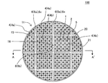
本発明の目封止ハニカム構造体の第一実施形態は、図1〜図4に示すように、複数個のハニカムセグメント4と、接合層6と、目封止部5と、を備えた、目封止ハニカム構造体100である。本実施形態の目封止ハニカム構造体100は、所謂、セグメント構造の目封止ハニカム構造体である。目封止ハニカム構造体100の外周には、複数個のハニカムセグメント4を囲繞するように配設された外周壁21を更に備えている。本実施形態の目封止ハニカム構造体100は、排ガス中に含まれる粒子状物質を除去するための捕集フィルタとして好適に利用することができる。
(1) Sealed honeycomb structure:
As shown in FIGS. 1 to 4, the first embodiment of the eye-sealing honeycomb structure of the present invention includes a plurality of
ここで、図1は、本発明の目封止ハニカム構造体の第一実施形態を模式的に示す、流入端面側からみた斜視図である。図2は、本発明の目封止ハニカム構造体の第一実施形態を模式的に示す、流入端面側からみた平面図である。図3は、図2のA−A’を模式的に示す断面図である。図4は、図2に示すハニカム構造体の接合層の構成を説明するための模式的な説明図である。 Here, FIG. 1 is a perspective view schematically showing the first embodiment of the eye-sealing honeycomb structure of the present invention when viewed from the inflow end face side. FIG. 2 is a plan view schematically showing the first embodiment of the sealing honeycomb structure of the present invention when viewed from the inflow end face side. FIG. 3 is a cross-sectional view schematically showing AA'of FIG. FIG. 4 is a schematic explanatory view for explaining the structure of the bonding layer of the honeycomb structure shown in FIG.
ハニカムセグメント4は、流入端面11から流出端面12まで延びる複数のセル2を取り囲むように配設された多孔質の隔壁1を有するものである。ハニカムセグメント4は、隔壁1の外周部分に、セグメント外周壁を更に有することにより、その全体形状が、例えば、角柱状を呈するように構成されている。なお、本発明において、セル2とは、隔壁1によって取り囲まれた空間のことを意味する。
The
目封止ハニカム構造体100は、複数個のハニカムセグメント4を備え、この複数個のハニカムセグメント4の側面同士が接合層6を介して接合されている。複数個のハニカムセグメント4のうち、目封止ハニカム構造体100の中央部分に配置されたハニカムセグメント4は、流入端面11から流出端面12に向かう方向を軸方向とする「角柱状」を呈するものとなっている。一方で、複数個のハニカムセグメント4のうち、外周壁21と接している外周部分に配置されたハニカムセグメント4は、角柱状に形成されたハニカムセグメント4の一部が、外周壁21の形状に沿って研削された柱状のものとなっている。
The sealing
接合層6は、複数個のハニカムセグメント4の側面同士を互いに接合する接合材によって構成されたものである。複数個のハニカムセグメント4が接合層6を介して接合された接合体を、以下、「ハニカムセグメント接合体20」ということがある。
The
それぞれのハニカムセグメント4におけるセル2は、流入端面11側又は流出端面12側のいずれか一方の端部が、目封止部5によって目封止されている。即ち、目封止部5は、それぞれのハニカムセグメント4の流入端面11における所定のセル2の開口部、及び流出端面12における所定のセル2以外の残余のセル2の開口部に配設されている。
In the
以下、ハニカムセグメント4の流入端面11におけるセル2の開口部に目封止部5が配設されたセル2(即ち、上述した所定のセル2)を、「流出セル」ということがある。ハニカムセグメント4の流出端面12におけるセル2の開口部に目封止部5が配設されたセル2(即ち、上述した残余のセル2)を、「流入セル」ということがある。ハニカムセグメント4のセル2の開口部に目封止部5が配設されたものを、「目封止ハニカムセグメント」ということがある。
Hereinafter, the
本実施形態の目封止ハニカム構造体100は、特に、ハニカムセグメント4を接合する接合層6の接合強度に関して、主要な特徴を有している。ここで、ハニカムセグメント接合体20を構成するハニカムセグメント4であって、外周壁21と接するように配置されたハニカムセグメント4を、「外周ハニカムセグメント4a」という。そして、外周ハニカムセグメント4a同士を接合する接合層6を、「外周接合層6a」という。外周ハニカムセグメント4a同士を接合している外周接合層6aの接合強度を、「接合強度A1」とする。また、ハニカムセグメント接合体20のセル2の延びる方向に直交する断面の重心を含む又は当該重心に最も近い位置に存在するハニカムセグメント4を、「中央ハニカムセグメント4b」という。そして、中央ハニカムセグメント4bと、当該中央ハニカムセグメント4bに隣接する他のハニカムセグメント4とを接合する接合層6を、「中央接合層6b」という。この中央接合層6bの接合強度を、「接合強度A2」とする。なお、中央ハニカムセグメント4bにおいて、「断面の重心を含むハニカムセグメント4」とは、この中央ハニカムセグメント4b中に、上記した重心が位置しているものをいう。一方、中央ハニカムセグメント4bにおいて、「断面の重心に最も近い位置に存在するハニカムセグメント4」とは、例えば、接合層6上に、上記した重心が位置している場合に、この重心から最も近い位置に存在しているものをいう。
The eye-sealing
本実施形態の目封止ハニカム構造体100は、外周接合層6aの接合強度A1が、中央接合層6bの接合強度A2よりも大であることを特徴とする。このように構成することによって、目封止ハニカム構造体100は、以下のような効果を奏するものである。即ち、ハニカムセグメント4の端面のクラック、及び外周壁21の表面の周方向に延びるクラックの発生状況を悪化させることなく、接合層6(より具体的には、外周接合層6a)に沿った外周壁21の表面でのクラックの発生を有効に抑制することができる。
The sealing
外周接合層6aの接合強度A1と、中央接合層6bの接合強度A2とが同じ場合、接合強度A1及び接合強度A2が共に小さい値であると、ハニカムセグメント接合体20の外周部分における接合層6にクラックが発生し易くなる。一方で、接合強度A1及び接合強度A2を共に大きい値とすると、再生処理の際に、PMの燃焼熱によってDPFに高い熱応力が発生した際に、接合層6での応力緩和が不十分となりハニカムセグメント4の端面でのクラックの抑制が困難になる。また、外周接合層6aの接合強度A1が、中央接合層6bの接合強度A2よりも小さくなる場合においても、ハニカムセグメント接合体20の外周部分における接合層6にクラックが発生し易くなる。
When the bonding strength A1 of the outer
ここで、本発明において、「外周接合層6aの接合強度A1」及び「中央接合層6bの接合強度A2」とは、以下の測定方法によって測定される値のことをいう。まず、「接合強度A1」を測定方法について説明する。まず、ハニカムセグメント接合体20から、測定対象となる「外周接合層6a」を含む2つの外周ハニカムセグメント4aを切り出して、接合強度A1を測定するための測定試料を作製する。この測定試料は、2つの外周ハニカムセグメント4aが外周接合層6aによって接合されたものである。この測定試料を、せん断荷重測定器を使用し、外周ハニカムセグメント4aの端面に、荷重速度が2mm/minとなるように荷重を加えていき、外周接合層6aが破壊する際の破壊荷重F1を測定する。また、2つの外周ハニカムセグメント4aを接合する外周接合層6aの接合面の面積S1を測定し、下記式(1)に基づいて、接合強度A1を算出する。なお、せん断荷重測定器での破壊荷重F1の測定においては、2つの外周ハニカムセグメント4aのうち、一方の外周ハニカムセグメント4aの下側端面のみを支持し、もう一方の外周ハニカムセグメント4aの下側端面を支持せずに、荷重を加えることとする。
式(1):接合強度A1=破壊荷重F1/接合面の面積S1
Here, in the present invention, the "bonding strength A1 of the outer
Equation (1): Joint strength A1 = breaking load F1 / joint surface area S1
次に、「接合強度A2」を測定方法について説明する。まず、ハニカムセグメント接合体20から、セル2の延びる方向に直交する断面の重心を含む又は当該重心に最も近い位置に存在する中央ハニカムセグメント4bを見つける。そして、測定対象となる「中央接合層6b」を含む中央ハニカムセグメント4bと他のハニカムセグメント4とを切り出して、接合強度A2を測定するための測定試料を作製する。この測定試料は、中央ハニカムセグメント4bと他のハニカムセグメント4とが中央接合層6bによって接合されたものである。この測定試料を、せん断荷重測定器を使用し、接合強度A1の測定と同様の方法で、中央接合層6bが破壊する際の破壊荷重F2を測定する。また、中央接合層6bの接合面の面積S2を測定し、下記式(2)に基づいて、接合強度A2を算出する。
式(2):接合強度A2=破壊荷重F2/接合面の面積S2
Next, a method for measuring "joint strength A2" will be described. First, the
Equation (2): Joint strength A2 = breaking load F2 / joint surface area S2
接合強度A1が、接合強度A2の1.2〜1.6倍であり、1.2〜1.5倍であることが好ましい。このように構成することによって、外周接合層6aに沿った外周壁21の表面でのクラックの発生をより有効に抑制することができる。
Bonding strength A1 is Ri 1.2 to 1.6 Baidea bonding strength A2, it is favorable preferable is 1.2 to 1.5 times. With such a configuration, the occurrence of cracks on the surface of the outer
外周接合層6aの接合強度A1が、850〜1200kPaであることが好ましく、900〜1150kPaであることが更に好ましく、900〜1100kPaであることが特に好ましい。接合強度A1が850kPa未満であると、接合層6におけるクラックの発生を有効に抑制するという観点からあまり好ましくない。一方、接合強度A1が1200kPaを超えると、ハニカムセグメント4の端面でのクラックを抑制するという観点からあまり好ましくない。なお、接合強度A1が上記数値範囲の場合においても、接合強度A1が、接合強度A2よりも大である。
The bonding strength A1 of the outer
中央接合層6bの接合強度A2が、400〜900kPaであることが好ましく、600〜850kPaであることが更に好ましく、700〜800kPaであることが特に好ましい。接合強度A2が400kPa未満であると、中央接合層6bによる接合を維持するという観点からあまり好ましくない。一方、接合強度A2が900kPaを超えると、ハニカムセグメント4の端面でのクラックの抑制、及びリングオフクラックの抑制という観点からあまり好ましくない。なお、接合強度A2が上記数値範囲の場合においても、接合強度A1が、接合強度A2よりも大である。
The bonding strength A2 of the
外周接合層6aの接合強度A1が、中央接合層6bの接合強度A2の1.2〜1.6倍であり、1.2〜1.5倍であることが好ましく、1.3〜1.4倍であることが特に好ましい。接合強度A1が、接合強度A2の1.2倍未満であると、外周接合層6aに沿った外周壁21の表面でのクラックの抑制という観点からあまり好ましくない。一方、接合強度A1が、接合強度A2の1.6倍を超えると、ハニカムセグメント4の端面でのクラックの抑制という観点からあまり好ましくない。
Bonding strength A1 of the
本実施形態の目封止ハニカム構造体100においては、外周接合層6aと、中央接合層6bとは、その材質が異なっていてもよい。また、外周接合層6aと、中央接合層6bとは、その気孔率等が異なることにより、互いの接合強度が異なるように構成されたものであってもよい。このように構成することによって、接合強度A1と接合強度A2との差が明確となり、これまでに説明した各効果を有効に発現させることができる。
In the mesh sealing
接合層6の材料については、特に制限はなく、従来公知のハニカム構造体における接合層の材料を用いることができる。
The material of the
本実施形態の目封止ハニカム構造体100においては、ハニカムセグメント接合体20の最外周に配置されている外周ハニカムセグメント4a同士を接合する外周接合層6aの接合強度A1が、それ以外の接合層6の接合強度よりも大であってもよい。即ち、外周接合層6aの接合強度A1のみが、それ以外の接合層6の接合強度よりも大であってもよい。ただし、接合強度A1が、接合強度A2よりも大であれば、外周接合層6a及び中央接合層6b以外の接合強度については、特に制限はない。例えば、外周ハニカムセグメント4aよりも1個又は2個以上内側のハニカムセグメント4を接合する接合層(但し、中央接合層6bを除く)の接合強度が、外周接合層6aの接合強度A1と同じであってもよい。また、外周ハニカムセグメント4aよりも1個又は2個以上内側のハニカムセグメント4を接合する接合層の接合強度が、中央接合層6bの接合強度A2と同じであってもよい。例えば、「最外周に配置されている外周ハニカムセグメント4a同士を接合する外周接合層6a」の接合強度のみが、特に高い接合強度となっている実施形態等の様々形態をとることができる。
In the sealing
これまでに説明したように、本実施形態の目封止ハニカム構造体100は、セル2の延びる方向に直交する断面において、外周接合層6aを含む接合強度が相対的に大きい外周部15と、中央接合層6bを含む接合強度が相対的に小さい中央部16と、が存在する。以下、外周部15における接合強度が相対的に大きい接合層6を、「高接合強度接合層6x」と称することがある。セル2の延びる方向に直交する断面において、接合層6が占める全面積に対する、高接合強度接合層6xが占める面積の比率が、5〜55%であることが好ましく、10〜50%であることが更に好ましく、10〜40%であることが特に好ましい。高接合強度接合層6xが占める面積の比率が、上記数値範囲を超えると、高接合強度接合層6xでのクラックの発生抑制と、ハニカムセグメント4の端面や外周壁21の表面でのクラックの発生抑制とのバランスがとり難くなることがある。
As described above, the sealing
「接合層6のセル2の延びる方向に直交する方向における幅」については特に制限はない。ここで、「接合層6のセル2の延びる方向に直交する方向における幅」とは、接合層によって接合されるハニカムセグメントの側面相互間の距離のことである。以下、「接合層6のセル2の延びる方向に直交する方向における幅」を、単に、「接合層6の幅」ということがある。接合層6の幅は、例えば、0.3〜3.0mmであることが好ましく、0.5〜2.0mmであることが特に好ましい。接合層6の幅が0.3mm未満であると、目封止ハニカム構造体100の接合強度が低下し易くなる点で好ましくない。接合層6の幅が3.0mmを超えると、目封止ハニカム構造体100の圧力損失が増大することがある点で好ましくない。
There is no particular limitation on "the width of the
ハニカムセグメント4に形成されているセル2の形状については特に制限はない。例えば、セル2の延びる方向に直交する断面における、セル2の形状としては、多角形、円形、楕円形等を挙げることができる。多角形としては、三角形、四角形、五角形、六角形、八角形等を挙げることができる。なお、セル2の形状は、三角形、四角形、五角形、六角形、八角形であることが好ましい。また、セル2の形状については、全てのセル2の形状が同一形状であってもよいし、異なる形状であってもよい。例えば、図示は省略するが、四角形のセルと、八角形のセルと混在したものであってもよい。また、セル2の大きさについては、全てのセル2の大きさが同じであってもよいし、異なっていてもよい。例えば、図示は省略するが、複数のセルのうち、一部のセルの大きさを大きくし、他のセルの大きさを相対的に小さくしてもよい。
The shape of the
隔壁1によって区画されるセル2のセル密度が、15〜90個/cm2であることが好ましく、30〜60個/cm2であることが更に好ましい。このように構成することによって、本実施形態の目封止ハニカム構造体を、自動車のエンジンから排出される排ガスを浄化するためのフィルタとして好適に利用することができる。
The cell density of the
隔壁1の気孔率が、30〜80%であることが好ましく、35〜75%であることが更に好ましく、40〜70%であることが特に好ましい。隔壁1の気孔率は、水銀圧入法によって測定された値である。隔壁1の気孔率の測定は、例えば、Micromeritics社製のオートポア9500(商品名)を用いて行うことができる。気孔率の測定は、各ハニカムセグメント4の隔壁1の一部を切り出して試験片とし、その試験片を用いて行うことができる。隔壁1の気孔率が、30%未満であると、目封止ハニカム構造体100自体の圧力損失が増大することや、触媒の担持後における圧力損失のばらつきが大きくなることがある。隔壁1の気孔率が、80%を超えると、目封止ハニカム構造体100のフィルタとしての強度、捕集性能が低下してしまうことがある。
The porosity of the
ハニカムセグメント4の形状については、特に制限はない。例えば、ハニカムセグメント4の形状として、当該ハニカムセグメント4の軸方向に直交する断面形状が四角形や六角形等の多角形の角柱状を挙げることができる。なお、目封止ハニカム構造体100の最外周に配設されるハニカムセグメント4は、目封止ハニカム構造体100の全体形状に応じて、角柱状の一部が研削等により加工されたものであってもよい。
The shape of the
目封止ハニカム構造体100の全体形状については、特に制限はない。例えば、図1に示す目封止ハニカム構造体100の全体形状は、流入端面11及び流出端面12が円形の円柱状である。その他、図示は省略するが、目封止ハニカム構造体の全体形状としては、流入端面及び流出端面が、楕円形やレーストラック(Racetrack)形や長円形等の略円形の柱状であってもよい。また、目封止ハニカム構造体の全体形状としては、流入端面及び流出端面が、四角形や六角形等の多角形の角柱状であってもよい。
The overall shape of the sealing
ハニカムセグメント4を構成する材料に特に制限はないが、強度、耐熱性、耐久性等の観点から、下記材料群から選択される少なくとも1種の材質が好ましい。材料群とは、炭化珪素、珪素−炭化珪素系複合材料、窒化珪素、コージェライト、ムライト、アルミナ、スピネル、炭化珪素−コージェライト系複合材料、リチウムアルミニウムシリケート、チタン酸アルミニウム、及びFe−Cr−Al系金属の材料群である。これらの中でも、炭化珪素、又は珪素−炭化珪素系複合材料が更に好ましい。珪素−炭化珪素系複合材料は、炭化珪素(SiC)を骨材とし、かつ珪素(Si)を結合材とする複合材料である。
The material constituting the
目封止部5の材料については特に制限はない。目封止部5の材料は、例えば、ハニカムセグメント4を構成する材料として例示した材料と同様な材料が好ましい。
There is no particular limitation on the material of the sealing portion 5. As the material of the sealing portion 5, for example, a material similar to the material exemplified as the material constituting the
目封止ハニカム構造体100の大きさ、例えば、流入端面11から流出端面12までの長さや、目封止ハニカム構造体100のセル2の延びる方向に直交する断面の大きさについては、特に制限はない。本実施形態の目封止ハニカム構造体100を、排ガス浄化用のフィルタとして用いた際に、最適な浄化性能を得るように、各大きさを適宜選択すればよい。例えば、目封止ハニカム構造体100の流入端面11から流出端面12までの長さは、150〜305mmであることが好ましく、150〜200mmであることが特に好ましい。また、目封止ハニカム構造体100のセル2の延びる方向に直交する断面の面積は、144〜330mm2であることが好ましく、144〜178mm2であることが特に好ましい。
The size of the sealing
本実施形態の目封止ハニカム構造体100においては、所定のセル2の流入端面11側の開口部、及び残余のセルの流出端面12側の開口部に、目封止部5が配設されている。ここで、流出端面12側の開口部に目封止部5が配設され、流入端面11側が開口したセル2を、流入セルとする。また、流入端面11側の開口部に目封止部5が配設され、流出端面12側が開口したセル2を、流出セルとする。流入セルと流出セルとは、隔壁1を隔てて交互に配設されていることが好ましい。そして、それによって、目封止ハニカム構造体100の両端面に、目封止部5と「セル2の開口部」とにより、市松模様が形成されていることが好ましい。
In the sealing
本実施形態の目封止ハニカム構造体100においては、複数のセル2を形成する隔壁1に触媒が担持されていてもよい。隔壁1に触媒を担持するとは、隔壁1の表面及び隔壁に形成された細孔の内壁に、触媒がコーティングされることをいう。このように構成することによって、排ガス中のCOやNOxやHCなどを触媒反応によって無害な物質にすることができる。また、捕集した煤等のPMの酸化を促進させることができる。
In the sealing
(2)目封止ハニカム構造体の製造方法:
実施形態の目封止ハニカム構造体の製造方法については、特に制限はなく、例えば、以下のような方法により製造することができる。まず、ハニカムセグメントを作製するための可塑性の坏土を調製する。ハニカムセグメントを作製するための坏土は、原料粉末として、前述のハニカムセグメントの好適な材料の中から選ばれた材料に、適宜、バインダ等の添加剤、及び水を添加することによって調製することができる。
(2) Manufacturing method of sealable honeycomb structure:
The method for producing the mesh-sealed honeycomb structure of the embodiment is not particularly limited, and for example, it can be produced by the following method. First, a plastic clay for making a honeycomb segment is prepared. The clay for producing the honeycomb segment is prepared by appropriately adding an additive such as a binder and water to a material selected from the above-mentioned suitable materials for the honeycomb segment as a raw material powder. Can be done.
次に、このようにして得られた坏土を押出成形することにより、複数のセルを取り囲むように配設された隔壁、及び最外周に配設されたセグメント外周壁を有する、角柱状のハニカム成形体を作製する。ハニカム成形体は、複数個作製する。 Next, by extruding the clay thus obtained, a prismatic honeycomb having a partition wall arranged so as to surround a plurality of cells and a segment outer peripheral wall arranged on the outermost circumference. A molded body is produced. A plurality of honeycomb molded bodies are produced.
得られたハニカム成形体を、例えば、マイクロ波及び熱風で乾燥し、ハニカム成形体の作製に用いた材料と同様の材料で、セルの開口部を目封止することで目封止部を作製する。目封止部を作製した後に、ハニカム成形体を更に乾燥してもよい。 The obtained honeycomb molded body is dried with, for example, microwaves and hot air, and the opening of the cell is sealed with the same material as the material used for producing the honeycomb molded body to prepare a mesh sealing portion. To do. After producing the mesh sealing portion, the honeycomb molded body may be further dried.
次に、目封止部を作製したハニカム成形体を焼成することにより、目封止ハニカムセグメントを得る。焼成温度及び焼成雰囲気は原料により異なり、当業者であれば、選択された材料に最適な焼成温度及び焼成雰囲気を選択することができる。 Next, the honeycomb molded body in which the sealing portion is produced is fired to obtain a sealing honeycomb segment. The firing temperature and firing atmosphere differ depending on the raw material, and a person skilled in the art can select the optimum firing temperature and firing atmosphere for the selected material.
次に、複数の目封止ハニカムセグメントを、接合材を用いて互いに接合し、乾燥硬化させた後、所望の形状となるよう外周を加工することによって、セグメント構造の目封止ハニカム構造体を得ることができる。接合材としては、セラミックス材料に、水等の溶媒を加えてペースト状又はスラリー状にしたものを用いることができる。この際、接合材としては、以下のように、2種類の接合材を作製することが好ましい、例えば、接合材に添加する水等の溶媒の量を調節し、溶媒含有比の異なる接合材を2種類作製する。また、接合材に対して、異なる量の造孔材を添加し、造孔材含有比の異なる接合材を2種類作製する。溶媒の量を少なくすると、接合材によって形成される接合層の接合強度が高くなる。また、造孔材の量を少なくすると、接合材によって形成される接合層の接合強度が高くなる。 Next, a plurality of sealing honeycomb segments are joined to each other using a bonding material, dried and cured, and then the outer circumference is processed so as to have a desired shape to obtain a sealing honeycomb structure having a segment structure. Obtainable. As the bonding material, a ceramic material to which a solvent such as water is added to form a paste or a slurry can be used. At this time, as the bonding material, it is preferable to prepare two types of bonding materials as follows. For example, the amount of solvent such as water added to the bonding material is adjusted, and bonding materials having different solvent content ratios are used. Make two types. Further, different amounts of the pore-forming material are added to the bonding material to prepare two types of bonding materials having different pore-forming material content ratios. When the amount of the solvent is reduced, the bonding strength of the bonding layer formed by the bonding material is increased. Further, when the amount of the pore-forming material is reduced, the bonding strength of the bonding layer formed by the bonding material is increased.
上記のように作製した2種類の接合層を、最外周に配置される目封止ハニカムセグメント同士を接合する部分と、それ以外の部分とで、それぞれ使い分けることで、得られる目封止ハニカム構造体において、外周部と中央部とで、接合層の接合強度を変えることができる。 A mesh-sealing honeycomb structure obtained by properly using the two types of bonding layers produced as described above in a portion for joining the sealing honeycomb segments arranged on the outermost circumference and a portion other than the bonding layer. In the body, the bonding strength of the bonding layer can be changed between the outer peripheral portion and the central portion.
また、目封止ハニカムセグメントの接合体の外周を加工した後の加工面は、セルが露出した状態となっているため、接合体の加工面に外周コート材を塗工して、外周壁を形成してもよい。外周コート材の材料としては、例えば、無機繊維、コロイダルシリカ、粘土、セラミック粒子等の無機原料に、有機バインダ、発泡樹脂、分散剤等の添加剤と水とを加えて混練し、スラリー状としたものを挙げることができる。 Further, since the cells are exposed on the processed surface after processing the outer periphery of the joint body of the sealing honeycomb segment, the outer peripheral coating material is applied to the processed surface of the joint body to form the outer peripheral wall. It may be formed. As a material for the outer peripheral coating material, for example, an inorganic raw material such as inorganic fiber, colloidal silica, clay, or ceramic particles is kneaded with an additive such as an organic binder, a foamed resin, or a dispersant and water to form a slurry. Can be mentioned.
以下、本発明を実施例によって更に具体的に説明するが、本発明はこれらの実施例によって何ら限定されるものではない。 Hereinafter, the present invention will be described in more detail with reference to Examples, but the present invention is not limited to these Examples.
(実施例1)
セラミックス原料として、炭化珪素(SiC)粉末と金属珪素(Si)粉末とを80:20の質量割合で混合した混合原料を準備した。この混合原料に、バインダとしてヒドロキシプロピルメチルセルロース、造孔材として吸水性樹脂を添加するとともに、水を添加して成形原料を作製した。得られた成形原料を、ニーダー(kneader)を用いて混練し、坏土を得た。
(Example 1)
As a ceramic raw material, a mixed raw material in which silicon carbide (SiC) powder and metallic silicon (Si) powder were mixed at a mass ratio of 80:20 was prepared. To this mixed raw material, hydroxypropyl methylcellulose as a binder and a water-absorbent resin as a pore-forming material were added, and water was added to prepare a molding raw material. The obtained molding raw material was kneaded using a kneader to obtain a clay.
次に、得られた坏土を、真空押出成形機を用いて成形し、四角柱状のハニカム成形体を25個作製した。この四角柱状のハニカム成形体の1個ずつが、ハニカムセグメントとなる。 Next, the obtained clay was molded using a vacuum extrusion molding machine to prepare 25 square columnar honeycomb molded bodies. Each of the square columnar honeycomb molded bodies becomes a honeycomb segment.
次に、得られたハニカム成形体を高周波誘電加熱乾燥した後、熱風乾燥機を用いて120℃で2時間乾燥した。 Next, the obtained honeycomb molded product was dried by high-frequency dielectric heating and then dried at 120 ° C. for 2 hours using a hot air dryer.
次に、乾燥後のハニカム成形体に、目封止部を形成した。まず、乾燥後のハニカム成形体の流入端面にマスクを施した。次に、マスクの施された端部(流入端面側の端部)を目封止スラリーに浸漬し、マスクが施されていないセル(流出セル)の開口部に目封止スラリーを充填した。このようにして、乾燥後のハニカム成形体の流入端面側に、目封止部を形成した。そして、乾燥後のハニカム成形体の流出端面についても同様にして、流入セルにも目封止部を形成した。 Next, a mesh sealing portion was formed on the dried honeycomb molded body. First, a mask was applied to the inflow end face of the dried honeycomb molded body. Next, the masked end (the end on the inflow end face side) was immersed in the sealing slurry, and the opening of the unmasked cell (outflow cell) was filled with the sealing slurry. In this way, a mesh sealing portion was formed on the inflow end face side of the dried honeycomb molded body. Then, in the same manner for the outflow end face of the dried honeycomb molded body, a mesh sealing portion was formed in the inflow cell.
そして、目封止部の形成されたハニカム成形体を脱脂し、焼成し、目封止ハニカムセグメントを得た。脱脂の条件は、550℃で3時間とし、焼成の条件は、アルゴン雰囲気下で、1450℃、2時間とした。 Then, the honeycomb molded body on which the sealing portion was formed was degreased and fired to obtain a sealing honeycomb segment. The degreasing conditions were 550 ° C. for 3 hours, and the firing conditions were 1450 ° C. for 2 hours under an argon atmosphere.
以上のようにして、実施例1の目封止ハニカム構造体の製造に使用する目封止ハニカムセグメントを作製した。作製した目封止ハニカムセグメントは、軸方向に直交する断面が正方形で、その正方形の一辺の長さ(セグメントサイズ)が36.5mmであった。結果を、表1の「ハニカムセグメント」の「一辺の長さ(mm)」の欄に示す。また、目封止ハニカムセグメントは、その軸方向の長さが178mmであった。 As described above, the eye-sealing honeycomb segment used for manufacturing the eye-sealing honeycomb structure of Example 1 was produced. The prepared eye-sealing honeycomb segment had a square cross section orthogonal to the axial direction, and the length of one side (segment size) of the square was 36.5 mm. The results are shown in the "One side length (mm)" column of the "Honeycomb segment" in Table 1. The length of the sealing honeycomb segment in the axial direction was 178 mm.
目封止ハニカムセグメントは、隔壁の厚さが0.3mmで、セル密度が46個/cm2であった。また、隔壁の気孔率は、41%であった。隔壁の気孔率は、Micromeritics社製のオートポア9500(商品名)によって測定した。 The sealable honeycomb segment had a partition wall thickness of 0.3 mm and a cell density of 46 cells / cm 2 . The porosity of the partition wall was 41%. The porosity of the partition wall was measured by Autopore 9500 (trade name) manufactured by Micromeritics.
次に、目封止ハニカムセグメントを接合するための接合材を、2種類作製した。即ち、目封止ハニカム構造体における接合層を形成するための材料が、上記接合材である。以下、2種類の接合材を、「接合材A」及び「接合材B」とする。接合材Aは、その接合強度が900kPaとなるように調製した。接合材Bは、その接合強度が700kPaとなるように調製した。 Next, two types of joining materials for joining the sealing honeycomb segments were prepared. That is, the material for forming the bonding layer in the sealing honeycomb structure is the bonding material. Hereinafter, the two types of joining materials will be referred to as "joining material A" and "joining material B". The bonding material A was prepared so that the bonding strength was 900 kPa. The bonding material B was prepared so that the bonding strength was 700 kPa.
次に、得られた目封止ハニカムセグメントを、互いの側面同士が対向するように隣接して配置された状態で、接合材によって接合し、700℃にて熱処理を行って、ハニカムセグメント接合体を作製した。ハニカムセグメント接合体は、その端面において、縦方向に5個、横方向に5個の合計25個のハニカムセグメントが配列するように接合して作製した。表1の「ハニカムセグメント」における「個数(個)」及び「配置(個×個)」の欄には、各実施例に用いたハニカムセグメントの個数、及びその配置を示す。例えば、「配置(個数×個数)」の欄に、「5×5」と記載されている場合には、縦方向に5個、横方向に5個の合計25個のハニカムセグメントを用いたことを意味する。 Next, the obtained eye-sealing honeycomb segments are joined with a bonding material in a state where the side surfaces of the obtained honeycomb segments are adjacent to each other so as to face each other, and heat treatment is performed at 700 ° C. to form a honeycomb segment bonded body. Was produced. The honeycomb segment joint body was produced by joining so that a total of 25 honeycomb segments, 5 in the vertical direction and 5 in the horizontal direction, were arranged on the end face thereof. The columns of "number (pieces)" and "arrangement ( pieces x pieces )" in "honeycomb segments" in Table 1 indicate the number of honeycomb segments used in each embodiment and their arrangement. For example, when "5 x 5" is described in the "arrangement (number x number)" column, a total of 25 honeycomb segments of 5 in the vertical direction and 5 in the horizontal direction were used. Means.
実施例1においては、ハニカムセグメント接合体の最外周に位置する12個の目封止ハニカムセグメント同士を接合する際に、上記した「接合材A」を使用した。また、それ以外の接合部分については、上記した「接合材B」を使用した。接合材によって形成された接合層の厚さは、1.0mmであった。接合材Aを使用した部分を、ハニカムセグメント接合体の外周部とする。また、接合材Bを使用した部分を、ハニカムセグメント接合体の中央部とする。 In Example 1, the above-mentioned "bonding material A" was used when joining the twelve eye-sealing honeycomb segments located on the outermost periphery of the honeycomb segment joint body. Further, for the other joint portions, the above-mentioned "joining material B" was used. The thickness of the bonding layer formed by the bonding material was 1.0 mm. The portion using the bonding material A is defined as the outer peripheral portion of the honeycomb segment bonded body. Further, the portion using the bonding material B is designated as the central portion of the honeycomb segment bonded body.
次に、ハニカムセグメント接合体の外周を円柱状に研削加工し、その外周面にコート材を塗布して、実施例1の目封止ハニカム構造体を得た。実施例1の目封止ハニカム構造体は、端面の直径が191mmであった。 Next, the outer periphery of the honeycomb segment joint body was ground into a columnar shape, and a coating material was applied to the outer peripheral surface thereof to obtain a mesh-sealed honeycomb structure of Example 1. The mesh-sealed honeycomb structure of Example 1 had an end face diameter of 191 mm.
実施例1の目封止ハニカム構造体について、外周部における接合層の接合強度と、中央部における接合層の接合強度とを、以下の方法で測定した。結果を、表2の「外周部における接合強度(kPa)」、及び「中央部における接合強度(kPa)」の欄に示す。また、表2の「接合強度比率(外周部/中央部)」の欄に、中央部における接合強度に対する、外周部における接合強度の比率を示す。また、表2の「接合面積比率(高接合強度面積/総接合面積)」の欄に、接合層の総接合面積に対する、高接合強度接合層の接合面積の比率を示す。なお、高接合強度接合層とは、外周部における接合強度が相対的に大きい接合層のことを意味する。また、高接合強度面積とは、高接合強度接合層によって接合されている接合面の面積のことを意味する。 With respect to the mesh-sealed honeycomb structure of Example 1, the bonding strength of the bonding layer at the outer peripheral portion and the bonding strength of the bonding layer at the central portion were measured by the following methods. The results are shown in the columns of "Joint strength at the outer peripheral portion (kPa)" and "Joint strength at the central portion (kPa)" in Table 2. Further, in the column of "Joint strength ratio (outer peripheral portion / central portion)" in Table 2, the ratio of the joint strength in the outer peripheral portion to the joint strength in the central portion is shown. Further, in the column of "Joining area ratio (high bonding strength area / total bonding area)" in Table 2, the ratio of the bonding area of the high bonding strength bonding layer to the total bonding area of the bonding layer is shown. The high bonding strength bonding layer means a bonding layer having a relatively high bonding strength at the outer peripheral portion. Further, the high bonding strength area means the area of the bonding surface bonded by the high bonding strength bonding layer.
(接合強度の測定方法)
まず、外周接合層を含む2つの外周ハニカムセグメントを切り出して、外周部における接合強度(即ち、接合強度A1)を測定するための測定試料を作製した。作製した測定試料を、せん断荷重測定器を使用し、外周ハニカムセグメントの端面に、荷重速度が2mm/minとなるように荷重を加えていき、外周接合層が破壊する際の破壊荷重F1を測定した。また、2つの外周ハニカムセグメントを接合する外周接合層の接合面の面積S1を測定し、上記式(1)に基づいて、接合強度A1としての「外周部における接合強度(kPa)」を求めた。また、中央接合層を含む中央ハニカムセグメントと他のハニカムセグメントとを切り出して、中央部における接合強度(即ち、接合強度A2)を測定するための測定試料を作製した。作製した測定試料を、せん断荷重測定器を使用し、上記と同様の方法で、中央接合層が破壊する際の破壊荷重F2を測定した。また、中央接合層の接合面の面積S2を測定し、上記式(2)に基づいて、接合強度A2としての「中央部における接合強度(kPa)」を求めた。
(Measurement method of joint strength)
First, two outer peripheral honeycomb segments including the outer peripheral bonding layer were cut out to prepare a measurement sample for measuring the bonding strength (that is, bonding strength A1) at the outer peripheral portion. Using a shear load measuring device, a load is applied to the end face of the outer peripheral honeycomb segment so that the load velocity is 2 mm / min, and the fracture load F1 when the outer peripheral joint layer breaks is measured. did. Further, the area S1 of the joint surface of the outer peripheral bonding layer for joining the two outer peripheral honeycomb segments was measured, and the "bonding strength (kPa) at the outer peripheral portion" as the bonding strength A1 was obtained based on the above formula (1). .. Further, the central honeycomb segment including the central bonding layer and the other honeycomb segments were cut out to prepare a measurement sample for measuring the bonding strength (that is, bonding strength A2) in the central portion. Using a shear load measuring device, the prepared measurement sample was measured for a fracture load F2 when the central bonding layer was fractured by the same method as described above. Further, the area S2 of the joint surface of the central joint layer was measured, and the "joint strength (kPa) at the central portion" as the joint strength A2 was obtained based on the above formula (2).

また、実施例1の目封止ハニカム構造体について、以下の方法で、「急速冷却試験(電気炉スポーリング試験:E−sp評価)」、及び「クラック限界評価」を行った。結果を表3に示す。 In addition, the "rapid cooling test (electric furnace spalling test: E-sp evaluation)" and "crack limit evaluation" were performed on the sealing honeycomb structure of Example 1 by the following methods. The results are shown in Table 3.
[急速冷却試験(電気炉スポーリング試験:E−sp評価)]
目封止ハニカム構造体を、炉内の温度が200℃の電気炉に入れて2時間加熱し、目封止ハニカム構造体の均一な温度にした。その後、加熱した目封止ハニカム構造体を電気炉から取り出し、室温まで急速に冷却する。急速冷却後の目封止ハニカム構造体について、外周壁におけるクラックの発生を確認する。外周壁にクラックが発生していない場合には、炉内の温度を25℃ずつ上昇させて、外周壁にクラックが発生するまで、上記した加熱と急速冷却とを繰り返し行う。外周壁にクラックが発生した炉内温度よりも1回前の操作の炉内温度を、急速冷却試験における測定値とする。
[Rapid cooling test (electric furnace spalling test: E-sp evaluation)]
The sealing honeycomb structure was placed in an electric furnace having a temperature of 200 ° C. and heated for 2 hours to bring the sealing honeycomb structure to a uniform temperature. Then, the heated eye-sealing honeycomb structure is taken out from the electric furnace and rapidly cooled to room temperature. Confirm the occurrence of cracks on the outer peripheral wall of the sealing honeycomb structure after rapid cooling. When no cracks are generated on the outer peripheral wall, the temperature inside the furnace is raised by 25 ° C., and the above heating and rapid cooling are repeated until cracks are generated on the outer peripheral wall. The temperature inside the furnace, which is operated one time before the temperature inside the furnace where the outer wall is cracked, is used as the measured value in the rapid cooling test.
[クラック限界評価]
目封止ハニカム構造体を、ディーゼルエンジンの排気系に搭載し、この目封止ハニカム構造体にススを堆積させた。次いで、排ガス温度を2℃/秒で650℃まで上昇させた。その後、アイドリング運転に条件を変更して、ガス流量を急激に減らした。このような条件で目封止ハニカム構造体内に堆積したススを燃焼させ、目封止ハニカム構造体の再生を行なった。目封止ハニカム構造体内のススの堆積割合を次第に増加させて、上記した試験(目封止ハニカム構造体の再生)を繰り返し行った。なお、ススの堆積割合とは、目封止ハニカム構造体の単位容積あたり(1Lあたり)の、目封止ハニカム構造体内に堆積したススの質量(g)の割合である。そして、目封止ハニカム構造体にクラックが発生しない最大のススの堆積割合を調査した。このときのススの堆積割合を「クラック限界」とする。クラック限界が、6g/L未満である場合を「B」とした。6g/L以上である場合を「A」とした。
[Crack limit evaluation]
The sealing honeycomb structure was mounted on the exhaust system of the diesel engine, and soot was deposited on the sealing honeycomb structure. The exhaust gas temperature was then raised to 650 ° C at 2 ° C / sec. After that, the conditions were changed to idling operation, and the gas flow rate was drastically reduced. Under such conditions, the soot accumulated in the sealing honeycomb structure was burned to regenerate the sealing honeycomb structure. The above-mentioned test (regeneration of the eye-sealing honeycomb structure) was repeated by gradually increasing the soot deposition ratio in the eye-sealing honeycomb structure. The soot deposition ratio is the ratio of the mass (g) of soot deposited in the sealing honeycomb structure per unit volume (per 1L) of the sealing honeycomb structure. Then, the maximum soot deposition ratio at which cracks did not occur in the sealing honeycomb structure was investigated. The soot deposition ratio at this time is defined as the "crack limit". The case where the crack limit was less than 6 g / L was defined as "B". The case of 6 g / L or more was designated as "A".
(実施例2,3)
表2に示すような接合強度となるように調製した接合材を使用したこと以外は、実施例1と同様の方法で、目封止ハニカム構造体を製造した。
(Examples 2 and 3)
A seal-sealing honeycomb structure was produced in the same manner as in Example 1 except that a bonding material prepared to have a bonding strength as shown in Table 2 was used.
(実施例4〜6)
ハニカムセグメント、及びハニカム接合体の構成を表1に示すように変更し、また、表2に示すような接合強度となるように調製した接合材を使用したこと以外は、実施例1と同様の方法で、目封止ハニカム構造体を製造した。
(Examples 4 to 6)
The same as in Example 1 except that the configurations of the honeycomb segment and the honeycomb joint body were changed as shown in Table 1 and the joint material prepared to have the joint strength as shown in Table 2 was used. By the method, a mesh-sealed honeycomb structure was produced.
(比較例1〜3)
ハニカムセグメント接合体を作製する際に接合材として、1種類の接合材を用いて、目封止ハニカム構造体を製造したこと以外は、実施例1と同様の方法で、目封止ハニカム構造体を製造した。
(Comparative Examples 1 to 3)
The eye-sealing honeycomb structure is produced by the same method as in Example 1 except that the eye-sealing honeycomb structure is produced by using one kind of bonding material as the bonding material when producing the honeycomb segment joint body. Manufactured.
実施例2〜6及び比較例1〜3の目封止ハニカム構造体についても、実施例1と同様の方法で、「急速冷却試験(電気炉スポーリング試験:E−sp評価)」を行った。結果を表3に示す。 The sealing honeycomb structures of Examples 2 to 6 and Comparative Examples 1 to 3 were also subjected to a "rapid cooling test (electric furnace spalling test: E-sp evaluation)" in the same manner as in Example 1. .. The results are shown in Table 3.
(結果)
実施例1〜3の目封止ハニカム構造体は、比較例1の目封止ハニカム構造体に比して、急速冷却試験において良好な結果を得ることができた。また、比較例2の目封止ハニカム構造体は、接合層の接合強度が外周部と中央部の双方において高く、急速冷却試験において良好な結果を得ることができたが、クラック限界評価において、クラック限界が6g/L未満となってしまった。また、実施例4〜6の目封止ハニカム構造体は、比較例3の目封止ハニカム構造体に比して、急速冷却試験において良好な結果を得ることができた。
(result)
The eye-sealing honeycomb structures of Examples 1 to 3 were able to obtain better results in the rapid cooling test than the eye-sealing honeycomb structures of Comparative Example 1. Further, in the mesh-sealed honeycomb structure of Comparative Example 2, the bonding strength of the bonding layer was high in both the outer peripheral portion and the central portion, and good results could be obtained in the rapid cooling test, but in the crack limit evaluation, The crack limit has become less than 6 g / L. Further, the eye-sealing honeycomb structures of Examples 4 to 6 were able to obtain better results in the rapid cooling test than the eye-sealing honeycomb structures of Comparative Example 3.
本発明の目封止ハニカム構造体は、直噴ガソリンエンジンやディーゼルエンジン等から排出される排ガスに含まれる微粒子等を除去するための捕集フィルタとして利用することができる。 The sealing honeycomb structure of the present invention can be used as a collection filter for removing fine particles and the like contained in exhaust gas discharged from a direct injection gasoline engine, a diesel engine and the like.
1:隔壁、2:セル、4:ハニカムセグメント、4a:外周ハニカムセグメント、4b:中央ハニカムセグメント、5:目封止部、6:接合層、6a:外周接合層、6b:中央接合層、6x:高接合強度接合層、11:流入端面、12:流出端面、15:外周部、16:中央部、20:ハニカムセグメント接合体、21:外周壁、100:目封止ハニカム構造体。 1: Partition, 2: Cell, 4: Honeycomb segment, 4a: Outer honeycomb segment, 4b: Central honeycomb segment, 5: Sealing part, 6: Bonding layer, 6a: Outer peripheral bonding layer, 6b: Central bonding layer, 6x : High joint strength joint layer, 11: Inflow end face, 12: Outflow end face, 15: Outer peripheral part, 16: Central part, 20: Honeycomb segment joint, 21: Outer wall, 100: Sealed honeycomb structure.
Claims (2)
複数個の前記ハニカムセグメントの側面同士を互いに接合する接合層と、
複数個の前記ハニカムセグメントが接合されたハニカムセグメント接合体の外周を囲繞するように配設された外周壁と、を備え、
前記ハニカムセグメントが、流入端面から流出端面まで延びる複数のセルを取り囲むように配設された多孔質の隔壁を有し、
それぞれの前記ハニカムセグメントにおける前記セルは、前記流入端面側又は前記流出端面側のいずれか一方の端部が、目封止部によって目封止されており、
前記接合層において、前記外周壁と接するように配置された前記ハニカムセグメント同士を接合する前記接合層を外周接合層とし、前記ハニカムセグメント接合体の前記セルの延びる方向に直交する断面の重心を含む又は当該重心に最も近い位置に存在する前記ハニカムセグメントと、当該ハニカムセグメントに隣接する他の前記ハニカムセグメントとを接合する前記接合層を中央接合層とし、前記外周接合層の接合強度A1は、前記中央接合層の接合強度A2よりも大であり、前記外周接合層の前記接合強度A1が、前記中央接合層の前記接合強度A2の1.2〜1.6倍である、目封止ハニカム構造体。 With multiple prismatic honeycomb segments,
A bonding layer that joins the side surfaces of the plurality of honeycomb segments to each other,
An outer peripheral wall arranged so as to surround the outer periphery of the honeycomb segment joint body to which the plurality of the honeycomb segments are joined is provided.
The honeycomb segment has a porous partition wall arranged so as to surround a plurality of cells extending from the inflow end face to the outflow end face.
In each of the honeycomb segments, either the inflow end face side or the outflow end face side of the cell is eye-sealed by the eye-sealing portion.
In the bonding layer, the bonding layer that joins the honeycomb segments arranged so as to be in contact with the outer peripheral wall is used as the outer peripheral bonding layer, and includes the center of gravity of the cross section orthogonal to the extending direction of the cell of the honeycomb segment bonding body. Alternatively, the bonding layer that joins the honeycomb segment existing at the position closest to the center of gravity and the other honeycomb segment adjacent to the honeycomb segment is used as the central bonding layer, and the bonding strength A1 of the outer peripheral bonding layer is the said. Ri Ah large than the bonding strength A2 of the middle bonding layer, the bonding strength A1 of the outer peripheral bonding layer, Ru 1.2 to 1.6 Baidea of the bonding strength A2 of the middle bonding layer, plugging Honeycomb structure.
Priority Applications (4)
| Application Number | Priority Date | Filing Date | Title |
|---|---|---|---|
| JP2017054567A JP6847724B2 (en) | 2017-03-21 | 2017-03-21 | Sealed honeycomb structure |
| US15/907,618 US11027269B2 (en) | 2017-03-21 | 2018-02-28 | Plugged honeycomb structure |
| CN201810170453.7A CN108625932B (en) | 2017-03-21 | 2018-03-01 | Sealed honeycomb structure |
| DE102018203504.0A DE102018203504A1 (en) | 2017-03-21 | 2018-03-08 | Locked honeycomb structure |
Applications Claiming Priority (1)
| Application Number | Priority Date | Filing Date | Title |
|---|---|---|---|
| JP2017054567A JP6847724B2 (en) | 2017-03-21 | 2017-03-21 | Sealed honeycomb structure |
Publications (3)
| Publication Number | Publication Date |
|---|---|
| JP2018153783A JP2018153783A (en) | 2018-10-04 |
| JP2018153783A5 JP2018153783A5 (en) | 2020-02-13 |
| JP6847724B2 true JP6847724B2 (en) | 2021-03-24 |
Family
ID=63450690
Family Applications (1)
| Application Number | Title | Priority Date | Filing Date |
|---|---|---|---|
| JP2017054567A Active JP6847724B2 (en) | 2017-03-21 | 2017-03-21 | Sealed honeycomb structure |
Country Status (4)
| Country | Link |
|---|---|
| US (1) | US11027269B2 (en) |
| JP (1) | JP6847724B2 (en) |
| CN (1) | CN108625932B (en) |
| DE (1) | DE102018203504A1 (en) |
Families Citing this family (6)
| Publication number | Priority date | Publication date | Assignee | Title |
|---|---|---|---|---|
| JP7037985B2 (en) * | 2018-03-30 | 2022-03-17 | 日本碍子株式会社 | Honeycomb filter |
| JP7189824B2 (en) * | 2019-03-29 | 2022-12-14 | 日本碍子株式会社 | HONEYCOMB STRUCTURE AND METHOD FOR MANUFACTURING HONEYCOMB STRUCTURE |
| WO2021049095A1 (en) * | 2019-09-11 | 2021-03-18 | 日本碍子株式会社 | Honeycomb structure and exhaust gas purification device |
| KR20210087153A (en) | 2020-01-02 | 2021-07-12 | 엘지전자 주식회사 | Storage system for an house entrance |
| CN115103716B (en) * | 2020-02-20 | 2023-07-14 | 日本碍子株式会社 | Honeycomb structure |
| JP7438327B2 (en) * | 2020-03-19 | 2024-02-26 | 日本碍子株式会社 | Honeycomb structure, exhaust gas purification catalyst and exhaust gas purification system |
Family Cites Families (14)
| Publication number | Priority date | Publication date | Assignee | Title |
|---|---|---|---|---|
| JP2003340224A (en) | 2002-05-30 | 2003-12-02 | Ngk Insulators Ltd | Honeycomb structure and manufacturing method therefor |
| FR2864576B1 (en) * | 2003-12-24 | 2006-03-03 | Saint Gobain Ct Recherches | BLOCK FOR FILTRATION OF PARTICLES CONTAINED IN THE EXHAUST GASES OF AN INTERNAL COMBUSTION ENGINE |
| FR2864575B1 (en) * | 2003-12-24 | 2006-02-10 | Saint Gobain Ct Recherches | BLOCK FOR FILTRATION OF PARTICLES CONTAINED IN THE EXHAUST GASES OF AN INTERNAL COMBUSTION ENGINE |
| KR100818476B1 (en) * | 2004-03-23 | 2008-04-02 | 니뽄 가이시 가부시키가이샤 | Honeycomb structure and method for manufacturing the same |
| WO2007119407A1 (en) | 2006-03-17 | 2007-10-25 | Ngk Insulators, Ltd. | Honeycomb structure and bonding material to be used for same |
| WO2008126333A1 (en) * | 2007-03-30 | 2008-10-23 | Ibiden Co., Ltd. | Honeycomb structure |
| JP4873326B2 (en) * | 2007-03-30 | 2012-02-08 | イビデン株式会社 | Honeycomb structure |
| US7806956B2 (en) * | 2007-08-09 | 2010-10-05 | Cummins Filtration Ip, Inc. | Tuning particulate filter performance through selective plugging and use of multiple particulate filters to reduce emissions and improve thermal robustness |
| WO2009101691A1 (en) * | 2008-02-14 | 2009-08-20 | Ibiden Co., Ltd. | Honeycomb structure |
| WO2009141891A1 (en) * | 2008-05-20 | 2009-11-26 | イビデン株式会社 | Honeycomb structure |
| JP5600245B2 (en) * | 2009-03-30 | 2014-10-01 | 日本碍子株式会社 | Honeycomb segment assembly |
| JP5844672B2 (en) | 2012-03-28 | 2016-01-20 | 日本碍子株式会社 | Honeycomb structure |
| JP6077484B2 (en) * | 2014-03-26 | 2017-02-08 | 日本碍子株式会社 | Honeycomb structure |
| JP2017054567A (en) | 2015-09-10 | 2017-03-16 | 株式会社東芝 | Semiconductor storage device |
-
2017
- 2017-03-21 JP JP2017054567A patent/JP6847724B2/en active Active
-
2018
- 2018-02-28 US US15/907,618 patent/US11027269B2/en active Active
- 2018-03-01 CN CN201810170453.7A patent/CN108625932B/en active Active
- 2018-03-08 DE DE102018203504.0A patent/DE102018203504A1/en active Granted
Also Published As
| Publication number | Publication date |
|---|---|
| CN108625932B (en) | 2021-08-31 |
| JP2018153783A (en) | 2018-10-04 |
| US20180272328A1 (en) | 2018-09-27 |
| DE102018203504A1 (en) | 2018-09-27 |
| CN108625932A (en) | 2018-10-09 |
| US11027269B2 (en) | 2021-06-08 |
Similar Documents
| Publication | Publication Date | Title |
|---|---|---|
| JP6847724B2 (en) | Sealed honeycomb structure | |
| JP4157304B2 (en) | Honeycomb structure | |
| JP5805039B2 (en) | Honeycomb structure | |
| JP6092841B2 (en) | Honeycomb filter for dust collection | |
| JP6715189B2 (en) | Honeycomb structure | |
| JP5188433B2 (en) | Honeycomb filter | |
| JP6506993B2 (en) | Honeycomb filter | |
| CN110307060B (en) | Honeycomb structure | |
| US10765986B2 (en) | Plugged honeycomb structure | |
| JP2014069123A (en) | Honeycomb filter | |
| US10857499B2 (en) | Plugged honeycomb structure | |
| JP7002377B2 (en) | Honeycomb structure | |
| JP6862245B2 (en) | Honeycomb filter | |
| JP2018167200A (en) | Honeycomb filter | |
| JP6829979B2 (en) | Sealed honeycomb structure | |
| US20100239811A1 (en) | Honeycomb structure | |
| JP6802102B2 (en) | Sealed honeycomb structure | |
| JP7057691B2 (en) | Honeycomb structure | |
| JP7202236B2 (en) | honeycomb filter | |
| JP7120876B2 (en) | honeycomb structure | |
| JP2020159337A (en) | Honeycomb structure | |
| EP2233452A1 (en) | Honeycomb structure | |
| JP2020163286A (en) | Honeycomb filter |
Legal Events
| Date | Code | Title | Description |
|---|---|---|---|
| A621 | Written request for application examination |
Free format text: JAPANESE INTERMEDIATE CODE: A621 Effective date: 20191023 |
|
| A521 | Request for written amendment filed |
Free format text: JAPANESE INTERMEDIATE CODE: A523 Effective date: 20191224 |
|
| A977 | Report on retrieval |
Free format text: JAPANESE INTERMEDIATE CODE: A971007 Effective date: 20201105 |
|
| A131 | Notification of reasons for refusal |
Free format text: JAPANESE INTERMEDIATE CODE: A131 Effective date: 20201201 |
|
| A521 | Request for written amendment filed |
Free format text: JAPANESE INTERMEDIATE CODE: A523 Effective date: 20201225 |
|
| TRDD | Decision of grant or rejection written | ||
| A01 | Written decision to grant a patent or to grant a registration (utility model) |
Free format text: JAPANESE INTERMEDIATE CODE: A01 Effective date: 20210216 |
|
| A61 | First payment of annual fees (during grant procedure) |
Free format text: JAPANESE INTERMEDIATE CODE: A61 Effective date: 20210303 |
|
| R150 | Certificate of patent or registration of utility model |
Ref document number: 6847724 Country of ref document: JP Free format text: JAPANESE INTERMEDIATE CODE: R150 |