EP1728533B1 - Medical device - Google Patents
Medical device Download PDFInfo
- Publication number
- EP1728533B1 EP1728533B1 EP06009378A EP06009378A EP1728533B1 EP 1728533 B1 EP1728533 B1 EP 1728533B1 EP 06009378 A EP06009378 A EP 06009378A EP 06009378 A EP06009378 A EP 06009378A EP 1728533 B1 EP1728533 B1 EP 1728533B1
- Authority
- EP
- European Patent Office
- Prior art keywords
- modules
- batteries
- selectively
- control
- battery
- Prior art date
- Legal status (The legal status is an assumption and is not a legal conclusion. Google has not performed a legal analysis and makes no representation as to the accuracy of the status listed.)
- Ceased
Links
- 238000009826 distribution Methods 0.000 claims description 26
- 230000000670 limiting effect Effects 0.000 claims description 19
- 230000005540 biological transmission Effects 0.000 claims description 3
- 238000010586 diagram Methods 0.000 description 25
- 238000006243 chemical reaction Methods 0.000 description 11
- 239000004020 conductor Substances 0.000 description 9
- 230000002093 peripheral effect Effects 0.000 description 7
- 238000012545 processing Methods 0.000 description 7
- 230000007423 decrease Effects 0.000 description 5
- 238000000034 method Methods 0.000 description 5
- 239000004065 semiconductor Substances 0.000 description 5
- 210000005242 cardiac chamber Anatomy 0.000 description 4
- 230000001965 increasing effect Effects 0.000 description 4
- 229910052751 metal Inorganic materials 0.000 description 4
- 239000002184 metal Substances 0.000 description 4
- 239000003351 stiffener Substances 0.000 description 4
- 238000013459 approach Methods 0.000 description 3
- 230000009977 dual effect Effects 0.000 description 3
- 230000006870 function Effects 0.000 description 3
- 230000008569 process Effects 0.000 description 3
- 230000003044 adaptive effect Effects 0.000 description 2
- 230000008602 contraction Effects 0.000 description 2
- 230000000694 effects Effects 0.000 description 2
- 238000007726 management method Methods 0.000 description 2
- 238000004519 manufacturing process Methods 0.000 description 2
- 238000012544 monitoring process Methods 0.000 description 2
- 230000037361 pathway Effects 0.000 description 2
- 230000002829 reductive effect Effects 0.000 description 2
- 230000002441 reversible effect Effects 0.000 description 2
- 210000005245 right atrium Anatomy 0.000 description 2
- 210000005241 right ventricle Anatomy 0.000 description 2
- 238000003860 storage Methods 0.000 description 2
- 238000012360 testing method Methods 0.000 description 2
- WHXSMMKQMYFTQS-UHFFFAOYSA-N Lithium Chemical compound [Li] WHXSMMKQMYFTQS-UHFFFAOYSA-N 0.000 description 1
- 241000282320 Panthera leo Species 0.000 description 1
- 239000008186 active pharmaceutical agent Substances 0.000 description 1
- 230000008901 benefit Effects 0.000 description 1
- 239000008280 blood Substances 0.000 description 1
- 210000004369 blood Anatomy 0.000 description 1
- 230000017531 blood circulation Effects 0.000 description 1
- 230000000747 cardiac effect Effects 0.000 description 1
- 230000008859 change Effects 0.000 description 1
- 230000003247 decreasing effect Effects 0.000 description 1
- 230000002950 deficient Effects 0.000 description 1
- 238000007599 discharging Methods 0.000 description 1
- 238000005516 engineering process Methods 0.000 description 1
- 230000006698 induction Effects 0.000 description 1
- 230000001939 inductive effect Effects 0.000 description 1
- 230000001788 irregular Effects 0.000 description 1
- 229910052744 lithium Inorganic materials 0.000 description 1
- 238000005259 measurement Methods 0.000 description 1
- 238000012806 monitoring device Methods 0.000 description 1
- 230000003071 parasitic effect Effects 0.000 description 1
- 230000001681 protective effect Effects 0.000 description 1
- 230000004044 response Effects 0.000 description 1
- 230000003068 static effect Effects 0.000 description 1
- 230000000638 stimulation Effects 0.000 description 1
- 239000013589 supplement Substances 0.000 description 1
- 238000001356 surgical procedure Methods 0.000 description 1
- 210000003462 vein Anatomy 0.000 description 1
Images


Classifications
-
- H—ELECTRICITY
- H02—GENERATION; CONVERSION OR DISTRIBUTION OF ELECTRIC POWER
- H02J—CIRCUIT ARRANGEMENTS OR SYSTEMS FOR SUPPLYING OR DISTRIBUTING ELECTRIC POWER; SYSTEMS FOR STORING ELECTRIC ENERGY
- H02J7/00—Circuit arrangements for charging or depolarising batteries or for supplying loads from batteries
- H02J7/0013—Circuit arrangements for charging or depolarising batteries or for supplying loads from batteries acting upon several batteries simultaneously or sequentially
- H02J7/0025—Sequential battery discharge in systems with a plurality of batteries
-
- H—ELECTRICITY
- H02—GENERATION; CONVERSION OR DISTRIBUTION OF ELECTRIC POWER
- H02J—CIRCUIT ARRANGEMENTS OR SYSTEMS FOR SUPPLYING OR DISTRIBUTING ELECTRIC POWER; SYSTEMS FOR STORING ELECTRIC ENERGY
- H02J7/00—Circuit arrangements for charging or depolarising batteries or for supplying loads from batteries
- H02J7/0029—Circuit arrangements for charging or depolarising batteries or for supplying loads from batteries with safety or protection devices or circuits
- H02J7/0031—Circuit arrangements for charging or depolarising batteries or for supplying loads from batteries with safety or protection devices or circuits using battery or load disconnect circuits
Definitions
- the present invention relates to medical devices, and more particularly to power distribution systems for medical devices such as pacemakers.
- Pacemaker systems typically include a controller, a battery, a pulse generator and one or more leads.
- the pulse generator produces pacing pulses for a heart.
- the leads deliver the impulses to the heart and sense contractions of the heart.
- a programming module that is separate from the pacemaker system can be used by the doctor to alter the operation of the pacemaker system after it has been installed in a patient.
- Some pacemaker systems operate on demand. In other words, the pacemaker system stands by until a natural rate of the upper and lower heart falls below a predetermined rate. When this situation occurs, the pacemaker system sends out pacing impulses to ensure that the heart contracts and pumps blood.
- the battery, controller, and pulse generator may be packaged in a sealed housing.
- the leads typically extend from the sealed housing and have ends that are connected within chambers of the patient's heart.
- the leads are also typically employed to carry feedback signals from the heart. Using the feedback signals, the controller is able to monitor the heart's activity and trigger the pulse generator appropriately.
- the battery may be sealed inside of the housing or another component of the pacemaker system. The housing and/or other component is typically removed and the battery is replaced when the stored energy in the battery falls below a threshold. As can be appreciated, replacing the battery requires a patient to undergo additional surgery.
- the leads typically include insulated wires that extend from the pulse generator in the housing through a vein to a heart chamber or chambers.
- the pacemaker system monitors the heart by sensing electrical signals received by the pulse generator through the leads. The signals that are received provide information relating to contraction of the heart chambers. This information is typically sufficient for the controller to decide when pulses are required.
- Pacemaker systems exist for single chamber and dual chamber applications.
- a single chamber pacemaker system usually employs a single lead to carry signals to and from one chamber of the heart.
- the lead is connected to the right atrium or the right ventricle.
- This type of pacemaker is often selected for patients having an SA (sinoatrial) node that sends out signals too slowly but whose electrical pathway to the lower heart is in good condition.
- SA sinoatrial
- a dual chamber pacemaker usually includes two leads. One lead is located in the right atrium and another lead is located in the right ventricle. This type of pacemaker system can monitor and deliver impulses to either or both of the heart chambers.
- the dual chamber pacemaker system is typically selected when the SA node signals are too slow and the electrical pathway is partly or completely blocked.
- Adaptive rate pacemakers may also be used.
- Adaptive rate pacemakers typically include additional sensors that monitor the body's need for blood flow. By monitoring this information, the pacemaker can increase and/or decrease the pace to correct for when the heart's natural rate does not increase sufficiently for an increased level of activity.
- US 4, 096,866 discloses a rechargeable body tissue stimulator with back-up battery and pulse generator. This known device comprises a standby power source provided by a battery having an extremely long shelf-life, which is used when the normally operated rechargeable battery exhibits a too low voltage.
- this document suggests to provide a back-up pulse generator and control logic circuitry which monitors the operation of the pulse generator, in addition to the condition of the rechargeable battery, and which if faulty operation of the pulse generator is detected, automatically switches to the back-up pulse generator in order to maintain the tissue stimulation.
- a cardiac actuator is known, having at least two voltage sources, such as batteries or accumulators, which can be interconnected in parallel for supplying energy to the beat making circuit.
- a switching device provides switch connection of the individual voltage sources to the beat making circuit.
- WO 2004/025802 A discloses a failure tolerant parallel power source configuration, wherein a plurality of power sources are each coupled to a first bus and a second bus.
- a sensing element corresponding to each power source is coupled to a third bus and allows sensing of power demanded by a load from the source.
- Each source is configured to sense power demanded from it by a load and in response thereto supplies power to the load.
- DE 38 23 922 A1 refers to a protective electronic switching device for power control and integrated protected systems.
- the commutation device comprises commutation elements, which are mounted in parallel, such as semiconductors being connected in series to respective resistors, whose operation in succession is controlled as a function of the current passing through a sensing resistor or current transformer.
- the commutation elements are controlled by an electronic sequencer which is controllable by an external control and by way of the current monitoring device.
- US 2004/160213 A1 relates to a selector circuit for power management in multiple battery systems.
- the selector circuit is configured to select among a DC power source and a plurality of batteries for an electronic device.
- the selector circuit is responsive to an output signal from an associated power management unit and is configured to permit parallel operation of two or more batteries.
- US 5,411,537 discloses a hermetically-sealed automatic implantable cardioverter-defibrillator or an other bioimplantable device which may be operated on a single rechargeable cell or a duel power source system, the rechargeable component being recharged by magnetic induction.
- a microprocessor monitors by means of a control system, the state of charge of a rechargeable cell, which is for instance a rechargeable lithium cell.
- a medical device comprises a pulse generator that selectively generates pulses.
- a control module selectively controls the pulses.
- a power distribution system supplies power to the medical device.
- the power distribution system includes N batteries, where N is an integer greater than one, a common node, and N protection modules that communicate with the control module.
- the N protection modules selectively connect a respective one of the N batteries to the common node based on control signals from the control module and monitor current provided by the respective one of the N batteries.
- the control module generates the respective control signals based upon the current.
- the medical device further comprises first switch modules that selectively connect the common node to the pulse generator and the control module.
- the medical device comprises a pacemaker system and the pulses include heart pacing pulses.
- the control module comprises M control modules and the medical device further comprises first switch modules that selectively connect one of the M control modules to the pulse generator, where M is an integer greater than one.
- the first switch modules also selectively connect the one of the M control modules to one of the N protection modules.
- the pulse generator comprises P pulse generators and the medical device further comprises second switch modules that selectively connect one of the P pulse generators to the one of the M control modules, where P is an integer greater than one.
- the medical device further comprises leads and third switch modules that selectively connect the one of the P pulse generators to the leads.
- the first switch modules comprise redundant switch modules.
- Each of the N protection modules comprises a current limiting module.
- the current limiting module comprises X transistors that are connected in parallel, where X is an integer greater than one, and wherein control terminals of the X transistors communicate with the control module.
- the current limiting module comprises a resistance element and a switch that is connected in parallel with the resistance element and that is selectively controlled by the control module.
- the resistance element comprises a variable resistance element and the control module selectively varies a resistance of the variable resistance element.
- a medical device comprises pulse generating means for selectively generating pulses.
- the medical device comprises control means for selectively controlling the pulses and power distribution means.
- the power distribution means comprises N charge storing means for delivering current, where N is an integer greater than one, a common node, and N protection means for selectively connecting a respective one of the N charge storing means to the common node based on respective control signals from the control means and for monitoring current flowing through the respective one of the N charge storing means.
- the control means selectively generates the respective control signals based upon the current flowing through the N charge storing means.
- the medical device further comprises first switching means for selectively connecting the common node to the pulse generator and the control module.
- the medical device comprises a pacemaker system and the pulses include heart pacing pulses.
- the control means comprises M control means for adjusting pulses and the medical device further comprises first switching means for selectively connecting one of the M control means to the pulse generating means, where M is an integer greater than one.
- the first switching means also selectively connects the one of the M control means to one of the N protection means.
- the pulse generating means comprises P pulse generating means and the medical device further comprises second switching means for selectively connecting one of the P pulse generating means to the one of the M control means, where P is an integer greater than one.
- the medical device further comprises leads and third switching means for selectively connecting one of the P pulse generating means to the leads.
- each of the N protection means comprises current limiting means for limiting current.
- Each of the current limiting means comprises X transistors that are connected in parallel, where X is an integer greater than one, and wherein control terminals of the X transistors communicate with the control means.
- the current limiting means comprises resistance means for providing resistance and switch means for switching that is connected in parallel with the resistance means and that is selectively controlled by the control means.
- the resistance means comprises variable resistance means for providing a variable resistance and wherein the control means selectively varies a resistance of the variable resistance means.
- the medical device comprises a pacemaker system and the pulses include heart pacing pulses.
- the control module includes M control modules and the method further comprises selectively connecting one of the M control modules to the pulse generator, where M is an integer greater than one.
- the pulse generator includes P pulse generators and the method further comprises selectively connecting one of the P pulse generators to one of the M control modules, where P is an integer greater than one.
- the one of the P pulse generators is selectively connected to leads.
- a resistance value of a resistance element connected to one of the plurality of batteries is selectively adjusted to adjust current provided therefrom.
- a medical device comprises P pulse generators that selectively generate pulses for transmission to a patient.
- a power distribution system comprises N batteries.
- M control modules selectively control the pulses.
- L switch modules selectively connect a selected one of the P pulse generators, at least a selected one of the N batteries, and a selected one of the M control modules, wherein P, M, N and L are integers greater than one.
- control module monitors current supplied by the N batteries and selectively controls the L switch modules based thereon.
- N protection modules selectively vary current provided by the at least the selected one of the N batteries.
- N protection modules selectively limit current provided by the at least the selected one of the N batteries.
- the L switch modules include first switch modules that selectively connect the N batteries to a common node and second switch modules that selectively connect the common node to the P pulse generators and the M control modules.
- the medical device comprises a pacemaker system and the pulses include heart pacing pulses.
- the medical device further comprises leads and third switch modules that selectively connect the selected one of the P pulse generators to the leads.
- Each of the N protection modules comprise a current limiting module.
- the current limiting modules comprise X transistors that are connected in parallel, where X is an integer greater than one, and wherein control terminals of the X transistors communicate with at least one of the M control modules.
- the current limiting module comprises a resistance element and a switch module that is connected in parallel with the resistance element and that is selectively controlled by the control module.
- the resistance element comprises a variable resistance element and the control module selectively varies a resistance of the variable resistance element.
- a medical device comprises P pulse generating means for selectively generating pulses for transmission to a patient, a power distribution system comprising N current storing means for storing current, M control means for selectively controlling the pulses, and L switch means that selectively connect a selected one of the P pulse generating means, at least a selected one of the N current storing means, and a selected one of the M control means, wherein P, M, N and L are integers greater than one.
- control means monitors current supplied by the N current storing means and selectively controls the L switch means based thereon.
- the medical device further comprises N protection means for selectively varying current provided by the at least the selected one of the N current storing means.
- the medical device further comprises N protection means for selectively limiting current provided by the at least the selected one of the N current storing means.
- the L switch means include first switch means for selectively connecting the N current storing means to a common node and second switch means for selectively connecting the common node to the P pulse generating means and the M control means.
- the medical device comprises a pacemaker system and the pulses include heart pacing pulses.
- the medical device further comprises leads and third switch means for selectively connecting the selected one of the P pulse generating means to the leads.
- each of the N protection means comprise a current limiting means for limiting current.
- the current limiting means comprises X transistors that are connected in parallel, where X is an integer greater than one, and wherein control terminals of the X transistors communicate with at least one of the M control means.
- the current limiting means comprises resistance means for providing resistance and switch means that is connected in parallel with the resistance means and that is selectively controlled by the control means.
- the resistance means comprises a variable resistance element and the control means selectively varies a resistance of the variable resistance element.
- current supplied by the N batteries is monitored and the L switch modules are selectively controlled based thereon.
- the current provided by the at least the selected one of the N batteries is selectively varied.
- the current provided by the at least the selected one of the N batteries is selectively limited.
- the N batteries are selectively connected to a common node and the common node is selectively connected to the P pulse generators and the M control modules.
- the medical device comprises a pacemaker system and the pulses include heart pacing pulses.
- the selected one of the P pulse generators is selectively connected to leads.
- FIG. 1A is a functional block diagram of a laptop computer including a battery pack with batteries that are connected in series according to the prior art
- FIG. 1B is a functional block diagram of a plurality of batteries connected in series according to the prior art
- FIG. 1C is a functional block diagram of a laptop computer including a DC/DC converter and a battery pack according to the prior art
- FIG. 2A is a schematic diagram of a parallel battery arrangement for a battery pack and laptop computer loads according to the present invention
- FIG. 2B is a schematic diagram of a parallel battery arrangement for central processing unit (CPU), memory and graphics processing unit (GPU) loads according to one implementation of the present invention
- FIG. 3A is a functional block diagram of a parallel battery arrangement including battery terminals that are connected in parallel according to the present invention
- FIG. 3B illustrates the battery of FIG. 3A with a short circuit detecting module
- FIG. 3C is a functional block diagram of a parallel battery arrangement including battery terminals that are connected in parallel and DC/DC converters according to the present invention
- FIG. 3D illustrates the arrangement of battery packs having different dimensions in a mobile computing device
- FIG. 4A is a functional block diagram of a parallel battery arrangement incorporating terminal connecting conductors on a motherboard according to the present invention
- FIG. 4B is a functional block diagram of a parallel battery arrangement incorporating terminal connecting conductors on a motherboard and DC/DC converters according to the present invention
- FIG. 5A is a functional block diagram of a parallel battery arrangement incorporating shorting metal stiffeners to ground and power planes on a motherboard according to the present invention
- FIG. 5B is a functional block diagram of a parallel battery arrangement incorporating shorting metal stiffeners to ground and power planes on a motherboard and DC/DC converters according to the present invention
- FIG. 6 is a functional block diagram of a parallel battery arrangement that includes a DC/DC converter and a step-up converter according to the present invention
- FIG. 7 is a functional block diagram of a parallel battery arrangement that includes a DC/DC converter and step-up converter according to the present invention
- FIG. 8 is a functional block diagram of a parallel battery arrangement that includes a DC/DC converter and a step-up converter according to the present invention
- FIG. 9 is a functional block diagram of a parallel battery arrangement that includes peripheral devices and a step up converter
- FIG. 10 is a functional block diagram of a parallel battery arrangement that includes single and two-stage converters according to the present invention.
- FIG. 11 is a functional block diagram of a parallel battery arrangement that includes single and two-stage converters according to the present invention.
- FIG. 12 is a functional block diagram of a parallel battery arrangement that includes single and two-stage converters according to the present invention.
- FIG. 13 is a functional block diagram of an exemplary mobile computing device with loads
- FIG. 14 illustrates current surge in mismatched batteries according to the prior art
- FIG. 15 is a functional block diagram of a mobile computing device including a distributed power source and current sense and protection modules according to the present invention
- FIG. 16A is an exemplary electrical schematic of a current protection module
- FIG. 16B is an exemplary electrical schematic of another current protection module
- FIG. 16C is an exemplary electrical schematic of an active current protection module
- FIG. 17 is a functional block diagram of a power delivery system for medical device such as a pacemaker system
- FIG. 18 is a functional block diagram of an alternate power delivery system for a medical device such as a pacemaker system
- FIGs. 19A-19C are functional block diagrams of an exemplary switch modules
- FIG. 20 is a functional block diagram of an alternate power delivery system for a medical device.
- FIG. 21 is a functional block diagram of an alternate power delivery system for a medical device.
- module and/or device refers to an application specific integrated circuit (ASIC), an electronic circuit, a processor (shared, dedicated, or group) and memory that execute one or more software or firmware programs, a combinational logic circuit, and/or other suitable components that provide the described functionality.
- ASIC application specific integrated circuit
- processor shared, dedicated, or group
- memory that execute one or more software or firmware programs, a combinational logic circuit, and/or other suitable components that provide the described functionality.
- a mobile computing device such as a laptop computer 10 includes one or more loads 12, such as laptop loads, and a battery pack 14 that powers the loads 12.
- the battery pack 14 includes batteries that are connected in series.
- the battery pack 14 functions as a centralized energy source for the laptop loads 12.
- the battery pack 14 provides current and voltage to the laptop loads 12 through conductors 16 and/or 18.
- One of the conductors 16 or 18 may be connected to a reference potential such as ground.
- the battery pack 14 includes batteries 20-1, 20-2,..., and 20-X (collectively, batteries 20) that are connected in series, where X is greater than 1.
- the batteries 20 are connected in series to increase voltage and decrease current.
- the laptop 10 may include a DC/DC converter 22 as shown in FIG. 1C .
- the DC/DC converter 22 communicates with the battery pack 14 via conductors 24 and/or 26.
- the laptop loads 12 communicate with the DC/DC converter 22 via conductors 28 and/or 30.
- One or more of the conductors may be connected to a reference potential such as ground.
- the DC/DC converter 22 receives a first voltage level from the battery pack 14 and outputs a second voltage level to the laptop loads 12.
- the battery pack 14 may output a battery pack voltage such as 12V.
- the DC/DC converter 22 converts the battery pack voltage to a lower voltage level such as a 1V supply voltage for use by the laptop loads 12.
- the DC/DC converter 22 in this example is a step-down converter with a 12:1 conversion ratio.
- high conversion ratios tend to have relatively high conversion loss.
- Increasing the battery pack voltage decreases energy loss associated with parasitic distribution resistance at the expense of increasing loss due to conversion inefficiency.
- a power distribution system 40 for a mobile computing device includes one or more distributed load centers 42-1, 42-2,..., and 42-M, (referred to collectively as load centers or loads 42).
- Each of the load centers 42 includes one or more loads.
- One or more distributed power sources such as batteries 44-1, 44-2,..., and 44-M, (referred to collectively as batteries 44) are connected in parallel with the loads 42.
- battery 44-1 is directly connected, and provides power, to the load 42-1.
- the battery 44-2 is directly connected, and provides power, to the load 42-2.
- the battery 44-M provides power to the load 42-M.
- the load centers 42 may include multiple loads. In other words, the number of batteries 44 and loads 42 need not be equal.
- each load 42 can receive power from an optimally-located battery 44.
- the loads 12 (as shown in FIGS 1A and 1C ) receive power from a single, centrally-located battery pack 14.
- the power distribution system 40 in one implementation includes one or more terminal connections 46 and 48.
- the terminal connections 46 and 48 may be any suitable conductive material that shorts the first terminals and the second terminals of the load centers 42 and/or batteries 44, respectively.
- the first terminal of the first battery is connected to the first terminals of other batteries in the battery pack.
- the terminal connections 46 and 48 may include, but are not limited to, conductive wire and/or metal stiffeners connected to printed circuit board (PCB), power traces/planes (PT/P), and/or ground traces/planes (GT/P).
- an exemplary power distribution system 50 includes a central processing unit (CPU) load 52, a memory load 54, and a graphics processing unit (GPU) load 56.
- the CPU load 52, the memory load 54, and the GPU load 56 may have different current requirements.
- the terminal connections 46 and 48 allow the different loads to receive power from one or more of the batteries 44.
- the laptop computer 60 includes loads 62 and batteries 64 that are connected in a parallel distribution arrangement.
- the batteries 64 are incorporated in a battery pack 66.
- the batteries 64 provide power to the loads 62 by way of multiple corresponding connections between the battery pack 66 and the loads 62.
- the batteries 64 are connected (as described in FIGs. 2A and 2B ) within the battery pack 66.
- the battery pack 66 is shown located within the laptop computer 60, those skilled in the art can appreciate that the battery pack 66 may be located externally to the laptop computer 60. Further, the laptop computer 60 may include a plurality of battery packs 66 each including plural batteries connected in parallel as described above. For example, the laptop computer 60 may include battery packs 66 that are physically located on opposite sides of the laptop computer 60.
- a battery pack that is connected in series with a load typically includes a plurality of batteries that are connected in series.
- One or more of the batteries may have a smaller capacity than the other batteries in the battery pack.
- a smaller-capacity (i.e. weaker) battery may self-reverse charge when larger-capacity (i.e. stronger) batteries are discharging.
- the smaller-capacity battery is damaged, thereby decreasing the overall capacity of the battery pack.
- Each battery must be charged and discharged to determine actual storage capacities and to avoid including batteries with nonequivalent capacities within a battery pack.
- the parallel distribution arrangement of the present invention eliminates manufacturing time and costs that are associated with balancing battery capacity.
- current is naturally distributed from the battery pack 66 to the loads 62.
- a stronger battery will provide more current than a weaker battery within the same battery pack, negating the possibility of reverse charging the weaker battery.
- the overall battery pack lifetime will increase and the maximum capacity of the battery pack 66 is used more effectively.
- one or more of the batteries 64 may be discharged to a minimum voltage specification to fully exploit the energy of the battery pack and reverse charging will not occur.
- the parallel distribution arrangement provides increased reliability. When one of the batteries 64 weakens over time, the stronger battery is able to supplement or replace the energy output of the weaker battery. Therefore, the overall capacity of the battery pack 66 is not significantly reduced.
- the battery pack 66 may incorporate a short circuit detecting module 67 that isolates the batteries 64 when a short circuit condition is present.
- the short circuit detecting module 67 monitors the battery pack to determine if the terminals of a battery are shorted and/or if the first terminal of a battery is shorted to the second terminal of another battery.
- the short circuit detecting module 67 may selectively change a position of switches or contactors 69 to isolate a battery.
- the laptop computer 60 may also include one or more DC/DC converters 70 as shown in FIG. 3C .
- the DC/DC converters 70 convert the higher voltages of the batteries 64 to lower voltages suitable for the loads 62.
- the conversion ratio of the DC/DC converters 70 is reduced.
- the DC/DC converters 70 may have less than a 4:1 conversion ratio.
- the conversion ratio is less than or equal to 3:1, 2:1 and/pr 1:1.
- each of the DC/DC converters may have a different conversion ratio. As such, the overall efficiency of the laptop computer 60 is improved.
- Certain semiconductor loads of the laptop computer 60 may require higher operating frequencies. For example, at an operating frequency of approximately 1 MHz, external passive components may be smaller and less expensive than comparable components operating with low frequency DC/DC converters.
- the DC/DC converters 70 may operate at different frequencies. As a result, one of the DC/DC converters 70 may operate at a higher frequency (i.e. between 1 MHz and 4 MHz).
- the laptop computer 60 may include batteries of different sizes in a parallel arrangement to further take advantage of this feature.
- small form factor laptop computers may maximize available areas for fitting the batteries and/or battery packs 66 each with one or more batteries.
- the laptop computer 60 may include a first battery pack 66-1 having a first set of dimensions and/or shape, a second battery pack 66-2 having a second set of dimensions and/or shape, and an n th battery pack 66-N having an n th set of dimensions and/or shape.
- the battery packs are arranged adjacent to their primary loads 62.
- Each of the battery packs 66 includes one or more batteries.
- the battery packs 66 are connected together and/or to ground to allow load sharing as described above.
- the laptop computer 60 may include a battery and/or battery pack having an irregular size and/or shape.
- the laptop computer 60 may include multiple mounting positions for batteries and/or battery packs to allow flexible battery pack placement. For example, a first battery pack may be mounted on a top side of the laptop computer 60 and a second battery pack may be mounted on a bottom side of the laptop computer 60. Alternatively, a plurality of battery packs may be mounted along an edge of the laptop computer 60 and/or at corners of the laptop computer 60.
- a laptop computer 80 includes a motherboard 82.
- parallel connections between the batteries are incorporated on the motherboard 82.
- the terminal shorting connections may include connecting conductors 84 and 86 as shown in FIG. 4A .
- the terminal shorting connections may include metal stiffeners 88 that are connected to the PT/P and/or the GT/P of the motherboard 82.
- the laptop computer 80 may include one or more DC/DC converters 70 as described in previous implementations.
- a laptop computer 90 may also include a step-down DC/DC converter 92 and a step-up DC/DC converter 94.
- Semiconductor devices in laptop computers may have relatively low voltage requirements. However, certain semiconductor devices may require higher voltages.
- the laptop computer 90 may include a first load 96 and a second load 98.
- the first load 96 may require a first voltage, such as 1V.
- the second load 98 may require a second voltage that is greater than the first voltage, such as 5V. If the batteries provide a battery voltage output that is less than 5V and greater than 1V, step up and step down converters may be used.
- the step-up DC/DC converter 94 boosts the voltage of the battery pack 66 to a voltage suitable for the second load 98.
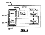
- the laptop computer 100 may include one or more peripheral devices 102 (e.g., a hard disk drive (HDD) or a DVD drive) that have more than one voltage requirement as shown in FIG. 9 .
- the peripheral device 102 may require a first voltage of 5V for a mechanical element such as a motor 104.
- the peripheral device 102 may require a second, lower voltage for another electronic element 106.
- the electronic element 106 may be able to operate at a range of supply voltages.
- the electronic element 106 may operate on power from a single LiOn battery source or a supply voltage of 5V. In conventional systems that operate at 5V in a series arrangement, the electronic element 106, as well as the mechanical element 104, operate at 5V.
- the peripheral device 102 may also operate in a parallel distribution arrangement in the laptop computer 100.
- the laptop computer 100 includes a step-up DC/DC converter 108 that provides 5V to the mechanical element 104.
- a second step-up DC/DC converter is not required for the electronic element 106.
- the electronic element 106 is configured to operate at a lower supply voltage as well as operate at 5V, which negates the need for an additional step-up DC/DC converter.
- a laptop computer 110 converts a battery voltage to a 5V supply voltage according to a two-stage DC/DC conversion process.
- the battery is a Lithium-lon battery, although other types of batteries may be used.
- the laptop computer 110 includes a DC/DC converter 112, a step-down DC/DC converter 114, and a 1:n step-up DC/DC converter 116.
- the DC/DC converter 112 may be a step-down or step-up converter according to the voltage requirements of the load 118.
- the DC/DC converter 112 converts the voltage of a battery 120 as described in previous implementations.
- the use of a step-up boost converter may be less desirable for certain high current applications.
- the voltage of the battery 124 may be between 2.7V and 4.2V.
- the step-down DC/DC converter 114 first converts the voltage of a battery 124 to a lower voltage.
- the step-down DC/DC converter 114 converts the voltage of the battery 124 to 2.5V.
- the step-up DC/DC converter 116 subsequently converts the lower voltage to a higher voltage suitable for the load 122.
- the step-up DC/DC converter 116 has a 1:2 conversion ratio and converts the output of the step-down DC/DC converter 114 to 5V.
- the step-up DC/DC converter 116 may have a 1:n conversion ratio as necessary.
- a power supply or battery pack may implement a parallel battery distribution with universal serial bus (USB) technology according to any of the implementations described herein.
- USB universal serial bus
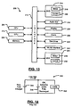
- the mobile computing device 200 includes a central processing unit (CPU) 204, memory 206 (such as random access memory, read only memory, and/or other suitable electronic storage) and an input/output (I/O) interface 210.
- the device 200 may further include a graphics processing unit (GPU) 212.
- the mobile computing device 200 may include one or more peripheral devices such as a DVD drive 214, which includes one or more motors 218 and control 220. Additional peripheral devices may include a hard disk drive (HDD) 224, which may include one or more motors 228 and a control module to 230.
- the device 200 may include an audio output 232 such as an audio output jack or speaker.
- the device may include a display 234, inputs 236, a disk drive 240 and/or a wireless local area network interface 242.
- the inputs 236 may include audio input, a microphone, a kepypad, buttons, touch pad and/or other inputs.
- Components of the device 200 may be grouped into one or more distributed load centers and supplied in the manner described above.
- a circuit 240 includes a first battery 244 and a second battery 248.
- the batteries 244 and 248 are connected in parallel and supply one or more loads 250.
- the first battery 244 is a new and/or fully charged battery and the second battery 248 is in old, defective and/or fully discharged battery, current flowing to the second battery 248 may be too high and cause damage and/or other hazards.
- a mobile computing device 300 includes a distributed power source 302 and current sense and protection modules according to the present invention.
- the device 300 includes batteries 304-1, 304-2, 304-3, and 304-4 (collectively batteries 304) that primarily supply loads 306-1, 306-2, 306-3, and 306-4 (collectively loads 306), respectively.
- Sensing and protection modules 310-1, 310-2, 310-3, and 310-4 are connected to the batteries 304-1, 304-2, 304-3, and 304-4, respectively.
- the sensing and protection modules 310-1, 310-2, 310-3, and 310-4 sense current flowing through the batteries 304-1, 304-2, 304-3, and 304-4 in any suitable manner and limit current as will be described below.
- a control module 320 communicates with the sensing and protection modules 310, receives a sensed current signal, and generates one or more control signals to control current flowing through the batteries 304. While four battery/load/sensing and protection module pairs are shown, additional or fewer pairs may be used in a particular implementation.
- the current protection module 330 includes a plurality of transistors 330-1, 330-2, 330-3, ..., and 330-N. When current flowing through a respective battery is sufficiently low, the transistors 330 are turned on. When current exceeds a threshold, the transistors 330 are modulated and/or turned off to adjust a resistance R DS provided by each transistor 330. Some of the transistors can be selectively turned on while others are off. While parallel arrangement is shown, a series arrangement can also be used.
- another current protection circuit 340 includes a resistance 342 and a parallel connected switch 344.
- the switch 344 is normally closed. When current through a respective battery increases above a threshold, the switch 344 is opened to increase series resistance by adding the resistance 342. As a result, current flowing through the battery decreases.
- FIG. 16C another current protection circuit 350 shown to include a variable resistance 352 and a parallel connected switch 354.
- the switch 354 is normally closed. When current through the battery increases above a threshold, the switch is opened to increase series resistance by adding the variable resistance 352. The resistance that is provided may be adjusted by the control module 320. As a result, current flowing through the battery decreases.
- the batteries may be single cell batteries.
- the resistances can be implemented using resistors, transistors or other suitable components.
- the switches may be implemented using transistors or other suitable components.
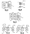
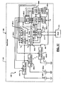
- a medical device such as a pacemaker system 400 is shown.
- the pacemaker system 400 is fully redundant.
- a bad or low battery can be isolated reliably from good or charged batteries.
- a bad or inoperable circuit such as a control module or pulse generator can be reliably isolated from good or operable circuits. Outputs of selected control modules and/or pulse generators can be reliably combined to allow redundancy. As a result, the reliability of the pacemaker system 400 can be improved.
- the pacemaker system 400 includes pulse generators 404A and 404B (collectively, pulse generators 404), switch modules 405-1, 405-2, ..., 405-6 (collectively, switch modules 405) and control modules 408A and 408B (collectively, control modules 404A and 404B).
- pulse generators 404A and 404B collectively, pulse generators 404
- switch modules 405-1, 405-2, ..., 405-6 collectively, switch modules 405
- control modules 408A and 408B collectively, control modules 404A and 404B
- One or more leads 412 connect a selected pulse generator 404 to a patient's heart 414.
- a sealed housing 424 may be used to house components of the medical device.
- the pulse generators 404 and control modules 408 may be integrated into one or more combination modules.
- the switch modules 405, control modules 408, and/or the pulse generators 404 can be combined into one or more integrated circuits.
- a selected one of the control modules 408 controls a first switch module 405-1, which selects an output of one of the pulse generators 404.
- the selected pulse generator 404 is then connected by the switch module 405-1 to the leads 412.
- the pulse generators 404 receive and process signals generated by the patient's heart 414 and selectively deliver heart pacing pulses to the heart 414 as directed by the selected one of the control modules 408.
- a second switch module 405-2 connects one of the switch and protection modules 430-1, 430-2, ... 430-K (collectively, switch and protection modules 430) to one or more of the control modules 408.
- switch modules 405-2 and 405-1 can be actuated to select the other pulse generator 404 or control module 408.
- a power distribution system 420 includes a plurality of batteries 450-1, 450-2, ..., and 450-K (collectively, batteries 450) that can be connected in parallel.
- the power distribution system 420 also includes the switch and protection modules 430.
- Each switch and protection module 430 communicates with one or more of the control modules 408 via the second switch module 405-2 and selectively connects one or more of the batteries 450 to a common voltage rail or node 456.
- the common voltage rail 456 provides power to switch modules 405-3, 405-4, 405-5 and 405-6, which selectively provide power to the pulse generators 404A and 404B and the control modules 408A and 408B, respectively, of the pacemaker system 400.
- the switch and protection modules 430 may sense current flowing from the respective battery 450 and/or voltage across the respective battery 450. This current and/or voltage information is communicated to the control modules 408.
- the control modules 408 direct the switch and protection modules 430 to connect and/or disconnect the respective batteries 450 as needed.
- the control modules 408 may also instruct the switch and protection modules 430 to actively adjust current flow from the batteries 450 using an approach described above in conjunction with FIGs. 16A-16C .
- the control modules 408 may test one of the batteries 450 to ensure sufficient charge prior to switching it onto the common voltage rail 456.
- the control modules 408 may measure, calculate, and store states of charge of each battery.
- the states of charge may be based on open circuit voltage, load testing (e.g., sequentially connecting and measuring high-resistance and low-resistance dummy loads), and/or other suitable approaches.
- the control modules 408 selectively connect respective batteries 450 to the common voltage rail 456 as needed.
- a single battery 450 is connected until its reserve power falls below a threshold.
- the control modules 408 then disconnects the battery 450 and simultaneously connects another battery.
- Capacitive and/or inductive circuits and/or filters may be provided to temporarily power the device during switching to another battery.
- more than one battery 450 can be active at a time, and the control modules 408 may then adjust and/or limit total power and/or total current to a predetermined level.
- the ability to provide additional batteries 450 in the pacemaker system 400 increases the life of the pacemaker system 400.
- the redundancy also improves reliability and increases battery life.
- the pacemaker system 400 may function in a patient for longer periods of time.
- the switch and protection modules 430 provide additional safety when using multiple batteries 450 by limiting excess current.
- the control modules 408A and 408B may be connected together and exchange information. For example, both can be active at all times.
- the watchdog processor may send predetermined data to the active processor and check the returned data to diagnose operability of the active processor. If the active processor does not respond correctly, the watchdog processor and/or another control module may become the active processor.
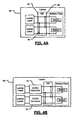
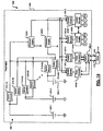
- an alternate pacemaker system 500 which includes the pulse generator modules 404, the switch modules 405, the control modules 408, the leads 412, a power distribution system 504, and the sealed housing 424 that are arranged in an alternate configuration.
- a first switch module 405-3 selects one of the pulse generators 404.
- the selected pulse generator 404 is connected to the leads 412.
- the pulse generators 404 receive and process signals generated by the patient's heart 414 and selectively deliver impulses to the heart 414 as directed by the control modules 408.
- the control modules 408A and 408B are connected to the switch modules 405, protection modules 520A and 520B (collectively, protection modules 520) and/or the pulse generators 404 as generally shown at "S", “P” and “PG” in FIG. 18 .
- the protection modules 520A and 520B are connected by switch modules 405-1, 405-2, 405-4 and 405-5 to the pulse generators 404A and 404B and the control modules 408A and 408B.
- switch modules 405 can be adjusted to select another pulse generator 404 or control module 408.
- the power distribution system 504 includes the plurality of batteries 450 and switch modules 510.
- the batteries 450 are each selectively connected to the first protection module 520A by respective switch modules 510-1A, 510-2A, ..., and 510-KA. Additionally, the batteries 450 are each selectively connected to the second protection module 520B by respective switch modules 510-1B, 510-2B, ..., and 510-KB.
- the protection modules 520 provide power to the pacemaker system 500. Because both protection modules 520 are connected to the selected control module 408, if one protection module 520 fails, the other can be used. If one of the switch modules 510 fails, the other protection module 520 can be used. Furthermore, if for example switch modules 510-1A and 510-2B both fail, both protection modules 520 can be used to allow access to both batteries 450-1 and 450-2.
- the control modules 408 may selectively monitor current flowing through the switch modules 510 and/or protection modules 520 to determine when to selectively connect and/or disconnect batteries 450.
- the control modules 408 may also selectively limit current flowing from the batteries 450 using the protection modules 450, possibly in a manner similar to that described above with respect to FIGs 16A-16C .
- each battery 450 may have a measurement module (not shown) that measures current and/or voltage of the respective battery 450. This information may be transmitted to the control modules 408.
- Each battery 450 may additionally have an associated protection module (individual versions of the protection modules 520) to individually limit its current.
- the control modules 408 in FIG. 18 can also operate in a watchdog processing mode as described above.
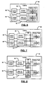
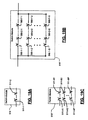
- the redundant switch module 510 includes first and second switch modules 511-1 and 511-2 that are connected in series.
- the redundant switch module 510' includes an F by G array of switch modules 560, where F and G are integers greater than one. For example, F and G may both be equal to 2.
- the F switch modules 560-1-x, 560-2-x, ..., and 560-F-x are connected in series with one another. This is true for each x from 1 to G.
- the G sets of F switch modules are connected in parallel with each other. This built-in redundancy increases reliability.
- N switch modules 510 are combined to provide multiple line switch modules 510". While specific examples of the switch modules are shown, the switch modules may include one or more switches connected in any suitable configuration.
- the pacemaker system 600 which is fully redundant, includes batteries 602-1, 602-2, ..., and 602-C (collectively batteries 602), pulse generators 604-1, 604-2, ..., and 604-D (collectively, pulse generators 604), control modules 608-1, 608-2, ..., and 608-E (collectively, control modules 608), switch modules 610-1, 610-2, ..., and 610-F, and one or more leads 612 connected to a patient's heart 614.
- batteries 602-1, 602-2, ..., and 602-C collectively batteries 602
- pulse generators 604-1, 604-2, ..., and 604-D collectively, pulse generators 604
- control modules 608-1, 608-2, ..., and 608-E collectively, control modules 608-F
- switch modules 610-1, 610-2, ..., and 610-F switch modules 610-1, 610-2, ..., and 610-F
- switch modules 610 When one of the batteries 602 fails, another of the batteries 602 can be connected using switch modules 610. When one of the pulse generators 604 or control modules 608 fails, another of the control modules 608 and/or pulse generators 604 can be connected using the switch modules 610. Additional levels of redundancy can be added using additional switch modules 610-1, 610-2, ..., and 610-G as shown in FIG. 21 .
- control modules pulse generators, batteries and switch module can be varied depending upon the particular application.
Landscapes
- Engineering & Computer Science (AREA)
- Power Engineering (AREA)
- Charge And Discharge Circuits For Batteries Or The Like (AREA)
- Electrotherapy Devices (AREA)
Applications Claiming Priority (4)
| Application Number | Priority Date | Filing Date | Title |
|---|---|---|---|
| US68591505P | 2005-05-31 | 2005-05-31 | |
| US70890305P | 2005-08-17 | 2005-08-17 | |
| US11/216,843 US7610498B2 (en) | 2005-05-31 | 2005-08-31 | Very low voltage power distribution for mobile devices |
| US11/324,450 US7725182B2 (en) | 2005-05-31 | 2006-01-03 | Power distribution system for a medical device |
Publications (2)
| Publication Number | Publication Date |
|---|---|
| EP1728533A1 EP1728533A1 (en) | 2006-12-06 |
| EP1728533B1 true EP1728533B1 (en) | 2009-03-18 |
Family
ID=36940747
Family Applications (1)
| Application Number | Title | Priority Date | Filing Date |
|---|---|---|---|
| EP06009378A Ceased EP1728533B1 (en) | 2005-05-31 | 2006-05-05 | Medical device |
Country Status (6)
| Country | Link |
|---|---|
| US (1) | US7725182B2 (enExample) |
| EP (1) | EP1728533B1 (enExample) |
| JP (1) | JP5080026B2 (enExample) |
| DE (1) | DE602006005739D1 (enExample) |
| SG (1) | SG127816A1 (enExample) |
| TW (1) | TWI389716B (enExample) |
Families Citing this family (20)
| Publication number | Priority date | Publication date | Assignee | Title |
|---|---|---|---|---|
| US8035368B2 (en) * | 2006-02-13 | 2011-10-11 | Freescale Semiconductor, Inc. | Integrated circuit, universal serial bus on-the-go power source and methods for use therewith |
| US7496460B2 (en) * | 2006-09-06 | 2009-02-24 | Eastway Fair Company Limited | Energy source monitoring and control system for power tools |
| US8212412B1 (en) * | 2007-11-30 | 2012-07-03 | Northern Power Systems Utility Scale, Inc. | Energy storage connection system |
| WO2011060096A2 (en) * | 2009-11-11 | 2011-05-19 | Atieva, Inc. | Interlock mechanism for a multiple battery pack |
| EP2468354A3 (de) * | 2010-12-21 | 2012-09-05 | BIOTRONIK SE & Co. KG | Implantierbares Gerät |
| KR101262524B1 (ko) * | 2011-08-04 | 2013-05-08 | 주식회사 엘지화학 | 이차 전지의 과전류 보호 장치, 보호 방법 및 전지 팩 |
| WO2013028963A1 (en) * | 2011-08-24 | 2013-02-28 | Volcano Corporation | Medical communication hub and associated methods |
| CN103094939A (zh) * | 2011-11-01 | 2013-05-08 | 宏碁股份有限公司 | 电池管理电路 |
| US9543767B2 (en) * | 2012-02-09 | 2017-01-10 | Mitsubishi Electric Corporation | Parallel electricity-storage system and control method thereof |
| US9993273B2 (en) | 2013-01-16 | 2018-06-12 | Mako Surgical Corp. | Bone plate and tracking device using a bone plate for attaching to a patient's anatomy |
| US9566120B2 (en) | 2013-01-16 | 2017-02-14 | Stryker Corporation | Navigation systems and methods for indicating and reducing line-of-sight errors |
| KR102284482B1 (ko) * | 2014-12-11 | 2021-08-02 | 삼성에스디아이 주식회사 | 배터리 팩 |
| JP6667339B2 (ja) * | 2016-03-29 | 2020-03-18 | フクダ電子株式会社 | 心腔内除細動システム、心腔内除細動システムにおける接続装置、及び除細動器 |
| JP6613369B2 (ja) * | 2016-04-26 | 2019-11-27 | マクセル株式会社 | 映像出力システム、映像出力装置、および接続ケーブル |
| US10537395B2 (en) | 2016-05-26 | 2020-01-21 | MAKO Surgical Group | Navigation tracker with kinematic connector assembly |
| US10128648B2 (en) * | 2016-06-20 | 2018-11-13 | Lg Chem, Ltd. | Diagnostic system for a DC-DC voltage converter |
| US10177596B2 (en) | 2016-07-08 | 2019-01-08 | Hewlett Packard Enterprise Development Lp | Backup power manager |
| US12059804B2 (en) | 2019-05-22 | 2024-08-13 | Mako Surgical Corp. | Bidirectional kinematic mount |
| CN110474395A (zh) * | 2019-08-27 | 2019-11-19 | 常州格力博有限公司 | 电力系统 |
| TW202137620A (zh) * | 2020-03-25 | 2021-10-01 | 飛宏科技股份有限公司 | 雙埠電池充電系統及其充電方法 |
Family Cites Families (24)
| Publication number | Priority date | Publication date | Assignee | Title |
|---|---|---|---|---|
| US3631860A (en) * | 1969-10-27 | 1972-01-04 | American Optical Corp | Variable rate pacemaker, counter-controlled, variable rate pacer |
| US3748500A (en) * | 1971-12-22 | 1973-07-24 | F Tam | Multiple redundant power supply |
| DE2216193A1 (de) * | 1972-04-04 | 1973-10-11 | Siemens Ag | Herzschrittmacher |
| JPS52151835A (en) * | 1976-04-30 | 1977-12-16 | Univ Johns Hopkins | Enclosed battery |
| FR2618276B1 (fr) | 1987-07-15 | 1994-04-29 | Crouzet Sa | Dispositif de commutation electronique. |
| JP2959657B2 (ja) | 1993-05-13 | 1999-10-06 | キヤノン株式会社 | 電子機器 |
| JPH0749731A (ja) | 1993-08-09 | 1995-02-21 | Toshiba Corp | ポータブルコンピュータ |
| US5411537A (en) | 1993-10-29 | 1995-05-02 | Intermedics, Inc. | Rechargeable biomedical battery powered devices with recharging and control system therefor |
| JPH07307696A (ja) | 1994-05-12 | 1995-11-21 | Oki Electric Ind Co Ltd | 携帯電子装置 |
| US5571141A (en) * | 1994-09-30 | 1996-11-05 | Intermedics, Inc. | Device and method for cardiac arrhythmia therapy with failure detection and backup |
| JP3733554B2 (ja) | 1994-10-31 | 2006-01-11 | 富士通株式会社 | バッテリ駆動型電子機器 |
| SE519632C2 (sv) | 1997-12-23 | 2003-03-25 | Ericsson Telefon Ab L M | Portabel elektronisk apparat med tunnfilmsbatterier samt dessas användning i densamma |
| KR100290988B1 (ko) | 1997-12-29 | 2001-06-01 | 윤종용 | 멀티유니트배터리팩및이멀티유니트배터리팩을사용하는시스템 |
| US6223077B1 (en) * | 1998-01-26 | 2001-04-24 | Physio-Control Manufacturing Corporation | Automatic power switching in a defibrillator |
| JP3580123B2 (ja) | 1998-03-20 | 2004-10-20 | 富士通株式会社 | バッテリ装置 |
| US6130813A (en) * | 1999-01-11 | 2000-10-10 | Dell U.S.A., L.P. | Protection circuit for electronic devices |
| JP4456194B2 (ja) | 1999-03-02 | 2010-04-28 | 富士通マイクロエレクトロニクス株式会社 | 出力回路及びバッテリパック |
| JP2001298952A (ja) | 2000-04-14 | 2001-10-26 | Cosel Co Ltd | スイッチング電源装置 |
| US6977482B2 (en) | 2003-02-11 | 2005-12-20 | O2Micro International Limited | Selector circuit for power management in multiple battery systems |
| US6833983B2 (en) | 2002-02-11 | 2004-12-21 | Intel Corporation | Current limiting super capacitor charger |
| US20040109374A1 (en) | 2002-09-12 | 2004-06-10 | Rajagopalan Sundar | Failure tolerant parallel power source configuration |
| US7791319B2 (en) | 2003-02-21 | 2010-09-07 | Research In Motion Limited | Circuit and method of operation for an electrical power supply |
| US7209784B2 (en) * | 2003-03-31 | 2007-04-24 | Medtronic, Inc. | High power implantable battery with improved safety and method of manufacture |
| US7560829B2 (en) | 2004-12-31 | 2009-07-14 | Intel Corporation | Power system using multiple battery pack types |
-
2006
- 2006-01-03 US US11/324,450 patent/US7725182B2/en not_active Expired - Fee Related
- 2006-05-05 EP EP06009378A patent/EP1728533B1/en not_active Ceased
- 2006-05-05 DE DE602006005739T patent/DE602006005739D1/de active Active
- 2006-05-16 SG SG200603159A patent/SG127816A1/en unknown
- 2006-05-17 TW TW095117464A patent/TWI389716B/zh not_active IP Right Cessation
- 2006-05-24 JP JP2006144471A patent/JP5080026B2/ja not_active Expired - Fee Related
Also Published As
| Publication number | Publication date |
|---|---|
| US7725182B2 (en) | 2010-05-25 |
| JP5080026B2 (ja) | 2012-11-21 |
| TWI389716B (zh) | 2013-03-21 |
| TW200700103A (en) | 2007-01-01 |
| EP1728533A1 (en) | 2006-12-06 |
| JP2006334401A (ja) | 2006-12-14 |
| US20060267551A1 (en) | 2006-11-30 |
| DE602006005739D1 (de) | 2009-04-30 |
| SG127816A1 (en) | 2006-12-29 |
Similar Documents
| Publication | Publication Date | Title |
|---|---|---|
| EP1728533B1 (en) | Medical device | |
| JP2012256343A (ja) | モバイル機器用超低電圧電力供給 | |
| US7633284B2 (en) | Method and apparatus for managing ultracapacitor energy storage systems for a power transmission system | |
| US20090218984A1 (en) | Battery charger | |
| US7126310B1 (en) | Apparatus and method for balanced charging of a multiple-cell battery pack | |
| US4638175A (en) | Electric power distribution and load transfer system | |
| US20050191528A1 (en) | Battery energy storage module | |
| ES2793924T3 (es) | Método y sistema para equilibrar celdas de almacenamiento de energía eléctrica | |
| KR102811048B1 (ko) | 배터리 장치의 충전 상태를 결정하기 위한 전자 장치 및 상기 전자 장치의 동작 방법 | |
| US8467872B2 (en) | Fault-tolerant high voltage delivery in an implantable medical device | |
| KR20180039454A (ko) | 진단 장치 및 이를 포함하는 전원 시스템 | |
| EP2990812B1 (en) | Battery monitoring device and battery system using same | |
| WO2016111987A1 (en) | Energy devices with ultra-capacitor structures and methods thereof | |
| US9077189B2 (en) | Battery protection circuit module device | |
| US20240136827A1 (en) | Method of Battery Balancing an Electrical Series String of Lithium-Ion Batteries, and System Thereof | |
| US20170093184A1 (en) | Method, system and device for power cell management | |
| JP6707373B2 (ja) | セルバランス装置 | |
| CN116470616A (zh) | 一种模拟控制架构及穿戴电子设备 | |
| US20230361581A1 (en) | Integrated control and monitoring of ultracapacitor charging and cell balancing | |
| WO2014039424A1 (en) | System and method of power control for a high-availability system | |
| HK1099241A (en) | Medical device | |
| US20240332988A1 (en) | Battery pack | |
| CN116505614A (zh) | 电池防护方法、电路、电池以及医疗设备 | |
| US11075411B2 (en) | Protection circuit module, battery pack, and method of manufacturing the battery pack | |
| KR102291534B1 (ko) | 스마트 스위칭 기능이 내장된 전지팩 |
Legal Events
| Date | Code | Title | Description |
|---|---|---|---|
| PUAI | Public reference made under article 153(3) epc to a published international application that has entered the european phase |
Free format text: ORIGINAL CODE: 0009012 |
|
| AK | Designated contracting states |
Kind code of ref document: A1 Designated state(s): AT BE BG CH CY CZ DE DK EE ES FI FR GB GR HU IE IS IT LI LT LU LV MC NL PL PT RO SE SI SK TR |
|
| AX | Request for extension of the european patent |
Extension state: AL BA HR MK YU |
|
| 17P | Request for examination filed |
Effective date: 20070525 |
|
| 17Q | First examination report despatched |
Effective date: 20070621 |
|
| AKX | Designation fees paid |
Designated state(s): DE FR GB |
|
| GRAP | Despatch of communication of intention to grant a patent |
Free format text: ORIGINAL CODE: EPIDOSNIGR1 |
|
| GRAS | Grant fee paid |
Free format text: ORIGINAL CODE: EPIDOSNIGR3 |
|
| GRAA | (expected) grant |
Free format text: ORIGINAL CODE: 0009210 |
|
| AK | Designated contracting states |
Kind code of ref document: B1 Designated state(s): DE FR GB |
|
| REG | Reference to a national code |
Ref country code: GB Ref legal event code: FG4D |
|
| REF | Corresponds to: |
Ref document number: 602006005739 Country of ref document: DE Date of ref document: 20090430 Kind code of ref document: P |
|
| PLBE | No opposition filed within time limit |
Free format text: ORIGINAL CODE: 0009261 |
|
| STAA | Information on the status of an ep patent application or granted ep patent |
Free format text: STATUS: NO OPPOSITION FILED WITHIN TIME LIMIT |
|
| 26N | No opposition filed |
Effective date: 20091221 |
|
| REG | Reference to a national code |
Ref country code: FR Ref legal event code: PLFP Year of fee payment: 11 |
|
| REG | Reference to a national code |
Ref country code: FR Ref legal event code: PLFP Year of fee payment: 12 |
|
| PGFP | Annual fee paid to national office [announced via postgrant information from national office to epo] |
Ref country code: DE Payment date: 20170530 Year of fee payment: 12 Ref country code: FR Payment date: 20170525 Year of fee payment: 12 Ref country code: GB Payment date: 20170530 Year of fee payment: 12 |
|
| REG | Reference to a national code |
Ref country code: DE Ref legal event code: R119 Ref document number: 602006005739 Country of ref document: DE |
|
| GBPC | Gb: european patent ceased through non-payment of renewal fee |
Effective date: 20180505 |
|
| PG25 | Lapsed in a contracting state [announced via postgrant information from national office to epo] |
Ref country code: DE Free format text: LAPSE BECAUSE OF NON-PAYMENT OF DUE FEES Effective date: 20181201 Ref country code: GB Free format text: LAPSE BECAUSE OF NON-PAYMENT OF DUE FEES Effective date: 20180505 Ref country code: FR Free format text: LAPSE BECAUSE OF NON-PAYMENT OF DUE FEES Effective date: 20180531 |