EP1727244B1 - Kombileiste - Google Patents
Kombileiste Download PDFInfo
- Publication number
- EP1727244B1 EP1727244B1 EP20060010765 EP06010765A EP1727244B1 EP 1727244 B1 EP1727244 B1 EP 1727244B1 EP 20060010765 EP20060010765 EP 20060010765 EP 06010765 A EP06010765 A EP 06010765A EP 1727244 B1 EP1727244 B1 EP 1727244B1
- Authority
- EP
- European Patent Office
- Prior art keywords
- connector
- housing
- opening
- stop element
- connector element
- Prior art date
- Legal status (The legal status is an assumption and is not a legal conclusion. Google has not performed a legal analysis and makes no representation as to the accuracy of the status listed.)
- Ceased
Links
Images



Classifications
-
- H—ELECTRICITY
- H01—ELECTRIC ELEMENTS
- H01R—ELECTRICALLY-CONDUCTIVE CONNECTIONS; STRUCTURAL ASSOCIATIONS OF A PLURALITY OF MUTUALLY-INSULATED ELECTRICAL CONNECTING ELEMENTS; COUPLING DEVICES; CURRENT COLLECTORS
- H01R24/00—Two-part coupling devices, or either of their cooperating parts, characterised by their overall structure
- H01R24/38—Two-part coupling devices, or either of their cooperating parts, characterised by their overall structure having concentrically or coaxially arranged contacts
- H01R24/40—Two-part coupling devices, or either of their cooperating parts, characterised by their overall structure having concentrically or coaxially arranged contacts specially adapted for high frequency
- H01R24/50—Two-part coupling devices, or either of their cooperating parts, characterised by their overall structure having concentrically or coaxially arranged contacts specially adapted for high frequency mounted on a PCB [Printed Circuit Board]
-
- H—ELECTRICITY
- H01—ELECTRIC ELEMENTS
- H01R—ELECTRICALLY-CONDUCTIVE CONNECTIONS; STRUCTURAL ASSOCIATIONS OF A PLURALITY OF MUTUALLY-INSULATED ELECTRICAL CONNECTING ELEMENTS; COUPLING DEVICES; CURRENT COLLECTORS
- H01R12/00—Structural associations of a plurality of mutually-insulated electrical connecting elements, specially adapted for printed circuits, e.g. printed circuit boards [PCB], flat or ribbon cables, or like generally planar structures, e.g. terminal strips, terminal blocks; Coupling devices specially adapted for printed circuits, flat or ribbon cables, or like generally planar structures; Terminals specially adapted for contact with, or insertion into, printed circuits, flat or ribbon cables, or like generally planar structures
- H01R12/70—Coupling devices
- H01R12/71—Coupling devices for rigid printing circuits or like structures
- H01R12/712—Coupling devices for rigid printing circuits or like structures co-operating with the surface of the printed circuit or with a coupling device exclusively provided on the surface of the printed circuit
- H01R12/714—Coupling devices for rigid printing circuits or like structures co-operating with the surface of the printed circuit or with a coupling device exclusively provided on the surface of the printed circuit with contacts abutting directly the printed circuit; Button contacts therefore provided on the printed circuit
-
- H—ELECTRICITY
- H01—ELECTRIC ELEMENTS
- H01R—ELECTRICALLY-CONDUCTIVE CONNECTIONS; STRUCTURAL ASSOCIATIONS OF A PLURALITY OF MUTUALLY-INSULATED ELECTRICAL CONNECTING ELEMENTS; COUPLING DEVICES; CURRENT COLLECTORS
- H01R13/00—Details of coupling devices of the kinds covered by groups H01R12/70 or H01R24/00 - H01R33/00
- H01R13/62—Means for facilitating engagement or disengagement of coupling parts or for holding them in engagement
- H01R13/629—Additional means for facilitating engagement or disengagement of coupling parts, e.g. aligning or guiding means, levers, gas pressure electrical locking indicators, manufacturing tolerances
- H01R13/631—Additional means for facilitating engagement or disengagement of coupling parts, e.g. aligning or guiding means, levers, gas pressure electrical locking indicators, manufacturing tolerances for engagement only
- H01R13/6315—Additional means for facilitating engagement or disengagement of coupling parts, e.g. aligning or guiding means, levers, gas pressure electrical locking indicators, manufacturing tolerances for engagement only allowing relative movement between coupling parts, e.g. floating connection
-
- H—ELECTRICITY
- H01—ELECTRIC ELEMENTS
- H01R—ELECTRICALLY-CONDUCTIVE CONNECTIONS; STRUCTURAL ASSOCIATIONS OF A PLURALITY OF MUTUALLY-INSULATED ELECTRICAL CONNECTING ELEMENTS; COUPLING DEVICES; CURRENT COLLECTORS
- H01R2103/00—Two poles
Definitions
- the present invention relates to an electrical connector, in particular a combination strip with a plurality of contact elements.
- US-A-5,234,353 discloses a low connection force, long life hybrid input / output connector having a series of signal contacts arranged between two coaxial connectors.
- the coaxial connectors are rigidly mounted in the connector by locking and thus are not axially displaceable.
- EP-A-1 246 314 discloses a multi-pole plug-in device with amidk.him, which are arranged in an axially displaceable insert.
- the additional contact units are contacted with additional contact counter units, while when axially connected to a standard coupling, the axially displaceable insert is displaced axially by inward urging of flexible wall regions of the insert becomes.
- the object of the invention is to provide a connector to which both at least one shielded high frequency line and at least one unshielded line can be connected.
- an inexpensive method for producing a circuit board with a connector arranged thereon is to be provided.
- a connector for electrical connection to a circuit board comprising: a housing for receiving at least one contact element and an opening for receiving a connector element; and a connector element which can be inserted into the opening of the housing and which is axially displaceable in the opening when inserted, wherein on a rear side of the connector element a first stop element, preferably in the shape of a collar, and on a front side a second stop element, preferably in shape a collar is disposed, and between the first and second stopper member, a middle portion is provided with a smaller thickness, which has a greater axial length than the opening to be axially movable in the opening of the housing.
- the second abutment member of the connector member has a slightly greater thickness than the dimension of the opening of the connector housing so that the connector member is mountable by pushing the second abutment member into the opening of the connector housing.
- the connector member By having the connector element inserted into the opening of the housing having first and second abutment members respectively at the front and rear sides, the connector member may be interposed between the two abutments in the opening of the housing move axially back and forth. As a result, manufacturing tolerances of the components are compensated.
- the housing When the connector is electrically connected to a circuit board, the housing is placed on the board, so that the contact elements come into contact with respective contact points or tracks of the board.
- a length compensation of the contact elements takes place by an axial displaceability of the contact elements.
- a length compensation of the connector element or the coaxial connector takes place by the axial displaceability of the connector element in the opening of the housing.
- a contact element of the connector element may contact a corresponding contact point of the board without high manufacturing tolerances of the connector element, the housing and the contact elements must be complied with.
- the connector element can be easily inserted into the opening of the connector housing when the first collar of the connector element has a slightly greater thickness than the dimension of the opening of the connector housing, so that mounting can be done simply by inserting the connector element into the opening of the connector housing is pressed.
- the slightly larger thickness of the first collar then acts as a stop surface of the connector element to limit axial displacement of the connector element in the opening of the connector housing.
- the second stop member of the connector element has a substantially circular cross section or is slightly conical and the opening in the housing is substantially cylindrical or slightly conical, preferably either the opening in the housing is conical and the second stop element is circular or the second stop element is conical and the opening in the housing is circular.
- a cone angle is in the range of 1 ° to 15 °, preferably 7 ° to 10 °.
- axial play of the connector element in the opening of the housing is in the range of 0.05 to 3 mm, more preferably in the range of 1 to 2 mm.
- the connector element is a coaxial connector or socket.
- a plurality of contact elements for electrical connection to a circuit board is arranged in the housing.
- the housing has at one lateral end portion guide elements for engaging with complementary guide elements of a complementary housing.
- a method of manufacturing a circuit board having a connector disposed thereon comprising the steps of: providing a connector housing having at least one contact element and an opening, providing a connector element having a substantially elongated body, wherein a first abutment element at a back side of the connector element and a second stopper member is disposed on a front side, and between the first and second stopper members, a middle portion of lesser thickness having a greater axial length than the opening to be axially movable in the opening of the housing, inserting the connector element in the opening so that the connector element in the opening is axially displaceable, and placing the connector housing on a board and establishing an electrical connection of the at least one contact element and a contact element of the connector element with d he board.
- FIG. 1 shows an exploded perspective view of an embodiment of the connector according to the invention.
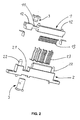
- FIG. 2 shows an exploded perspective view of a connector according to the invention together with a complementary connector.
- FIG. 3 shows a perspective view of the connector according to the invention, when it is electrically connected to a circuit board, and the complementary connector prior to insertion of the two connectors into each other.
- FIG. 4 shows a perspective view similar to FIG. 3 However, in the complementary connector, the connector element 3 is taken out.
- the connector has a housing 1 for receiving a Variety of contact elements 13.
- the contact elements 13 are arranged in the housing, that an axial displacement is ensured to align the contact elements 13 when electrically connected to a circuit board in its longitudinal direction.
- an opening 11 for receiving a connector element 3 is provided in an extension of the tab.
- the connector element 3 has a first stop element 21, preferably in the shape of a collar, a second stop element 22, preferably in the shape of a collar, and a middle section 23.
- the second collar 22 has a slightly larger diameter than the opening 11. For inserting the Connector element 3, this is pushed through the opening 11.
- the central portion 23 of the connector element 3 has a greater axial length than the opening 11.
- the first collar 31 and the second collar 32 serve as stop members for limiting axial displaceability of the connector element 3 within the aperture 11 after insertion of the connector element 3 into the aperture 11. This provides an axial tolerance compensation to align a contact element of the connector element 3 with the contact elements 13 for electrical connection to a circuit board.
- the Figures 3 and 4 show the connector after the electrical connection to a circuit board 4, preferably by soldering with a so-called “Surface Mounted Technology” method (SMT) in a so-called “reflow oven”.
- SMT Surface Mounted Technology
- the connector element 3 is axially displaced by its own weight in the direction of board 4 until the contact element of the connector element 3 comes into contact with a contact point or a contact track on the board 4.
- a tolerance compensation of the manufacturing tolerances of the connector element 3 and the connector housing 1 is provided.
- the elements of the connector can thus be manufactured with relatively low manufacturing tolerances, so that the manufacturing cost is reduced can be. In addition, a yield can be increased, since even high manufacturing tolerances can be compensated by the axial displaceability of the connector element 3.
- FIG. 2 shows an exploded perspective view of the connector according to the invention and a complementary connector with a housing 2.
- the complementary connector with the housing 2 is similar to the connector with the housing 1 constructed and also has an opening 21 for insertion of a connector element 3.
- the opening 21 of the housing 2 has at least one groove to allow insertion of a connector element 3 with a projection on the circumference.
- the connector element 3 for insertion into the housing 2 may also include, like the connector element 3 for insertion into the housing 1, a first collar, a second collar and a central portion.
- the two housings 1, 2 have guide elements 12, 22 in order to align the two housings 1, 2 during insertion into one another.
- one of the housings 1 has bores 12, while the other housing 2 has pins 22 which comprise at their end a conical chamfer.
- the second collar 32 of the connector element 3 is tapered at its end to facilitate insertion into the opening 11 of the connector housing 1.
- the second collar 32 of the connector element 3 may also be cylindrical, if instead the opening 11 of the connector housing 1 is conical.
- the cone angle is preferably in the range of 1 to 15 degrees, preferably 7 to 10 degrees.
- the connector housing 1 has sufficient elasticity to allow insertion of the connector element 3 into the opening 11 by corresponding expansion of the material.
- the invention is not limited to the embodiment shown here.
- a connector with only a single contact element 13th instead of the plurality of contact elements 13 shown here are provided.
- a rectangular connector element may be provided for insertion into a rectangular opening in the connector housing. It is only important that the connector element 3 is axially displaceable in the housing and, if a stop element is to be provided, the stop element has a slightly greater thickness than the opening of the connector housing, so that an axial stop of the connector element 3 in the opening 11 of Housing 1 is created.
- the housing 1 must have sufficient elasticity to allow insertion of the connector element 3 by elastic deformation of the opening 11 of the connector housing 1.
Landscapes
- Coupling Device And Connection With Printed Circuit (AREA)
Description
- Die vorliegende Erfindung betrifft einen elektrischen Verbinder, insbesondere eine Kombileiste mit einer Vielzahl von Kontaktelementen.
- Herkömmlich gibt es Flachstecker bzw. Kombileisten mit einer Vielzahl von Kontaktelementen, um eine Vielzahl an elektrischen Leitern miteinander zu verbinden. Außerdem gibt es Koaxialstecker, bei denen mindestens ein Leiter durch eine Abschirmung abgeschirmt ist, um Hochfrequenzsignale zu übertragen bzw. Störungen einer Signalübertragung zu verhindern. Bei vielen elektrischen Geräten, wie beispielsweise einem Navigationssystem gibt es sowohl die erstgenannten Flachstecker als auch die zweitgenannten Koaxialstecker. Um ein derartiges elektrisches Gerät in Betrieb zu setzen, muß ein Anwender sowohl den Flachstecker als auch den Koaxialstecker in den jeweiligen Gegenstecker einstecken. Wünschenswert wäre es jedoch, nur einen einzigen Stecker an dem Gerät zu haben.
-
US-A-5 234 353 offenbart einen Hybrid-Eingangs/Ausgangs-Verbinder mit niedriger Verbindungskraft und hohem Lebenszyklus mit einer Reihe von Signalkontakten, die zwischen zwei Koaxialverbindem angeordnet sind. Die Koaxialverbinder sind in dem Verbinder durch Verriegeln starr angeordnet und somit nicht axial verschiebbar. -
EP-A-1 246 314 offenbart eine mehrpolige Steckvorrichtung mit Zusatzkkontakteinheiten, die in einem axial verschiebbaren Einsatz angeordnet sind. Beim Verbinden der Steckvorrichtung mit einer modifizierten Kupplung erfolgt eine Kontaktierung der Zusatzkontakteinheiten mit Zusatzkontaktgegeneinheiten, während beim Verbinden mit einer Standardkupplung der axial verschiebbare Einsatz durch nach innen Drängen von flexiblen Wandbereichen des Einsatzes axial verschoben wird. - Demgemäß besteht die Aufgabe der Erfindung in der Schaffung eines Verbinders, mit dem sowohl zumindest eine abgeschirmte Hochfrequenzleitung als auch zumindest eine nicht abgeschirmte Leitung verbunden werden kann. Außerdem soll ein kostengünstiges Verfahren zum Herstellen einer Platine mit einem daran angeordneten Verbinder geschaffen werden.
- Diese Aufgabe wird durch einen Verbinder mit den Merkmalen nach Anspruch 1 und ein Herstellverfahren nach Anspruch 10 gelöst. Vorteilhafte Weiterbildungen der Erfindungen sind in den abhängigen Ansprüchen definiert.
- Erfindungsgemäß wird ein Verbinder geschaffen zum elektrischen Verbinden mit einer Platine mit: einem Gehäuse für die Aufnahme von zumindest einem Kontaktelement und einer Öffnung für die Aufnahme eines Verbinderelements; und einem in die Öffnung des Gehäuses einsetzbaren Verbinderelement, das im eingesetzten Zustand in der Öffnung axial verschiebbar ist, wobei an einer Rückseite des Verbinderelements ein erstes Anschlagelement, vorzugsweise in der Gestalt eines Bunds, und an einer Vorderseite ein zweites Anschlagelement, vorzugsweise in der Gestalt eines Bunds angeordnet ist, sowie zwischen dem ersten und zweiten Anschlagelement ein Mittelabschnitt mit geringerer Dicke vorgesehen ist, der eine größere axiale Länge als die Öffnung hat, um in der Öffnung des Gehäuses axial bewegbar zu sein.
- Vorzugsweise hat das zweite Anschlagelement des Verbinderelements eine etwas größere Dicke als die Abmessung der Öffnung des Verbindergehäuses, so dass das Verbinderelement durch Eindrücken des zweiten Anschlagelements in die Öffnung des Verbindergehäuses hinein montierbar ist.
- Indem das in die Öffnung des Gehäuses eingesetzte Verbinderelement ein erstes und ein zweites Anschlagelement jeweils an der Vorder- und Rückseite aufweist, kann das Verbinderelement sich zwischen den beiden Anschlägen in der Öffnung des Gehäuses axial hin und her bewegen. Hierdurch werden Fertigungstoleranzen der Bauteile kompensiert. Wenn der Verbinder mit einer Platine elektrisch verbunden wird, wird das Gehäuse auf die Platine aufgesetzt, so daß die Kontaktelemente mit jeweiligen Kontaktpunkten bzw. -bahnen der Platine in Kontakt treten. Ein Längenausgleich der Kontaktelemente findet durch eine axiale Verschiebbarkeit der Kontaktelemente statt. Ein Längenausgleich des Verbinderelements bzw. des Koaxialsteckers, findet durch die axiale Verschiebbarkeit des Verbinderelements in der Öffnung des Gehäuses statt. In anderen Worten, wenn die Kontaktelemente des Gehäuses sich in Kontakt mit den Kontaktpunkten bzw. -bahnen der Platine befinden, kann ein Kontaktelement des Verbinderelements mit einem entsprechenden Kontaktpunkt der Platine in Kontakt treten, ohne daß hohe Fertigungstoleranzen des Verbinderelements, des Gehäuses und der Kontaktelemente eingehalten werden müssen.
- Das Verbinderelement kann auf einfache Weise in die Öffnung des Verbindergehäuses eingesetzt werden, wenn der erste Bund des Verbinderelements eine etwas größere Dicke als die Abmessung der Öffnung des Verbindergehäuses hat, so daß eine Montage einfach dadurch erfolgen kann, daß das Verbinderelement in die Öffnung des Verbindergehäuses eingedrückt wird. Die etwas größere Dicke des ersten Bundes wirkt dann als Anschlagfläche des Verbinderelements, um eine axiale Verschiebung des Verbinderelements in der Öffnung des Verbindergehäuses zu begrenzen.
- Vorzugsweise hat das zweite Anschlagelement des Verbinderelements im wesentlichen einen kreisrunden Querschnitt oder ist leicht konisch und die Öffnung in dem Gehäuse ist im wesentlichen zylindrisch oder leicht konisch, wobei vorzugsweise entweder die Öffnung in dem Gehäuse konisch ist und das zweite Anschlagelement kreisrund ist oder das zweite Anschlagelement konisch ist und die Öffnung in dem Gehäuse kreisrund ist. Ein Konuswinkel liegt dabei im Bereich von 1 ° bis 15°, vorzugsweise 7° bis 10°.
- Durch Ausbilden eines Konusses entweder in der Öffnung des Gehäuses oder an dem ersten Bund des Verbinderelements, wird ein Einsetzen des Verbinderelements in die Öffnung hinein erleichtert.
- Vorzugsweise liegt ein axiales Spiel des Verbinderelements in der Öffnung des Gehäuses im Bereich von 0,05 bis 3 mm, noch mehr bevorzugt im Bereich von 1 bis 2 mm.
- Vorzugsweise ist das Verbinderelement ein Koaxialverbinder bzw. -stecker bzw. buchse.
- Vorzugsweise ist eine Vielzahl an Kontaktelementen zum elektrischen Verbinden mit einer Platine in dem Gehäuse angeordnet.
- Vorzugsweise weist das Gehäuse an einem seitlichen Endabschnitt Führungselemente zum in Eingriff treten mit komplementären Führungselementen eines komplementären Gehäuses auf.
- Erfindungsgemäß wird des weiteren ein Verfahren geschaffen zum Herstellen einer Platine mit einem daran angeordneten Verbinder mit den Schritten: Bereitstellen eines Verbindergehäuses mit zumindest einem Kontaktelement und einer Öffnung, Bereitstellen eines Verbinderelements mit einem im wesentlichen länglichen Körper, wobei an einer Rückseite des Verbinderelements ein erstes Anschlagelement und an einer Vorderseite ein zweites Anschlagelement angeordnet ist, sowie zwischen dem ersten und zweiten Anschlagelement ein Mittelabschnitt mit geringerer Dicke vorgesehen ist, der eine größere axiale Länge als die Öffnung hat, um in der Öffnung des Gehäuses axial bewegbar zu sein, Einsetzen des Verbinderelements in die Öffnung, so dass das Verbinderelement in der Öffnung axial verschiebbar ist, und Aufsetzen des Verbindergehäuses auf eine Platine und Herstellen einer elektrischen Verbindung des zumindest einen Kontaktelements und eines Kontaktelements des Verbinderelements mit der Platine.
- Die vorliegende Erfindung wird nachfolgend anhand von Zeichnungen bevorzugter Ausführungsformen beispielhaft näher erläutert.
-
Figur 1 zeigt eine perspektivische Explosionsansicht eines Ausführungsbeispiels des erfindungsgemäßen Verbinders. -
Figur 2 zeigt eine perspektivische Explosionsansicht eines erfindungsgemäßen Verbinders zusammen mit einem komplementären Verbinder. -
Figur 3 zeigt eine perspektivische Ansicht des erfindungsgemäßen Verbinders, wenn dieser mit einer Platine elektrisch verbunden ist, sowie des komplementären Verbinders vor dem Einstecken der beiden Verbinder ineinander. -
Figur 4 zeigt eine perspektivische Ansicht ähnlich wieFigur 3 , jedoch ist bei dem komplementären Verbinder das Verbinderelement 3 herausgenommen. - Wie in
Figur 1 gezeigt ist, hat der Verbinder ein Gehäuse 1 für die Aufnahme einer Vielzahl von Kontaktelementen 13. Die Kontaktelemente 13 sind so in dem Gehäuse angeordnet, dass eine axiale Verschiebbarkeit gewährleistet ist, um die Kontaktelemente 13 beim elektrischen Verbinden mit einer Platine in ihrer Längsrichtung auszurichten. - Des weiteren ist in einer Verlängerung des Flachsteckers eine Öffnung 11 für die Aufnahme eines Verbinderelements 3 vorgesehen. Das Verbinderelement 3 hat ein erstes Anschlagelement 21, vorzugsweise in der Gestalt eines Bunds, ein zweites Anschlagelement 22, vorzugsweise in der Gestalt eines Bunds, und einen Mittelabschnitt 23. Der zweite Bund 22 hat einen geringfügig größeren Durchmesser als die Öffnung 11. Zum Einsetzen des Verbinderelements 3 wird dieses durch die Öffnung 11 hindurchgedrückt. Der Mittelabschnitt 23 des Verbinderelements 3 hat eine größere axiale Länge als die Öffnung 11. Der erste Bund 31 und der zweite Bund 32 dienen als Anschlagelemente für die Begrenzung einer axialen Verschiebbarkeit des Verbinderelements 3 innerhalb der Öffnung 11 nach dem Einsetzen des Verbinderelements 3 in die Öffnung 11. Hierdurch wird ein axialer Toleranzausgleich geschaffen, um ein Kontaktelement des Verbinderelements 3 mit den Kontaktelementen 13 zum elektrischen Verbinden mit einer Platine auszurichten.
- Die
Figuren 3 und4 zeigen den Verbinder nach dem elektrischen Verbinden mit einer Platine 4, vorzugsweise durch Löten mit einem sogenannten "Surface Mounted Technology"-Verfahren (SMT) in einem sogenannten "Reflow Oven". Nach dem Aufsetzen des Verbindergehäuses 1 auf die Platine 4 wird das Verbinderelement 3 durch sein Eigengewicht so in Richtung Platine 4 axial verschoben, bis das Kontaktelement des Verbinderelements 3 in Kontakt tritt mit einem Kontaktpunkt bzw. einer Kontaktbahn auf der Platine 4. Durch die axiale Verschiebbarkeit des Verbinderelements 3 im Bereich von 0,05 bis 3 mm, vorzugsweise im Bereich von 1 bis 2 mm wird ein Toleranzausgleich der Fertigungstoleranzen des Verbinderelements 3 und des Verbindergehäuses 1 geschaffen. - Die Elemente des Verbinders können somit mit verhältnismäßig geringen Fertigungstoleranzen gefertigt werden, so daß die Herstellungskosten vermindert werden können. Darüber hinaus kann eine Ausbeute erhöht werden, da auch hohe Fertigungstoleranzen durch die axiale Verschiebbarkeit des Verbinderelements 3 kompensiert werden können.
-
Figur 2 zeigt eine perspektivische Explosionansicht des erfindungsgemäßen Verbinders sowie eines komplementären Verbinders mit einem Gehäuse 2. Der komplementäre Verbinder mit dem Gehäuse 2 ist ähnlich wie der Verbinder mit dem Gehäuse 1 aufgebaut und weist ebenfalls eine Öffnung 21 zum Einsetzen eines Verbinderelements 3 auf. Im Gegensatz zu dem Gehäuse 1 weist jedoch die Öffnung 21 des Gehäuses 2 zumindest eine Nut auf, um ein Einsetzen eines Verbinderelements 3 mit einem Vorsprung am Umfang zu ermöglichen. - Obwohl es hier nicht gezeigt ist, kann das Verbinderelement 3 zum Einsetzen in das Gehäuse 2 ebenfalls wie das Verbinderelement 3 zum Einsetzen in das Gehäuse 1 einen ersten Bund, einen zweiten Bund und einen Mittelabschnitt aufweisen.
- Darüber hinaus weisen die beiden Gehäuse 1, 2 Führungselemente 12, 22 auf, um die beiden Gehäuse 1, 2 gegenseitig auszurichten beim Einsetzen ineinander. Vorzugsweise weist eines der Gehäuse 1 Bohrungen 12 auf, während das andere Gehäuse 2 Stifte 22 aufweist, die an ihrem Ende eine konische Fase umfassen.
- Vorzugsweise ist der zweite Bund 32 des Verbinderelements 3 an seinem Ende konisch ausgebildet, um ein Einsetzen in die Öffnung 11 des Verbindergehäuses 1 hinein zu erleichtern. Der zweite Bund 32 des Verbinderelements 3 kann jedoch auch zylindrisch ausgebildet sein, wenn stattdessen die Öffnung 11 des Verbindergehäuses 1 konisch ausgebildet ist. Der Konuswinkel liegt vorzugsweise im Bereich von 1 bis 15 Grad, vorzugsweise 7 - 10 Grad. Das Verbindergehäuse 1 hat eine ausreichende Elastizität, um ein Einsetzen des Verbinderelements 3 in die Öffnung 11 durch entsprechende Dehnung des Materials zu ermöglichen.
- Die Erfindung ist jedoch nicht auf das hier gezeigte Ausführungsbeispiel beschränkt. Insbesondere kann auch ein Verbinder mit nur einem einzigen Kontaktelement 13 anstatt der hier gezeigten Vielzahl an Kontaktelementen 13 vorgesehen werden. Des weiteren kann anstelle des zylindrischen Koaxialsteckers bzw. Buchse als Verbinderelement 3 ein rechteckiges Verbinderelement zum Einsetzen in eine rechteckige Öffnung in dem Verbindergehäuse vorgesehen werden. Es kommt lediglich darauf an, daß das Verbinderelement 3 in dem Gehäuse axial verschiebbar ist und, falls ein Anschlagelement vorgesehen sein soll, das Anschlagelement eine etwas größere Dicke als die Öffnung des Verbindergehäuses aufweist, so daß ein Axialanschlag des Verbinderelements 3 in der Öffnung 11 des Gehäuses 1 geschaffen wird. Darüber hinaus muß das Gehäuse 1 eine ausreichende Elastizität aufweisen, um ein Einsetzen des Verbinderelements 3 durch elastische Verformung der Öffnung 11 des Verbindergehäuses 1 zu ermöglichen.
-
- 1
- Gehäuse
- 11
- Öffnung
- 12
- Führungselemente
- 13
- Kontaktelement
- 2
- Gehäuse
- 21
- Öffnung
- 22
- Führungselemente
- 23
- Kontaktelement
- 3
- Verbinderelement
- 31
- erstes Anschlagelement
- 32
- zweites Anschlagelement
- 33
- Mittelabschnitt
- 4
- Platine
Claims (10)
- Verbinder zum elektrischen Verbinden mit einer Platine mit:einem Gehäuse (1; 2) für die Aufnahme von zumindest einem Kontaktelement (13; 23) und einer Öffnung (11; 21) für die Aufnahme eines Verbinderelements (3);einem in die Öffnung (11; 21) des Gehäuses (1; 2) einsetzbaren Verbinderelement (3), das im eingesetzten Zustand in der Öffnung (11; 21) axial verschiebbar ist,wobei an einer Rückseite des Verbinderelements (3) ein erstes Anschlagelement (31) und an einer Vorderseite ein zweites Anschlagelement (32) sowie zwischen dem ersten und zweiten Anschlagelement ein Mittelabschnitt (33) mit geringerer Dicke vorgesehen ist, der eine größere axiale Länge als die Öffnung (11; 21) hat, um in der Öffnung (11; 21) des Gehäuses (1, 2) axial bewegbar zu sein.
- Verbinder nach Anspruch 1, wobei das zweite Anschlagelement (32) des Verbinderelements (3) eine etwas größere Dicke als die Abmessung der Öffnung (11; 21) des Verbindergehäuses (1; 2) hat, so dass das Verbinderelement (3) durch Eindrücken des zweiten Anschlagelements (32) in die Öffnung (11; 21) des Verbindergehäuses (1; 2) hinein montierbar ist.
- Verbinder nach Anspruch 1 oder 2, wobei das zweite Anschlagelement (32) des Verbinderelements (3) im wesentlichen einen kreisrunden Querschnitt hat oder leicht konisch ist und die Öffnung (11; 21) in dem Gehäuse (1; 2) im wesentlichen zylindrisch oder leicht konisch ist.
- Verbinder nach Anspruch 3, wobei entweder die Öffnung (11; 21) in dem Gehäuse (1; 2) konisch ist und das zweite Anschlagelement (32) kreisrund ist oder das zweite Anschlagelement (32) konisch ist und die Öffnung (11; 21) in dem Gehäuse (1; 2) kreisrund ist.
- Verbinder nach Anspruch 3 oder 4, wobei ein Konuswinkel im Bereich von 1° bis 15°, vorzugsweise 7° bis 10°, liegt.
- Verbinder nach einem der vorherigen Ansprüche, wobei ein axiales Spiel des Verbinderelements (3) in der Öffnung (11; 21) des Gehäuses (1; 2) im Bereich von 0,05 bis 3 mm, vorzugsweise im Bereich von 1 bis 2 mm liegt.
- Verbinder nach einem der vorherigen Ansprüche, wobei das Verbinderelement (3) ein Koaxialverbinder ist.
- Verbinder nach einem der vorherigen Ansprüche, wobei eine Vielzahl an Kontaktelementen (13; 23) zum elektrischen Verbinden mit einer Platine (4) in dem Gehäuse (1,;2) angeordnet ist.
- Verbinder nach einem der vorherigen Ansprüche, wobei das Gehäuse (1) an einem seitlichen Endabschnitt Führungselemente (12) zum in Eingriff treten mit komplementären Führungselementen (22) eines komplementären Gehäuses (2) aufweist.
- Verfahren zum Herstellen einer Platine mit einem daran angeordneten Verbinder mit den Schritten:Bereitstellen eines Verbindergehäuses (1; 2) mit zumindest einem Kontaktelement (13; 23) und einer Öffnung (11; 21),Bereitstellen eines Verbinderelements (3) mit einem im wesentlichen länglichen Körper, wobei an einer Rückseite des Verbinderelements (3) ein erstes Anschlagelement (31) und an einer Vorderseite ein zweites Anschlagelement (32) sowie zwischen dem ersten und zweiten Anschlagelement ein Mittelabschnitt (33) mit geringerer Dicke vorgesehen ist, der eine größere axiale Länge als die Öffnung (11; 21) hat, um in der Öffnung (11; 21) des Gehäuses (1, 2) axial bewegbar zu sein,Einsetzen des Verbinderelements (3) in die Öffnung (11; 21), so dass das Verbinderelement (3) in der Öffnung (11, 21) axial verschiebbar ist, undAufsetzen des Verbindergehäuses (1, 2) auf eine Platine (4) und Herstellen einer elektrischen Verbindung des zumindest einen Kontaktelements (13; 23) und eines Kontaktelements des Verbinderelements (3) mit der Platine (4).
Applications Claiming Priority (1)
| Application Number | Priority Date | Filing Date | Title |
|---|---|---|---|
| DE200510024077 DE102005024077A1 (de) | 2005-05-25 | 2005-05-25 | Kombileiste |
Publications (2)
| Publication Number | Publication Date |
|---|---|
| EP1727244A1 EP1727244A1 (de) | 2006-11-29 |
| EP1727244B1 true EP1727244B1 (de) | 2008-07-09 |
Family
ID=36940022
Family Applications (1)
| Application Number | Title | Priority Date | Filing Date |
|---|---|---|---|
| EP20060010765 Ceased EP1727244B1 (de) | 2005-05-25 | 2006-05-24 | Kombileiste |
Country Status (2)
| Country | Link |
|---|---|
| EP (1) | EP1727244B1 (de) |
| DE (2) | DE102005024077A1 (de) |
Family Cites Families (9)
| Publication number | Priority date | Publication date | Assignee | Title |
|---|---|---|---|---|
| US4697859A (en) * | 1986-08-15 | 1987-10-06 | Amp Incorporated | Floating coaxial connector |
| GB2243034B (en) * | 1990-03-13 | 1994-10-19 | Kokusai Electric Co Ltd | Electrical connectors |
| US5234353A (en) * | 1992-03-03 | 1993-08-10 | Amp Incorporated | Hybrid input/output connector having low mating force and high cycle life and contacts therefor |
| JP2671729B2 (ja) * | 1992-09-29 | 1997-10-29 | 住友電装株式会社 | コネクタ装置 |
| DE4309155C2 (de) * | 1993-03-22 | 1995-06-01 | Itt Cannon Gmbh | Steckverbinder, insbesondere für ein Mobiltelefon |
| US5538435A (en) * | 1994-09-14 | 1996-07-23 | The Whitaker Corporation | Electrical input/output connector with switchable contacts |
| US5718592A (en) * | 1995-11-16 | 1998-02-17 | The Whitaker Corporation | Surface mountable electrical connector assembley |
| US6224407B1 (en) * | 1997-12-17 | 2001-05-01 | The Whitaker Corporation | Coaxial switch connector assembly |
| DE10112118B4 (de) * | 2001-03-14 | 2007-11-29 | Aloys Mennekes Anlagengesellschaft Mbh & Co. Kg | Mehrpolige Steckvorrichtung |
-
2005
- 2005-05-25 DE DE200510024077 patent/DE102005024077A1/de not_active Ceased
-
2006
- 2006-05-24 EP EP20060010765 patent/EP1727244B1/de not_active Ceased
- 2006-05-24 DE DE200650001048 patent/DE502006001048D1/de active Active
Also Published As
| Publication number | Publication date |
|---|---|
| DE502006001048D1 (de) | 2008-08-21 |
| EP1727244A1 (de) | 2006-11-29 |
| DE102005024077A1 (de) | 2006-11-30 |
Similar Documents
| Publication | Publication Date | Title |
|---|---|---|
| EP3396793B1 (de) | Kontaktkörper für einen steckverbinder | |
| DE69309438T2 (de) | System und steckverbinder für die elektrische zwischenverbindung von leiterplatten | |
| DE10203162B4 (de) | Verbinder | |
| DE69126105T2 (de) | Ein Modul-Koaxialsteckverbinder | |
| DE69826202T2 (de) | Kabelverbinderanordnung | |
| EP2783433B1 (de) | Steckverbinder mit abschirmung | |
| DE69315727T2 (de) | Hybrider Eingangs-Ausgangsverbinder mit schwacher Einrückungskraft und langer Lebensdauer und Kontakten und Verriegelungssystem dafür | |
| EP0772261A2 (de) | Koaxial-Steckverbindung | |
| WO2008043115A1 (de) | Xlr-kabelsteckverbinder | |
| EP0848459A2 (de) | Leitungs-Steckverbindung | |
| DE102015015202B4 (de) | Steckverbinder und Stecksystem | |
| EP3979436B1 (de) | Elektrischer steckverbinder, leiterplattenanordnung und verfahren zur montage einer leiterplattenanordnung | |
| DE10057143C2 (de) | Koaxialsteckanordnung für Hochfrequenzanwendungen | |
| EP3627636B1 (de) | Elektrische steckverbindung, baugruppenverbindung und leiterplattenanordnung | |
| DE112016002791T5 (de) | Gemeinschaftsverbinder | |
| DE69221428T2 (de) | Elektrische Kontaktbuchse | |
| EP3605746B1 (de) | Steckverbinder sowie steckverbindung mit einem solchen steckverbinder | |
| EP3358682B1 (de) | Elektrischer steckverbinder und elektrisches stecksystem | |
| EP3782235B1 (de) | Direktsteckverbinder | |
| EP3989368A1 (de) | Elektrischer steckverbinder, verbindungselement und leiterplattenanordnung | |
| DE68923361T2 (de) | Modulares Verbindersystem mit oberflächenmontierten Verbindern hoher Kontaktelementdichte. | |
| DE69009641T2 (de) | Koaxialer Stiftsteckverbinder mit einer Gruppierung von leitenden zylindrischen Hülsen. | |
| DE60100358T2 (de) | Koaxial-steckverbinder und anordnung mit einem solchen verbinder | |
| DE102017222809A1 (de) | Elektrischer Steckverbinder und Steckverbindung | |
| DE69327005T2 (de) | Werkzeug für kombinationsverbinder |
Legal Events
| Date | Code | Title | Description |
|---|---|---|---|
| PUAI | Public reference made under article 153(3) epc to a published international application that has entered the european phase |
Free format text: ORIGINAL CODE: 0009012 |
|
| AK | Designated contracting states |
Kind code of ref document: A1 Designated state(s): AT BE BG CH CY CZ DE DK EE ES FI FR GB GR HU IE IS IT LI LT LU LV MC NL PL PT RO SE SI SK TR |
|
| AX | Request for extension of the european patent |
Extension state: AL BA HR MK YU |
|
| 17P | Request for examination filed |
Effective date: 20070516 |
|
| AKX | Designation fees paid |
Designated state(s): DE FR GB IT |
|
| GRAP | Despatch of communication of intention to grant a patent |
Free format text: ORIGINAL CODE: EPIDOSNIGR1 |
|
| GRAS | Grant fee paid |
Free format text: ORIGINAL CODE: EPIDOSNIGR3 |
|
| GRAA | (expected) grant |
Free format text: ORIGINAL CODE: 0009210 |
|
| AK | Designated contracting states |
Kind code of ref document: B1 Designated state(s): DE FR GB IT |
|
| REG | Reference to a national code |
Ref country code: GB Ref legal event code: FG4D Free format text: NOT ENGLISH |
|
| REF | Corresponds to: |
Ref document number: 502006001048 Country of ref document: DE Date of ref document: 20080821 Kind code of ref document: P |
|
| PLBE | No opposition filed within time limit |
Free format text: ORIGINAL CODE: 0009261 |
|
| STAA | Information on the status of an ep patent application or granted ep patent |
Free format text: STATUS: NO OPPOSITION FILED WITHIN TIME LIMIT |
|
| 26N | No opposition filed |
Effective date: 20090414 |
|
| REG | Reference to a national code |
Ref country code: DE Ref legal event code: R082 Ref document number: 502006001048 Country of ref document: DE Representative=s name: MUELLER-BORE & PARTNER PATENTANWAELTE, EUROPEA, DE |
|
| REG | Reference to a national code |
Ref country code: FR Ref legal event code: CA Effective date: 20130410 |
|
| REG | Reference to a national code |
Ref country code: DE Ref legal event code: R082 Ref document number: 502006001048 Country of ref document: DE Representative=s name: MUELLER-BORE & PARTNER PATENTANWAELTE PARTG MB, DE Effective date: 20130409 Ref country code: DE Ref legal event code: R082 Ref document number: 502006001048 Country of ref document: DE Representative=s name: MUELLER-BORE & PARTNER PATENTANWAELTE, EUROPEA, DE Effective date: 20130409 Ref country code: DE Ref legal event code: R081 Ref document number: 502006001048 Country of ref document: DE Owner name: YAMAICHI ELECTRONICS DEUTSCHLAND GMBH, DE Free format text: FORMER OWNER: YAMAICHI ELECTRONICS DEUTSCHLAND GMBH, 81829 MUENCHEN, DE Effective date: 20130409 |
|
| REG | Reference to a national code |
Ref country code: FR Ref legal event code: PLFP Year of fee payment: 11 |
|
| REG | Reference to a national code |
Ref country code: FR Ref legal event code: PLFP Year of fee payment: 12 |
|
| REG | Reference to a national code |
Ref country code: FR Ref legal event code: PLFP Year of fee payment: 13 |
|
| PGFP | Annual fee paid to national office [announced via postgrant information from national office to epo] |
Ref country code: GB Payment date: 20240523 Year of fee payment: 19 |
|
| PGFP | Annual fee paid to national office [announced via postgrant information from national office to epo] |
Ref country code: DE Payment date: 20240527 Year of fee payment: 19 |
|
| PGFP | Annual fee paid to national office [announced via postgrant information from national office to epo] |
Ref country code: FR Payment date: 20240527 Year of fee payment: 19 |
|
| PGFP | Annual fee paid to national office [announced via postgrant information from national office to epo] |
Ref country code: IT Payment date: 20240531 Year of fee payment: 19 |
|
| REG | Reference to a national code |
Ref country code: DE Ref legal event code: R119 Ref document number: 502006001048 Country of ref document: DE |
|
| GBPC | Gb: european patent ceased through non-payment of renewal fee |
Effective date: 20250524 |
|
| PG25 | Lapsed in a contracting state [announced via postgrant information from national office to epo] |
Ref country code: GB Free format text: LAPSE BECAUSE OF NON-PAYMENT OF DUE FEES Effective date: 20250524 |
|
| PG25 | Lapsed in a contracting state [announced via postgrant information from national office to epo] |
Ref country code: DE Free format text: LAPSE BECAUSE OF NON-PAYMENT OF DUE FEES Effective date: 20251202 |
|
| PG25 | Lapsed in a contracting state [announced via postgrant information from national office to epo] |
Ref country code: IT Free format text: LAPSE BECAUSE OF NON-PAYMENT OF DUE FEES Effective date: 20250524 |
|
| PG25 | Lapsed in a contracting state [announced via postgrant information from national office to epo] |
Ref country code: FR Free format text: LAPSE BECAUSE OF NON-PAYMENT OF DUE FEES Effective date: 20250531 |