EP1727187A1 - Lamp bulb - Google Patents
Lamp bulb Download PDFInfo
- Publication number
- EP1727187A1 EP1727187A1 EP05719723A EP05719723A EP1727187A1 EP 1727187 A1 EP1727187 A1 EP 1727187A1 EP 05719723 A EP05719723 A EP 05719723A EP 05719723 A EP05719723 A EP 05719723A EP 1727187 A1 EP1727187 A1 EP 1727187A1
- Authority
- EP
- European Patent Office
- Prior art keywords
- filament
- filaments
- electric lamp
- electric
- lamp
- Prior art date
- Legal status (The legal status is an assumption and is not a legal conclusion. Google has not performed a legal analysis and makes no representation as to the accuracy of the status listed.)
- Withdrawn
Links
- 229910052736 halogen Inorganic materials 0.000 claims description 11
- 150000002367 halogens Chemical class 0.000 claims description 11
- 150000002366 halogen compounds Chemical class 0.000 claims description 8
- 238000005286 illumination Methods 0.000 abstract description 11
- 239000011521 glass Substances 0.000 description 18
- 239000007789 gas Substances 0.000 description 14
- 230000015556 catabolic process Effects 0.000 description 5
- XKRFYHLGVUSROY-UHFFFAOYSA-N Argon Chemical compound [Ar] XKRFYHLGVUSROY-UHFFFAOYSA-N 0.000 description 2
- IJGRMHOSHXDMSA-UHFFFAOYSA-N Atomic nitrogen Chemical compound N#N IJGRMHOSHXDMSA-UHFFFAOYSA-N 0.000 description 2
- YMWUJEATGCHHMB-UHFFFAOYSA-N Dichloromethane Chemical compound ClCCl YMWUJEATGCHHMB-UHFFFAOYSA-N 0.000 description 2
- MYMOFIZGZYHOMD-UHFFFAOYSA-N Dioxygen Chemical compound O=O MYMOFIZGZYHOMD-UHFFFAOYSA-N 0.000 description 2
- VYPSYNLAJGMNEJ-UHFFFAOYSA-N Silicium dioxide Chemical compound O=[Si]=O VYPSYNLAJGMNEJ-UHFFFAOYSA-N 0.000 description 2
- 229910001873 dinitrogen Inorganic materials 0.000 description 2
- 229910001882 dioxygen Inorganic materials 0.000 description 2
- 239000000463 material Substances 0.000 description 2
- WFKWXMTUELFFGS-UHFFFAOYSA-N tungsten Chemical compound [W] WFKWXMTUELFFGS-UHFFFAOYSA-N 0.000 description 2
- 229910052721 tungsten Inorganic materials 0.000 description 2
- 239000010937 tungsten Substances 0.000 description 2
- PNEYBMLMFCGWSK-UHFFFAOYSA-N aluminium oxide Inorganic materials [O-2].[O-2].[O-2].[Al+3].[Al+3] PNEYBMLMFCGWSK-UHFFFAOYSA-N 0.000 description 1
- 229910052786 argon Inorganic materials 0.000 description 1
- 230000005540 biological transmission Effects 0.000 description 1
- GZUXJHMPEANEGY-UHFFFAOYSA-N bromomethane Chemical compound BrC GZUXJHMPEANEGY-UHFFFAOYSA-N 0.000 description 1
- 238000007796 conventional method Methods 0.000 description 1
- 230000007423 decrease Effects 0.000 description 1
- 230000000694 effects Effects 0.000 description 1
- 239000011148 porous material Substances 0.000 description 1
- XLYOFNOQVPJJNP-UHFFFAOYSA-N water Substances O XLYOFNOQVPJJNP-UHFFFAOYSA-N 0.000 description 1
Images
Classifications
-
- H—ELECTRICITY
- H01—ELECTRIC ELEMENTS
- H01K—ELECTRIC INCANDESCENT LAMPS
- H01K9/00—Lamps having two or more incandescent bodies separately heated
-
- H—ELECTRICITY
- H01—ELECTRIC ELEMENTS
- H01K—ELECTRIC INCANDESCENT LAMPS
- H01K1/00—Details
- H01K1/02—Incandescent bodies
- H01K1/14—Incandescent bodies characterised by the shape
-
- H—ELECTRICITY
- H01—ELECTRIC ELEMENTS
- H01K—ELECTRIC INCANDESCENT LAMPS
- H01K1/00—Details
- H01K1/18—Mountings or supports for the incandescent body
-
- H—ELECTRICITY
- H01—ELECTRIC ELEMENTS
- H01K—ELECTRIC INCANDESCENT LAMPS
- H01K1/00—Details
- H01K1/26—Screens; Filters
Definitions
- This invention relates to an electric lamp which is favorably employable, particularly, as a lighting fitting used on theater stages or in broadcasting studios.
- a lighting fitting can be a halogen lamp.
- the halogen lamp is composed of a glass bulb, a base equipped with a pair of inner terminals and a pair of outer terminals, and filaments (linear light emitting means) extended between the inner terminals.
- the halogen lamp contains a halogen gas or a halogen compound gas in the bulb so as to keep the bulb and filaments from blackening in illumination of lamp for a period of long time.
- JP-A-2003-132853 discloses an electric lamp having a pair of filaments in its bulb.
- the publication describes that one filament is made active to give illumination and then breaks down, and subsequently other filament is made active to give illumination. Thus, the life times of the electric lamp is doubled.
- auxiliary lighting fittings when active lighting fittings break down is not satisfactory, because there happens to be a time interval giving no or poor illumination between the time of break-down of the active lighting fitting and the time of start of illumination of the auxiliary lighting fitting. Moreover, it is not advantageous to arrange auxiliary lighting fittings for all of the installed lighting fittings from the view-points of management of the lighting fittings, space for the lighting fittings, and costs.
- the lighting lamp described in the above-mentioned Japanese patent publication which contains a pair of filaments in its bulb is still not satisfactory for the preparation of break-down of a filament, because there still happens to be a period of time between the time of break-down of the active filament and the time of start of illumination of another filament.
- the present invention resides in an electric lamp comprising a light transmitting bulb, a bulb base equipped with a pair of inner terminals and a pair of outer terminals, and a linear light emitting means composed of plural filaments extended in parallel with each other between the inner terminals, in which at least one filament and the other filament are disposed oppositely to each other and shielded from each other with a light transmitting shielding plate.
- the "light-transmitting" means to transmit at least 50% of a visible light.
- the electric lamp of the invention generally comprises two filaments in its bulb, and both filaments are caused to light at the same time. Accordingly, even when one of the light-emitting filament breaks down, the eclectic lamp of the invention keeps illumination by the fact that another light-emitting filament keeps of emission of light. Therefore, although the luminance may vary to some extent, the illumination trouble by the break-down of a filament can be reduced.
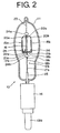
- Fig. 2 is a partly broken right-side view of the electric lamp of Fig. 1.
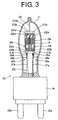
- Fig. 3 is a partly broken rear view of the electric lamp of Fig. 1.
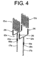
- Fig. 4 is a perspective view indicating the connection between the filaments and the inner electrodes.
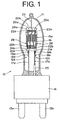
- Fig. 1 is a partly broken front view indicating a structure of an electric lamp of the invention
- Fig. 2 is a partly broken right-side view of the electric lamp of Fig. 1
- Fig. 3 is a partly broken rear view of the electric lamp of Fig. 1.
- an electric lamp 10 is composed of a light-transmitting bulb 11, a bulb base 14 equipped with a pair of inner terminals 12a,12b and a pair of outer terminals 13a,13b, and linear light-emitting means extended between the inner terminals 12a and 12b.
- the linear light-emitting means of the electric lamp 10 is composed of two filaments 15a,15b connected in parallel.
- the filaments 15a,15b are disposed oppositely to each other and shielded from each other with a light transmitting shielding plate 16.
- Fig. 4 is a perspective view indicating the connection between the filaments 15a,15b and the inner terminals 12a,12b in the electric lamp 10. Fig. 4 illustrates only the filaments 15a,15b and inner terminals 12a,12b in the electric lamp.
- the inner terminal 12a is composed of an electrode pole 17a and an auxiliary electrode pole 18a fixed to the electrode pole 17a with a wire 19a.
- the inner terminal 12b is composed of an electrode pole 17b and an auxiliary electrode pole 18b fixed to the electrode pole 17a with a wire 19b.
- the filament 15a is extended between the electrode poles 17a and 17b, and the filament 15b is extended between the auxiliary electrode poles 18a and 18b.
- the linear light-emitting means of the electric lamp 10 is composed of two filaments 15a,15b connected in parallel and extended between the inner terminals 12a,12b.
- Each of the filaments 15a,15b, electrode poles 17a,17b, auxiliary electrode poles 18a,18b, and wires 19a,19b is made of, for example, tungsten.
- each of the top and bottom of the filament 15a is supported by the three wires 20a and the two wires 21a.
- each of the top and bottom of the filament 15b is supported by the three wires 20b and two wires 21b.
- each of the top and bottom of the light-transmitting shielding plate 16 placed between the filaments 15a and 15b is supported by the two wires 22a and two wires 22b.
- the top of the wire 20a, wire 20b and wire 22a are insulated from each other and each is fixed to a upper supporting glass 24a.
- the bottom of the wire 21a, wire 21b and wire 22b are insulated from each other and each is fixed to a lower supporting glass 24b.
- Each of the inner terminals 12a,12b is fixed to the lower supporting glass 24b through the electrode pole and auxiliary electrode pole.
- the supporting pole 23 supports the supporting glass 24a,24b. Further, the top of the supporting pole 23 is placed in the indented area of the glass bulb 11 and keeps the electrode poles 17a,17b from deformation due to outer vibration of the electric lamp.
- a sleeve glass 25 is placed to cover the base side portion 14 of the electrode pole 17b.
- the sleeve glass 25 serves to obviate shortage caused by electric contact between the electrode poles 17a and 17b through a filament which has dropped down onto the base 14 from the broken filament.
- the inner terminal 12a connects with the outer terminal 13a in the inside of the base 14, while the inner terminal 12b connects with the outer terminal 13b in the inside of the base 14.
- both of the two filaments 15a and 15b extended between the inner terminals 12a and 12b emit light at the same time. Since both filaments are caused to emit light simultaneously, one filament continues to emit light when another filament breaks down to cease light emitting and illumination trouble caused by the filament breakage can be minimized.
- the light-transmitting shielding plate 16 arranged in the lamp between the filaments 15a and 15b is described.
- one filament continues to emit light when another filament breaks down to cease light emitting. If there is not placed the shielding plate 16 between the two filaments 15a and 15b, one filament breaks down simultaneously when another filament breaks down. It is understood that a vapor of material (e.g., tungsten) of one filament produced when the filament breaks down moves to become into contact with another filament and electric discharge takes place on the latter filament and that the electric discharge on the latter filament causes temperature elevation of the filament, resulting in the breakage of the filament.
- the shielding plate 16 serves to keep the light-emitting filament from the contact with the vapor produced from the broken filament.
- the light-transmitting shielding plate is arranged to shield all imaginary lines connecting the filaments 15a,15b disposed oppositely to each other. In other words, it is preferred that all of the imaginary lines connecting an optionally selected site of one filament and an optionally selected site of another filament are shielded by the light-transmitting shielding plate 16. Under this arrangement, the vapor produced from the broken filament is effectively kept from another filament. It is noted that a fixing area 26 (a portion extended from each of the filament 15a,15b and wound around the electrode pole and auxiliary electrode pole) merely serves to fix each filament to the electrode pole and auxiliary electrode pole and is not included in the "filament" defined in the specification.
- the light-transmitting shielding plate 16 has a length (length in the longitudinal direction of the bulb 11) of 26 mm, a width of 20 mm, and a thickness of 1.5 mm. There is no limitation with respect to the thickness of the light-transmitting shielding plate 16, but the thickness is in the range of 0.1 to 5 mm, from the view point of the practical use.
- Representative examples of the material of the light-transmitting shielding plate 16 include glass and light-transmitting alumina.
- the glasses include quartz glass, hard glass, and Vycor glass.
- the light-transmitting shielding glass 16 of the electric lamp 10 in Figures 1 to 3 is made of quartz glass.
- the light-transmitting shielding plate 16 may have micro-pores therein under such condition that transmission of the vapor from the filament is inhibited.
- the light-transmitting shielding plate is preferably heated under reduced pressure for removing volatile components such as water on or in the plate before the plate is placed in the bulb 11.
- the linear light-emitting means extended between the inner terminals of the lamp of the invention can be composed of three or more filaments arranged in parallel.
- at least one filament and other filament(s) are disposed oppositely to each other and shielded by the light-transmitting shielding plate.
- each filament is preferably shielded from adjacent filaments by a shielding plate.
- each of the filaments 15a,15b has an electric capacity of 1,000 W.
- one filament When two filaments are employed, one filament preferably has an electric capacity lower than an electric capacity of another filament. If the two filaments have different electric capacities, the filament having a lower electric capacity tends to break down earlier than the filament having a higher electric capacity. Therefore, it scarcely happens that both filaments break down simultaneously or successively due to end of their life times.
- the electric capacity of the filament can be controlled by adjusting thickness of filament, coiling length of filament and the pitch of coiling of filament.
- the two filaments of the lamp 10 in Figures 1 to 3 can be so adjusted that one filament has an electric capacity of 1,200 W and another filament has an electric capacity of 800 W.
- the electric capacity of the filament having a lower electric capacity is extremely lower than the electric capacity of the filament having a higher electric capacity, the filament having a lower electric capacity tends to break down in a short working period of time. Accordingly, it is preferred that the electric capacity of the filament having a lower electric capacity has an electric capacity of 30% or higher based on the electric capacity of the filament having a higher electric capacity.
- one filament has a color temperature higher than a color temperature of another filament so that the two filaments do not break down simultaneously or successively due to end of their life times.
- the color temperature of the filament can be controlled by thickness of filament, coiling length of filament and the pitch of coiling of filament.
- the two filaments of the lamp 10 in Figures 1 to 3 can be so adjusted that one filament has a color temperature of 3,150 K and another filament has a color temperature of 3,250 K.
- the difference of color temperature between two filaments is adjusted to be lower than 100 K.
- the bulb of the electric lamp preferably contains a halogen gas or a halogen compound gas.
- An electric lamp containing a halogen gas or a halogen compound gas is generally named a halogen lamp.
- the bulb and filaments are kept from blackening by incorporating a halogen gas or a halogen compound gas.
- a nitrogen gas, an oxygen gas, or an argon gas can be incorporated into the bulb.
- the electric lamp 10 in Figures 1 to 3 contains, for example, gases of halogen compounds (CH 3 Br and CH 2 Cl 2 ), an oxygen gas and a nitrogen gas.
- the electric lamp of the invention has a bulb base (base or cap) which is equipped with a pair of inner terminals and outer terminals.
- the bulb base of the lamp of the invention can be a bipost type base equipped with the outer terminal poles 13a,13b (as is shown in Figures 1 to 3) or a screw base equipped with a pair of outer terminals.
Landscapes
- Non-Portable Lighting Devices Or Systems Thereof (AREA)
Applications Claiming Priority (2)
| Application Number | Priority Date | Filing Date | Title |
|---|---|---|---|
| JP2004056280A JP2005251418A (ja) | 2004-03-01 | 2004-03-01 | 電球 |
| PCT/JP2005/003406 WO2005083747A1 (ja) | 2004-03-01 | 2005-03-01 | 電球 |
Publications (1)
| Publication Number | Publication Date |
|---|---|
| EP1727187A1 true EP1727187A1 (en) | 2006-11-29 |
Family
ID=34908904
Family Applications (1)
| Application Number | Title | Priority Date | Filing Date |
|---|---|---|---|
| EP05719723A Withdrawn EP1727187A1 (en) | 2004-03-01 | 2005-03-01 | Lamp bulb |
Country Status (6)
| Country | Link |
|---|---|
| US (1) | US20070278953A1 (enExample) |
| EP (1) | EP1727187A1 (enExample) |
| JP (1) | JP2005251418A (enExample) |
| KR (1) | KR20060116250A (enExample) |
| CN (1) | CN1977357A (enExample) |
| WO (1) | WO2005083747A1 (enExample) |
Cited By (6)
| Publication number | Priority date | Publication date | Assignee | Title |
|---|---|---|---|---|
| WO2008077756A3 (de) * | 2006-12-21 | 2008-11-27 | Osram Gmbh | Halogenglühlampe |
| RU2548365C1 (ru) * | 2014-02-12 | 2015-04-20 | Владимир Викторович Черниченко | Электрическая лампа накаливания |
| RU2549616C1 (ru) * | 2014-02-12 | 2015-04-27 | Владимир Викторович Черниченко | Электрическая лампа накаливания |
| RU2550336C1 (ru) * | 2014-02-12 | 2015-05-10 | Владимир Викторович Черниченко | Электрическая лампа накаливания |
| RU2559790C1 (ru) * | 2014-02-12 | 2015-08-10 | Владимир Викторович Черниченко | Электрическая лампа накаливания |
| RU2568664C2 (ru) * | 2014-02-12 | 2015-11-20 | Владимир Викторович Черниченко | Электрическая лампа накаливания |
Families Citing this family (4)
| Publication number | Priority date | Publication date | Assignee | Title |
|---|---|---|---|---|
| US8796910B2 (en) | 2008-07-23 | 2014-08-05 | Lg Electronics, Inc. | Halogen lamp comprising bulb and structure to prevent filament parts from contracting each other |
| WO2011150174A1 (en) * | 2010-05-28 | 2011-12-01 | Superior Quartz Products, Inc. | Discharge lamp with self-supporting electrode structures |
| JP5992316B2 (ja) * | 2012-12-18 | 2016-09-14 | 江東電気株式会社 | ハロゲン電球 |
| CN219889363U (zh) | 2023-04-28 | 2023-10-24 | 东莞市米蕾电子科技有限公司 | 一种简易荧光丝幻彩灯泡 |
Family Cites Families (4)
| Publication number | Priority date | Publication date | Assignee | Title |
|---|---|---|---|---|
| US1481680A (en) * | 1921-01-10 | 1924-01-22 | Brindel Clyde | Incandescent lamp |
| US1513407A (en) * | 1921-03-25 | 1924-10-28 | Lombos Arthur Lasslow | Incandescent lamp |
| US4302250A (en) * | 1980-09-08 | 1981-11-24 | Corning Glasss Works | Glass envelopes for tungsten-halogen lamps |
| FR2795232A1 (fr) * | 1999-06-15 | 2000-12-22 | Koninkl Philips Electronics Nv | Lampe pour projecteur muni d'un reflecteur |
-
2004
- 2004-03-01 JP JP2004056280A patent/JP2005251418A/ja active Pending
-
2005
- 2005-03-01 CN CNA2005800139278A patent/CN1977357A/zh active Pending
- 2005-03-01 KR KR1020067020517A patent/KR20060116250A/ko not_active Withdrawn
- 2005-03-01 WO PCT/JP2005/003406 patent/WO2005083747A1/ja not_active Ceased
- 2005-03-01 EP EP05719723A patent/EP1727187A1/en not_active Withdrawn
- 2005-03-01 US US10/591,251 patent/US20070278953A1/en not_active Abandoned
Non-Patent Citations (1)
| Title |
|---|
| See references of WO2005083747A1 * |
Cited By (6)
| Publication number | Priority date | Publication date | Assignee | Title |
|---|---|---|---|---|
| WO2008077756A3 (de) * | 2006-12-21 | 2008-11-27 | Osram Gmbh | Halogenglühlampe |
| RU2548365C1 (ru) * | 2014-02-12 | 2015-04-20 | Владимир Викторович Черниченко | Электрическая лампа накаливания |
| RU2549616C1 (ru) * | 2014-02-12 | 2015-04-27 | Владимир Викторович Черниченко | Электрическая лампа накаливания |
| RU2550336C1 (ru) * | 2014-02-12 | 2015-05-10 | Владимир Викторович Черниченко | Электрическая лампа накаливания |
| RU2559790C1 (ru) * | 2014-02-12 | 2015-08-10 | Владимир Викторович Черниченко | Электрическая лампа накаливания |
| RU2568664C2 (ru) * | 2014-02-12 | 2015-11-20 | Владимир Викторович Черниченко | Электрическая лампа накаливания |
Also Published As
| Publication number | Publication date |
|---|---|
| US20070278953A1 (en) | 2007-12-06 |
| KR20060116250A (ko) | 2006-11-14 |
| WO2005083747A1 (ja) | 2005-09-09 |
| JP2005251418A (ja) | 2005-09-15 |
| CN1977357A (zh) | 2007-06-06 |
| WO2005083747A8 (ja) | 2006-10-19 |
Similar Documents
| Publication | Publication Date | Title |
|---|---|---|
| US4871944A (en) | Compact lighting unit having a convoluted fluorescent lamp with integral mercury-vapor pressure-regulating means, and method of phosphor-coating the convoluted envelope for such a lamp | |
| US20010003411A1 (en) | High-intensity discharge lamp, system for lighting the lamp and lighting appliance using the lamp | |
| EP1727187A1 (en) | Lamp bulb | |
| NL8702086A (nl) | Hogedrukgasontladingslamp en armatuur voorzien van die lamp. | |
| US4754197A (en) | Arc discharge lamp assembly simulating gaslight | |
| US7178944B2 (en) | Lighting apparatus | |
| EP0994500A1 (en) | Mercury-Xenon high-pressure discharge lamp, illumination device and image projection display system using the lamp | |
| KR20040010190A (ko) | 전구형 형광램프 및 조명기구 | |
| CA1280460C (en) | Multiple discharge device hid lamp with preferential starting | |
| US4417176A (en) | Compact fluorescent lamp | |
| US7358676B2 (en) | Fluorescent light source | |
| US7045946B2 (en) | Fluorescent lamp | |
| JP4099702B2 (ja) | 電球形蛍光ランプおよび照明装置 | |
| US7012373B2 (en) | Electronic energy-saving fluorescent lamp of ultra-short chayote-shaped compact type | |
| US20050218808A1 (en) | CCFL tube device | |
| US6789919B2 (en) | Circular fluorescent lamp unit and lighting apparatus | |
| JP2003507876A (ja) | 低圧水銀蒸気放電ランプ | |
| JP4196668B2 (ja) | 電球形蛍光ランプ及び照明器具 | |
| JPH06140003A (ja) | 高圧放電灯 | |
| JP4221654B2 (ja) | 電球形蛍光ランプおよび照明装置 | |
| CN101147230B (zh) | 用于照明器的偏转部件和附属的照明器 | |
| KR910007969Y1 (ko) | 형광등용 스타트램프의 바이메탈 필라멘트 | |
| KR20140095211A (ko) | 형광 램프 | |
| US20020158566A1 (en) | Low-pressure mercury vapor discharge lamp | |
| CA1141417A (en) | Screw-in type lighting unit having a convoluted tridimensional fluorescent lamp |
Legal Events
| Date | Code | Title | Description |
|---|---|---|---|
| PUAI | Public reference made under article 153(3) epc to a published international application that has entered the european phase |
Free format text: ORIGINAL CODE: 0009012 |
|
| 17P | Request for examination filed |
Effective date: 20060914 |
|
| AK | Designated contracting states |
Kind code of ref document: A1 Designated state(s): AT BE BG CH CY CZ DE DK EE ES FI FR GB GR HU IE IS IT LI LT LU MC NL PL PT RO SE SI SK TR |
|
| AX | Request for extension of the european patent |
Extension state: AL BA HR LV MK YU |
|
| RIN1 | Information on inventor provided before grant (corrected) |
Inventor name: MAEDA, GO Inventor name: KAMEYA, TAKAYUKI Inventor name: HAGIWARA, SEISHIROU |
|
| RIN1 | Information on inventor provided before grant (corrected) |
Inventor name: MAEDA, GO Inventor name: KAMEYA, TAKAYUKI Inventor name: HAGIWARA, SEISHIROU |
|
| STAA | Information on the status of an ep patent application or granted ep patent |
Free format text: STATUS: THE APPLICATION HAS BEEN WITHDRAWN |
|
| 18W | Application withdrawn |
Effective date: 20090122 |