EP1726774A2 - Elements glissants pour un araignée ou un elevateur fournissant une répartition égalisée des charges - Google Patents
Elements glissants pour un araignée ou un elevateur fournissant une répartition égalisée des charges Download PDFInfo
- Publication number
- EP1726774A2 EP1726774A2 EP06270046A EP06270046A EP1726774A2 EP 1726774 A2 EP1726774 A2 EP 1726774A2 EP 06270046 A EP06270046 A EP 06270046A EP 06270046 A EP06270046 A EP 06270046A EP 1726774 A2 EP1726774 A2 EP 1726774A2
- Authority
- EP
- European Patent Office
- Prior art keywords
- tubular
- die
- bowl
- gripping
- gripping member
- Prior art date
- Legal status (The legal status is an assumption and is not a legal conclusion. Google has not performed a legal analysis and makes no representation as to the accuracy of the status listed.)
- Granted
Links
- 241000239290 Araneae Species 0.000 title claims description 49
- 238000000034 method Methods 0.000 claims description 10
- 230000008878 coupling Effects 0.000 claims description 4
- 238000010168 coupling process Methods 0.000 claims description 4
- 238000005859 coupling reaction Methods 0.000 claims description 4
- 238000005553 drilling Methods 0.000 description 2
- 239000002184 metal Substances 0.000 description 2
- 238000004458 analytical method Methods 0.000 description 1
- 230000001419 dependent effect Effects 0.000 description 1
- 230000000694 effects Effects 0.000 description 1
- 230000003993 interaction Effects 0.000 description 1
- 230000001788 irregular Effects 0.000 description 1
- 238000004519 manufacturing process Methods 0.000 description 1
- 230000013011 mating Effects 0.000 description 1
- 230000035515 penetration Effects 0.000 description 1
- 230000000717 retained effect Effects 0.000 description 1
Images


Classifications
-
- E—FIXED CONSTRUCTIONS
- E21—EARTH OR ROCK DRILLING; MINING
- E21B—EARTH OR ROCK DRILLING; OBTAINING OIL, GAS, WATER, SOLUBLE OR MELTABLE MATERIALS OR A SLURRY OF MINERALS FROM WELLS
- E21B19/00—Handling rods, casings, tubes or the like outside the borehole, e.g. in the derrick; Apparatus for feeding the rods or cables
- E21B19/02—Rod or cable suspensions
- E21B19/06—Elevators, i.e. rod- or tube-gripping devices
- E21B19/07—Slip-type elevators
Definitions
- Embodiments of the present invention generally relate to an apparatus for supporting a tubular.
- an elevator or a spider includes a plurality of slips circumferentially surrounding the exterior of the pipe string.
- the slips are housed in what is commonly referred to as a "bowl".
- the bowl is regarded to be the surfaces on the inner bore of the spider, an elevator, or another tubular-supporting device.
- the inner sides of the slips usually carry teeth formed on hard metal dies for engaging the pipe string.
- the exterior surface of the slips and the interior surface of the bowl have opposing engaging surfaces which are inclined and downwardly converging.
- the inclined surfaces allow the slip to move vertically and radially relative to the bowl.
- the inclined surfaces serve as wedging surfaces for engaging the slip with the pipe.
- the slips will move downward with respect to the bowl.
- the inclined surfaces urge the slips to move radially inward to engage the pipe.
- this feature of the spider is referred to as "self tightening.”
- the slips are designed to prohibit release of the pipe string until the pipe load is supported and lifted by another device.
- the spider In the makeup or breakup of pipe strings, the spider is typically used for securing the pipe string in the wellbore at a rig floor. Additionally, an elevator suspended from a rig hook includes a separately operable set of slips and is used in tandem with the spider.
- the elevator may include a self-tightening feature similar to the one in the spider.
- the spider holds the tubular string at an axial position while the elevator positions a new pipe section above the pipe string for connection. After completing the connection, the elevator pulls up on and bears the weight of the string thereby releasing the pipe string from the slips of the spider therebelow. The elevator then lowers the pipe string into the wellbore. Before the pipe string is released from the elevator, the spider is allowed to engage the pipe string again to support the pipe string. After the weight of the pipe string is switched back to the spider, the elevator releases the pipe string and continues the makeup or break out process for the next joint.
- Slips are also historically used in a wellbore to retain the weight of tubular strings and aid in locating and fixing tubular strings at a predetermined location in a wellbore.
- Packers, liner hangers and plugs all use slips and cones, the cones providing an angled surface for the slip members to become wedged between a wellbore wall and the tubular string and ensuring that the weight of the string is supported.
- Embodiments of the present invention generally relate to an apparatus for supporting a tubular that more evenly distributes stress along the contact length of a tubular than prior art designs.
- an apparatus for supporting a tubular is provided.
- the apparatus includes a slip member movable along a supporting surface in order to wedge the slip member between the tubular to be retained and the supporting surface.
- the contact surface between the slip member and the supporting surface is designed whereby an upper portion of the gripping surface of the slip member will initially contact the tubular, thereby distributing the forces generated by the weight of the tubular in a more effective manner.
- an apparatus for supporting a tubular in another embodiment, includes a bowl having a longitudinal opening extending therethrough and an inner surface for receiving a gripping member.
- the inner surface of the bowl is inclined at an angle A b relative to a longitudinal axis of the tubular.
- the gripping member is movable along the surface of the bowl for engaging the tubular and has an outer surface inclined at an angle A s relative to the longitudinal axis of the tubular. A s is greater than A b .
- an apparatus for supporting a tubular in another embodiment, includes a bowl having a longitudinal opening extending therethrough and an inner surface for receiving a gripping member.
- the gripping member is movable along the surface of the bowl for engaging the tubular.
- the gripping member includes a die having teeth for engaging the tubular and disposed along a length of the gripping member. The die has a tapered thickness.
- an apparatus for supporting a tubular in another embodiment, includes a bowl having a longitudinal opening extending therethrough and an inner surface for receiving a gripping member.
- the gripping member is movable along the surface of the bowl for engaging the tubular.
- the apparatus further includes means for distributing stress substantially evenly along a length of the tubular in contact with the gripping member.
- an apparatus for supporting a tubular includes at least one slip moveable along a surface of a support and having a first surface and an opposite gripping surface.
- the apparatus further includes a die having teeth for engaging the tubular, the die disposed in a slot formed in the gripping surface.
- the apparatus further includes the support, wherein: the first surface and the support surface are configured so that the gripping member will wedge between the support and the tubular, and the die and the slot are configured so that the die may rotate within the slot to facilitate engagement with the tubular.
- a method for manufacturing an apparatus for supporting a tubular includes providing the apparatus, including: at least one slip moveable along a surface of a support and having a first surface and an opposite gripping surface for engaging the tubular; and the support, wherein: the first surface and the support surface are configured so that the gripping member will wedge between the support and the tubular, and the apparatus is configured so that an upper portion of the gripping surface will engage the tubular before the remainder of the gripping surface engages the tubular.
- the method further includes using the apparatus as a spider, elevator, liner hanger, plug, or gripping apparatus of a top drive casing make up unit.
- Figure 1 is an isometric view of a gripping apparatus, according to one embodiment of the present invention.
- Figure 1A is an isometric view of one of the slips used in the spider of Figure 1.
- Figure 2 is a simplified sectional view of the spider of Figure 1.
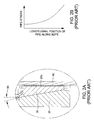
- Figures 2A and 2C are details of Figure 2 showing inclination angles of each slip and the bowl in a prior art spider and a spider according to one embodiment of the present invention, respectively.
- Figures 2B and 2D are plots of pipe stress versus longitudinal position of the tubular along the slips in a prior art spider and a spider according to one embodiment of the present invention, respectively.
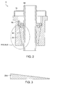
- Figure 3 is a sectional view of a die according to an alternative embodiment of the present invention.
- Figures 4A and 4B are various views of another alternative embodiment of the present invention.
- Figures 4A is an isometric view of a slip.
- Figure 4B is an isometric view of a bowl section.
- Figure 5 is a top view of a slip according to another alternative embodiment of the present invention.
- Figure 5A is a top view of a die, a plurality of which is received by the slip.
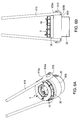
- Figure 6A is an isometric view of the spider of Figure 1 fitted with an elevator ring and bails for use with a top drive system or other hoisting device.
- Figure 6B is a front view of Figure 6A.
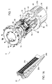
- FIG. 1 is an isometric view of a gripping apparatus, according to one embodiment of the present invention.
- the gripping apparatus is a flush mounted spider 5 disposable within a rotary table (not shown).
- the spider 5 may be fitted for use in an elevator.
- embodiments of the invention can be utilized in any well known apparatus that is dependent upon a slip member and a supporting surface, like a cone to retain the weight of a tubular string in a wellbore or at the surface of a well.
- embodiments of the invention can be utilized in a top drive system used for drilling with casing. More specifically, embodiments can be used in a top drive casing make up system that grips the casing either by the inside or outside of the casing.
- the spider 5 includes a body, i.e. bowl 25, for housing one or more gripping members, i.e. slips 20, and a cover assembly 15 for the bowl 25.
- the bowl 25 of the spider 5 is formed by pivotally coupling two sections 25a,b using one or more connectors, preferably hinges 35 formed on both sides of each body section, used to couple the two body sections together.
- the body sections 25a,b may be hinged on one side and selectively locked together on the other side.
- a hole is formed through each hinge 35 to accommodate a pin 40 (only one shown) to couple the bowl sections 25a,b together.
- the bowl 25 of the spider 5 includes one or more guide keys 45 (only one shown) for guiding the axial movement of a slip 20.
- Each guide key 45 mates with a guide slot 46 formed longitudinally on the outer surface of the slip 20. In this manner, the guide key 45 may maintain the path of a moving slip 20. Furthermore, the guide key 45 prevents the slip 20 from rotating in the bowl 25 as it moves axially along the bowl 25. Because the slip 20 cannot rotate within the bowl 25, the spider 5 may be used as a back up torque source during the make up or break out of pipe connections.
- a flange 30 is formed on an upper portion of each of the bowl sections 25a,b for connection to the cover assembly 15.
- An abutment i.e. block 50 (only one shown), is attached to a lower portion of each flange 30 of the bowl sections 25a,b.
- the blocks 50 are designed to mate with slots formed in the rotary table (not shown). The blocks 50 allow torque to be reacted between the spider 5 and the rotary table. As a result, the spider 5 is prevented from rotating inside the rotary table when it is used as a back up torque source during the make up or break out of pipe connections.
- the spider 5 includes a leveling ring 55 for coupling the slips 20 together and synchronizing their vertical movement.
- the leveling ring 55 includes one or more guide bearings 60 extending radially from the leveling ring 55.
- the leveling ring 55 has four guide bearings 60 (three are shown) equally spaced apart around the circumference of the leveling ring 55.
- For each guide bearing 60 there is a corresponding guide track 65 formed on the inner wall of the upper portion of the bowl 25.
- the guide track 65 directs the vertical movement of the leveling ring 55 and prevents the leveling ring 55 from rotating.
- the guide track 65 helps to center a tubular 90 (see Figure 2) inside the spider 5 and provides better contact between the slips 20 and the tubular.
- a piston and cylinder assembly 70 is attached below each of the guide bearings 60 and is associated with a respective slip 20.
- the slips 20 will be disposed on a surface of the bowl 25 and will be moved along the bowl 25 by the piston and cylinder assembly 70.
- An outer surface of each of the slips 20 is inclined and includes a guide slot 46 for mating with the respective guide key 45 of the bowl 25.
- the piston and cylinder assembly 70 may lower the slip 20 along the incline of the bowl 25.
- the incline directs the slip 20 radially toward the center of the spider 5, thereby moving the slip 20 into contact with the tubular 90.
- the piston and cylinder 70 is actuated to move the slip 20 up the incline and away from the pipe.
- the cover assembly 15 includes two separate sections, each attached above a respective bowl section 25a,b.
- the sectioned cover assembly 15 allows the bowl sections 25a,b of the spider 10 to open and close without removing the cover assembly 15.
- the sections of the cover assembly 15 form a hole whose center coincides with the center of the body 10.
- the cover assembly 15 includes one or more guide rollers 80 to facilitate the movement and centering of the tubular 90 in the spider 5.
- the guide rollers 80 are attached below the cover assembly 15 and are adjustable.
- the guide rollers 80 may be adjusted radially to accommodate tubulars of various sizes.
- an adapter plate (not shown) having a hole sized for a particular tubular may be attached to each section of the cover assembly 15 to facilitate the movement and centering of the tubular.
- Figure 1A is an isometric view of one of the slips 20 used in the spider 5.
- the slip 20 includes an outer member 20a having an inclined outer surface which corresponds with an inclined inner surface of the bowl 25. Coupled to the outer member 20a is an inner member 20b which has a curved inner surface to accommodate the tubular 90.
- One or more hardened metal dies 20c having teeth for engaging the tubular 90 are coupled to an inner surface of the inner member 20b.
- the spider 5 is flush mounted in rotary table.
- the guide rollers 80 are adjusted to accommodate the incoming tubular.
- the slips 20 are in a retracted position on the bowl 25.
- the piston and cylinder assembly 70 is actuated to move the slips 20 down along the incline of the bowl 25.
- the slips 20 are guided by the guide keys 45 disposed on the bowl 25.
- the incline causes the slips 20 to move radially toward the tubular 90 and contact the tubular.
- the make up/break up operation is performed.
- the piston and cylinder assembly 70 is actuated to move the slips 20 up along the incline, thereby causing the slips 20 to move radially away from the tubular.
- Figure 2 is a simplified sectional view of the spider 5.
- the slips 20 of spider 5 are shown engaging the tubular 90 which is part of a string of tubulars.
- Figures 2A and 2C are details of Figure 2 showing inclination angles, relative to a longitudinal axis of the tubular 90, of each slip 20 and the bowl 25 in a prior art spider and the spider 5, respectively.
- Figures 2B and 2D are plots of pipe stress versus longitudinal position of the tubular 90 along the slips 20 in a prior art spider and the spider 5, respectively.
- Figure 2A shows that an inclination angle 95 is the same for both the slips and the bowl.
- Figure 2B shows the resulting stress distribution along the length of the pipe in contact with the slips.
- Engineering calculations and finite element analysis show that the stress is concentrated on the lower section of the slips that are engaged with the tubular. This stress concentration is caused by the combination of radial stress that is generated by the slips engaging the tubular with axial stresses produced by the weight of the string.
- the stress distribution is non-uniform and the stress increases towards a lower end of the tubular 90.
- Figure 2C shows a design that more evenly distributes the stress distribution along the length of the tubular 90 in contact with the dies 20c of the slips 20.
- Each slip 20 has an inclination angle 95s that is greater than an inclination angle 95b of the bowl.
- the difference between slip angle 95s and bowl angle 95b is less than 1 degree, more preferably less than one-quarter of a degree, and most preferably less than or equal to about one-eighth of a degree. This difference results in an upper portion of each of the dies 20c contacting the tubular 90 before the rest of each of the dies.
- the weight of the tubular 90 will cause the upper portions of the dies 20c to locally deform or penetrate the outer surface of the tubular, thereby allowing the lower portions of the dies 20c to contact the tubular.
- This penetration causes more of the radial force, generated by the interaction of the slips 20 with the bowl 25, to be exerted on the upper portion of the tubular 90 while allowing the tensile force, generated by the weight of the string, to be exerted on the lower portion of the tubular 90.
- Figure 2D shows the resulting stress distribution on the pipe is uniform or substantially uniform and the stress is substantially less than the maximum stress of the prior art configuration. The result is that for a given tubular 90, the spider 5 may handle more weight or a longer string of tubulars before crushing the tubular than the prior art design.
- an outer surface of each slip 20 may be curved instead of inclined so that an upper portion of each of the dies 20d contacting the tubular 90 before the rest of each of the dies 20d, thereby equally or substantially equally distributing the stress along the tubular 90.
- the outer surface is concave.
- Figure 3 is a sectional view of a die 20d according to an alternative embodiment of the present invention.
- the slip angle 95s being greater than the bowl angle 95b
- the thickness of the die 20d increases towards an upper end of each of the slips 20.
- using the dies 20d, in place of the mismatched angles 95b,s would result in an upper portion of each of the dies 20d contacting the tubular 90 before the rest of each of the dies 20d, thereby equally or substantially equally distributing the stress along the tubular 90.
- Figures 4A and 4B are various views of another alternative embodiment of the present invention.
- Figures 4A is an isometric view of a slip 420.
- Figure 4B is an isometric view of a bowl section 425.
- the slip 420 includes an outer member 420a. Coupled to the outer member 420a is an inner member 420b which has a curved inner surface (not shown, see member 20b shown in Figure 1A) to accommodate the tubular 90. Dies of the slip 420 are also not shown; however, they may be similar to the dies 20c shown in Figure 1A.
- the bowl section 425 includes a plurality of slots 402 formed in an inner surface thereof, each of which will receive a slip 420.
- the outer member 420a has an inclined outer surface which corresponds with an inclined facing surface of each of the slots 402.
- the outer surface of the outer member 420a has an inclination angle 495s that is greater than an inclination angle 495b of the slots 402, thereby equally or substantially equally distributing the stress along the tubular 90.
- the difference between this embodiment and that of Figures 1 and 2C is that the outer surface of the outer member 420a is flat or substantially flat along a circumferential direction because of the slots 402, which are also flat or substantially flat in a circumferential direction, whereas the outer surface of the outer member 20a is circumferentially curved to accommodate the circumferential curvature of the bowl 25.
- the height of the die teeth may vary along the length of the die so that the teeth on an upper portion of each of the dies contact the tubular before the teeth on the rest of each of the dies, thereby equally or substantially equally distributing the stress along the tubular.
- Figure 5 is a top view of a slip 520 according to another alternative embodiment of the present invention.
- Figure 5A is a top view of a die 520c, a plurality of which is received by the slip 520.
- Formed in an inner surface of the inner member 520b is a plurality of slots 520d.
- Received in each of the slots 520d is one of the dies 520c.
- An inner surface of each die 520c is rounded so that the dies may rotate slightly within the slots 520d to improve gripping of the tubular 90, especially for tubulars 90 with irregular cross sections.
- a facing surface of each slot 520d may be rounded instead of the inner surface of each die 520c.
- This rounded die 520c or slip slot 520d embodiment may be implemented in the embodiments shown in Figures 1 and 2C, 3, and 4.
- Figure 6A is an isometric view of the spider 5 of Figure 1 fitted with an elevator ring 605 and bails 615 for use with a top drive system (not shown) or other hoisting device.
- Figure 6B is a front view of Figure 6A.
- the blocks 50 have been removed from the flanges 30.
- the elevator ring slides over the bowl 25 from the bottom side until it abuts the flange 30.
- the elevator ring has a pair of upper 605a and lower 605b brackets formed thereon. Each bracket has a hole for receiving a connector, such as a bolt.
- the upper brackets 605a are formed to each receive a loop 615a of each of the bails 615.
- a "J" shaped bracket 610 is then coupled to each pair of upper 605a and lower 605b brackets by bolts to secure each loop 615a in place.
- the bails 615 are then attached to a body of a top drive system, traveling block, or other hoisting device.
Landscapes
- Engineering & Computer Science (AREA)
- Geology (AREA)
- Mining & Mineral Resources (AREA)
- Life Sciences & Earth Sciences (AREA)
- General Life Sciences & Earth Sciences (AREA)
- Fluid Mechanics (AREA)
- Environmental & Geological Engineering (AREA)
- Physics & Mathematics (AREA)
- Mechanical Engineering (AREA)
- Geochemistry & Mineralogy (AREA)
- Earth Drilling (AREA)
- Bending Of Plates, Rods, And Pipes (AREA)
- Lift-Guide Devices, And Elevator Ropes And Cables (AREA)
- Shaping Of Tube Ends By Bending Or Straightening (AREA)
- Manufacturing Of Tubular Articles Or Embedded Moulded Articles (AREA)
- Load-Engaging Elements For Cranes (AREA)
- Metal Extraction Processes (AREA)
Priority Applications (1)
| Application Number | Priority Date | Filing Date | Title |
|---|---|---|---|
| EP20100174610 EP2256286A3 (fr) | 2005-05-12 | 2006-05-11 | Elements glissants pour un araignée ou un elevateur fournissant une répartition égalisée des charges |
Applications Claiming Priority (2)
| Application Number | Priority Date | Filing Date | Title |
|---|---|---|---|
| US68020405P | 2005-05-12 | 2005-05-12 | |
| US68919905P | 2005-06-09 | 2005-06-09 |
Related Child Applications (1)
| Application Number | Title | Priority Date | Filing Date |
|---|---|---|---|
| EP10174610.5 Division-Into | 2010-08-31 |
Publications (3)
| Publication Number | Publication Date |
|---|---|
| EP1726774A2 true EP1726774A2 (fr) | 2006-11-29 |
| EP1726774A3 EP1726774A3 (fr) | 2006-12-20 |
| EP1726774B1 EP1726774B1 (fr) | 2012-04-18 |
Family
ID=36951553
Family Applications (2)
| Application Number | Title | Priority Date | Filing Date |
|---|---|---|---|
| EP20100174610 Withdrawn EP2256286A3 (fr) | 2005-05-12 | 2006-05-11 | Elements glissants pour un araignée ou un elevateur fournissant une répartition égalisée des charges |
| EP06270046A Expired - Fee Related EP1726774B1 (fr) | 2005-05-12 | 2006-05-11 | Elements glissants pour un araignée ou un elevateur fournissant une répartition égalisée des charges |
Family Applications Before (1)
| Application Number | Title | Priority Date | Filing Date |
|---|---|---|---|
| EP20100174610 Withdrawn EP2256286A3 (fr) | 2005-05-12 | 2006-05-11 | Elements glissants pour un araignée ou un elevateur fournissant une répartition égalisée des charges |
Country Status (3)
| Country | Link |
|---|---|
| US (2) | US7686088B2 (fr) |
| EP (2) | EP2256286A3 (fr) |
| CA (3) | CA2702189C (fr) |
Cited By (5)
| Publication number | Priority date | Publication date | Assignee | Title |
|---|---|---|---|---|
| WO2011060773A3 (fr) * | 2009-11-23 | 2012-03-01 | Blohm + Voss Repair Gmbh | Dispositif pour fixer des tubes de diamètre différent |
| CN102877585A (zh) * | 2011-07-13 | 2013-01-16 | 发特泽公开股份有限公司 | 用于固定拉动元件尤其是拉动缆索的装置 |
| EP2551530A1 (fr) * | 2011-07-25 | 2013-01-30 | Blohm + Voss Repair GmbH | Dispositif destiné à la manipulation de tuyaux |
| EP2930298A1 (fr) * | 2014-03-28 | 2015-10-14 | Weatherford/Lamb Inc. | Ascenseur pivotant |
| CN102900383B (zh) * | 2011-07-25 | 2016-11-30 | 布洛姆福斯石油工具有限公司 | 用于操纵管的装置 |
Families Citing this family (21)
| Publication number | Priority date | Publication date | Assignee | Title |
|---|---|---|---|---|
| US7686088B2 (en) * | 2005-05-12 | 2010-03-30 | Weatherford/Lamb, Inc. | Equalized load distribution slips for spider and elevator |
| US20080264648A1 (en) * | 2007-04-27 | 2008-10-30 | Bernd-Georg Pietras | Apparatus and methods for tubular makeup interlock |
| CN103277056B (zh) * | 2007-04-28 | 2016-04-06 | 国民油井华高有限合伙公司 | 用于在钻机中下送管件的下送设备 |
| US7926577B2 (en) * | 2008-09-10 | 2011-04-19 | Weatherford/Lamb, Inc. | Methods and apparatus for supporting tubulars |
| US9181763B2 (en) | 2010-03-24 | 2015-11-10 | 2M TEK, Inc. | Apparatus for supporting or handling tubulars |
| US8240372B2 (en) * | 2010-04-15 | 2012-08-14 | Premiere, Inc. | Fluid power conducting swivel |
| US8757269B2 (en) * | 2010-07-22 | 2014-06-24 | Oceaneering International, Inc. | Clamp for a well tubular |
| CN102094585A (zh) * | 2010-12-14 | 2011-06-15 | 张家港市国锋探矿机械有限公司 | 岩心钻机液压卡盘 |
| WO2012100019A1 (fr) | 2011-01-21 | 2012-07-26 | 2M-Tek, Inc. | Dispositif et procédé pour descendre des tubulaires |
| WO2012151147A2 (fr) * | 2011-05-01 | 2012-11-08 | Frank's Casing Crew And Rental Tool, Inc. | Collier à coins flottant |
| CN103216199B (zh) * | 2013-04-10 | 2014-12-31 | 宝鸡石油机械有限责任公司 | 全自动液压卡瓦 |
| CN103216200B (zh) * | 2013-05-10 | 2015-07-01 | 河南龙腾新型钻具制造有限公司 | 一种钻机的多功能夹具 |
| DE102014005234B4 (de) * | 2013-07-18 | 2015-12-03 | Blohm + Voss Oil Tools Gmbh | Vorrichtung zum Halten von Rohren oder Stangen |
| WO2015089213A1 (fr) * | 2013-12-10 | 2015-06-18 | Frank's International, Inc. | Appareil de préhension tubulaire avec cuve mobile |
| US10774600B2 (en) | 2016-08-19 | 2020-09-15 | Weatherford Technology Holdings, Llc | Slip monitor and control |
| IT201700027125A1 (it) * | 2017-03-13 | 2018-09-13 | F Lli Righini S R L | Dispositivo di presa |
| CN108979565A (zh) * | 2017-06-01 | 2018-12-11 | 南京理工大学 | 一种轴径合一式卡瓦 |
| US10557319B2 (en) * | 2017-08-22 | 2020-02-11 | Micheal Allen DANIELS | Wedged camp assembly |
| US10385632B1 (en) * | 2018-04-20 | 2019-08-20 | Drawworks, L.P. | Casing grapple |
| US11345005B2 (en) * | 2019-01-11 | 2022-05-31 | William Colburn | Split nut valve seat puller |
| US11643885B2 (en) | 2021-03-29 | 2023-05-09 | Weatherford Technology Holdings, Llc | Tubular gripping apparatus |
Family Cites Families (79)
| Publication number | Priority date | Publication date | Assignee | Title |
|---|---|---|---|---|
| US330354A (en) * | 1885-11-10 | Beegee | ||
| US1469894A (en) * | 1921-11-30 | 1923-10-09 | Clem S Clarke | Casing head |
| US1541669A (en) * | 1924-11-10 | 1925-06-09 | Robert B Summers | Casing spider |
| US1794273A (en) * | 1930-02-11 | 1931-02-24 | Lee J Black | Double-tapered slip for rotaries |
| US1983545A (en) | 1930-12-25 | 1934-12-11 | Hazard & Miller | Rotary well drilling apparatus |
| US1938545A (en) * | 1931-09-16 | 1933-12-05 | Standard Oil Co | Dewaxing hydrocarbon oils |
| US2061772A (en) * | 1936-04-04 | 1936-11-24 | George E Mclagan | Slip |
| US2063361A (en) * | 1936-06-02 | 1936-12-08 | Lawrence F Baash | Slip |
| US2298507A (en) * | 1939-10-06 | 1942-10-13 | Arthur J Penick | Elevator |
| US2410589A (en) * | 1942-08-17 | 1946-11-05 | August L Segelhorst | Automatic slip mechanism |
| US2563851A (en) * | 1946-12-02 | 1951-08-14 | Byron Jackson Co | Well pipe elevator |
| US2589159A (en) * | 1948-02-19 | 1952-03-11 | Standard Oil Dev Co | Hold-down slip assembly |
| GB790436A (en) | 1955-05-13 | 1958-02-12 | Exxon Research Engineering Co | Improved tower assembly for purifying liquids |
| US2934148A (en) * | 1957-04-12 | 1960-04-26 | Cameron Iron Works Inc | Multiple zone well completion |
| US3330354A (en) | 1959-01-19 | 1967-07-11 | Brown Oil Tools | Pipe hanger assemblies and methods of running and removing multiple strings in well bores |
| GB915683A (en) * | 1959-02-20 | 1963-01-16 | Web Wilson Oil Tools Inc | Gripping dies |
| US3052943A (en) * | 1959-07-17 | 1962-09-11 | Cameron Iron Works Inc | Wedge-type support |
| US3188708A (en) * | 1962-03-12 | 1965-06-15 | Homer W O'haver | Slip assembly for parallel tubing strings |
| US3334923A (en) * | 1963-07-09 | 1967-08-08 | Fmc Corp | Pipe handling mechanism |
| US3287776A (en) * | 1964-01-13 | 1966-11-29 | Cicero C Brown | Multiple string manual operated elevator |
| US3422506A (en) * | 1967-12-26 | 1969-01-21 | Byron Jackson Inc | Convertible elevator |
| US3579752A (en) * | 1970-04-09 | 1971-05-25 | Cicero C Brown | Automatic rotary slips |
| US3675278A (en) * | 1970-07-30 | 1972-07-11 | Thurman O Powell | Combination elevator and spider |
| US3722603A (en) * | 1971-09-16 | 1973-03-27 | Brown Oil Tools | Well drilling apparatus |
| US3748702A (en) * | 1972-06-15 | 1973-07-31 | C Brown | Automated pipe handling apparatus |
| US4203182A (en) * | 1978-02-13 | 1980-05-20 | Varco International, Inc. | Slip assembly |
| GB2014215B (en) | 1978-02-13 | 1982-04-15 | Varco Int | Slip assembly for supporting well pipe |
| US4332062A (en) * | 1980-02-19 | 1982-06-01 | Bowen Tools, Inc. | Bowl structure |
| US4354706A (en) * | 1980-06-02 | 1982-10-19 | Bilco Tools, Inc. | Dual string elevators |
| US4381584A (en) * | 1980-12-15 | 1983-05-03 | Bilco Tools, Inc. | Dual string spider |
| US4523645A (en) * | 1981-05-26 | 1985-06-18 | Moore Boyd B | Method of and apparatus for moving reeled material into and retrieving it from the upper end of a well bore in the earth's surface |
| US4579379A (en) | 1984-01-11 | 1986-04-01 | Hughes Tool Company | Elevator/spider with improved locking mechanism |
| US4600054A (en) * | 1984-03-30 | 1986-07-15 | Equipment Renewal Company | Tubing hanger assembly |
| US4643259A (en) * | 1984-10-04 | 1987-02-17 | Autobust, Inc. | Hydraulic drill string breakdown and bleed off unit |
| DE3522752A1 (de) * | 1985-06-26 | 1987-01-08 | Hauni Werke Koerber & Co Kg | Verfahren und vorrichtung zum steuern des perforierens von zigaretten |
| US4715456A (en) | 1986-02-24 | 1987-12-29 | Bowen Tools, Inc. | Slips for well pipe |
| US4715458A (en) * | 1986-07-11 | 1987-12-29 | Darko Jorge Lazaneo Dragicevic | Beam balance with unequal arms and didder device |
| US4823919A (en) * | 1986-09-15 | 1989-04-25 | Premiere Casing Services, Inc. | Slip construction for supporting tubular members |
| CA1302391C (fr) * | 1987-10-09 | 1992-06-02 | Keith M. Haney | Languettes pour tubage compact utilise avec machine de forage a entrainement de tete |
| EP0396747A4 (en) | 1988-10-28 | 1991-11-13 | Vsesojuzny Naucho-Issledovatelsky I Proektono-Kronstruktorsky | Pipe-gripping device for rotor of drilling rig |
| FR2658972B1 (fr) | 1990-02-23 | 1992-05-15 | Elf Aquitaine | Dispositif de rechauffage de la colonne de production d'un puits et procede de mise en place des enroulements de rechauffage. |
| US5335756A (en) * | 1992-12-22 | 1994-08-09 | Bilco Tools, Inc. | Slip-type gripping assembly |
| DE4326298A1 (de) | 1993-08-05 | 1995-03-09 | Nordmeyer Kg | Backenklemme für einen mechanischen oder hydraulischen Stangenheber |
| US5595248A (en) * | 1995-08-25 | 1997-01-21 | Den-Con Tool Co. | Pipe alignment apparatus |
| US6378399B1 (en) * | 1997-09-15 | 2002-04-30 | Daniel S. Bangert | Granular particle gripping surface |
| US6279654B1 (en) * | 1996-10-04 | 2001-08-28 | Donald E. Mosing | Method and multi-purpose apparatus for dispensing and circulating fluid in wellbore casing |
| US5848647A (en) * | 1996-11-13 | 1998-12-15 | Frank's Casing Crew & Rental Tools, Inc. | Pipe gripping apparatus |
| US6536520B1 (en) * | 2000-04-17 | 2003-03-25 | Weatherford/Lamb, Inc. | Top drive casing system |
| US7509722B2 (en) * | 1997-09-02 | 2009-03-31 | Weatherford/Lamb, Inc. | Positioning and spinning device |
| DE19814033B4 (de) | 1998-03-30 | 2006-01-05 | Tracto-Technik Paul Schmidt Spezialmaschinen | Bohrgestängeführung und Bohrgerät mit Bohrgestängeführung |
| US6089338A (en) * | 1998-04-03 | 2000-07-18 | Frank's Casing Crew And Rental Tools, Inc. | Flush mounted self aligning spider |
| CA2363178C (fr) * | 1999-03-05 | 2008-06-03 | Varco International, Inc. | Instrument d'assemblage de tuyaux |
| US6192981B1 (en) * | 1999-06-07 | 2001-02-27 | True Turn Machine, Inc. | Coiled tubing hanger assembly |
| US6237684B1 (en) * | 1999-06-11 | 2001-05-29 | Frank's Casing Crewand Rental Tools, Inc. | Pipe string handling apparatus and method |
| CA2284428A1 (fr) | 1999-10-01 | 2001-04-01 | Universe Machine Corporation | Support de tige a coins ameliore |
| GB2355030A (en) | 1999-10-06 | 2001-04-11 | Weatherford Lamb | Bushing for a drilling rig |
| US6264395B1 (en) | 2000-02-04 | 2001-07-24 | Jerry P. Allamon | Slips for drill pipe or other tubular goods |
| US6412554B1 (en) * | 2000-03-14 | 2002-07-02 | Weatherford/Lamb, Inc. | Wellbore circulation system |
| US7325610B2 (en) * | 2000-04-17 | 2008-02-05 | Weatherford/Lamb, Inc. | Methods and apparatus for handling and drilling with tubulars or casing |
| US7296623B2 (en) * | 2000-04-17 | 2007-11-20 | Weatherford/Lamb, Inc. | Methods and apparatus for applying torque and rotation to connections |
| US6644413B2 (en) | 2000-06-02 | 2003-11-11 | Oil & Gas Rental Services, Inc. | Method of landing items at a well location |
| US6364012B1 (en) | 2000-06-02 | 2002-04-02 | Oil & Gas Rental Services, Inc. | Drill pipe handling apparatus |
| US6378614B1 (en) | 2000-06-02 | 2002-04-30 | Oil & Gas Rental Services, Inc. | Method of landing items at a well location |
| US7025147B2 (en) | 2000-06-02 | 2006-04-11 | Oil & Gas Rental Services, Inc. | Apparatus for, and method of, landing items at a well location |
| US6349764B1 (en) | 2000-06-02 | 2002-02-26 | Oil & Gas Rental Services, Inc. | Drilling rig, pipe and support apparatus |
| NO314810B1 (no) | 2001-10-05 | 2003-05-26 | Odfjell Services As | Anordning ved rörstyring |
| US6640939B2 (en) * | 2001-10-09 | 2003-11-04 | David A. Buck | Snubbing unit with improved slip assembly |
| CA2366404A1 (fr) * | 2001-12-21 | 2003-06-21 | Murray L. Dallas | Tambour de glissement, et methode d'utilisation |
| CN100356032C (zh) * | 2002-01-04 | 2007-12-19 | 瓦克I/P公司 | 具有承载环的管子夹持结构 |
| US7134531B2 (en) * | 2002-07-16 | 2006-11-14 | Access Oil Tools, Inc. | Heavy load carry slips and method |
| US6994176B2 (en) * | 2002-07-29 | 2006-02-07 | Weatherford/Lamb, Inc. | Adjustable rotating guides for spider or elevator |
| US6892835B2 (en) * | 2002-07-29 | 2005-05-17 | Weatherford/Lamb, Inc. | Flush mounted spider |
| US6920931B1 (en) * | 2002-12-10 | 2005-07-26 | Frank's Casing Crew And Rental Tools, Inc. | Control line guide |
| WO2004079147A2 (fr) * | 2003-03-05 | 2004-09-16 | Weatherford/Lamb, Inc. | Procede et dispositif de forage avec cuvelage |
| US20040207223A1 (en) * | 2003-04-21 | 2004-10-21 | Bee Robert M. | Pipe die method and apparatus |
| US7032690B2 (en) * | 2003-09-12 | 2006-04-25 | Access Oil Tools, Inc. | Apparatus and method for visually detecting wear to insert bowls, bushings, and spiders |
| US20060102337A1 (en) | 2004-11-12 | 2006-05-18 | Elliott Gregory D | Heavy-load landing string system |
| US7267168B1 (en) * | 2004-09-24 | 2007-09-11 | Sipos David L | Spider with discrete die supports |
| US7686088B2 (en) | 2005-05-12 | 2010-03-30 | Weatherford/Lamb, Inc. | Equalized load distribution slips for spider and elevator |
-
2006
- 2006-05-10 US US11/382,550 patent/US7686088B2/en not_active Expired - Fee Related
- 2006-05-10 CA CA2702189A patent/CA2702189C/fr not_active Expired - Fee Related
- 2006-05-10 CA CA2702187A patent/CA2702187C/fr not_active Expired - Fee Related
- 2006-05-10 CA CA2546033A patent/CA2546033C/fr not_active Expired - Fee Related
- 2006-05-11 EP EP20100174610 patent/EP2256286A3/fr not_active Withdrawn
- 2006-05-11 EP EP06270046A patent/EP1726774B1/fr not_active Expired - Fee Related
-
2010
- 2010-01-15 US US12/688,674 patent/US8020627B2/en not_active Expired - Fee Related
Non-Patent Citations (1)
| Title |
|---|
| None |
Cited By (12)
| Publication number | Priority date | Publication date | Assignee | Title |
|---|---|---|---|---|
| WO2011060773A3 (fr) * | 2009-11-23 | 2012-03-01 | Blohm + Voss Repair Gmbh | Dispositif pour fixer des tubes de diamètre différent |
| CN102695845A (zh) * | 2009-11-23 | 2012-09-26 | 布洛姆福斯修理有限公司 | 用于保持不同直径管件的装置 |
| CN102695845B (zh) * | 2009-11-23 | 2015-04-22 | 布洛姆福斯石油工具有限公司 | 用于保持不同直径管件的装置 |
| US9181762B2 (en) | 2009-11-23 | 2015-11-10 | Blohm + Voss Oil Tools Gmbh | Device for securing pipes having various diameters |
| CN102877585A (zh) * | 2011-07-13 | 2013-01-16 | 发特泽公开股份有限公司 | 用于固定拉动元件尤其是拉动缆索的装置 |
| EP2546545A3 (fr) * | 2011-07-13 | 2013-11-06 | Fatzer AG Drahtseilfabrik | Dispositif de fixation d'un élément de traction, notamment d'une corde de traction |
| EP2551530A1 (fr) * | 2011-07-25 | 2013-01-30 | Blohm + Voss Repair GmbH | Dispositif destiné à la manipulation de tuyaux |
| CN102900383A (zh) * | 2011-07-25 | 2013-01-30 | 布洛姆福斯修理有限公司 | 用于操纵管的装置 |
| CN102900383B (zh) * | 2011-07-25 | 2016-11-30 | 布洛姆福斯石油工具有限公司 | 用于操纵管的装置 |
| EP2930298A1 (fr) * | 2014-03-28 | 2015-10-14 | Weatherford/Lamb Inc. | Ascenseur pivotant |
| AU2015201488B2 (en) * | 2014-03-28 | 2016-04-14 | Weatherford Technology Holdings, Llc | Swivel elevator |
| US10036215B2 (en) | 2014-03-28 | 2018-07-31 | Weatherford Technology Holdings, Llc | Swivel elevator |
Also Published As
| Publication number | Publication date |
|---|---|
| CA2702187C (fr) | 2012-02-07 |
| CA2702189A1 (fr) | 2006-11-12 |
| EP2256286A2 (fr) | 2010-12-01 |
| CA2702187A1 (fr) | 2006-11-12 |
| CA2546033C (fr) | 2010-08-17 |
| EP2256286A3 (fr) | 2011-05-11 |
| US20100108330A1 (en) | 2010-05-06 |
| US7686088B2 (en) | 2010-03-30 |
| CA2702189C (fr) | 2012-10-23 |
| US8020627B2 (en) | 2011-09-20 |
| EP1726774B1 (fr) | 2012-04-18 |
| EP1726774A3 (fr) | 2006-12-20 |
| US20060254866A1 (en) | 2006-11-16 |
| CA2546033A1 (fr) | 2006-11-12 |
Similar Documents
| Publication | Publication Date | Title |
|---|---|---|
| CA2702187C (fr) | Coins de retenue avec repartition equilibree des charges pour dispositif de retenue a coins et elevateur | |
| US6892835B2 (en) | Flush mounted spider | |
| US7448456B2 (en) | Adjustable rotating guides for spider or elevator | |
| EP2344716B1 (fr) | Dispositif de manipulation tubulaire | |
| US7395855B2 (en) | Radially moving slips | |
| US9803435B2 (en) | Method and apparatus for multi-slip gripping of pipe and tubular goods | |
| AU2011202591B2 (en) | Flush mounted spider | |
| GB2429994A (en) | Supporting tubulars in a wellbore | |
| AU2003252088B2 (en) | Flush mounted spider |
Legal Events
| Date | Code | Title | Description |
|---|---|---|---|
| PUAI | Public reference made under article 153(3) epc to a published international application that has entered the european phase |
Free format text: ORIGINAL CODE: 0009012 |
|
| PUAL | Search report despatched |
Free format text: ORIGINAL CODE: 0009013 |
|
| 17P | Request for examination filed |
Effective date: 20060517 |
|
| AK | Designated contracting states |
Kind code of ref document: A2 Designated state(s): AT BE BG CH CY CZ DE DK EE ES FI FR GB GR HU IE IS IT LI LT LU LV MC NL PL PT RO SE SI SK TR |
|
| AX | Request for extension of the european patent |
Extension state: AL BA HR MK YU |
|
| AK | Designated contracting states |
Kind code of ref document: A3 Designated state(s): AT BE BG CH CY CZ DE DK EE ES FI FR GB GR HU IE IS IT LI LT LU LV MC NL PL PT RO SE SI SK TR |
|
| AX | Request for extension of the european patent |
Extension state: AL BA HR MK YU |
|
| RIN1 | Information on inventor provided before grant (corrected) |
Inventor name: SHAHIN, DAVID |
|
| AKX | Designation fees paid |
Designated state(s): DE GB NL |
|
| 17Q | First examination report despatched |
Effective date: 20091026 |
|
| RIN1 | Information on inventor provided before grant (corrected) |
Inventor name: SHAHIN, DAVID Inventor name: HEIDECKE, KARSTEN |
|
| GRAP | Despatch of communication of intention to grant a patent |
Free format text: ORIGINAL CODE: EPIDOSNIGR1 |
|
| GRAS | Grant fee paid |
Free format text: ORIGINAL CODE: EPIDOSNIGR3 |
|
| GRAA | (expected) grant |
Free format text: ORIGINAL CODE: 0009210 |
|
| AK | Designated contracting states |
Kind code of ref document: B1 Designated state(s): DE GB NL |
|
| REG | Reference to a national code |
Ref country code: GB Ref legal event code: FG4D |
|
| REG | Reference to a national code |
Ref country code: DE Ref legal event code: R096 Ref document number: 602006028914 Country of ref document: DE Effective date: 20120614 |
|
| REG | Reference to a national code |
Ref country code: NL Ref legal event code: T3 |
|
| PLBE | No opposition filed within time limit |
Free format text: ORIGINAL CODE: 0009261 |
|
| STAA | Information on the status of an ep patent application or granted ep patent |
Free format text: STATUS: NO OPPOSITION FILED WITHIN TIME LIMIT |
|
| 26N | No opposition filed |
Effective date: 20130121 |
|
| REG | Reference to a national code |
Ref country code: DE Ref legal event code: R097 Ref document number: 602006028914 Country of ref document: DE Effective date: 20130121 |
|
| REG | Reference to a national code |
Ref country code: NL Ref legal event code: SD Effective date: 20150318 |
|
| REG | Reference to a national code |
Ref country code: DE Ref legal event code: R082 Ref document number: 602006028914 Country of ref document: DE Representative=s name: MARKS & CLERK (LUXEMBOURG) LLP, LU |
|
| REG | Reference to a national code |
Ref country code: DE Ref legal event code: R082 Ref document number: 602006028914 Country of ref document: DE Representative=s name: MARKS & CLERK (LUXEMBOURG) LLP, LU Effective date: 20150417 Ref country code: DE Ref legal event code: R081 Ref document number: 602006028914 Country of ref document: DE Owner name: WEATHERFORD TECHNOLOGY HOLDINGS, LLC, HOUSTON, US Free format text: FORMER OWNER: WEATHERFORD/LAMB, INC., HOUSTON, TEX., US Effective date: 20150417 Ref country code: DE Ref legal event code: R081 Ref document number: 602006028914 Country of ref document: DE Owner name: WEATHERFORD TECHNOLOGY HOLDINGS, LLC, HOUSTON, US Free format text: FORMER OWNER: WEATHERFORD/LAMB, INC., HOUSTON, TEX., US Effective date: 20120423 |
|
| PGFP | Annual fee paid to national office [announced via postgrant information from national office to epo] |
Ref country code: GB Payment date: 20150506 Year of fee payment: 10 Ref country code: DE Payment date: 20150506 Year of fee payment: 10 |
|
| PGFP | Annual fee paid to national office [announced via postgrant information from national office to epo] |
Ref country code: NL Payment date: 20150510 Year of fee payment: 10 |
|
| REG | Reference to a national code |
Ref country code: GB Ref legal event code: 732E Free format text: REGISTERED BETWEEN 20151029 AND 20151104 |
|
| REG | Reference to a national code |
Ref country code: DE Ref legal event code: R119 Ref document number: 602006028914 Country of ref document: DE |
|
| REG | Reference to a national code |
Ref country code: NL Ref legal event code: MM Effective date: 20160601 |
|
| GBPC | Gb: european patent ceased through non-payment of renewal fee |
Effective date: 20160511 |
|
| PG25 | Lapsed in a contracting state [announced via postgrant information from national office to epo] |
Ref country code: NL Free format text: LAPSE BECAUSE OF NON-PAYMENT OF DUE FEES Effective date: 20160601 |
|
| PG25 | Lapsed in a contracting state [announced via postgrant information from national office to epo] |
Ref country code: DE Free format text: LAPSE BECAUSE OF NON-PAYMENT OF DUE FEES Effective date: 20161201 |
|
| PG25 | Lapsed in a contracting state [announced via postgrant information from national office to epo] |
Ref country code: GB Free format text: LAPSE BECAUSE OF NON-PAYMENT OF DUE FEES Effective date: 20160511 |