EP1726258A2 - Exhaled-air filter, collecting apparatus, analyzing system and method - Google Patents
Exhaled-air filter, collecting apparatus, analyzing system and method Download PDFInfo
- Publication number
- EP1726258A2 EP1726258A2 EP05018413A EP05018413A EP1726258A2 EP 1726258 A2 EP1726258 A2 EP 1726258A2 EP 05018413 A EP05018413 A EP 05018413A EP 05018413 A EP05018413 A EP 05018413A EP 1726258 A2 EP1726258 A2 EP 1726258A2
- Authority
- EP
- European Patent Office
- Prior art keywords
- exhaled air
- adsorbent
- component
- passage hole
- filter
- Prior art date
- Legal status (The legal status is an assumption and is not a legal conclusion. Google has not performed a legal analysis and makes no representation as to the accuracy of the status listed.)
- Pending
Links
- 238000000034 method Methods 0.000 title claims description 30
- 239000003463 adsorbent Substances 0.000 claims abstract description 113
- 238000010438 heat treatment Methods 0.000 claims description 29
- 238000012360 testing method Methods 0.000 claims description 27
- OKTJSMMVPCPJKN-UHFFFAOYSA-N Carbon Chemical compound [C] OKTJSMMVPCPJKN-UHFFFAOYSA-N 0.000 claims description 3
- 229910052799 carbon Inorganic materials 0.000 claims description 3
- 230000001678 irradiating effect Effects 0.000 claims description 2
- 238000005192 partition Methods 0.000 claims description 2
- 239000007789 gas Substances 0.000 description 14
- 238000001179 sorption measurement Methods 0.000 description 9
- 238000011144 upstream manufacturing Methods 0.000 description 9
- 230000003247 decreasing effect Effects 0.000 description 8
- 238000005070 sampling Methods 0.000 description 7
- IMNFDUFMRHMDMM-UHFFFAOYSA-N N-Heptane Chemical compound CCCCCCC IMNFDUFMRHMDMM-UHFFFAOYSA-N 0.000 description 6
- 230000007423 decrease Effects 0.000 description 6
- 230000035945 sensitivity Effects 0.000 description 5
- IJGRMHOSHXDMSA-UHFFFAOYSA-N Atomic nitrogen Chemical compound N#N IJGRMHOSHXDMSA-UHFFFAOYSA-N 0.000 description 4
- 239000002250 absorbent Substances 0.000 description 3
- 230000002745 absorbent Effects 0.000 description 3
- 239000007787 solid Substances 0.000 description 3
- 241000124008 Mammalia Species 0.000 description 2
- 238000001816 cooling Methods 0.000 description 2
- 230000007613 environmental effect Effects 0.000 description 2
- 238000004817 gas chromatography Methods 0.000 description 2
- 238000002290 gas chromatography-mass spectrometry Methods 0.000 description 2
- 239000011261 inert gas Substances 0.000 description 2
- 239000000463 material Substances 0.000 description 2
- 238000005259 measurement Methods 0.000 description 2
- 229910052757 nitrogen Inorganic materials 0.000 description 2
- 239000002245 particle Substances 0.000 description 2
- 230000002093 peripheral effect Effects 0.000 description 2
- 238000004458 analytical method Methods 0.000 description 1
- 238000004891 communication Methods 0.000 description 1
- 230000000052 comparative effect Effects 0.000 description 1
- 238000007599 discharging Methods 0.000 description 1
- 239000011521 glass Substances 0.000 description 1
- 229910052734 helium Inorganic materials 0.000 description 1
- 239000001307 helium Substances 0.000 description 1
- SWQJXJOGLNCZEY-UHFFFAOYSA-N helium atom Chemical compound [He] SWQJXJOGLNCZEY-UHFFFAOYSA-N 0.000 description 1
- 239000012535 impurity Substances 0.000 description 1
- 238000012986 modification Methods 0.000 description 1
- 230000004048 modification Effects 0.000 description 1
- 230000005855 radiation Effects 0.000 description 1
- 230000029058 respiratory gaseous exchange Effects 0.000 description 1
- 229910001220 stainless steel Inorganic materials 0.000 description 1
- 239000010935 stainless steel Substances 0.000 description 1
- 238000012546 transfer Methods 0.000 description 1
- 230000008016 vaporization Effects 0.000 description 1
Images

Classifications
-
- A—HUMAN NECESSITIES
- A61—MEDICAL OR VETERINARY SCIENCE; HYGIENE
- A61B—DIAGNOSIS; SURGERY; IDENTIFICATION
- A61B5/00—Measuring for diagnostic purposes; Identification of persons
- A61B5/08—Measuring devices for evaluating the respiratory organs
- A61B5/097—Devices for facilitating collection of breath or for directing breath into or through measuring devices
-
- G—PHYSICS
- G01—MEASURING; TESTING
- G01N—INVESTIGATING OR ANALYSING MATERIALS BY DETERMINING THEIR CHEMICAL OR PHYSICAL PROPERTIES
- G01N33/00—Investigating or analysing materials by specific methods not covered by groups G01N1/00 - G01N31/00
- G01N33/48—Biological material, e.g. blood, urine; Haemocytometers
- G01N33/483—Physical analysis of biological material
- G01N33/497—Physical analysis of biological material of gaseous biological material, e.g. breath
-
- G—PHYSICS
- G01—MEASURING; TESTING
- G01N—INVESTIGATING OR ANALYSING MATERIALS BY DETERMINING THEIR CHEMICAL OR PHYSICAL PROPERTIES
- G01N1/00—Sampling; Preparing specimens for investigation
- G01N1/02—Devices for withdrawing samples
- G01N1/22—Devices for withdrawing samples in the gaseous state
- G01N1/2202—Devices for withdrawing samples in the gaseous state involving separation of sample components during sampling
- G01N1/2214—Devices for withdrawing samples in the gaseous state involving separation of sample components during sampling by sorption
Definitions
- JP-A-10-206293 discloses that an adsorbent and heating element are contained in a glass tube, an exhaled air passes through the tube to adsorb a component of the exhaled gas in the adsorbent, the heating element is irradiated with microwave to be heated so that the component vaporizes from the adsorbent, and the vaporized component is analyzed.
- JP-A-2003-171317 discloses that the exhaled air is received in a bag, and the bag is connected to a mass spectrometer to analyze the component of the exhaled air.
- JP-A-8-51098 discloses that an exhaled air collecting apparatus has a valve to collect only alveolar exhaled air.
- An object of the present invention is to provide an exhaled air filter, exhaled air collecting apparatus, exhaled analyzing system and exhaled air analyzing method, for analyzing a component in an exhaled air of mammals, by which a physical burden of a test subject on collecting the component in the exhaled air can be decreased, and an efficiency of collecting or adsorbing the component in the exhaled air can be improved.
- a filter for collecting a component of an exhaled air comprises, an adsorbent for adsorbing the component of the exhaled air, and a collector body including a passage hole in which the adsorbent is contained and through which the exhaled air is capable of passing.
- the collector body has a pair of meshes covering respective opening ends (opposite to each other in a flow direction of the exhaled air) of the passage hole to prevent the adsorbent from moving out of the passage hole and to allow the exhaled air to pass through the meshes, a flow resistance for the exhaled gas can be kept constant with a correct thickness of the meshes.
- the collector body includes a plurality of the passage holes arranged in parallel in a flow direction of the exhaled air (and juxtaposed to each other in a radial direction perpendicular to the flow direction) so that the passage holes are capable of passing respective parts of the exhaled air in parallel, the flow resistance for the exhaled gas can be decreased to decrease the physical burden of the test subject on collecting the component in the exhaled air.
- the collector body has a partition wall between the passage holes to prevent the parts of the exhaled air in the respective passage holes from fluidly communicating with each other in a direction perpendicular to the flow direction of the exhaled air in the collector body and to restrain the adsorbent in each of the passage holes from being gathered or condensed to one radial side of the passage hole in by weight of the adsorbent in the direction perpendicular to the flow direction of the exhaled air in the collector body or a longitudinal direction of the passage hole so that a clearance between an inner peripheral surface of the passage hole and the adsorbent is restrained from forming in the passage hole and the exhaled gas is restrained from passing through the clearance in the longitudinal direction of the passage hole without passing through the adsorbent while the exhaled gas can sufficiently contact the adsorbent so that the component in the exhaled gas can be efficiently adsorbed on the adsorbent, the flow resistance for the exhaled air can be kept constant and low to decrease the physical burden of the test
- the collector body has a pair of meshes covering respective opening ends of each of the passage holes to prevent the adsorbent from moving out of the passage hole and to allow the exhaled air to pass through the meshes, and each of the meshes extends monolithically to cover the opening ends of the passage holes (while being prevented from extending into the passage holes), a fluidal communication over the opening ends of the passage holes through each of the meshes is obtained so that the exhaled air can be distributed correctly evenly to the opening ends of the passage holes, the passage holes can be treated as a monolithic one piece unit, and a temperature of the adsorbents in the passage holes and a temperature of the exhaled airs taken into the passage holes respectively can be kept evenly over the passage holes, that is, a difference in inner (adsorbent) temperature between the passage holes is minimized and a difference in exhaled air taken into the passage hole between the passage holes is minimized.
- a temperature of the adsorbent in the passage hole can be kept evenly in each of longitudinal and radial directions of the passage hole, and/or a temperature of the adsorbents in the passage holes can be kept evenly over the passage holes, that is a difference in inner (adsorbent) temperature between the passage holes is minimized, (while little amount of impurities are emitted from the material of the collector body and back-ground noise level is reduced).
- the adsorbent includes a carbon type adsorbent.
- an apparatus for collecting an exhaled air comprises, an inlet for receiving the exhaled air from a test subject, and the filter as recited in claims 1-11 for collecting a component of the exhaled air, wherein the filter includes an adsorbent for adsorbing the component of the exhaled air, and a collector body including a passage hole in which the adsorbent is contained and through which the exhaled air is capable of passing.
- the apparatus may further comprise a flow meter (preferably mass flow meter) for measuring a flow rate of the exhaled air passing through the passage hole to measure a total amount of the exhaled air passing through the passage hole to be compared with a total amount of the removed and measured component of the exhaled air so that a concentration of the component in the exhaled gas is calculated.
- the apparatus may further comprise a suction pump fluidly connected to one of opening ends of the passage hole to accelerate a flow of the exhaled air from the other one of the opening ends toward the one of the opening ends so that the physical burden of the test subject is decreased.
- the apparatus may further comprise a heater for heating the adsorbent to remove or vaporize or reproduce the component from the adsorbent, and an analyzer for analyzing the component removed or vaporizes or reproduced from the adsorbent. It is preferable that the heater is capable of generating a radiant heat for irradiating the filter.
- the analyzer may include at least one of a mass spectrometer and a gas chromatograph.
- a method for analyzing an exhaled air in an apparatus for collecting an exhaled air, including an inlet for receiving the exhaled air from a test subject, and a filter for collecting a component of the exhaled air, wherein the filter includes an adsorbent for adsorbing the component of the exhaled air, and a collector body including a passage hole in which the adsorbent is contained and through which the exhaled air is capable of passing, comprising the steps of:
- the method further comprises the step of heating the adsorbent to a temperature (more than an estimated temperature of the exhaled air to be received at the inlet) preventing the component to be measured from being removed or vaporized or reproduced from the adsorbent during the adsorption and making another component of high volatility not to be measured or detected be restrained from being adsorbed by the adsorbent before the step of receiving the exhaled air at the inlet, because the component can be analyzed in high sensitivity by heating the adsorbent to the temperature preventing the component to be measured from being removed or vaporized or reproduced from the adsorbent during the adsorption to make another component of high volatility not to be measured or detected be restrained from being adsorbed by the adsorbent.
- a temperature of the adsorbent is kept at a temperature more than a temperature of the exhaled air received at the inlet, in the step of receiving the exhaled air, the temperature preventing the component to be measured from being removed or vaporized or reproduced from the adsorbent during the adsorption and making another component of high volatility not to be measured or detected be restrained from being adsorbed by the adsorbent, because the component can be analyzed in high sensitivity by heating the adsorbent to heat the exhaled air to the temperature preventing the component of low volatility to be measured from being removed or vaporized or reproduced from the adsorbent during the adsorption to make another component of high volatility not to be measured or detected be restrained from being adsorbed by the adsorbent.
- a temperature of the adsorbent is kept less than a temperature of the exhaled air received at the inlet, in the step of receiving the exhaled air, because the component of high volatility can be condensed or liquefied by cooling the adsorbent to cool the exhaled air in the adsorbent during the adsorption to make the component effectively be adsorbed by a surface of the adsorbent.
- the temperature of the adsorbent may be kept less than the temperature of the exhaled air received at the inlet in the step of receiving the exhaled air, after the step of heating the adsorbent, so that the exhaled air of high volatility is prevented or restrained from being adsorbed by the adsorbent before the step of receiving the exhaled air.
- Fig. 1 is a schematic view showing the exhaled air collecting apparatus as the embodiment.
- the exhaled air collecting apparatus 1 has an exhaled air receiving part 12 for receiving an exhaled air of a test subject 11, and an exhaled air collecting part 13 connected to the exhaled air receiving part 12 and including an adsorbing part (an exhaled air collecting filter) 2 for collecting a component of the exhaled air.
- the exhaled air collecting apparatus 1 has a suction pump 14 arranged at a downstream side of the exhaled air collecting part 13 and connected to the exhaled air collecting part 13 through a pipe 16a so that a pressure at the downstream side of the exhaled air collecting part 13 and the pipe 16a is decreased, and a flow meter 15 arranged at a downstream side of the suction pump 14 and connected to the suction pump 14 through a pipe 16b so that an amount of the collected exhaled air is measured.
- the amount of the exhaled air is an amount of the exhaled air flowing in a unit time period.
- the flow meter 15 may be arranged on the pipe 16a at an upstream side of the suction pump 14.
- the exhaled air collecting apparatus 1 may have a valve 17 arranged on the pipe 16a to adjust the amount of the exhaled gas flowing in the pipe 16a.
- the exhaled air receiving part 12 has preferably a mask shape covering a mouth, but may have a pipe shape to be fressed in the mouth to receive the exhaled air.
- the test subject 11 holds the exhaled air receiving part 12 at the mouth and discharges the exhaled air.
- the discharged exhaled air is fed to the exhaled air collecting part 13.
- the component of the exhaled air fed to the exhaled air collecting part 13 is adsorbed in an adsorbent 211 (refer to fig. 2) in the adsorbing part 2 arranged in the exhaled air collecting part 13.
- Another component not adsorbed by the adsorbent 211 is discharged out of the system through the pipe 16a, valve 17, suction pump 14 and pipe 16b.
- the suction pump 14 is arranged at the downstream side of the exhaled air collecting part 13 to decrease the pressure at the downstream side of the exhaled air collecting part 13 and the pipe 16a to decrease a load for the test subject 11.
- the valve 17 may be arranged on the pipe 16a to adjust the amount of the exhaled air flowing in the pipe 16a.
- the flow meter 15 is arranged at the upstream or downstream side of the suction pump 14 (only the suction pump 14 arranged at the downstream side is shown in the drawings as the embodiment) to detect the amount of the exhaled air discharged to the exhaled air collecting apparatus 1. Since an amount of the component of the exhaled air collected by the adsorbent 211 depends on the amount of the exhaled air, it is important for keeping sampling condition constant that the amount of the exhaled air is measured by the flow meter 15.
- Fig. 2 is a view showing a structure of the adsorbing part of the embodiment
- fig. 2a is a cross sectional side view of the adsorbent part
- fig. 2b is a cross sectional view taken along A-A in fig. 2a.
- the adsorbing part 2 has meshes 22 contacting respective surfaces of the adsorbing filter 21.
- the meshes 22 may be or may not be adhered to the adsorbing filter 21.
- the adsorbing filter 21 has the adsorbent 211 for adsorbing the component of the exhaled air, and a metallic sheet (collecting part) 212 for holding the adsorbent 211.
- the metallic sheet 212 has holes 213 extending from a predetermined (upstream) surface to another (downstream) surface.
- the granular adsorbent 211 is contained in the holes 213.
- a clearance size of the meshes 22 is smaller than a granular diameter of the adsorbent 211, so that the adsorbent 211 is prevented from flowing out of the holes 213. Further, if a periphery of the adsorbing part 2 or collecting filter 21 is hermetically sealed (not shown) to prevent the exhaled air from being discharged from the periphery of the adsorbing part 2, a rate of the exhaled air passing through the holes 213 containing the adsorbent 211 is increased to improve an adsorbing efficiency of the exhaled air.
- a material of the metallic sheet 212 and meshes 22 is preferably for preventing a gas from being emitted when being heated, for example, stainless steel or the like.
- the adsorbent 211 may be selected in accordance with the component to be detected, for example, may be carbon type adsorbent. Concretely, for example, TENAX TA® or TENAX GR® of Buchem BV is generally used.
- the exhaled air receiving part 12 as the mask is attached to the test subject 11 so that the exhaled air of the test subject 11 is discharged to the adsorbing part 2 in the exhaled air collecting part 13.
- the component of the exhaled air such as hydrocarbon-type matter is selectively adsorbed by the adsorbent 211, and an inert gas such as nitrogen is not adsorbed and is discharged to the downstream side of the adsorbing part 2.
- the pressure of the upstream side of the adsorbing part 2 is higher than that of the downstream side thereof due to a pressure loss caused by passage of the exhaled air through the adsorbing part 2, to form a resistance against the discharge of the exhaled from the test subject 11. Therefore, the lower the pressure loss is, the lower the pressure at the upstream side of the adsorbing part 2 is, so that the test subject 11 can discharge without effort the exhaled air.
- a relationship between the amount of the exhaled air flowing through the adsorbing part 2 and the pressure loss caused thereby is as mentioned below.
- cross sectional area a total amount of cross sectional areas of the holes 213 (hereafter, called as cross sectional area)
- a length of the holes 213 is L
- a total amount of volumes of the adsorbent 211 in the holes 213 is V
- a volume through which the exhaled air is capable of passing in the collecting filter 21 is AL - V. Therefore, an apparent cross sectional area through which the exhaled air is capable of passing is, A L ⁇ V / L
- the pressure loss P can be calculated.
- the maximum value of the amount of the exhaled gas during normal breathing is about 4 [1 / min]
- V / AL a rate in volume of the adsorbent 211 with respect to the holes 213
- V / AL excessively small (few)
- a major part of the component of the exhaled air does not contact the adsorbent 211 and is discharged to the exterior, so that a sensitive measurement is not obtainable
- V / AL is not less than 80%
- an adsorbing efficiency is not less than 90%, but, the adsorbing efficiency decreases to about 50% when V / AL is 30%, and the adsorbing efficiency decreases to about 10% when V / AL is 10%, so that it is preferable that V / AL ⁇ 30%.
- the holes 213 may have complicated surface shape to increase a surface area of the holes 213, so that if the particle diameter is not changed, the adsorbing efficiency is increased without significant increase of the pressure loss.
- the used amount of the adsorbent 211 is not.changed, it is effective for decreasing the pressure loss between the upstream and downstream sides of the adsorbing part 2 and decreasing a flowing velocity of the air through the collecting filter 21 that a cross sectional area A is increased. But, if the metallic sheet 212 as shown in fig. 2 is not used and the adsorbent 211 is held only between the meshes 22 (that is, a diameter of the hole 213 is increased significantly), the adsorbent 211 moves to one side in each of the holes when the collecting part'2 is moved so that the major part of the exhaled air to be sampled discharged out of the system without contacting the adsorbent 211. As described above, the metallic sheet 212 has the holes 213 is effective for preventing the adsorbent 211 from moving.
- the rate in volume of the adsorbent with respect to the holes 213 (V / AL) is about 60%.
- the pressure loss was about 1 [kPa] as experimentally confirmed, and sufficiently lower than 10[kPa] at which the test subject feels generally the resistance.
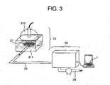
- Fig. 3 is a schematic view showing a structure of an exhaled air analyzing system.
- the exhaled air analyzing system 3 has a heating device 31 for containing the collecting filter 21 removed from the exhaled air collecting apparatus 1 (refer to fig. 1) and removing or vaporizing or reproducing the component of the exhaled air from the adsorbent 211 (refer to fig.
- the exhaled air analyzing system may has a terminal t to be electrically connected to the analyzing device 32 to analyze an analyzing result of the analyzing device 32.
- the heating part 312 includes, for example, a lamp light source, electric heater, an infra-red radiation heater or the like.
- the analyzing device 32 may have GC, ion-mobility, mass spectrometer, GC/MS (Gas Chromatography/Mass Spectrometer) or a combination thereof, but may have any device for analyzing the component.
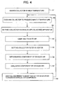
- Fig. 4 is a flow chart showing a process for mesuring the component of the exhaled air.
- the adsorbing part 2 is baked in high temperature (S1) to be pretreated for preventing unforeknown gas component from being adsorbed by the adsorbent 211.
- S1 high temperature
- it is cooled to a predetermined temperature in a clean gaseous environment of nitrogen, helium or the like (S2).
- the exhaled air receiving part 12 is attached onto the mouth of the test subject 11, and the exhaled air of the test subject 11 is sampled when the test subject 11 discharges the exhaled air into the exhaled air collecting apparatus 1 (S4).
- the component of the exhaled air of high volatility needs to be measured, the component can be analyzed in high sensitivity by cooling the exhaled air collecting part 13 during the sampling to make the component effectively be adsorbed by a surface of the adsorbent 211.
- the component of the exhaled air of low volatility needs to be measured, the component can be analyzed in high sensitivity by heating the exhaled air collecting part 13 to a temperature preventing the component from being removed from the exhaled air collecting part 13 during the sampling to make another component of high volatility not to be measured be restrained from being adsorbed by the adsorbent 211, so that an affection of noise component during analyzing is decreased.
- the exhaled air is collected while the amount of the exhaled air to be sampled is measured by a flow meter 15 mounted on the pipe 16a.
- the amount of the exhaled air to be sampled is preferably 1 1 / one sampling cycle.
- the amount of the exhaled air to be sampled is varied in accordance with the sensitivity of sensor and the component of the exhaled air to be measured.
- the adsorbing filter 21 is removed from the exhaled air collecting part 13, and mounted in the heating chamber 311 of the heating device 31 in the exhaled air analyzing system 3 (S5).
- the heating part 31 heats the heating chamber 311 to remove or vaporize or reproduce the component of the exhaled air from the adsorbing filter 21 so that the removed component of the exhaled air is collected (S6).
- the heat energy of, for example, the lamp light source is used.
- the collected component of the exhaled air is transferred to the analyzing device 32 through the pipe 33.
- the analyzing device 32 analyzes the transferred component of the exhaled air (S7).
- the analyzing device 32 can perform the analysis with the mass spectrograph, GC, GC/MS (Gas Chromatography/Mass Spectrometer) or the like.
- the adsorbent 211 after finishing the measurement is heated in inert gas environment to remove completely the adsorbed component of the exhaled air (S8). By this treatment, the adsorbent 211 becomes reusable. If the sampling is not performed just after the heating, it is preferable that the adsorbent is contained in a hermetically sealed container to prevent the atmosphere from being adsorbed.
- the adsorbent By arranging the adsorbent in such a manner that both (AL - V) 2 / L 3 ⁇ 0. 003 [mm 3 ] and V /Al ⁇ 0.3(30%) are satisfied, the adsorbing filter by which the pressure loss is low, the load of the test subject is small, and a collecting efficiency of the component is high, is obtainable.
- Table 1 shows a comparison between exhaled air collecting method as comparative examples and the exhaled air collecting method as the embodiment.
- the exhaled air collecting method are, for example, a method with using a container (bag) (for example, the method disclosed by the patent document 2) and a method with using adsorbent (for example, the method disclosed by the patent document 1), and the embodiment is the method with using the adsorbing filter.
- a container for example, the method disclosed by the patent document 2
- adsorbent for example, the method disclosed by the patent document 1
- the collecting efficiency of the component of the exhaled air is obtained from the experimental result using heptane as the reference standard.
- table 1 Exhaled air collecting method Container (bag) collecting Method with solid adsorption Method with adsorbing filter Pressure loss of adsorbing part ⁇ 1kPa 40 kPa ⁇ 1kPa Collecting efficiency of exhaled air component (experimental result with using heptane as reference specimen) 10% 90% 50-70%
- the pressure loss of the adsorbing part is not more than 1 [kPa] so that the load of the test subject is small, but the component collecting efficiency is about 10%, that is, low.
- the component collecting efficiency is about 90%, that is, high, but the pressure loss of the adsorbing part is 40 [kPa] so that the load of the test subject is great.
- the pressure loss of the adsorbing part is not more than 1 [kPa] so that the load of the test subject is small, and the component collecting efficiency is about 50-70%, that is, high, so that an improved sampling is obtainable.
- An adsorbent temperature controller as shown in fig. 1 may heat the exhaled air to a temperature more than a temperature of the exhaled air received at the exhaled air receiving part 12 and/or heat the adsorbent to a temperature more than an atmospheric or environmental temperature and/or more than the temperature of the exhaled air received at the exhaled air receiving part 12, and/or may cool the exhaled air to a temperature less than a temperature of the exhaled air received at the exhaled air receiving part 12 and/or cool the adsorbent to a temperature less than the atmospheric or environmental temperature and/or less than the temperature of the exhaled air received at the exhaled air receiving part 12.
Landscapes
- Health & Medical Sciences (AREA)
- Life Sciences & Earth Sciences (AREA)
- Engineering & Computer Science (AREA)
- Molecular Biology (AREA)
- Physics & Mathematics (AREA)
- Biomedical Technology (AREA)
- General Health & Medical Sciences (AREA)
- Pathology (AREA)
- Biophysics (AREA)
- Chemical & Material Sciences (AREA)
- Hematology (AREA)
- Heart & Thoracic Surgery (AREA)
- Surgery (AREA)
- Animal Behavior & Ethology (AREA)
- Physiology (AREA)
- Public Health (AREA)
- Veterinary Medicine (AREA)
- Medical Informatics (AREA)
- Urology & Nephrology (AREA)
- Pulmonology (AREA)
- Food Science & Technology (AREA)
- Medicinal Chemistry (AREA)
- Analytical Chemistry (AREA)
- Biochemistry (AREA)
- General Physics & Mathematics (AREA)
- Immunology (AREA)
- Sampling And Sample Adjustment (AREA)
- Investigating Or Analysing Biological Materials (AREA)
- Measurement Of The Respiration, Hearing Ability, Form, And Blood Characteristics Of Living Organisms (AREA)
Abstract
Description
- The present invention relates to an exhaled air filter, exhaled air collecting apparatus, exhaled air analyzing system and exhaled air analyzing method, for analyzing a component in an exhaled air of mammals.
-
JP-A-10-206293 -
JP-A-2003-171317 -
JP-A-8-51098 - An object of the present invention is to provide an exhaled air filter, exhaled air collecting apparatus, exhaled analyzing system and exhaled air analyzing method, for analyzing a component in an exhaled air of mammals, by which a physical burden of a test subject on collecting the component in the exhaled air can be decreased, and an efficiency of collecting or adsorbing the component in the exhaled air can be improved.
- According to the invention, a filter for collecting a component of an exhaled air, comprises, an adsorbent for adsorbing the component of the exhaled air, and a collector body including a passage hole in which the adsorbent is contained and through which the exhaled air is capable of passing.
- It is preferable for decreasing the physical burden of the test subject on collecting the component in the exhaled air that when a total amount of volume of the adsorbent is V, a total amount of cross sectional area of the passage hole is A, and a length of the passage hole is L, (AL - V) 2/L3 ≥ 0.003mm3, and V / AL ≥ 0.3.
- If the collector body has a pair of meshes covering respective opening ends (opposite to each other in a flow direction of the exhaled air) of the passage hole to prevent the adsorbent from moving out of the passage hole and to allow the exhaled air to pass through the meshes, a flow resistance for the exhaled gas can be kept constant with a correct thickness of the meshes.
- If the collector body includes a plurality of the passage holes arranged in parallel in a flow direction of the exhaled air (and juxtaposed to each other in a radial direction perpendicular to the flow direction) so that the passage holes are capable of passing respective parts of the exhaled air in parallel, the flow resistance for the exhaled gas can be decreased to decrease the physical burden of the test subject on collecting the component in the exhaled air. If the collector body has a partition wall between the passage holes to prevent the parts of the exhaled air in the respective passage holes from fluidly communicating with each other in a direction perpendicular to the flow direction of the exhaled air in the collector body and to restrain the adsorbent in each of the passage holes from being gathered or condensed to one radial side of the passage hole in by weight of the adsorbent in the direction perpendicular to the flow direction of the exhaled air in the collector body or a longitudinal direction of the passage hole so that a clearance between an inner peripheral surface of the passage hole and the adsorbent is restrained from forming in the passage hole and the exhaled gas is restrained from passing through the clearance in the longitudinal direction of the passage hole without passing through the adsorbent while the exhaled gas can sufficiently contact the adsorbent so that the component in the exhaled gas can be efficiently adsorbed on the adsorbent, the flow resistance for the exhaled air can be kept constant and low to decrease the physical burden of the test subject on collecting the component in the exhaled air, and the efficiency of collecting or adsorbing the component in the exhaled air can be improved by preventing the absorbent (granular) from being condensed by the weight of the absorbent itself. If the collector body has a pair of meshes covering respective opening ends of each of the passage holes to prevent the adsorbent from moving out of the passage hole and to allow the exhaled air to pass through the meshes, and each of the meshes extends monolithically to cover the opening ends of the passage holes (while being prevented from extending into the passage holes), a fluidal communication over the opening ends of the passage holes through each of the meshes is obtained so that the exhaled air can be distributed correctly evenly to the opening ends of the passage holes, the passage holes can be treated as a monolithic one piece unit, and a temperature of the adsorbents in the passage holes and a temperature of the exhaled airs taken into the passage holes respectively can be kept evenly over the passage holes, that is, a difference in inner (adsorbent) temperature between the passage holes is minimized and a difference in exhaled air taken into the passage hole between the passage holes is minimized.
- If the collector body (including the meshes and inner peripheral surfaces of the passage holes) is metallic, a temperature of the adsorbent in the passage hole can be kept evenly in each of longitudinal and radial directions of the passage hole, and/or a temperature of the adsorbents in the passage holes can be kept evenly over the passage holes, that is a difference in inner (adsorbent) temperature between the passage holes is minimized, (while little amount of impurities are emitted from the material of the collector body and back-ground noise level is reduced).
- It is preferable that the adsorbent includes a carbon type adsorbent.
- According to the invention, an apparatus for collecting an exhaled air, comprises, an inlet for receiving the exhaled air from a test subject, and the filter as recited in claims 1-11 for collecting a component of the exhaled air, wherein the filter includes an adsorbent for adsorbing the component of the exhaled air, and a collector body including a passage hole in which the adsorbent is contained and through which the exhaled air is capable of passing.
- The apparatus may further comprise a flow meter (preferably mass flow meter) for measuring a flow rate of the exhaled air passing through the passage hole to measure a total amount of the exhaled air passing through the passage hole to be compared with a total amount of the removed and measured component of the exhaled air so that a concentration of the component in the exhaled gas is calculated. The apparatus may further comprise a suction pump fluidly connected to one of opening ends of the passage hole to accelerate a flow of the exhaled air from the other one of the opening ends toward the one of the opening ends so that the physical burden of the test subject is decreased. The apparatus may further comprise a heater for heating the adsorbent to remove or vaporize or reproduce the component from the adsorbent, and an analyzer for analyzing the component removed or vaporizes or reproduced from the adsorbent. It is preferable that the heater is capable of generating a radiant heat for irradiating the filter. The analyzer may include at least one of a mass spectrometer and a gas chromatograph.
- According to the invention, a method for analyzing an exhaled air, in an apparatus for collecting an exhaled air, including an inlet for receiving the exhaled air from a test subject, and a filter for collecting a component of the exhaled air, wherein the filter includes an adsorbent for adsorbing the component of the exhaled air, and a collector body including a passage hole in which the adsorbent is contained and through which the exhaled air is capable of passing, comprising the steps of:
- receiving the exhaled air at the inlet so that the exhaled air is allowed to pass through the passage hole, heating the adsorbent to remove or vaporize or reproduce the component from the adsorbent, and analyzing the removed or vaporized or reproduced component.
- It is preferable for collecting and measuring the component of the exhaled air of low volatility and preventing the component of the exhaled air of high volatility from being adsorbed by the adsorbent that the method further comprises the step of heating the adsorbent to a temperature (more than an estimated temperature of the exhaled air to be received at the inlet) preventing the component to be measured from being removed or vaporized or reproduced from the adsorbent during the adsorption and making another component of high volatility not to be measured or detected be restrained from being adsorbed by the adsorbent before the step of receiving the exhaled air at the inlet, because the component can be analyzed in high sensitivity by heating the adsorbent to the temperature preventing the component to be measured from being removed or vaporized or reproduced from the adsorbent during the adsorption to make another component of high volatility not to be measured or detected be restrained from being adsorbed by the adsorbent.
- It is preferable for collecting and measuring the component of the exhaled air of low volatility and preventing the component of the exhaled air of high volatility from being adsorbed by the adsorbent that a temperature of the adsorbent is kept at a temperature more than a temperature of the exhaled air received at the inlet, in the step of receiving the exhaled air, the temperature preventing the component to be measured from being removed or vaporized or reproduced from the adsorbent during the adsorption and making another component of high volatility not to be measured or detected be restrained from being adsorbed by the adsorbent, because the component can be analyzed in high sensitivity by heating the adsorbent to heat the exhaled air to the temperature preventing the component of low volatility to be measured from being removed or vaporized or reproduced from the adsorbent during the adsorption to make another component of high volatility not to be measured or detected be restrained from being adsorbed by the adsorbent.
- It is preferable for collecting and measuring the component of the exhaled air of high volatility, that a temperature of the adsorbent is kept less than a temperature of the exhaled air received at the inlet, in the step of receiving the exhaled air, because the component of high volatility can be condensed or liquefied by cooling the adsorbent to cool the exhaled air in the adsorbent during the adsorption to make the component effectively be adsorbed by a surface of the adsorbent. The temperature of the adsorbent may be kept less than the temperature of the exhaled air received at the inlet in the step of receiving the exhaled air, after the step of heating the adsorbent, so that the exhaled air of high volatility is prevented or restrained from being adsorbed by the adsorbent before the step of receiving the exhaled air.
- Other objects, features and advantages of the invention will become apparent from the following description of the embodiments of the invention taken in conjunction with the accompanying drawings.
-
- Fig. 1 is a schematic view showing an exhaled air collecting apparatus as an embodiment of the invention.
- Fig. 2a is a schematic cross sectional view showing a filter of the invention.
- Fig. 2b is a schematic cross sectional view taken along IIb-IIb in fig. 2a.
- Fig. 3 is a schematic oblique projection view showing an exhaled air analyzing system.
- Fig. 4 is a flow chart of handling process for a component of the exhaled gas.
- An exhaled cir collecting filter, exhaled air collecting apparatus and exhaled air analyzing system as embodiments of the invention will be described with making reference to the drawings.
- Fig. 1 is a schematic view showing the exhaled air collecting apparatus as the embodiment.
- As shown in fig. 1, the exhaled air collecting apparatus 1 has an exhaled
air receiving part 12 for receiving an exhaled air of atest subject 11, and an exhaledair collecting part 13 connected to the exhaledair receiving part 12 and including an adsorbing part (an exhaled air collecting filter) 2 for collecting a component of the exhaled air. Further, the exhaled air collecting apparatus 1 has asuction pump 14 arranged at a downstream side of the exhaledair collecting part 13 and connected to the exhaledair collecting part 13 through apipe 16a so that a pressure at the downstream side of the exhaledair collecting part 13 and thepipe 16a is decreased, and aflow meter 15 arranged at a downstream side of thesuction pump 14 and connected to thesuction pump 14 through apipe 16b so that an amount of the collected exhaled air is measured. Hexe, the amount of the exhaled air is an amount of the exhaled air flowing in a unit time period. Incidentally, theflow meter 15 may be arranged on thepipe 16a at an upstream side of thesuction pump 14. Further, the exhaled air collecting apparatus 1 may have avalve 17 arranged on thepipe 16a to adjust the amount of the exhaled gas flowing in thepipe 16a. - Incidentally, the exhaled
air receiving part 12 has preferably a mask shape covering a mouth, but may have a pipe shape to be fressed in the mouth to receive the exhaled air. - The
test subject 11 holds the exhaledair receiving part 12 at the mouth and discharges the exhaled air. The discharged exhaled air is fed to the exhaledair collecting part 13. The component of the exhaled air fed to the exhaledair collecting part 13 is adsorbed in an adsorbent 211 (refer to fig. 2) in theadsorbing part 2 arranged in the exhaledair collecting part 13. Another component not adsorbed by theadsorbent 211 is discharged out of the system through thepipe 16a,valve 17,suction pump 14 andpipe 16b. It is preferable that thesuction pump 14 is arranged at the downstream side of the exhaledair collecting part 13 to decrease the pressure at the downstream side of the exhaledair collecting part 13 and thepipe 16a to decrease a load for thetest subject 11. Further, thevalve 17 may be arranged on thepipe 16a to adjust the amount of the exhaled air flowing in thepipe 16a. Further, it is preferable that theflow meter 15 is arranged at the upstream or downstream side of the suction pump 14 (only thesuction pump 14 arranged at the downstream side is shown in the drawings as the embodiment) to detect the amount of the exhaled air discharged to the exhaled air collecting apparatus 1. Since an amount of the component of the exhaled air collected by the adsorbent 211 depends on the amount of the exhaled air, it is important for keeping sampling condition constant that the amount of the exhaled air is measured by theflow meter 15. - Fig. 2 is a view showing a structure of the adsorbing part of the embodiment, fig. 2a is a cross sectional side view of the adsorbent part, and fig. 2b is a cross sectional view taken along A-A in fig. 2a.
- Hereafter, the structure of the
adsorbing part 2 will be explained with making reference to fig. 2. - As shown in fig. 2a, the
adsorbing part 2 hasmeshes 22 contacting respective surfaces of the adsorbingfilter 21. Themeshes 22 may be or may not be adhered to the adsorbingfilter 21. Theadsorbing filter 21 has theadsorbent 211 for adsorbing the component of the exhaled air, and a metallic sheet (collecting part) 212 for holding theadsorbent 211. Themetallic sheet 212 hasholes 213 extending from a predetermined (upstream) surface to another (downstream) surface. As shown in fig. 2b, thegranular adsorbent 211 is contained in theholes 213. A clearance size of themeshes 22 is smaller than a granular diameter of the adsorbent 211, so that the adsorbent 211 is prevented from flowing out of theholes 213. Further, if a periphery of the adsorbingpart 2 or collectingfilter 21 is hermetically sealed (not shown) to prevent the exhaled air from being discharged from the periphery of the adsorbingpart 2, a rate of the exhaled air passing through theholes 213 containing the adsorbent 211 is increased to improve an adsorbing efficiency of the exhaled air. A material of themetallic sheet 212 and meshes 22 is preferably for preventing a gas from being emitted when being heated, for example, stainless steel or the like. The adsorbent 211 may be selected in accordance with the component to be detected, for example, may be carbon type adsorbent. Concretely, for example, TENAX TA® or TENAX GR® of Buchem BV is generally used. - Next, the structure and action of the collecting
filter 21 will be explained in detail with making reference to figs. 1 and 2.. - The exhaled
air receiving part 12 as the mask is attached to the test subject 11 so that the exhaled air of thetest subject 11 is discharged to the adsorbingpart 2 in the exhaledair collecting part 13. The component of the exhaled air such as hydrocarbon-type matter is selectively adsorbed by the adsorbent 211, and an inert gas such as nitrogen is not adsorbed and is discharged to the downstream side of the adsorbingpart 2. When the downstream side of the adsorbingpart 2 is of atmospheric temperature, the pressure of the upstream side of the adsorbingpart 2 is higher than that of the downstream side thereof due to a pressure loss caused by passage of the exhaled air through the adsorbingpart 2, to form a resistance against the discharge of the exhaled from thetest subject 11. Therefore, the lower the pressure loss is, the lower the pressure at the upstream side of the adsorbingpart 2 is, so that the test subject 11 can discharge without effort the exhaled air. A relationship between the amount of the exhaled air flowing through the adsorbingpart 2 and the pressure loss caused thereby is as mentioned below. - When a total amount of cross sectional areas of the holes 213 (hereafter, called as cross sectional area) is A, a length of the
holes 213 is L, and a total amount of volumes of the adsorbent 211 in theholes 213 is V, a volume through which the exhaled air is capable of passing in the collectingfilter 21 is AL - V. Therefore, an apparent cross sectional area through which the exhaled air is capable of passing is,
- Further, the pressure loss P between the upstream and downstream sides of the adsorbing
part 2 is
where, Q: the amount of the exhaled air, C: conductance. - The conductance C of cylindrical tube (under the atmosphere of 20°C) is estimated from

where, d: apparent inner diameter of the cylindrical tube = 2 · ( (AL - V) / πL)1/2, P1 : pressure at upstream side of adsorbingpart 2, P2 : pressure at downstream side of adsorbingpart 2. - In this way, from the total amount volume of the used
adsorbent 211, the amount of exhaled air Q and so forth, the pressure loss P can be calculated. Here, when the maximum value of the amount of the exhaled gas during normal breathing is about 4 [1 / min], and the pressure loss between the upstream and downstream sides of the adsorbingpart 2 on this time should be not more than 10 [kPa], that is,
from an experimental result by the inventors, the load during sampling the exhaled air cannot be felt or is sufficiently or extremely low. - That is, when P1 = 110×103 [Pa], P2 = 100×103 [Pa], Q = 4 × 10-3×105 /60 [Pa · m3 / s] are incorporated into the
formulas 3 and 4, and theformula 3 is incorporated into the formula 4,
so that (AL - V)2 / L3 ≥ 0.003 [mm3] is satisfied to generate the pressure loss not more than 10 [kPa] for preventing the test subject 11 from feeling the load when the test subject 11 discharge the amount of the exhaled air of 4 [1 / min]. - On the other hand, for analyzing the component of the exhaled air, it is preferable for the exhaled gas to contact as largely as possible to accelerate the adsorption of the component of the exhaled air. That is, if the above mentioned ratio of between AL and V (a rate in volume of the adsorbent 211 with respect to the holes 213) V / AL is excessively small (few), a major part of the component of the exhaled air does not contact the adsorbent 211 and is discharged to the exterior, so that a sensitive measurement is not obtainable, From the experimental result by the inventors, when V / AL is not less than 80%, an adsorbing efficiency is not less than 90%, but, the adsorbing efficiency decreases to about 50% when V / AL is 30%, and the adsorbing efficiency decreases to about 10% when V / AL is 10%, so that it is preferable that V / AL ≥ 30%.
- The smaller the particle diameter of the adsorbent 211 is, the greater a surface area thereof per the same volume is, to increase a performance of adsorbing the component of the exhaled air, but the higher the rate in volume of the adsorbent 211 with respect to the
holes 213 to increase the pressure loss. Therefore, theholes 213 may have complicated surface shape to increase a surface area of theholes 213, so that if the particle diameter is not changed, the adsorbing efficiency is increased without significant increase of the pressure loss. - If the used amount of the adsorbent 211 is not.changed, it is effective for decreasing the pressure loss between the upstream and downstream sides of the adsorbing
part 2 and decreasing a flowing velocity of the air through the collectingfilter 21 that a cross sectional area A is increased. But, if themetallic sheet 212 as shown in fig. 2 is not used and the adsorbent 211 is held only between the meshes 22 (that is, a diameter of thehole 213 is increased significantly), the adsorbent 211 moves to one side in each of the holes when the collecting part'2 is moved so that the major part of the exhaled air to be sampled discharged out of the system without contacting the adsorbent 211. As described above, themetallic sheet 212 has theholes 213 is effective for preventing the adsorbent 211 from moving. - As an example of the collecting
part 2 as shown in fig. 2, when an inner diameter of each of theholes 213 is 3×10⁻³ [m], a length of theholes 213 is 0.8×10⁻³ [m], a number of the holes is 31, mesh size is about 250µm, the absorbent 211 is TENAX TA® of Buchem BV® (diameter of about 250µm), and a total mount of volume of the adsorbent is about 106×10-6 [m3], since a total amount of cross sectional areas of theholes 213 without the adsorbent 211 therein is about 219×10-6 [m2], a total amount of volumes of theholes 213 is about 219×10-6×0.8×10-3 = 175×10-9[m3]. Therefore, the rate in volume of the adsorbent with respect to the holes 213 (V / AL) is about 60%. Further, (AL / V)2 /L3 = (175×10-9 106x10-9)2 / (0.8×10⁻³)3≒9300×10-9[m3] = 9300 [mm3], so that both (AL - V)2 / L3 ≥ 0.003 [mm3] and V /Al ≥ 0.3(30%) are satisfied.
When actually the collectingfilter 21 of the embodiment was used and the exhaled air flowed at 4 [1 / min], the pressure loss was about 1 [kPa] as experimentally confirmed, and sufficiently lower than 10[kPa] at which the test subject feels generally the resistance. - A collecting efficiency obtained when this collecting
part 2 was used and heptane was used as reference standard, was 50-70% sufficient for analyzing. - Fig. 3 is a schematic view showing a structure of an exhaled air analyzing system.
- As shown in fig. 3, the exhaled
air analyzing system 3 has aheating device 31 for containing the collectingfilter 21 removed from the exhaled air collecting apparatus 1 (refer to fig. 1) and removing or vaporizing or reproducing the component of the exhaled air from the adsorbent 211 (refer to fig. 2) by heating, an analyzing device for analyzing the component of the exhaled air removed or vaporized or reproduced from the adsorbingfilter 21 by being heated by theheating device 31, apipe 33 connecting theheating device 31 and analyzing device to each other to transfer the component of the exhaled air removed or vaporized or reproduced by theheating device 31 to the analyzingdevice 32, and adischarge pipe 34 for discharging the component of the exhaled air analyzed by the analyzingdevice 32 to the outside of the system. The heating device has a heating chamber for containing the removed adsorbingfilter 21, and aheating part 312 for heating theheating chamber 311. Further, the exhaled air analyzing system may has a terminal t to be electrically connected to the analyzingdevice 32 to analyze an analyzing result of the analyzingdevice 32. Theheating part 312 includes, for example, a lamp light source, electric heater, an infra-red radiation heater or the like. The analyzingdevice 32 may have GC, ion-mobility, mass spectrometer, GC/MS (Gas Chromatography/Mass Spectrometer) or a combination thereof, but may have any device for analyzing the component. - Fig. 4 is a flow chart showing a process for mesuring the component of the exhaled air.
- The measuring process of the component of the exhaled air is explained along fig. 4 with making reference to figs. 1-3.
- At first, the adsorbing
part 2 is baked in high temperature (S1) to be pretreated for preventing unforeknown gas component from being adsorbed by the adsorbent 211. Next, it is cooled to a predetermined temperature in a clean gaseous environment of nitrogen, helium or the like (S2). The exhaledair receiving part 12 is attached onto the mouth of thetest subject 11, and the exhaled air of thetest subject 11 is sampled when the test subject 11 discharges the exhaled air into the exhaled air collecting apparatus 1 (S4). In this time, if the component of the exhaled air of high volatility needs to be measured, the component can be analyzed in high sensitivity by cooling the exhaledair collecting part 13 during the sampling to make the component effectively be adsorbed by a surface of the adsorbent 211. On the contrary, if the component of the exhaled air of low volatility needs to be measured, the component can be analyzed in high sensitivity by heating the exhaledair collecting part 13 to a temperature preventing the component from being removed from the exhaledair collecting part 13 during the sampling to make another component of high volatility not to be measured be restrained from being adsorbed by the adsorbent 211, so that an affection of noise component during analyzing is decreased. Incidentally, in this time, the exhaled air is collected while the amount of the exhaled air to be sampled is measured by aflow meter 15 mounted on thepipe 16a. The amount of the exhaled air to be sampled is preferably 1 1 / one sampling cycle. The amount of the exhaled air to be sampled is varied in accordance with the sensitivity of sensor and the component of the exhaled air to be measured. - After collecting the exhaled air, the adsorbing
filter 21 is removed from the exhaledair collecting part 13, and mounted in theheating chamber 311 of theheating device 31 in the exhaled air analyzing system 3 (S5). Theheating part 31 heats theheating chamber 311 to remove or vaporize or reproduce the component of the exhaled air from the adsorbingfilter 21 so that the removed component of the exhaled air is collected (S6). For heating, the heat energy of, for example, the lamp light source is used. The collected component of the exhaled air is transferred to the analyzingdevice 32 through thepipe 33. The analyzingdevice 32 analyzes the transferred component of the exhaled air (S7). The analyzingdevice 32 can perform the analysis with the mass spectrograph, GC, GC/MS (Gas Chromatography/Mass Spectrometer) or the like. - The adsorbent 211 after finishing the measurement is heated in inert gas environment to remove completely the adsorbed component of the exhaled air (S8). By this treatment, the adsorbent 211 becomes reusable. If the sampling is not performed just after the heating, it is preferable that the adsorbent is contained in a hermetically sealed container to prevent the atmosphere from being adsorbed.
- By arranging the adsorbent in such a manner that both (AL - V)2 / L3 ≥ 0. 003 [mm3] and V /Al ≥ 0.3(30%) are satisfied, the adsorbing filter by which the pressure loss is low, the load of the test subject is small, and a collecting efficiency of the component is high, is obtainable.
- Table 1 shows a comparison between exhaled air collecting method as comparative examples and the exhaled air collecting method as the embodiment.
- Here, the exhaled air collecting method are, for example, a method with using a container (bag) (for example, the method disclosed by the patent document 2) and a method with using adsorbent (for example, the method disclosed by the patent document 1), and the embodiment is the method with using the adsorbing filter.
- On table 1, a relationship in the pressure loss of the adsorbing part 57 and the collecting efficiency of the component of the exhaled air among the exhaled air collecting methods of the method by collecting with the bag, the method by solid adsorption and the method by the adsorbing filter is shown.
- Incidentally, the collecting efficiency of the component of the exhaled air is obtained from the experimental result using heptane as the reference standard.
table 1 Exhaled air collecting method Container (bag) collecting Method with solid adsorption Method with adsorbing filter Pressure loss of adsorbing part ≤ 1kPa 40 kPa ≤ 1kPa Collecting efficiency of exhaled air component (experimental result with using heptane as reference specimen) 10% 90% 50-70% - As shown in table 1, in the method by container collecting, the pressure loss of the adsorbing part is not more than 1 [kPa] so that the load of the test subject is small, but the component collecting efficiency is about 10%, that is, low.
- On the other hand, in the method by solid adsorption, the component collecting efficiency is about 90%, that is, high, but the pressure loss of the adsorbing part is 40 [kPa] so that the load of the test subject is great.
- In the method with the adsorbing filter of the embodiment, the pressure loss of the adsorbing part is not more than 1 [kPa] so that the load of the test subject is small, and the component collecting efficiency is about 50-70%, that is, high, so that an improved sampling is obtainable.
- An adsorbent temperature controller as shown in fig. 1 may heat the exhaled air to a temperature more than a temperature of the exhaled air received at the exhaled
air receiving part 12 and/or heat the adsorbent to a temperature more than an atmospheric or environmental temperature and/or more than the temperature of the exhaled air received at the exhaledair receiving part 12, and/or may cool the exhaled air to a temperature less than a temperature of the exhaled air received at the exhaledair receiving part 12 and/or cool the adsorbent to a temperature less than the atmospheric or environmental temperature and/or less than the temperature of the exhaled air received at the exhaledair receiving part 12. - It should be further understood by those skilled in the art that although the foregoing description has been made on embodiments of the invention, the invention is not limited thereto and various changes and modifications may be made without departing from the spirit of the invention and the scope of the appended claims.
Claims (20)
- A filter for collecting a component of an exhaled air, comprising,
an adsorbent (211) for adsorbing the component of the exhaled air, and
a collector body (2) including a passage hole (213) in which the adsorbent is contained and through which the exhaled air is capable of passing. - A filter according to claim 1, wherein when a total amount of volume of the adsorbent is V, a total amount of cross sectional area of the passage hole is A, and a length of the passage hole is L, (AL - V)2/L3 ≥ 0.003mm3, and V / AL ≥ 0.3.
- A filter according to claim 1 or 2, wherein the collector body has a pair of meshes (22) covering respective opening ends of the passage hole to prevent the adsorbent from moving out of the passage hole and to allow the exhaled air to pass through the meshes.
- A filter according to any one of claims 1-3,
wherein the collector body includes a plurality of the passage holes arranged in parallel in a flow direction of the exhaled air so that the passage holes are capable of passing respective parts of the exhaled air in parallel. - A filter according to claim 4, wherein the collector body has a partition wall between the passage holes to prevent the parts of the exhaled air in the respective passage holes from fluidly communicating with each other in a direction perpendicular to the flow direction of the exhaled air in the collector body.
- A filter according to claim 4 or 5, wherein the collector body has a pair of meshes (22) covering respective opening ends of each of the passage holes to prevent the adsorbent from moving out of the passage hole and to allow the exhaled air to pass through the meshes, and each of the meshes extends monolithically to cover the opening ends of the passage holes.
- A filter according to any one of claims 1-6,
wherein the collector body is metallic. - A filter according to any one of claims 1-7,
wherein the adsorbent includes a carbon type adsorbent. - An apparatus for collecting an exhaled air of a test subject, comprising,
an inlet (12) for receiving the exhaled air from the test subject, and a filter for collecting a component of the exhaled air,
wherein the filter includes an adsorbent (211) for adsorbing the component of the exhaled air, and a collector body (2) including a passage hole in which the adsorbent is contained and through which the exhaled air is capable of passing. - An apparatus according to claim 9, wherein when a total amount of volume of the adsorbent is V, a total amount of cross sectional area of the passage hole is A, and a length of the passage hole is L, (AL - V)2/L3 ≥ 0.003mm3, and V / AL ≥ 0.3.
- An apparatus according to claim 9 or 10,
wherein the collector body has a pair of meshes covering respective opening ends of the passage hole to prevent the adsorbent from moving out of the passage hole and to allow the exhaled air to pass through the meshes. - An apparatus according to any one of claims 9-11, further comprising a flow meter for measuring a flow rate of the exhaled air passing through the passage hole to measure a total amount of the exhaled air passing through the passage hole.
- An apparatus according to any one of claims 9-12, further comprising a suction pump fluidly connected to one of opening ends of the passage hole to accelerate a flow of the exhaled air from the other one of the opening ends toward the one of the opening ends.
- An apparatus according to any one of claims 9-13, further comprising a heater for heating the adsorbent to remove the component from the adsorbent, and an analyzer for analyzing the component removed from the adsorbent.
- An apparatus according to claim 14, wherein the heater is capable of generating a radiant heat for irradiating the filter.
- An apparatus according to claim 14 or 15,
wherein the analyzer includes at least one of a mass spectrometer and a gas chromatograph. - A method for analyzing an exhaled air, in an apparatus for collecting an exhaled air, including an inlet for receiving the exhaled air from a test subject, and a filter for collecting a component of the exhaled air, wherein the filter includes an adsorbent for adsorbing the component of the exhaled air, and a collector body including a passage hole in which the adsorbent is contained and through which the exhaled air is capable of passing, comprising the steps of:receiving the exhaled air at the inlet so that the exhaled air is allowed to pass through the passage hole,heating the adsorbent to remove the component from the adsorbent, andanalyzing the removed component.
- A method according to claim 17, further comprising the step of
heating the adsorbent before the step of receiving the exhaled air at the inlet. - A method according to claim 17 or 18, wherein a temperature of the adsorbent is kept at a temperature more than a temperature of the exhaled air received at the inlet, in the step of receiving the exhaled air.
- A method according to any one of claims 17-19, wherein a temperature of the adsorbent is kept at a temperature less than a temperature of the exhaled air received at the inlet, in the step of receiving the exhaled air.
Applications Claiming Priority (1)
| Application Number | Priority Date | Filing Date | Title |
|---|---|---|---|
| JP2005152810A JP4564406B2 (en) | 2005-05-25 | 2005-05-25 | Exhalation collection filter, exhalation collection device, exhalation analysis system, and exhalation analysis method |
Publications (2)
| Publication Number | Publication Date |
|---|---|
| EP1726258A2 true EP1726258A2 (en) | 2006-11-29 |
| EP1726258A3 EP1726258A3 (en) | 2007-03-28 |
Family
ID=37023118
Family Applications (1)
| Application Number | Title | Priority Date | Filing Date |
|---|---|---|---|
| EP05018413A Pending EP1726258A3 (en) | 2005-05-25 | 2005-08-24 | Exhaled-air filter, collecting apparatus, analyzing system and method |
Country Status (3)
| Country | Link |
|---|---|
| US (1) | US20060266353A1 (en) |
| EP (1) | EP1726258A3 (en) |
| JP (1) | JP4564406B2 (en) |
Cited By (5)
| Publication number | Priority date | Publication date | Assignee | Title |
|---|---|---|---|---|
| CN102589958A (en) * | 2011-12-08 | 2012-07-18 | 河北先河环保科技股份有限公司 | Device for purifying ozone gas |
| CN106796217A (en) * | 2014-07-21 | 2017-05-31 | 泰克年研究发展基金会公司 | For the composition of directly breathing sampling |
| EP3816605A1 (en) * | 2019-10-31 | 2021-05-05 | Arcadis U.S., Inc. | Passive sampler |
| CN115015203A (en) * | 2022-06-20 | 2022-09-06 | 之江实验室 | Exhaled aerosol microorganism rapid detection device |
| SE2150438A1 (en) * | 2021-04-08 | 2022-10-09 | Pinsalus Ab | System and Method for Breath Sampling and Breath Analysis |
Families Citing this family (16)
| Publication number | Priority date | Publication date | Assignee | Title |
|---|---|---|---|---|
| US7779840B2 (en) * | 2006-06-21 | 2010-08-24 | General Electric Company | Ventilator breath condensate sampler and method of collecting a breath condensate sample |
| JP4856514B2 (en) * | 2006-10-20 | 2012-01-18 | 株式会社日立製作所 | Exhalation component collector, exhalation component collection device, exhalation component collector manufacturing method, exhalation component analysis device, and exhalation component analysis method |
| EA023922B1 (en) | 2009-09-09 | 2016-07-29 | Сенса Буэс Аб | DETECTION OF MEDICINE IN EXHAUST AIR |
| EP2518499B1 (en) | 2011-03-09 | 2015-06-10 | Sensa Bues AB | A portable sampling device and method for drug detection from exhaled breath |
| EP3667317A1 (en) | 2012-03-08 | 2020-06-17 | Sensa Bues AB | A portable sampling device and method for detection of biomarkers in exhaled breath |
| EP2706355A1 (en) | 2012-09-11 | 2014-03-12 | Sensa Bues AB | System and method for eluting and testing substance from exhaled aerosol sample |
| JP6110116B2 (en) * | 2012-11-28 | 2017-04-05 | 日本写真印刷株式会社 | Gas component adsorption tube, gas component collection device, and gas component collection method. |
| JP2014232051A (en) * | 2013-05-29 | 2014-12-11 | 株式会社Nttドコモ | Apparatus and method for measuring skin gas |
| ES2734380T3 (en) | 2014-06-27 | 2019-12-05 | Pulse Health Llc | Analysis cartridge and method of use thereof |
| JP6967198B2 (en) * | 2017-05-18 | 2021-11-17 | 東海光学株式会社 | Breath mist collection device, breath mist analysis system, breath mist collection method and breath mist analysis method |
| US11209417B2 (en) | 2017-10-12 | 2021-12-28 | Carrot, Inc. | Breath sensor apparatus and methods of use |
| CN117883121A (en) | 2019-08-26 | 2024-04-16 | 泽特奥科技公司 | Diagnosis of tuberculosis and other diseases using exhaled breath |
| CA3166435A1 (en) | 2019-12-31 | 2021-07-08 | Mcneil Ab | Breath sensor calibration methods and apparatus |
| CN112932459B (en) * | 2021-01-29 | 2025-01-28 | 西安交通大学第二附属医院 | A non-invasive analysis device and system for respiratory disease detection |
| EP4312749A4 (en) | 2021-03-31 | 2025-07-09 | Zeteo Tech Inc | DIAGNOSIS OF RESPIRATORY DISEASES BY DETECTING AEROSOLIZED BIOMATERIAL PARTICLES USING PACKED-BED SYSTEMS AND METHODS |
| CN113188853B (en) * | 2021-04-29 | 2022-07-12 | 中国科学院生态环境研究中心 | Mask-type breath sampler and breath test mask |
Citations (3)
| Publication number | Priority date | Publication date | Assignee | Title |
|---|---|---|---|---|
| JPH0851098A (en) | 1994-08-08 | 1996-02-20 | Mitsubishi Electric Corp | Semiconductor processing equipment |
| JPH10206293A (en) | 1997-01-21 | 1998-08-07 | Suzuki Motor Corp | Exhaled air component collecting tube and its heating device |
| JP2003171317A (en) | 2001-12-05 | 2003-06-20 | Masahiro Kajiwara | Expiration test reagent, expiration test reagent kit, expiration test bag, expiration test device, and expiration test method |
Family Cites Families (9)
| Publication number | Priority date | Publication date | Assignee | Title |
|---|---|---|---|---|
| US3522009A (en) * | 1966-12-05 | 1970-07-28 | Indiana University Foundation | Breath sampling,storing,and processing apparatus and method |
| US4046014A (en) * | 1975-06-20 | 1977-09-06 | Boehringer John R | Sealable activated charcoal gas sampler |
| GB2078128B (en) * | 1980-06-24 | 1984-09-12 | Nat Res Dev | Monitoring gases |
| CA2098215A1 (en) * | 1992-06-12 | 1993-12-13 | Hideo Ueda | Expired gas analytical method and device |
| US5964221A (en) * | 1994-11-15 | 1999-10-12 | Gore Enterprise Holdings, Inc. | Rebreather adsorbent system |
| JP4270722B2 (en) * | 2000-06-28 | 2009-06-03 | 新コスモス電機株式会社 | Nozzle for gas detector |
| WO2003035219A2 (en) * | 2001-06-08 | 2003-05-01 | Donaldson Company, Inc. | Adsorption element and methods |
| JP2003185541A (en) * | 2001-12-17 | 2003-07-03 | Japan Science & Technology Corp | Passive sampler for capturing volatile organic compound |
| JP2004005878A (en) * | 2002-03-25 | 2004-01-08 | Kyocera Corp | Respiratory filter |
-
2005
- 2005-05-25 JP JP2005152810A patent/JP4564406B2/en not_active Expired - Fee Related
- 2005-08-24 EP EP05018413A patent/EP1726258A3/en active Pending
- 2005-08-25 US US11/210,738 patent/US20060266353A1/en not_active Abandoned
Patent Citations (3)
| Publication number | Priority date | Publication date | Assignee | Title |
|---|---|---|---|---|
| JPH0851098A (en) | 1994-08-08 | 1996-02-20 | Mitsubishi Electric Corp | Semiconductor processing equipment |
| JPH10206293A (en) | 1997-01-21 | 1998-08-07 | Suzuki Motor Corp | Exhaled air component collecting tube and its heating device |
| JP2003171317A (en) | 2001-12-05 | 2003-06-20 | Masahiro Kajiwara | Expiration test reagent, expiration test reagent kit, expiration test bag, expiration test device, and expiration test method |
Cited By (7)
| Publication number | Priority date | Publication date | Assignee | Title |
|---|---|---|---|---|
| CN102589958A (en) * | 2011-12-08 | 2012-07-18 | 河北先河环保科技股份有限公司 | Device for purifying ozone gas |
| CN106796217A (en) * | 2014-07-21 | 2017-05-31 | 泰克年研究发展基金会公司 | For the composition of directly breathing sampling |
| EP3816605A1 (en) * | 2019-10-31 | 2021-05-05 | Arcadis U.S., Inc. | Passive sampler |
| SE2150438A1 (en) * | 2021-04-08 | 2022-10-09 | Pinsalus Ab | System and Method for Breath Sampling and Breath Analysis |
| WO2022216217A1 (en) * | 2021-04-08 | 2022-10-13 | Pinsalus Ab | System and method for breath sampling and breath analysis |
| SE546321C2 (en) * | 2021-04-08 | 2024-10-01 | Pinsalus Ab | System for breath analysis comprising a breath sampling apparatus and a sample preparation apparatus |
| CN115015203A (en) * | 2022-06-20 | 2022-09-06 | 之江实验室 | Exhaled aerosol microorganism rapid detection device |
Also Published As
| Publication number | Publication date |
|---|---|
| JP4564406B2 (en) | 2010-10-20 |
| US20060266353A1 (en) | 2006-11-30 |
| EP1726258A3 (en) | 2007-03-28 |
| JP2006329779A (en) | 2006-12-07 |
Similar Documents
| Publication | Publication Date | Title |
|---|---|---|
| EP1726258A2 (en) | Exhaled-air filter, collecting apparatus, analyzing system and method | |
| US7882754B2 (en) | Gas component collector, gas component collecting device, filter producing method, and gas component analyzing apparatus | |
| US5284054A (en) | Method and apparatus for preparing a gas mixture for purposes of analysis and application of the method | |
| EP1721155B1 (en) | Systems for characterizing a sorbent tube | |
| US7430893B2 (en) | Systems and methods for detecting contaminants | |
| JP2021501880A (en) | High-speed quasi-ambient temperature multicapillary column preconcentration system for volatile chemical analysis by gas chromatography | |
| US20050120775A1 (en) | Systems and methods for detecting contaminants | |
| WO2005021134A1 (en) | Reactive gas filter | |
| JPH04274728A (en) | Preconcentration method and device for trace component analysis in gas | |
| WO2004086466A2 (en) | System and method for monitoring contamination | |
| US20040151622A1 (en) | Ultra-trace automatic mercury species analyzer | |
| JP3512321B2 (en) | Breath analyzer and breath analysis method | |
| US20060258017A1 (en) | Apparatus and methods for use in concentration of gas and particle-laden gas flows | |
| JPS58501787A (en) | Method and apparatus for continuous automatic air analysis | |
| JP2022080642A (en) | Gas collection device and gas collection method | |
| JP2001124748A (en) | High-speed analysis method and apparatus for chlorobenzene | |
| JP2002139431A (en) | Analyzer for trace organic matter in gas | |
| JP2001159592A (en) | Heat generation gas evaluation device | |
| JPH09281040A (en) | Carbon isotope analyzer | |
| JP2008151590A (en) | Gas analyzer | |
| JP2003307511A (en) | Method for analyzing organic substance in atmosphere in clean room | |
| JP4089646B2 (en) | Organic volatile matter collection tube and organic volatile matter measurement method | |
| JPH0247549A (en) | Analyzing apparatus of trace gas component | |
| JP4389078B2 (en) | Method for measuring organic volatiles in organic materials | |
| KR20210112114A (en) | Qualitative and quantitative analysis apparatus and method for inert gas |
Legal Events
| Date | Code | Title | Description |
|---|---|---|---|
| PUAI | Public reference made under article 153(3) epc to a published international application that has entered the european phase |
Free format text: ORIGINAL CODE: 0009012 |
|
| 17P | Request for examination filed |
Effective date: 20060331 |
|
| AK | Designated contracting states |
Kind code of ref document: A2 Designated state(s): AT BE BG CH CY CZ DE DK EE ES FI FR GB GR HU IE IS IT LI LT LU LV MC NL PL PT RO SE SI SK TR |
|
| AX | Request for extension of the european patent |
Extension state: AL BA HR MK YU |
|
| PUAL | Search report despatched |
Free format text: ORIGINAL CODE: 0009013 |
|
| AK | Designated contracting states |
Kind code of ref document: A3 Designated state(s): AT BE BG CH CY CZ DE DK EE ES FI FR GB GR HU IE IS IT LI LT LU LV MC NL PL PT RO SE SI SK TR |
|
| AX | Request for extension of the european patent |
Extension state: AL BA HR MK YU |
|
| AKX | Designation fees paid |
Designated state(s): DE FR GB |
|
| 18W | Application withdrawn |
Effective date: 20120911 |
|
| D18W | Application withdrawn (deleted) | ||
| STAA | Information on the status of an ep patent application or granted ep patent |
Free format text: STATUS: THE APPLICATION HAS BEEN WITHDRAWN |
|
| R18W | Application withdrawn (corrected) |
Effective date: 20120911 |