EP1726164B1 - Transflektive farb-recovery - Google Patents
Transflektive farb-recovery Download PDFInfo
- Publication number
- EP1726164B1 EP1726164B1 EP05724640A EP05724640A EP1726164B1 EP 1726164 B1 EP1726164 B1 EP 1726164B1 EP 05724640 A EP05724640 A EP 05724640A EP 05724640 A EP05724640 A EP 05724640A EP 1726164 B1 EP1726164 B1 EP 1726164B1
- Authority
- EP
- European Patent Office
- Prior art keywords
- light
- color filter
- recycling
- axis
- transflective color
- Prior art date
- Legal status (The legal status is an assumption and is not a legal conclusion. Google has not performed a legal analysis and makes no representation as to the accuracy of the status listed.)
- Expired - Lifetime
Links
- 238000011084 recovery Methods 0.000 title description 5
- 238000004064 recycling Methods 0.000 claims abstract description 67
- 238000000034 method Methods 0.000 claims abstract description 9
- 230000003287 optical effect Effects 0.000 claims description 71
- 230000010287 polarization Effects 0.000 claims description 24
- 238000003384 imaging method Methods 0.000 claims description 14
- 239000004973 liquid crystal related substance Substances 0.000 claims description 6
- 239000011248 coating agent Substances 0.000 claims description 5
- 238000000576 coating method Methods 0.000 claims description 5
- 238000005286 illumination Methods 0.000 abstract description 27
- 210000001747 pupil Anatomy 0.000 description 7
- 230000005540 biological transmission Effects 0.000 description 3
- 239000003086 colorant Substances 0.000 description 3
- 238000013461 design Methods 0.000 description 3
- 239000011521 glass Substances 0.000 description 3
- 239000004372 Polyvinyl alcohol Substances 0.000 description 2
- 238000013459 approach Methods 0.000 description 2
- 230000008901 benefit Effects 0.000 description 2
- 238000010276 construction Methods 0.000 description 2
- 230000001419 dependent effect Effects 0.000 description 2
- 238000010586 diagram Methods 0.000 description 2
- 230000000694 effects Effects 0.000 description 2
- 238000005516 engineering process Methods 0.000 description 2
- 238000012986 modification Methods 0.000 description 2
- 230000004048 modification Effects 0.000 description 2
- 229920002451 polyvinyl alcohol Polymers 0.000 description 2
- 229940068984 polyvinyl alcohol Drugs 0.000 description 2
- 235000019422 polyvinyl alcohol Nutrition 0.000 description 2
- 239000007787 solid Substances 0.000 description 2
- ZCYVEMRRCGMTRW-UHFFFAOYSA-N 7553-56-2 Chemical compound [I] ZCYVEMRRCGMTRW-UHFFFAOYSA-N 0.000 description 1
- 230000006978 adaptation Effects 0.000 description 1
- 238000006243 chemical reaction Methods 0.000 description 1
- 230000003098 cholesteric effect Effects 0.000 description 1
- 239000012141 concentrate Substances 0.000 description 1
- 230000008878 coupling Effects 0.000 description 1
- 238000010168 coupling process Methods 0.000 description 1
- 238000005859 coupling reaction Methods 0.000 description 1
- 238000011161 development Methods 0.000 description 1
- 230000018109 developmental process Effects 0.000 description 1
- 230000002708 enhancing effect Effects 0.000 description 1
- 238000001914 filtration Methods 0.000 description 1
- 230000010354 integration Effects 0.000 description 1
- 229910052740 iodine Inorganic materials 0.000 description 1
- 239000011630 iodine Substances 0.000 description 1
- 239000000463 material Substances 0.000 description 1
- 230000005499 meniscus Effects 0.000 description 1
- 239000013307 optical fiber Substances 0.000 description 1
- 229920006254 polymer film Polymers 0.000 description 1
- 230000004044 response Effects 0.000 description 1
- 230000007480 spreading Effects 0.000 description 1
Images



Classifications
-
- H—ELECTRICITY
- H04—ELECTRIC COMMUNICATION TECHNIQUE
- H04N—PICTORIAL COMMUNICATION, e.g. TELEVISION
- H04N9/00—Details of colour television systems
- H04N9/12—Picture reproducers
- H04N9/31—Projection devices for colour picture display, e.g. using electronic spatial light modulators [ESLM]
- H04N9/3102—Projection devices for colour picture display, e.g. using electronic spatial light modulators [ESLM] using two-dimensional electronic spatial light modulators
- H04N9/3111—Projection devices for colour picture display, e.g. using electronic spatial light modulators [ESLM] using two-dimensional electronic spatial light modulators for displaying the colours sequentially, e.g. by using sequentially activated light sources
- H04N9/3117—Projection devices for colour picture display, e.g. using electronic spatial light modulators [ESLM] using two-dimensional electronic spatial light modulators for displaying the colours sequentially, e.g. by using sequentially activated light sources by using a sequential colour filter producing two or more colours simultaneously, e.g. by creating scrolling colour bands
-
- G—PHYSICS
- G02—OPTICS
- G02B—OPTICAL ELEMENTS, SYSTEMS OR APPARATUS
- G02B26/00—Optical devices or arrangements for the control of light using movable or deformable optical elements
- G02B26/007—Optical devices or arrangements for the control of light using movable or deformable optical elements the movable or deformable optical element controlling the colour, i.e. a spectral characteristic, of the light
- G02B26/008—Optical devices or arrangements for the control of light using movable or deformable optical elements the movable or deformable optical element controlling the colour, i.e. a spectral characteristic, of the light in the form of devices for effecting sequential colour changes, e.g. colour wheels
-
- G—PHYSICS
- G02—OPTICS
- G02B—OPTICAL ELEMENTS, SYSTEMS OR APPARATUS
- G02B27/00—Optical systems or apparatus not provided for by any of the groups G02B1/00 - G02B26/00, G02B30/00
- G02B27/10—Beam splitting or combining systems
- G02B27/14—Beam splitting or combining systems operating by reflection only
- G02B27/143—Beam splitting or combining systems operating by reflection only using macroscopically faceted or segmented reflective surfaces
Definitions
- Disclosed embodiments of the invention relate to the field of color video projection systems. More specifically, disclosed embodiments of the invention relate to color recycling in color video projection systems.
- Non-transmitted light due to the color filter or display, is lost in the system creating inefficiencies. This results in a dimmer display or requires a brighter light source. In a projector, a dimmer display is more difficult to view, while a brighter light source increases the power consumption, the amount of heat that needs to be dissipated, and the cost of the projector system.
- the recycling system comprises an integrator interposed between a lamp and a color wheel, wherein the integrator has an input aperture with a mirrored surface.
- US 2001/0008470 A1 discloses an integrating rod for use with a multiple segment dynamic filter.
- the integrating rod recaptures light rejected by a given segment of the dynamic filter.
- the rejected light travels back through the integrating rod where a majority of the light is reflected by a mirrored entrance face.
- Embodiments of the present invention relate to multimedia color projectors, and more particularly to color and/or polarization recovery in an illumination arrangement.
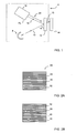
- FIG. 1 illustrates a simplified pictorial plan view of an illumination arrangement 6, including a recycling subsystem 18, providing light to a display 14, in accordance with an embodiment of the present invention-
- a light source 8 may be optically coupled to a transflective color filter 12, such that at least a portion of the light produced by the light source 8 is received by the transflective color filter 12.
- the transflective color filter 12 may then transmit portions of the light to the display 14 while reflecting other portions.
- the recycling subsystem 18 may be optically coupled to the transflective color filter 12, such that it receives the reflected light. The reflected light may then recycled by the recycling subsystem 18 and reintroduced to the transflective color filter 12.
- the light source 8 may be of a conventional design or any other design depending on the particular application.
- the light source 8 may include an arc lamp mounted at the focus of an elliptical reflector.
- An optional meniscus lens (not shown) may be placed between the elliptical reflector and the transflective color filter 12 to concentrate the light and reduce the cone angle.
- Embodiments of this invention could employ either converging (shown) or diverging light sources to accommodate for the downstream optical configuration.
- the white light may propagate along an incidence axis 10 and impinge upon the face of the transflective color filter 12 with an incidence angle ⁇ .
- the transflective color filter 12 may transmit light within certain passbands 13 while reflecting light outside of these passbands 16.
- the transmitted light 13 may illuminate the display 14.
- the reflected light may travel along a reflectance axis 16 towards the input 18a of the recycling subsystem 18.
- the input 18a may be located on the reflectance axis 16, which is non-coincident with the incident axis 10, so that the optical components required to collect the reflected light do not interfere with the incident light.
- the reflectance axis 16 and the incident axis 10 intersect at the face of the transflective color filter 12.
- the recycling subsystem 18 may redirect the reflected light back towards the transflective color filter 12 as recycled light along a recycling axis 20.
- the recycling axis 20 i.e., the axis upon which the recycled light is reintroduced to the transflective color filter 12 may be coincident with the reflectance axis 16, the incident axis 10, or neither axis depending on the properties of the recycling subsystem.
- some of the recycled light 20 may be transmitted through to the display 14.
- the recycled light 20 may exit through the recycling subsystem input 18a, however other embodiments could provide separate input and outputs for the recycling subsystem 18.
- the angular intensity distribution i.e., the angular spread of the light transmission as a function of the incident angle ⁇ , produced by the light source 8 into the entrance pupil of the projection lens may look like two elongated hot spots above one another.
- the upper hot spot may come from the light from the incident axis 10, while the lower hot spot may be the light recycled back along the reflectance axis 20.
- the light is spread over horizontal directions orthogonal to the two vertically aligned spots (such a horizontal line can be regarded as a line going through the plane of the page in the figures).
- the two hot spots correspond to a central area with an average incident angle ⁇ close to perpendicular to the display 14.
- the transflective color filter 12 and display 14 are properly selected and positioned, this elliptical spreading property of the illumination can be exploited to improve the efficiency of the system.
- the display 14 includes a digital micromirror device we can make use of the non-symmetrical pupil filling by appropriate alignment of the tilt direction of the micromirrors, which often limits the pupil size in one direction (in order to get high contrast).
- the pupil asymmetry may be matched with the direction orthogonal to the mirror's tilt direction to take advantage of this property.
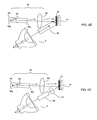
- FIGs. 2A and 2B show a diagram of light produced by a scrolling transflective color filter 12 as it might be focused on the display 14, in accordance with one embodiment of this invention.
- a light field 26 may comprise scrolling bands of multiple colors, e.g., primary colors, which correspond to the segments of the scrolling transflective color filter 12.
- the light field 26 is segmented into three bands, a red band 28 , a green band 30, and a blue band 32.
- the bands move across the light field so that in Fig. 2b , which shows the same light field 26 at a later time, the bands have moved down the light field.
- the blue band 32 has scrolled partially off the bottom of the light field and has partially reappeared at the top. This approach allows all but a few of the rows of the display to be illuminated almost constantly. Only the rows that are changing to the next color do not contribute to the image.
- Black bands (not shown) can be placed between the colored bands to prevent rows that are changing from affecting the display 14.
- the transflective color filter 12 may be used to synchronize the light source with the scrolling display 14 in order to illuminate each row of the display 14 with the appropriate color at the appropriate time.
- Examples of transflective color filters 12 that may be suitable for this type of application include but are not limited to rotating prisms, a rotating color drum, a sequential color recapture wheel, and a band modulation filter. They all have the characteristic that a number of colors, usually the three primary ones, e.g., red, green and blue, may be transmitted at one time to the display 14.
- Fig. 3 shows a cross-sectional view of the transflective color filter 12 in accordance with one embodiment of this invention.
- the transflective color filter 12 includes a red color passband 36, a green color passband 38 and a blue color passband 40. These color passbands allow a range of frequencies corresponding to a particula r color to pass through the filter while reflecting the frequencies outside of these ranges.
- White light 42 traveling along the incidence axis, strikes the face of the transflective color filter 12.
- the red passband 36 may transmit light in the red color band 44 and reflect cyan light 46, or a combination of blue and green.
- the green passband 38 may transmit light in the green color band 48 and reflect magenta light 50, a combination of blue and red.
- the blue passband 40 may transmit the light in the blue color band 52 and reflect yellow light 54, a combination of red and green.
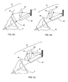
- Fig. 4 is a simplified pictorial plan view of multiple variations of an illumination arrangement, including an optical integrator in the color recycling path, providing light to a display, in accordance with embodiments of this invention.
- a light source 8 similar to the one discussed with relation to Fig. 1 , causes incident light to impinge upon the transflective color filter 12. Portions of the light containing color wavelengths that match the associated color passband are transmitted, while wavelengths outside of these passbands are reflected along the reflectance axis toward the recycling subsystem 18.
- R,G,B passbands, C,M,Y may be the respective reflected light.
- the recycling subsystem 18 of this embodiment may include an optical element 60 at its input, an optical integrator 58, and a mirror 62.
- the reflected light is imaged by the optical element 60 onto an opening aperture 58a at the first end of an optical integrator 58.
- the optical integrator 58 of this embodiment may be a solid glass light-integrating tunnel, which integrates the reflected light through total internal reflection.
- This tunnel integrator 58 may have a mirror 62 positioned at or near the second end 58b of the tunnel.
- a mirror may be a ny type of reflective surface or coating that reflects the appropriate wavelengths-
- the mirror 62 may be a separate optical component or it may be a coating applied to the second end 58b of the tunnel. The mirror will redirect the light back towards the opening aperture 58a.
- the bands of C,M,Y light may become sufficiently integrated as they travel twice the length of the tunnel before exiting.
- the recycled integrated light may pass back through the optical element 60 to be reintroduced to the transflective color filter 12, giving the light a second opportunity to be transmitted.
- the opening aperture 58a of the recycling integrator 58 may receive the reflected light directly from the transflective color filter 12, without going through the optical element 60.
- the incident light from the light source 8 is not integrated, which may be useful in video projection systems, as the perceived brightness is larger with the increased center peak brightness.
- the homogenized recycled light may then increase the intensity in the corners.
- Fig. 4b depicts an embodiment that includes an optical integrator 56 on the incident light path.
- This optical integrator 56 may be an integrating tunnel that has a tapered cross-sectional area to suit particular applications.
- a typical tunnel has a rectangular cross-section and is either straight or smaller at its entrance near the light source and larger at its exit.
- An output aperture of the optical integrator 56 may have an aspect ratio that matches the downstream display's aspect ratio, that is, the ratio between the width and the height of the image.
- this embodiment describes a glass rod integrator, other embodiments of this invention may use a double flyseye lens integrator or any other sufficiently effective integration device that provides a substantially uniform light distribution upon exiting the integrator.
- outlet apertures of the optical integrator 56 may have a cross-sectional aspect ratio that provides a projection display format that is compatible with conventional display standards.
- display standards include SVGA (Super Video Graphics Array), XGA (Extended Graphics Array), UXGA (Ultra XGA), WUXGA (Widescreen Ultra XGA), and HDTV (High Definition Television). These display standards are often a combination of resolution, color depth measured in bits, and refresh rate measured in hertz.
- SVGA, XGA, and UXGA all have aspect ratios of 4:3.
- HDTV has an aspect ratio of 16:9 and WUXGA is 16:10.
- Fig. 4c depicts an embodiment similar to the one discussed in Fig.
- Fig 5 is a simplified pictorial plan view of various embodiments of an illumination arrangement, including a color recycling path that coup les the reflected light back into the incident light path.
- the recycling subsystem 18 recycles the reflected light by coupling it back into the optical integrator 56 on th e incident axis using a series of reflective devices 64 and 68.
- the recycling subsystem 18 takes advantage of the 'hole' in the center of the illumination from the light source 8.
- Arc lamp illumination often has a "hole in the middle” effect due to arc lamp shadowing off of the elliptical reflector.
- This embodiment utilizes that effect by placing a small reflector 68 in the "hole” to re-introduce the recycled light into the optical integrator 56 on the incident axis, and ultimately the transflective color filter 12.
- the light may be continually recycled through the recycling subsystem until it is transmitted to the display 14.
- specifically designed optics may be used to optimize the angular properties of the recycled beam for to increase the amount of recycled light.
- FIG. 5b An alternative embodiment, depicted in Fig. 5b , shows the reflector 68 being placed close to the entrance of the optical integrator 56, only slightly reducing the amount of entrance light from the light source 8.
- FIG. 5c The embodiment depicted in Fig. 5c is similar to Fig. 5b , however the recycling subsystem 18 includes an optical integrator 57 to integrate the light reflected by the transflective color filter 12.
- the optical integrator 57 may also be incorporated into the Fig. 5a embodiment.
- the embodiments depicted by Fig. 5 show that the reflected light is coupled back into the integrator 56 through the end of the integrator 56.
- the integrator 56 is a solid glass tunnel, it may be possible to introduce the light through the sides of the tunnel as well.
- Fig. 6 is a simplified pictorial plan view of an illumination arrangement, including a color recycling subsystem 18 with a relay optical arrangement 74 and a mirror 82, providing light to a display 14, in accordance with one embodiment of this invention.
- the embodiment depicts a relay optical arrangement 74 with various sections that are involved in both the incident and reflectance paths.
- the light source 8 directs light into an optical integrator 56, such as a tunnel discussed above, which integrates the light and gives it a desired cross-sectional shape.
- the light exiting the tunnel 56 may be substantially telecentric due to the design of the light tunnel.
- any other source of telecentric or non-telecentric illumination can be used instead of the light source/tunnel combination discussed in this embodiment.
- Light from the tunnel 56 may enter an imaging lens 72 and then a relay optical arrangement 74, consisting of a relay lens in this embodiment.
- the two lenses 72 and 74 may be designed to create a telecentric image of the illumination from the light source at the display.
- the imaging lens 72 makes an intermediate image of the light source at an intermediate position 76 between the two lenses 72 and 74.
- the relay lens 74 then creates an image of the output of the tunnel 56 onto the display 14, with the intermediate pupil 76 imaged at infinity.
- Appropriate modifications can be made to the optical arrangement to accommodate the differences in light sources, optical integrators, or display sizes of various embodiments.
- lenses 72 and 74 may be singular or multiple optical components of various types, as appropriate.
- the lenses may be conventional spherical lenses.
- various aspheric, diffractive, or Fresnel surfaces may be included as may be desired to achieve cost and size goals for the system.
- Prisms, mirrors, and additional corrective elements may also be added as appropriate to fold, bend or modify the illumination light for the intended application.
- the imaging lens 72 has a focal length f1 that equals the distance from its focal plane to the exit aperture of the tunnel 56. Accordingly, it makes a lamp image and has its exit pupil at the position 76 that is a distance f1 away.
- the first section of the relay lens 78 has a focal length of f2 and is placed at that distance, f2, from the intermediate position 76 and from the display 14.
- the first section of the relay lens 78 re-images the pupil from the imaging lens 72, i.e. the lamp image at intermediate position 76, at infinity for telecentric illumination at the display 14.
- the first section 78 may be designed to image the exit aperture of the tunnel 56 at the display 14. Light travelling from the first section 78 to the display 14 will do so along an incident axis, similar to the one described with reference to Fig. 1 .
- the imaging lens 72 is centered on the tunnel 56 .
- the optical axis of the imaging lens 72 is aligned with the center of the tunnel 56 , however, other configurations are possible.
- the relay lens 74 may be de-centered with respect to the tunnel 56 and light source 8. This causes the illumination at the display 14 to be off-axis, filling half the system's Étendue.
- the relay lens 74 is decentered to the point that its optical axis is near the edge of or completely outside of the optical path of the image of the source 8. This decentering allows for the input to the recycling subsystem 18 to lie on a different axis then the incident axis.
- the relay lens 74 is, however, roughly centered about the display 14 as is shown in Fig. 6 . This means that the light from the light source 8 arrives at the imaging lens 72 decentered with respect to the display 14 but the relay lens 74 centers the image of the light on the display 14.
- the lenses need not be exactly centered with respect to the tunnel 56 or the display 14, as shown in the figures. Each one can be moved slightly if the other is so adjusted. In addition, if the transflective color filter 12 is placed at an angle then the relay lens 74 can be moved accordingly.
- the placement of the lenses in the illustrated embodiment may reduce the dimensions of the optical arrangement, however, the elements can be moved in a variety of different ways to meet particular size and form factor constraints of a specific embodiment.
- the recycling subsystem 18 consists of a second section of the relay lens 80 and a mirror 82.
- the second section of the recycling optical arrangement has a focal length equal to the first section f2.
- the mirror 82 may be placed at the imaging focus of the second section of the relay lens 80, which is directly above the intermediate focus discussed earlier.
- the two sections of the relay optical arrangement 74 could have different focal lengths, and therefore the mirror 82 positioning would be adjusted accordingly.
- the two sections of the relay lens 74 do not have to be mutually exclusive, as there can be some overlap as shown in the figure.
- the incident axis for certain light rays may pass through the same area of the relay lens 74 as the reflectance axis for other light rays.
- each particular light ray will travel from the first section of the relay lens 78 on its incident axis, and will travel to the second section of the relay lens 80 on its reflectance axis. This will be possible by keeping the angle of incidence, ⁇ , less than 90 degrees. This can be done by providing the origin of the incident axis below the point that the incident axis intersects with the transflective color filter 12, as shown with the off-lens construction described above. This may also be accomplished by tilting the transflective color filter 12.
- the mirror 82 may be tilted slightly such that it will reflect the C,M,Y bands along a different trajectory back towards the second section of the relay lens 80. Therefore, the second section of the relay lens 80 will reintroduce the C,M,Y bands to the transflective color filter 12 at an area different than they were originally reflected from. Reintroduction at a different section of the transflective color filter 12 may result in an increase in transmitted light through the passbands.
- the mirror 82 may be designed such that light rays reflected from the bottom portion of the transflective color filter 12 will be reflected from the mirror 82 at an upward angle so that the light is reintroduced near the top portion of the transflective color filter 12.
- specific calibration methods known in the art may be employed to increase the efficiencies of a particular optical architecture.
- Fig. 7 is a simplified pictorial plan view of an illumination arrangement, including a color recycling subsystem with an optical integrator 92, providing light to a display 14, in accordance with an embodiment of this invention.
- the functionality of the illumination arrangement is similar to Fig. 6 , however, the mirror 82 is replaced with a fold mirror 86, a lens 88, and an optical integrator 92.
- the optical integrator 92 may be similar to the optical integrator 58 in Fig. 4 .
- the lens 88 may focus the C,M,Y color bands on the input aperture of the optical integrator 90.
- a mirror 94 may be placed at or near the far end of the optical integrator 92 so that light is redirected back substantially along the original recycling trajectory until the integrated light is reintroduced on the transflective color filter 12. Portions of the recycled integrated light may be transmitted through the passbands of the transflective color filter 12 and impinge upon the display 14.
- Fig. 8 depicts an embodiment of this invention that combines both polarization recovery and color recycling.
- This embodiment may contain a similar optical architecture as Fig. 6 , however, this embodiment permits polarization recycling by the addition of a transflective polarizer 98, mirror 102, and a quarter wave plate 104.
- One polarization state (usually P-polarization) may be transmitted through the transflective polarizer 98 to the transflective color filter 14.
- P-polarized light rays are indicated in the drawing figures by short-length transverse lines intersecting a line representing a light propagation path. The lines suggest a polarization vector that is vertically aligned in the plane of the drawing sheet.
- the other polarization state (usually S-polarization) is reflected towards a mirror 102.
- S-polarized light rays are indicated in the drawing figures by small open circles connected together by a line representing a light propagation path. The circles suggest a polarization vector normal to the plane of the drawing sheet.
- the mirror 102 may then reflect the S-polarized light back to the transflective polarizer 98, which may reflect it in the direction of the source. With the off-set lens construction it may pass through a quarter wave plate 104 that rotates the polarization direction to substantially the P-polarization, and may then be reflected by a mirror 82 back toward the transflective polarizer 98 where it may be transmitted to the transflective color filter 12.
- the quarter wave plate 104 or some other polarization conversion device may be placed anywhere between the mirror 82 and the transflective polarizer 98. This could also be a quarter-wave film or coating placed on the mirror.
- the system could include a polarizing analyzer behind the display, such as an iodine-based PVA (poly-vinyl alcohol) film, or a wire grid polarizer to filter out any stray S-polarized light, enhancing contrast. Analyzers and polarizing filters may also be placed in other locations of the system as may be appropriate for a particular application or illumination system.
- the transflective polarizer 98 may be, e.g. a prism-type or a plate-type polarizing beam splitter, or any other type of device which will allow substantially all the light of one polarization state to pass, while reflecting substantially all the light of another, substantially perpendicular, polarization state.
- the plate-type PBS include, but are not limited to, a wire-grid polarizer, a cholesteric polarizer, a polymer film stack, or a dielectric coating stack.
- transflective polarizers and polarizing beam splitters may have angular dependent transmissive ranges that differ between orthogonal axes. In one axis, e.g. the horizontal, a greater range of incident light angles may be transmitted than in the other orthogonal axis, e.g. the vertical.
- the elliptical hotspot properties discussed above may be exploited by properly positioning the polarizing materials so that the axis of the greater angular transmission characteristic or the greater angular acceptance is aligned with the angular intensity distribution of the illumination. Stated another way, the transmissivity of the system is improved by matching the direction of the elongation of the hot spots to the direction of the high contrast isocontrast curve of the particular polarizer. This may increase efficiency that may be accompanied by a commensurate increase in brightness and contrast.
- Fig. 9 is a simplified pictorial plan view of a system including a video unit 110 coupled to a projection system 112, in accordance with an embodiment of the present invention.
- a video unit 110 transmits video signals to the projection system 112, which includes image projection optics 114 and an illumination arrangement 116.
- the illumination arrangement 116 may be similar to any one of the various embodiments described under the teachings of this invention.
- the image projection optics 114 may include a transmissive liquid crystal light valve arrangement coupled to a projection lens, to image the light valve on a screen.
- the image projection optics 114 could include reflective, rather than transmissive displays.
- the video unit 110 may include a personal or laptop computer, DVD, set-top box (STB), video camera, video recorder, or any other suitable device to transmit video signals to the projector.
- the system may be used as a projector for computer generated slides and for digital sourced imagery; however, many other applications such as games, movies, television, advertising and data display can be made.
Landscapes
- Physics & Mathematics (AREA)
- General Physics & Mathematics (AREA)
- Optics & Photonics (AREA)
- Astronomy & Astrophysics (AREA)
- Spectroscopy & Molecular Physics (AREA)
- Engineering & Computer Science (AREA)
- Multimedia (AREA)
- Signal Processing (AREA)
- Projection Apparatus (AREA)
- Video Image Reproduction Devices For Color Tv Systems (AREA)
- Internal Circuitry In Semiconductor Integrated Circuit Devices (AREA)
- Window Of Vehicle (AREA)
- Jib Cranes (AREA)
- Non-Portable Lighting Devices Or Systems Thereof (AREA)
Claims (25)
- Vorrichtung, die umfasst:eine Lichtquelle (8) zum Erzeugen von Licht;einen transflektiven Farbfilter (12), der mit der Lichtquelle (8) optisch verbunden ist, um das Licht entlang einer Einfallsachse zu empfangen, wobei der transflektive Farbfilter (12) wenigstens ein Farbdurchlassband enthält, um wenigstens einen Teil des Lichts in einem Frequenzbereich zu übertragen und wenigstens einen Teil des Lichts außerhalb des Frequenzbereichs entlang einer Reflexionsachse zu reflektieren, wobei die Einfalls- und Reflexionsachsen nicht übereinstimmen;ein Rückgewinnungsuntersystem (18), das mit dem transflektiven Farbfilter (12) optisch verbunden ist, das eine Eingabe (80), die auf der Reflexionsachse positioniert ist, und eine Ausgabe aufweist, wobei das Rückgewinnungsuntersystem (18) vorgesehen ist, das reflektierte Licht durch die Eingabe (80) zu empfangen und zurückgewonnenes Licht durch die Ausgabe zum transflektiven Farbfilter (12) zu emittieren;eine Anzeige (14), die mit dem transflektiven Farbfilter (12) optisch verbunden ist, um das übertragene Licht von dem transflektiven Farbfilter (12) zu empfangen, wobei die Anzeige (14) im Wesentlichen auf einer optischen Achse zentriert ist;eine optische Relaisanordnung (78), die im Wesentlichen auf einer ersten Seite der optischen Achse der Anzeige positioniert ist, um das Licht von der Lichtquelle (8) zu empfangen und das Licht entlang der Einfallsachse zum transflektiven Farbfilter (12) zu übertragen; undwobei die Eingabe (80) des Rückgewinnungsuntersystems (18) auf einer zweiten Seite der optischen Achse der Anzeige (14) angeordnet ist.
- Vorrichtung nach Anspruch 1, bei welcher der transflektive Farbfilter (12) einer aus einer Gruppe ist, die aus einer sich drehenden Farbtrommel, einem sich drehenden Spiralfarbrad und einem Bandmodulationsfilter besteht.
- Vorrichtung nach Anspruch 1, bei welcher der transflektive Farbfilter (12) wenigstens eines aus einer Gruppe enthält, die aus einem roten, einem grünen und einem blauen Durchlassband besteht.
- Vorrichtung nach Anspruch 1, bei der die Anzeige (14) ein durchlässiges Flüssigkristall-Lichtventil ist.
- Vorrichtung nach Anspruch 1, ferner umfassend:eine Relaislinse (74), die im Wesentlichen auf der optischen Achse der Anzeige (14) zentriert ist; und wobeisowohl die Eingabe (80) des Rückgewinnungsuntersystems (18) als auch die optische Relaisanordnung (78) Bereiche der Relaislinse (74) enthalten.
- Vorrichtung nach Anspruch 1, ferner umfassend:einen optischen Integrator (56) zum Empfangen von Licht von der Lichtquelle (8) und Übertragen des Lichts zu einer Bildlinse (72), wobei die Bildlinse (72) vorgesehen ist, das Licht zur optischen Relaisanordnung (78) zu übertragen.
- Vorrichtung nach Anspruch 1, bei der das Rückgewinnungsuntersystem (18) ferner
einen ersten Spiegel (82, 94) zum Empfangen eines Teils des reflektierten Lichts von der Eingabe (80) des Rückgewinnungsuntersystems (18) und zum Umlenken desselben zur Eingabe (80) des Rückgewinnungsuntersystems (18) umfasst; und wobei
die Eingabe (80) des Rückgewinnungsuntersystems (18) im Wesentlichen gleich der Ausgabe des Rückgewinnungsuntersystems (18) ist. - Vorrichtung nach Anspruch 7, bei der das Rückgewinnungsuntersystem (18) ferner
einen optischen Integrator (92) umfasst, der ein erstes Ende zum Empfangen des Lichts von der Eingabe (80) des Rückgewinnungsuntersystems (18) aufweist; und wobei
der erste Spiegel (94) auf oder in der Nähe eines zweiten Endes des optischen Integrators (92) angeordnet ist, um das Licht durch den optischen Integrator (92) zum ersten Ende zurückzureflektieren. - Vorrichtung nach Anspruch 8, bei der das Rückgewinnungsuntersystem (18) ferner umfasst:einen Umlenkungsspiegel (86) zum Empfangen des Lichts von der Eingabe (80) des Rückgewinnungsuntersystems (18) und zum Reflektieren des Lichts zu einer Bildlinse (88), wobei die Bildlinse (88) vorgesehen ist, das Licht an dem ersten Ende des optischen Integrators (92) abzubilden.
- Vorrichtung nach Anspruch 7, bei welcher der erste Spiegel (82, 94) so geneigt ist, dass das Licht auf einem anderen Weg zur Eingabe (80) des Rückgewinnungsuntersystems (18) umgelenkt wird.
- Vorrichtung nach Anspruch 7, ferner umfassend:einen zweiten Spiegel (102);einen transflektiven Polarisator (98), um Licht von der optischen Relaisanordnung (78) zu empfangen, zum Übertragen von Licht in einem ersten Polarisationszustand zum transflektiven Farbfilter (12) und zum Reflektieren von Licht in einem zweiten Polarisationszustand zum zweiten Spiegel (102);wobei der zweite Spiegel (102) angepasst ist, Licht in dem zweiten Polarisationszustand zum transflektiven Polarisator (98) zurückzureflektieren, was Licht zur Folge hat, das von dem transflektiven Polarisator (98) zur Eingabe (80) des Rückgewinnungsuntersystems (18) wegreflektiert wird; undein λ-Viertel-Plättchen (104) zwischen dem ersten Spiegel (82, 94) und der Eingabe (80) des Rückgewinnungsuntersystems (18), um Licht in dem zweiten Polarisationszustand in den ersten Polarisationszustand zu überführen.
- Vorrichtung nach Anspruch 11, bei der das λ-Viertel-Plättchen (104) eine Beschichtung auf dem ersten Spiegel (82, 94) umfasst.
- Vorrichtung nach Anspruch 1, ferner umfassend
einen ersten optischen Integrator (56), der eine Eingabe- und Ausgabeöffnung enthält, wobei die Eingabeöffnung vorgesehen ist, um Licht von der Lichtquelle (8) zu empfangen, und die Ausgabeöffnung vorgesehen ist, um Licht zum transflektiven Farbfilter (12) zu übertragen. - Vorrichtung nach Anspruch 13, bei der das Rückgewinnungsuntersystem (18) ferner
einen zweiten optischen Integrator (92) umfasst, der ein erstes Ende aufweist, um das reflektierte Licht von dem transflektiven Farbfilter (12) zu empfangen. - Vorrichtung nach Anspruch 14, bei der das Rückgewinnungsuntersystem (18) einen Spiegel (94) enthält, der an oder in der Nähe eines zweiten Endes des zweiten optischen Integrators (92) angeordnet ist, um Licht durch den zweiten optischen Integrator (92) zum ersten Ende zurück und zum transflektiven Farbfilter (12) heraus zu reflektieren.
- Vorrichtung nach Anspruch 15, bei der das Rückgewinnungsuntersystem (18) ein optisches Element zum Abbilden des reflektierten Lichts von dem transflektiven Farbfilter (12) an dem ersten Ende des zweiten optischen Integrators (82) enthält.
- Vorrichtung nach Anspruch 13, bei der die Ausgabe des Rückgewinnungsuntersystems (18) mit dem ersten optischen Integrator (56) optisch verbunden ist.
- Verfahren, das umfasst:Erzeugen von Licht von einer Lichtquelle (8);Empfangen des Lichts von der Lichtquelle (8) und Übertragen des Lichts zu einem transflektiven Farbfilter (12) entlang einer Einfallsachse des transflektiven Farbfilters (12), wobei eine optische Relaisanordnung (80) im Wesentlichen auf einer ersten Seite einer optischen Achse einer Anzeige (14) positioniert ist, wobei die Anzeige (14) im Wesentlichen auf der optischen Achse zentriert ist;Empfangen des Lichts entlang der Einfallsachse mit dem transflektiven Farbfilter (12), Übertragen von Licht innerhalb eines Frequenzbereichs zu der Anzeige (14) und Reflektieren von Licht, das sich außerhalb des Frequenzbereichs befindet, entlang einer Reflexionsachse, welche mit der Einfallsachse nicht übereinstimmt;Empfangen des reflektierten Lichts durch eine Eingabe des Rückgewinnungsuntersystems (18), wobei die Eingabe auf der Reflexionsachse und auf einer zweiten Seite der optischen Achse der Anzeige (14) positioniert ist; und wobeidas Rückgewinnungsuntersystem (18) das reflektierte Licht durch Einbringen desselben in den transflektiven Farbfilter (12) zurückgewinnt.
- Verfahren nach Anspruch 18, bei dem das Zurückgewinnen des reflektierten Lichts ein Integrieren des reflektierten Lichts vor dem Einbringen desselben in den transflektiven Farbfilter (12) enthält.
- Verfahren nach Anspruch 18, bei dem das Zurückgewinnen des reflektierten Lichts ein abermaliges Einbringen des Lichts entlang einer Rückgewinnungsachse enthält, welche mit der Reflexionsachse nicht übereinstimmt.
- Verfahren nach Anspruch 20, ferner umfassend
Übertragen von Licht einer Polarisationsrichtung zum transflektiven Farbfilter (12);
Reflektieren von Licht einer zweiten Polarisationsrichtung; und
Zurückgewinnen des Lichts einer zweiten Polarisationsrichtung durch Überführen desselben in die erste Polarisationsrichtung und Übertragen desselben zum transflektiven Farbfilter (12). - Verfahren nach Anspruch 20, bei dem die Rückgewinnungsachse im Wesentlichen mit der Einfallsachse übereinstimmt.
- Verfahren nach Anspruch 22, ferner umfassend ein Integrieren des Lichts, das sich entlang der Einfallsachse bewegt.
- Vorrichtung nach einem der Ansprüche 1 bis 17, ferner umfassend:eine Videoeinheit (110) mit einem Ausgabevideosignal; undein Projektionssystem (112), das mit der Videoeinheit (110) verbunden ist, um das Videosignal zu empfangen und das Video zu projizieren, wobei das Projektionssystem (112) die Lichtquelle (8), die optische Relaisanordnung (78), den transflektiven Farbfilter (12), die Anzeige (14) und das Rückgewinnungsuntersystem (18) enthält.
- Vorrichtung nach Anspruch 24, in der die Videoeinheit (110) aus einer DVD, einer Videokamera oder einem Digitalempfänger ausgewählt ist.
Applications Claiming Priority (2)
| Application Number | Priority Date | Filing Date | Title |
|---|---|---|---|
| US10/804,661 US7144133B2 (en) | 2002-05-17 | 2004-03-18 | Transflective color recovery |
| PCT/US2005/007133 WO2005091647A1 (en) | 2004-03-18 | 2005-03-03 | Transflective color recovery |
Publications (2)
| Publication Number | Publication Date |
|---|---|
| EP1726164A1 EP1726164A1 (de) | 2006-11-29 |
| EP1726164B1 true EP1726164B1 (de) | 2010-11-03 |
Family
ID=34827700
Family Applications (1)
| Application Number | Title | Priority Date | Filing Date |
|---|---|---|---|
| EP05724640A Expired - Lifetime EP1726164B1 (de) | 2004-03-18 | 2005-03-03 | Transflektive farb-recovery |
Country Status (7)
| Country | Link |
|---|---|
| US (1) | US7144133B2 (de) |
| EP (1) | EP1726164B1 (de) |
| JP (1) | JP4877226B2 (de) |
| CN (2) | CN100588266C (de) |
| AT (1) | ATE487331T1 (de) |
| DE (2) | DE602005024524D1 (de) |
| WO (1) | WO2005091647A1 (de) |
Families Citing this family (14)
| Publication number | Priority date | Publication date | Assignee | Title |
|---|---|---|---|---|
| US7733443B2 (en) | 2004-03-09 | 2010-06-08 | Nitto Denko Corporation | LCD comprising backlight and reflective polarizer on front panel |
| US7456915B2 (en) * | 2004-03-26 | 2008-11-25 | Nitto Denko Corporation | Liquid crystal display panel with broadband interference polarizers |
| KR100881667B1 (ko) | 2006-10-19 | 2009-02-06 | 삼성전자주식회사 | 되반사형 라이트파이프, 이를 채용한 균일광 조명장치 및화상투사장치 |
| US7845822B2 (en) * | 2006-12-29 | 2010-12-07 | Koninklijke Philips Electronics N.V. | Illumination device including a color selecting panel for recycling unwanted light |
| DE102007055443B4 (de) * | 2007-11-20 | 2010-09-23 | Carl Zeiss Smt Ag | Projektionsbelichtungsanlage für die Mikrolithographie |
| KR100933282B1 (ko) * | 2008-01-16 | 2009-12-22 | 연세대학교 산학협력단 | 색채 복원 방법 및 시스템 |
| WO2009119370A1 (ja) * | 2008-03-26 | 2009-10-01 | コニカミノルタオプト株式会社 | 撮像装置 |
| US8310408B1 (en) * | 2008-11-12 | 2012-11-13 | Waveguide Consulting, Incorporated | System and method for graphical user interface and display among different aspect ratio video display devices |
| KR101050648B1 (ko) * | 2008-12-02 | 2011-07-19 | 삼성전자주식회사 | Dlp 프로젝션을 구비한 휴대용 통신 장치의 발광 장치 |
| WO2010090862A2 (en) * | 2009-01-21 | 2010-08-12 | Abu-Ageel Nayef M | Illumination system utilizing wavelength conversion materials and light recycling |
| US9140604B2 (en) | 2011-06-17 | 2015-09-22 | Kla-Tencor Corporation | Wafer level spectrometer |
| TWI450019B (zh) * | 2011-10-06 | 2014-08-21 | Acer Inc | 照明系統與投影裝置 |
| CN103091955B (zh) * | 2011-11-08 | 2017-09-01 | 宏碁股份有限公司 | 照明系统与投影装置 |
| DE102014113700A1 (de) * | 2014-09-23 | 2016-03-24 | Hella Kgaa Hueck & Co. | Scheinwerfer für Fahrzeuge |
Family Cites Families (36)
| Publication number | Priority date | Publication date | Assignee | Title |
|---|---|---|---|---|
| DE2216991A1 (de) * | 1972-04-08 | 1973-10-11 | Bosch Gmbh Robert | Polarisationsscheinwerfer |
| CH558023A (de) * | 1972-08-29 | 1975-01-15 | Battelle Memorial Institute | Polarisationsvorrichtung. |
| US5327270A (en) * | 1989-03-23 | 1994-07-05 | Matsushita Electric Industrial Co., Ltd. | Polarizing beam splitter apparatus and light valve image projection system |
| NL8901077A (nl) * | 1989-04-28 | 1990-11-16 | Koninkl Philips Electronics Nv | Optische belichtingsstelsel en projectie-apparaat voorzien van een dergelijk stelsel. |
| US5410370A (en) * | 1990-12-27 | 1995-04-25 | North American Philips Corporation | Single panel color projection video display improved scanning |
| JPH05196892A (ja) * | 1992-01-21 | 1993-08-06 | Canon Inc | 偏光照明装置及び該偏光照明装置を用いた投写型表示装置 |
| JPH07294919A (ja) * | 1994-04-27 | 1995-11-10 | Canon Inc | 投影装置 |
| DE69532660T2 (de) * | 1994-12-28 | 2005-02-10 | Seiko Epson Corp. | Polarisations-Beleuchtungsvorrichtung und diese verwendender Projektor |
| US5822021A (en) * | 1996-05-14 | 1998-10-13 | Colorlink, Inc. | Color shutter liquid crystal display system |
| US5751384A (en) * | 1995-05-23 | 1998-05-12 | The Board Of Regents Of The University Of Colorado | Color polarizers for polarizing an additive color spectrum along a first axis and it's compliment along a second axis |
| FR2733601B1 (fr) * | 1995-04-28 | 1997-06-27 | Thomson Multimedia Sa | Dispositif de separation de polarisation et application a un systeme d'eclairement d'un ecran a cristal liquide |
| JPH08340545A (ja) * | 1995-06-13 | 1996-12-24 | Matsushita Electric Ind Co Ltd | 投写型画像表示装置 |
| GB2306741A (en) * | 1995-10-24 | 1997-05-07 | Sharp Kk | Illuminator |
| US6331879B1 (en) * | 1995-11-20 | 2001-12-18 | Minolta Co., Ltd. | Liquid crystal projector with an illumination optical system |
| JPH10186282A (ja) * | 1996-11-11 | 1998-07-14 | Sharp Corp | 投影型画像表示装置 |
| TW372281B (en) * | 1996-11-25 | 1999-10-21 | Koninkl Philips Electronics Nv | Illumination system and image projection device provided with such an illumination system |
| US6310713B2 (en) * | 1997-04-07 | 2001-10-30 | International Business Machines Corporation | Optical system for miniature personal displays using reflective light valves |
| JP2939237B2 (ja) * | 1997-04-09 | 1999-08-25 | 三星電子株式会社 | 反射型プロジェクター |
| TW358889B (en) * | 1997-10-20 | 1999-05-21 | Ind Tech Res Inst | High-efficiency light source polarizing converter |
| US6341867B1 (en) * | 1998-02-18 | 2002-01-29 | Seiko Epson Corporation | Polarized light illumination device and projector |
| US5900976A (en) * | 1998-02-20 | 1999-05-04 | Displaytech, Inc. | Display system including a polarizing beam splitter |
| US6064523A (en) * | 1998-06-29 | 2000-05-16 | International Business Machines Corporation | Apparatus for polarization conversion |
| US6266105B1 (en) * | 1998-07-31 | 2001-07-24 | Philips Electornics North America Corporation | Color projection system incorporation electro-optic light modulator and rotating light-reflective element |
| US6084703A (en) * | 1999-01-11 | 2000-07-04 | Texas Instruments Incorporated | Illumination system for high resolution display systems |
| US6278552B1 (en) * | 1999-05-12 | 2001-08-21 | Minolta Co., Ltd. | Polarization separation device and projection-type display apparatus |
| JP3328238B2 (ja) * | 1999-08-27 | 2002-09-24 | エヌイーシービューテクノロジー株式会社 | 単板反射型素子を用いた高輝度プロジェクタ |
| ATE478523T1 (de) * | 1999-11-05 | 2010-09-15 | Texas Instruments Inc | Sequentielle fabrückgewinnung für projektionssysteme |
| US7052150B2 (en) * | 1999-12-30 | 2006-05-30 | Texas Instruments Incorporated | Rod integrator |
| JP2001228535A (ja) * | 2000-02-14 | 2001-08-24 | Hitachi Ltd | 投写形表示装置 |
| US6227682B1 (en) * | 2000-03-22 | 2001-05-08 | Cogent Light Technologies, Inc. | Coupling of light from a small light source for projection systems using parabolic reflectors |
| US6499844B2 (en) * | 2000-05-01 | 2002-12-31 | Koninklijke Philips Electronics N.V. | Projection device and integrator plate suitable for such a projection device |
| US7230656B2 (en) * | 2000-11-30 | 2007-06-12 | Texas Instruments Incorporated | Sequential color filter |
| JP4628566B2 (ja) * | 2001-03-12 | 2011-02-09 | 三菱電機株式会社 | 画像投写装置 |
| US6739723B1 (en) * | 2001-12-07 | 2004-05-25 | Delta Electronics, Inc. | Polarization recapture system for liquid crystal-based data projectors |
| JP4078863B2 (ja) * | 2002-03-27 | 2008-04-23 | セイコーエプソン株式会社 | 照明装置およびカラーホイール |
| KR100839285B1 (ko) * | 2002-04-23 | 2008-06-17 | 엘지전자 주식회사 | 컬러드럼을 이용한 투사장치 |
-
2004
- 2004-03-18 US US10/804,661 patent/US7144133B2/en not_active Expired - Fee Related
-
2005
- 2005-03-03 EP EP05724640A patent/EP1726164B1/de not_active Expired - Lifetime
- 2005-03-03 AT AT05724640T patent/ATE487331T1/de not_active IP Right Cessation
- 2005-03-03 CN CN200580015584A patent/CN100588266C/zh not_active Expired - Fee Related
- 2005-03-03 JP JP2007503941A patent/JP4877226B2/ja not_active Expired - Fee Related
- 2005-03-03 WO PCT/US2005/007133 patent/WO2005091647A1/en not_active Ceased
- 2005-03-03 DE DE602005024524T patent/DE602005024524D1/de not_active Expired - Lifetime
- 2005-03-16 DE DE200520004297 patent/DE202005004297U1/de not_active Expired - Lifetime
- 2005-03-18 CN CNU2005200119515U patent/CN2911712Y/zh not_active Expired - Lifetime
Also Published As
| Publication number | Publication date |
|---|---|
| DE202005004297U1 (de) | 2005-07-28 |
| CN100588266C (zh) | 2010-02-03 |
| WO2005091647A1 (en) | 2005-09-29 |
| DE602005024524D1 (de) | 2010-12-16 |
| ATE487331T1 (de) | 2010-11-15 |
| CN2911712Y (zh) | 2007-06-13 |
| US20040174692A1 (en) | 2004-09-09 |
| JP2007529782A (ja) | 2007-10-25 |
| CN1977543A (zh) | 2007-06-06 |
| US7144133B2 (en) | 2006-12-05 |
| EP1726164A1 (de) | 2006-11-29 |
| JP4877226B2 (ja) | 2012-02-15 |
Similar Documents
| Publication | Publication Date | Title |
|---|---|---|
| US6666557B1 (en) | Reflection type projector | |
| US6827450B1 (en) | Scrolling color projection system | |
| CN1669066B (zh) | 具有反射镜和偏振转换器的偏振光源系统 | |
| US7452086B2 (en) | Light pipe based projection engine | |
| US7144133B2 (en) | Transflective color recovery | |
| JPH08271854A (ja) | 光源の像を投写する装置 | |
| JP2003519405A (ja) | シリコン上搭載液晶反射型投映エンジンアーキテクチャ | |
| US7131736B2 (en) | Efficient illumination systems for reduced étendue color video projection systems | |
| US7055967B2 (en) | Illumination systems employing corrective optics for use in reduced étendue color video projection systems | |
| JP2004118153A (ja) | 投写型表示装置 | |
| JP2008233252A (ja) | 投写型表示装置 | |
| US7303283B2 (en) | Projection type display | |
| CN100533260C (zh) | 图像显示光学系统和图像投影设备 | |
| US7374291B2 (en) | Projection optical system and image display apparatus using same | |
| US20050286144A1 (en) | Method and device for improving contrast in a projection system | |
| JPH046543A (ja) | 投写型表示装置および該装置に用いる色分解光学装置 | |
| CN101000408A (zh) | 全内反射棱镜 | |
| KR100482318B1 (ko) | 후면 투사장치의 컬러 스크롤링 장치 |
Legal Events
| Date | Code | Title | Description |
|---|---|---|---|
| PUAI | Public reference made under article 153(3) epc to a published international application that has entered the european phase |
Free format text: ORIGINAL CODE: 0009012 |
|
| 17P | Request for examination filed |
Effective date: 20060921 |
|
| AK | Designated contracting states |
Kind code of ref document: A1 Designated state(s): AT BE BG CH CY CZ DE DK EE ES FI FR GB GR HU IE IS IT LI LT LU MC NL PL PT RO SE SI SK TR |
|
| DAX | Request for extension of the european patent (deleted) | ||
| 17Q | First examination report despatched |
Effective date: 20080811 |
|
| GRAP | Despatch of communication of intention to grant a patent |
Free format text: ORIGINAL CODE: EPIDOSNIGR1 |
|
| RAP1 | Party data changed (applicant data changed or rights of an application transferred) |
Owner name: SEIKO EPSON CORPORATION |
|
| GRAS | Grant fee paid |
Free format text: ORIGINAL CODE: EPIDOSNIGR3 |
|
| GRAA | (expected) grant |
Free format text: ORIGINAL CODE: 0009210 |
|
| AK | Designated contracting states |
Kind code of ref document: B1 Designated state(s): AT BE BG CH CY CZ DE DK EE ES FI FR GB GR HU IE IS IT LI LT LU MC NL PL PT RO SE SI SK TR |
|
| REG | Reference to a national code |
Ref country code: GB Ref legal event code: FG4D |
|
| REG | Reference to a national code |
Ref country code: CH Ref legal event code: EP |
|
| REG | Reference to a national code |
Ref country code: IE Ref legal event code: FG4D |
|
| REF | Corresponds to: |
Ref document number: 602005024524 Country of ref document: DE Date of ref document: 20101216 Kind code of ref document: P |
|
| REG | Reference to a national code |
Ref country code: NL Ref legal event code: VDEP Effective date: 20101103 |
|
| LTIE | Lt: invalidation of european patent or patent extension |
Effective date: 20101103 |
|
| PG25 | Lapsed in a contracting state [announced via postgrant information from national office to epo] |
Ref country code: LT Free format text: LAPSE BECAUSE OF FAILURE TO SUBMIT A TRANSLATION OF THE DESCRIPTION OR TO PAY THE FEE WITHIN THE PRESCRIBED TIME-LIMIT Effective date: 20101103 |
|
| PG25 | Lapsed in a contracting state [announced via postgrant information from national office to epo] |
Ref country code: NL Free format text: LAPSE BECAUSE OF FAILURE TO SUBMIT A TRANSLATION OF THE DESCRIPTION OR TO PAY THE FEE WITHIN THE PRESCRIBED TIME-LIMIT Effective date: 20101103 Ref country code: SE Free format text: LAPSE BECAUSE OF FAILURE TO SUBMIT A TRANSLATION OF THE DESCRIPTION OR TO PAY THE FEE WITHIN THE PRESCRIBED TIME-LIMIT Effective date: 20101103 Ref country code: AT Free format text: LAPSE BECAUSE OF FAILURE TO SUBMIT A TRANSLATION OF THE DESCRIPTION OR TO PAY THE FEE WITHIN THE PRESCRIBED TIME-LIMIT Effective date: 20101103 Ref country code: PT Free format text: LAPSE BECAUSE OF FAILURE TO SUBMIT A TRANSLATION OF THE DESCRIPTION OR TO PAY THE FEE WITHIN THE PRESCRIBED TIME-LIMIT Effective date: 20110303 Ref country code: SI Free format text: LAPSE BECAUSE OF FAILURE TO SUBMIT A TRANSLATION OF THE DESCRIPTION OR TO PAY THE FEE WITHIN THE PRESCRIBED TIME-LIMIT Effective date: 20101103 Ref country code: FI Free format text: LAPSE BECAUSE OF FAILURE TO SUBMIT A TRANSLATION OF THE DESCRIPTION OR TO PAY THE FEE WITHIN THE PRESCRIBED TIME-LIMIT Effective date: 20101103 Ref country code: IS Free format text: LAPSE BECAUSE OF FAILURE TO SUBMIT A TRANSLATION OF THE DESCRIPTION OR TO PAY THE FEE WITHIN THE PRESCRIBED TIME-LIMIT Effective date: 20110303 Ref country code: BG Free format text: LAPSE BECAUSE OF FAILURE TO SUBMIT A TRANSLATION OF THE DESCRIPTION OR TO PAY THE FEE WITHIN THE PRESCRIBED TIME-LIMIT Effective date: 20110203 |
|
| PG25 | Lapsed in a contracting state [announced via postgrant information from national office to epo] |
Ref country code: GR Free format text: LAPSE BECAUSE OF FAILURE TO SUBMIT A TRANSLATION OF THE DESCRIPTION OR TO PAY THE FEE WITHIN THE PRESCRIBED TIME-LIMIT Effective date: 20110204 |
|
| PG25 | Lapsed in a contracting state [announced via postgrant information from national office to epo] |
Ref country code: EE Free format text: LAPSE BECAUSE OF FAILURE TO SUBMIT A TRANSLATION OF THE DESCRIPTION OR TO PAY THE FEE WITHIN THE PRESCRIBED TIME-LIMIT Effective date: 20101103 Ref country code: ES Free format text: LAPSE BECAUSE OF FAILURE TO SUBMIT A TRANSLATION OF THE DESCRIPTION OR TO PAY THE FEE WITHIN THE PRESCRIBED TIME-LIMIT Effective date: 20110214 Ref country code: CZ Free format text: LAPSE BECAUSE OF FAILURE TO SUBMIT A TRANSLATION OF THE DESCRIPTION OR TO PAY THE FEE WITHIN THE PRESCRIBED TIME-LIMIT Effective date: 20101103 Ref country code: BE Free format text: LAPSE BECAUSE OF FAILURE TO SUBMIT A TRANSLATION OF THE DESCRIPTION OR TO PAY THE FEE WITHIN THE PRESCRIBED TIME-LIMIT Effective date: 20101103 |
|
| PG25 | Lapsed in a contracting state [announced via postgrant information from national office to epo] |
Ref country code: PL Free format text: LAPSE BECAUSE OF FAILURE TO SUBMIT A TRANSLATION OF THE DESCRIPTION OR TO PAY THE FEE WITHIN THE PRESCRIBED TIME-LIMIT Effective date: 20101103 Ref country code: DK Free format text: LAPSE BECAUSE OF FAILURE TO SUBMIT A TRANSLATION OF THE DESCRIPTION OR TO PAY THE FEE WITHIN THE PRESCRIBED TIME-LIMIT Effective date: 20101103 Ref country code: SK Free format text: LAPSE BECAUSE OF FAILURE TO SUBMIT A TRANSLATION OF THE DESCRIPTION OR TO PAY THE FEE WITHIN THE PRESCRIBED TIME-LIMIT Effective date: 20101103 Ref country code: RO Free format text: LAPSE BECAUSE OF FAILURE TO SUBMIT A TRANSLATION OF THE DESCRIPTION OR TO PAY THE FEE WITHIN THE PRESCRIBED TIME-LIMIT Effective date: 20101103 |
|
| PLBE | No opposition filed within time limit |
Free format text: ORIGINAL CODE: 0009261 |
|
| STAA | Information on the status of an ep patent application or granted ep patent |
Free format text: STATUS: NO OPPOSITION FILED WITHIN TIME LIMIT |
|
| 26N | No opposition filed |
Effective date: 20110804 |
|
| PG25 | Lapsed in a contracting state [announced via postgrant information from national office to epo] |
Ref country code: MC Free format text: LAPSE BECAUSE OF NON-PAYMENT OF DUE FEES Effective date: 20110331 |
|
| REG | Reference to a national code |
Ref country code: CH Ref legal event code: PL |
|
| REG | Reference to a national code |
Ref country code: DE Ref legal event code: R097 Ref document number: 602005024524 Country of ref document: DE Effective date: 20110804 |
|
| PG25 | Lapsed in a contracting state [announced via postgrant information from national office to epo] |
Ref country code: IT Free format text: LAPSE BECAUSE OF FAILURE TO SUBMIT A TRANSLATION OF THE DESCRIPTION OR TO PAY THE FEE WITHIN THE PRESCRIBED TIME-LIMIT Effective date: 20101103 |
|
| REG | Reference to a national code |
Ref country code: IE Ref legal event code: MM4A |
|
| PG25 | Lapsed in a contracting state [announced via postgrant information from national office to epo] |
Ref country code: LI Free format text: LAPSE BECAUSE OF NON-PAYMENT OF DUE FEES Effective date: 20110331 Ref country code: IE Free format text: LAPSE BECAUSE OF NON-PAYMENT OF DUE FEES Effective date: 20110303 Ref country code: CH Free format text: LAPSE BECAUSE OF NON-PAYMENT OF DUE FEES Effective date: 20110331 |
|
| PG25 | Lapsed in a contracting state [announced via postgrant information from national office to epo] |
Ref country code: LU Free format text: LAPSE BECAUSE OF NON-PAYMENT OF DUE FEES Effective date: 20110303 Ref country code: CY Free format text: LAPSE BECAUSE OF FAILURE TO SUBMIT A TRANSLATION OF THE DESCRIPTION OR TO PAY THE FEE WITHIN THE PRESCRIBED TIME-LIMIT Effective date: 20101103 |
|
| PG25 | Lapsed in a contracting state [announced via postgrant information from national office to epo] |
Ref country code: TR Free format text: LAPSE BECAUSE OF FAILURE TO SUBMIT A TRANSLATION OF THE DESCRIPTION OR TO PAY THE FEE WITHIN THE PRESCRIBED TIME-LIMIT Effective date: 20101103 |
|
| PG25 | Lapsed in a contracting state [announced via postgrant information from national office to epo] |
Ref country code: HU Free format text: LAPSE BECAUSE OF FAILURE TO SUBMIT A TRANSLATION OF THE DESCRIPTION OR TO PAY THE FEE WITHIN THE PRESCRIBED TIME-LIMIT Effective date: 20101103 |
|
| REG | Reference to a national code |
Ref country code: FR Ref legal event code: PLFP Year of fee payment: 12 |
|
| PGFP | Annual fee paid to national office [announced via postgrant information from national office to epo] |
Ref country code: DE Payment date: 20160223 Year of fee payment: 12 |
|
| PGFP | Annual fee paid to national office [announced via postgrant information from national office to epo] |
Ref country code: GB Payment date: 20160302 Year of fee payment: 12 Ref country code: FR Payment date: 20160208 Year of fee payment: 12 |
|
| REG | Reference to a national code |
Ref country code: DE Ref legal event code: R119 Ref document number: 602005024524 Country of ref document: DE |
|
| GBPC | Gb: european patent ceased through non-payment of renewal fee |
Effective date: 20170303 |
|
| REG | Reference to a national code |
Ref country code: FR Ref legal event code: ST Effective date: 20171130 |
|
| PG25 | Lapsed in a contracting state [announced via postgrant information from national office to epo] |
Ref country code: FR Free format text: LAPSE BECAUSE OF NON-PAYMENT OF DUE FEES Effective date: 20170331 Ref country code: DE Free format text: LAPSE BECAUSE OF NON-PAYMENT OF DUE FEES Effective date: 20171003 |
|
| PG25 | Lapsed in a contracting state [announced via postgrant information from national office to epo] |
Ref country code: GB Free format text: LAPSE BECAUSE OF NON-PAYMENT OF DUE FEES Effective date: 20170303 |