EP1724439A2 - Procédé pour réaliser un disque de turbine à gaz ayant un gradient de composition - Google Patents
Procédé pour réaliser un disque de turbine à gaz ayant un gradient de composition Download PDFInfo
- Publication number
- EP1724439A2 EP1724439A2 EP06252482A EP06252482A EP1724439A2 EP 1724439 A2 EP1724439 A2 EP 1724439A2 EP 06252482 A EP06252482 A EP 06252482A EP 06252482 A EP06252482 A EP 06252482A EP 1724439 A2 EP1724439 A2 EP 1724439A2
- Authority
- EP
- European Patent Office
- Prior art keywords
- segment
- composition
- gas turbine
- radially outer
- turbine disk
- Prior art date
- Legal status (The legal status is an assumption and is not a legal conclusion. Google has not performed a legal analysis and makes no representation as to the accuracy of the status listed.)
- Withdrawn
Links
Images

Classifications
-
- F—MECHANICAL ENGINEERING; LIGHTING; HEATING; WEAPONS; BLASTING
- F01—MACHINES OR ENGINES IN GENERAL; ENGINE PLANTS IN GENERAL; STEAM ENGINES
- F01D—NON-POSITIVE DISPLACEMENT MACHINES OR ENGINES, e.g. STEAM TURBINES
- F01D5/00—Blades; Blade-carrying members; Heating, heat-insulating, cooling or antivibration means on the blades or the members
- F01D5/02—Blade-carrying members, e.g. rotors
-
- B—PERFORMING OPERATIONS; TRANSPORTING
- B22—CASTING; POWDER METALLURGY
- B22F—WORKING METALLIC POWDER; MANUFACTURE OF ARTICLES FROM METALLIC POWDER; MAKING METALLIC POWDER; APPARATUS OR DEVICES SPECIALLY ADAPTED FOR METALLIC POWDER
- B22F3/00—Manufacture of workpieces or articles from metallic powder characterised by the manner of compacting or sintering; Apparatus specially adapted therefor ; Presses and furnaces
- B22F3/004—Filling molds with powder
-
- B—PERFORMING OPERATIONS; TRANSPORTING
- B22—CASTING; POWDER METALLURGY
- B22F—WORKING METALLIC POWDER; MANUFACTURE OF ARTICLES FROM METALLIC POWDER; MAKING METALLIC POWDER; APPARATUS OR DEVICES SPECIALLY ADAPTED FOR METALLIC POWDER
- B22F3/00—Manufacture of workpieces or articles from metallic powder characterised by the manner of compacting or sintering; Apparatus specially adapted therefor ; Presses and furnaces
- B22F3/12—Both compacting and sintering
- B22F3/1208—Containers or coating used therefor
-
- B—PERFORMING OPERATIONS; TRANSPORTING
- B22—CASTING; POWDER METALLURGY
- B22F—WORKING METALLIC POWDER; MANUFACTURE OF ARTICLES FROM METALLIC POWDER; MAKING METALLIC POWDER; APPARATUS OR DEVICES SPECIALLY ADAPTED FOR METALLIC POWDER
- B22F5/00—Manufacture of workpieces or articles from metallic powder characterised by the special shape of the product
- B22F5/009—Manufacture of workpieces or articles from metallic powder characterised by the special shape of the product of turbine components other than turbine blades
-
- B—PERFORMING OPERATIONS; TRANSPORTING
- B22—CASTING; POWDER METALLURGY
- B22F—WORKING METALLIC POWDER; MANUFACTURE OF ARTICLES FROM METALLIC POWDER; MAKING METALLIC POWDER; APPARATUS OR DEVICES SPECIALLY ADAPTED FOR METALLIC POWDER
- B22F7/00—Manufacture of composite layers, workpieces, or articles, comprising metallic powder, by sintering the powder, with or without compacting wherein at least one part is obtained by sintering or compression
- B22F7/06—Manufacture of composite layers, workpieces, or articles, comprising metallic powder, by sintering the powder, with or without compacting wherein at least one part is obtained by sintering or compression of composite workpieces or articles from parts, e.g. to form tipped tools
-
- B—PERFORMING OPERATIONS; TRANSPORTING
- B23—MACHINE TOOLS; METAL-WORKING NOT OTHERWISE PROVIDED FOR
- B23P—METAL-WORKING NOT OTHERWISE PROVIDED FOR; COMBINED OPERATIONS; UNIVERSAL MACHINE TOOLS
- B23P15/00—Making specific metal objects by operations not covered by a single other subclass or a group in this subclass
- B23P15/006—Making specific metal objects by operations not covered by a single other subclass or a group in this subclass turbine wheels
-
- F—MECHANICAL ENGINEERING; LIGHTING; HEATING; WEAPONS; BLASTING
- F01—MACHINES OR ENGINES IN GENERAL; ENGINE PLANTS IN GENERAL; STEAM ENGINES
- F01D—NON-POSITIVE DISPLACEMENT MACHINES OR ENGINES, e.g. STEAM TURBINES
- F01D25/00—Component parts, details, or accessories, not provided for in, or of interest apart from, other groups
- F01D25/005—Selecting particular materials
-
- B—PERFORMING OPERATIONS; TRANSPORTING
- B22—CASTING; POWDER METALLURGY
- B22F—WORKING METALLIC POWDER; MANUFACTURE OF ARTICLES FROM METALLIC POWDER; MAKING METALLIC POWDER; APPARATUS OR DEVICES SPECIALLY ADAPTED FOR METALLIC POWDER
- B22F2998/00—Supplementary information concerning processes or compositions relating to powder metallurgy
- B22F2998/10—Processes characterised by the sequence of their steps
-
- B—PERFORMING OPERATIONS; TRANSPORTING
- B22—CASTING; POWDER METALLURGY
- B22F—WORKING METALLIC POWDER; MANUFACTURE OF ARTICLES FROM METALLIC POWDER; MAKING METALLIC POWDER; APPARATUS OR DEVICES SPECIALLY ADAPTED FOR METALLIC POWDER
- B22F2999/00—Aspects linked to processes or compositions used in powder metallurgy
-
- F—MECHANICAL ENGINEERING; LIGHTING; HEATING; WEAPONS; BLASTING
- F05—INDEXING SCHEMES RELATING TO ENGINES OR PUMPS IN VARIOUS SUBCLASSES OF CLASSES F01-F04
- F05C—INDEXING SCHEME RELATING TO MATERIALS, MATERIAL PROPERTIES OR MATERIAL CHARACTERISTICS FOR MACHINES, ENGINES OR PUMPS OTHER THAN NON-POSITIVE-DISPLACEMENT MACHINES OR ENGINES
- F05C2253/00—Other material characteristics; Treatment of material
- F05C2253/24—Heat treatment
-
- F—MECHANICAL ENGINEERING; LIGHTING; HEATING; WEAPONS; BLASTING
- F05—INDEXING SCHEMES RELATING TO ENGINES OR PUMPS IN VARIOUS SUBCLASSES OF CLASSES F01-F04
- F05D—INDEXING SCHEME FOR ASPECTS RELATING TO NON-POSITIVE-DISPLACEMENT MACHINES OR ENGINES, GAS-TURBINES OR JET-PROPULSION PLANTS
- F05D2230/00—Manufacture
- F05D2230/20—Manufacture essentially without removing material
- F05D2230/22—Manufacture essentially without removing material by sintering
-
- F—MECHANICAL ENGINEERING; LIGHTING; HEATING; WEAPONS; BLASTING
- F05—INDEXING SCHEMES RELATING TO ENGINES OR PUMPS IN VARIOUS SUBCLASSES OF CLASSES F01-F04
- F05D—INDEXING SCHEME FOR ASPECTS RELATING TO NON-POSITIVE-DISPLACEMENT MACHINES OR ENGINES, GAS-TURBINES OR JET-PROPULSION PLANTS
- F05D2230/00—Manufacture
- F05D2230/30—Manufacture with deposition of material
- F05D2230/31—Layer deposition
- F05D2230/311—Layer deposition by torch or flame spraying
-
- F—MECHANICAL ENGINEERING; LIGHTING; HEATING; WEAPONS; BLASTING
- F05—INDEXING SCHEMES RELATING TO ENGINES OR PUMPS IN VARIOUS SUBCLASSES OF CLASSES F01-F04
- F05D—INDEXING SCHEME FOR ASPECTS RELATING TO NON-POSITIVE-DISPLACEMENT MACHINES OR ENGINES, GAS-TURBINES OR JET-PROPULSION PLANTS
- F05D2230/00—Manufacture
- F05D2230/30—Manufacture with deposition of material
- F05D2230/31—Layer deposition
- F05D2230/312—Layer deposition by plasma spraying
-
- Y—GENERAL TAGGING OF NEW TECHNOLOGICAL DEVELOPMENTS; GENERAL TAGGING OF CROSS-SECTIONAL TECHNOLOGIES SPANNING OVER SEVERAL SECTIONS OF THE IPC; TECHNICAL SUBJECTS COVERED BY FORMER USPC CROSS-REFERENCE ART COLLECTIONS [XRACs] AND DIGESTS
- Y02—TECHNOLOGIES OR APPLICATIONS FOR MITIGATION OR ADAPTATION AGAINST CLIMATE CHANGE
- Y02T—CLIMATE CHANGE MITIGATION TECHNOLOGIES RELATED TO TRANSPORTATION
- Y02T50/00—Aeronautics or air transport
- Y02T50/60—Efficient propulsion technologies, e.g. for aircraft
-
- Y—GENERAL TAGGING OF NEW TECHNOLOGICAL DEVELOPMENTS; GENERAL TAGGING OF CROSS-SECTIONAL TECHNOLOGIES SPANNING OVER SEVERAL SECTIONS OF THE IPC; TECHNICAL SUBJECTS COVERED BY FORMER USPC CROSS-REFERENCE ART COLLECTIONS [XRACs] AND DIGESTS
- Y10—TECHNICAL SUBJECTS COVERED BY FORMER USPC
- Y10T—TECHNICAL SUBJECTS COVERED BY FORMER US CLASSIFICATION
- Y10T29/00—Metal working
- Y10T29/49—Method of mechanical manufacture
- Y10T29/49316—Impeller making
- Y10T29/4932—Turbomachine making
- Y10T29/49325—Shaping integrally bladed rotor
Definitions
- This invention relates to the making of a gas turbine disk and, more particularly, a gas turbine disk having a composition that varies radially with position in the gas turbine disk.
- gas turbine In an aircraft gas turbine (jet) engine, air is drawn into the front of the engine, compressed by a shaft-mounted compressor, and mixed with fuel. The mixture is burned, and the hot combustion gases are passed through a turbine mounted on the same shaft. The flow of combustion gas turns the turbine by impingement against an airfoil section of the turbine blades and vanes, which turns the shaft and provides power to the compressor and to the fan.
- the compressor and a high pressure turbine are mounted on one shaft, and the fan and a low pressure turbine are mounted on a separate shaft.
- the hot exhaust gases flow from the back of the engine, driving it and the aircraft forward.
- the turbine blades, compressor blades, and fan blades are mounted on, or extend from, respective gas turbine disks.
- the gas turbine disks rotate at a high rate on their shaft or shafts.
- the various parts of the gas turbine disks are subjected to different conditions of loadings and temperatures.
- the high-pressure and low-pressure turbine disks, upon which the turbine blades are mounted experience low-cycle-fatigue loadings and high tensile stress at relatively lower temperatures near their bores, and high tensile stress and creep loadings at relatively higher temperatures near their rims.
- the turbine disks are made of nickel-base superalloys, but no single nickel-base superalloy having a single grain size and heat-treatment state provides optimum performance under these different conditions.
- Various techniques have been proposed for varying the properties of the turbine disk as a function of radial position. For example, it has been suggested to vary the composition of the alloy as a function of radial position, and/or to vary the heat treat temperatures as a function of radial position to vary the grain size and mechanical properties.
- the present approach provides a method for making a turbine disk whose composition is graded radially and/or axially.
- the approach is compatible with existing production technology, so that it may readily be used in a production setting.
- the composition may be varied to achieve a wide range of structures and properties through either spatially uniform or spatially nonuniform heat treatments.
- a method for making a compositionally graded gas turbine disk of the invention comprises first preparing a radially inner segment of a gas turbine disk preform, preferably by extrusion to a cylindrical billet.
- the radially inner segment is formed of a radially inner-segment material and is rotationally symmetric about a central axis.
- the inner segment is thereafter rotated about the central axis.
- a radially outer-segment material is spray applied onto the radially inner segment as it rotates about the central axis, to form a radially outer segment.
- the gas turbine disk preform is thereafter further processed to produce the compositionally graded gas turbine disk.
- the composition of the radially outer-segment material is different from the composition of the radially inner-segment material.
- a composition of the radially outer-segment material is substantially the same as a composition of the radially inner-segment material at an interface between the radially outer segment and the radially inner segment. That is, preferably there is no abrupt change in composition measured across the interface, so that there are minimal differential thermal strains and no crack-initiation sites at the interface during service.
- the composition of the radially outer-segment material is thereafter gradually changed with increasing distance from the interface by changing the composition of the spray feed material, to produce the different composition that is desired in the radially outer segment.
- the step of spray applying may be accomplished by any operable approach. Cold spraying is preferred, and HVOF, HVPC, laser additive, and cathodic arc transfer are examples of other operable processes.
- the spray application approach is highly flexible as to the composition distribution and gradation that are produced in the radially outer segment.
- a composition of the radially outer-segment material may be substantially constant with distance from the central axis, except at the transition at the interface, and with location along the central axis.
- the composition of the radially outer-segment material may vary radially and/or axially.
- the composition of the radially outer-segment material may be a function only of radial distance from the central axis.
- the composition of the radially outer-segment material may be a function only of axial distance along the central axis.
- the composition of the radially outer-segment material may be a function of distance from the central axis and location along the central axis.
- the outer-segment material is produced by spraying solid powder or solid wire feed material, which may or may not be melted during the spraying operation.
- the further processing includes all steps necessary to finish the turbine disk preform to the final turbine disk.
- Such processing typically includes compacting the gas turbine disk preform to densify the sprayed outer-segment material. It may also include upset forging the compacted gas turbine disk preform, and usually includes rough and final machining. There may also be other steps such as surface finishing and surface coating of the gas turbine disk preform.
- the inner-segment material and the outer-segment material are chosen to be two different nickel-base superalloys.
- the inner-segment nickel-base superalloy is preferably selected to have superior low-cycle fatigue and tensile properties at moderate operating temperatures, after suitable heat treatment.
- the outer-segment superalloy is preferably selected to have superior creep and elevated-temperature tensile properties, after suitable heat treatment. Examples of suitable materials include Rene 104 or Rene 95 for the radially inner-segment material, and Rene 88 for the radially outer-segment material.
- the heat treatment is preferably spatially uniform, as a spatially uniform heat treatment is less expensive than a controlled spatially varying heat treatment. Because of the different compositions of the radially inner-segment material and the radially outer-segment material, the use of a spatially uniform heat treatment leads to different properties in the radially inner segment and the radially outer segment. That is, the radially inner-segment material is selected to be of a first composition, and the radially outer-segment material is selected to be of a second composition (different from the first composition) such that the first composition and the second composition may both be effectively heat treated in a common heat-treatment sequence, desirably to produce different structures.
- the gas turbine disk preform is heat treated with the common heat-treatment sequence.
- the heat treatment may instead be spatially non-uniform.
- Such spatially non-uniform heat treatment may be accomplished, for example, by chilling the inner bore of the gas turbine disk preform while it is otherwise undergoing spatially uniform heat treatment.
- the inner-segment material may be Rene 104, having a high-temperature solvus at about 2110°F
- the outer-segment material may be Rene 88, having a high-temperature solvus at about 2035°F.
- a spatially uniform isothermal heat treatment in the range of 2035-2110°F results in a subsolvus heat treatment of the Rene 104, producing a finer grain size preferred for low-cycle fatigue performance, and a supersolvus solution heat treatment of the Rene 88, producing a coarser grain size preferred for creep and high-temperature tensile strength.
- the spatially uniform isothermal heat treatment is in the range of 2050-2080°F to allow for internal variations in the furnace temperature and to provide a safety factor in the heat treatment.
- the heat treatment is then continued with a lower-temperature aging that produces a distribution of gamma prime precipitates in a gamma matrix of each composition.
- the composition of the radially outer segment may be changed as a function of the radial or the axial position.
- the use of powder feed material permits the spray-deposited composition to be of a specific fixed standard alloy type, or to be graded in a manner that the resulting structure is not a specific fixed standard alloy type, or any intermediate combination.
- the composition of the radially outer-segment material may be selected to be the same as or close to that of the radially inner-segment material at the interface where the radially outer-segment material is first applied to the radially inner segment to avoid an abrupt transition in the microstructure and in the physical and mechanical properties.
- the composition of the radially outer-segment material may thereafter be gradually changed to another composition or compositions with increasing radial distance from the radially inner segment.
- the present approach provides a commercially practical approach to fabricating a gas turbine disk having a spatially varying composition.
- the compositions are selected to provide the optimum mechanical properties and microstructures responsive to the different performance requirements of the different regions of the gas turbine disk.
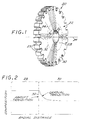
- Figure 1 depicts a gas turbine disk 20 for a gas turbine engine.
- the gas turbine disk 20 may be a turbine disk, a compressor disk, or a fan disk.
- the preferred application is a turbine disk, and the following discussion will focus on the turbine disk.
- the illustrated gas turbine disk 20 has a body 22 that is generally cylindrically symmetric about a central axis 24.
- the gas turbine disk 20 may have a hollow bore 26 at its radial center as illustrated, or it may be solid.
- radial refers to a radial direction 34 perpendicular to the central axis 24, and “axial” refers to an axial direction 36 parallel to the central axis 24.
- the gas turbine disk 20 has slots 25 on its periphery (i.e., rim) into which the attachment portions of turbine blades (not shown) are received.
- the body 22 may be considered as including a radially (relative to the central axis 24) inner segment 28 and a radially outer segment 30 having a composition different from that of the radially inner segment 28.
- a gas turbine disk 20 is termed a "compositionally graded gas turbine disk”.
- the interface 32 may be abrupt, but more preferably is gradual, that is spread over a radial distance to avoid thermal strains, crack-initiation sites, and other discontinuous characteristics associated with an abrupt compositional change.
- Figure 2 schematically illustrates the preferred substantially identical composition at the interface 32 and radially outward gradual-transition composition change of the radially outer segment 30, as compared with an abrupt-transition composition change.
- Either approach may be prepared within the scope of the present approach, but the gradual transition is preferred.
- the radially inner segment 28 has a fixed composition, and the composition of the radially outer segment 30 gradually transitions to the desired composition of the radially outer segment 30.
- the slots 25 are machined into the radially outer segment 30 at the periphery of the gas turbine disk 20.
- Figure 3 depicts in block diagram form a method for making the compositionally graded gas turbine disk 20.
- the method includes first preparing a radially inner segment of a gas turbine disk preform, made of a radially inner-segment material, step 40.
- the radially inner segment of the gas turbine disk preform generally corresponds to the radially inner segment 28 of the final gas turbine disk 20, although it is of a different shape at this stage of the manufacturing process.
- the radially inner segment of the gas turbine disk preform is rotationally symmetric about the central axis 25.
- the radially inner segment of the gas turbine disk preform may be made by any operable approach.
- the radially inner-segment material is made of atomized powder that is consolidated into a billet.
- the billet is then converted by thermomechanical processing, typically including elevated temperature extrusion, into the radially inner segment of the gas turbine disk preform.
- the radially inner segment of the gas turbine disk preform may instead be made by casting and converting or other operable approach.
- the radially inner segment of the gas turbine disk preform is mounted into a suitable apparatus and rotated about the central axis 24, step 42, in a manner similar to the rotation of a workpiece in a lathe.
- the radially inner segment of the gas turbine disk preform serves as a deposition mandrel in the subsequent spray application step.
- the radially outer-segment material is spray applied onto the radially inner segment of the gas turbine disk preform as it rotates about the central axis 24, step 44, to form a radially outer segment of the gas turbine disk preform.
- the radially outer segment of the gas turbine disk preform generally corresponds to the radially outer segment 30 of the final gas turbine disk 30, but it is of a different shape and thickness at this stage of processing.
- the radially outer segment of the gas turbine disk preform is generally cylindrically symmetric about the central axis 42, although there may be relatively small irregularities that are removed in subsequent processing.
- the radially outer-segment material may be applied by any operable approach suitable to the material being applied and deposited.
- operable approaches include spray application by cold spray; high velocity oxyfuel (HVOF); high velocity particle consolidation (HVPC), such as disclosed in US Patent 5,302,414 , whose disclosure is incorporated by reference, and Maurice F. Amateau et al., "High-Velocity Particle Consolidation Technology," IMAST Quarterly 2000, No. 2, pages 3-6 (2000) ; laser additive; or cathodic arc transfer processes.
- the preferred approach is cold spray by a method such as kinetic metallization, which is described, for example, in US Patent 5,795,626 , whose disclosure is incorporated by reference, and Howard Gabel, "Kinetic Metallization Compared with HVOF, Advanced Materials and Processes, pages 47-48 (May 2004 ).
- kinetic metallization a method such as kinetic metallization
- prealloyed powder particles of the radially outer-segment material are sprayed at high velocity and at a relatively low processing temperature onto the surface of the rotating radially inner-segment mandrel.
- This approach is termed “cold spray” because its low processing temperature is typically about 1200-1400°F for the preferred nickel-base superalloy radially outer-segment material.
- This temperature is sufficiently low that the surfaces of the powder particles do not melt or significantly oxidize during the spray processing, producing oxides that would inhibit subsequent compaction and homogenization of the structure.
- the cold spray processing temperatures are also well below key metallurgical temperatures such as the gamma prime solvus of the radially inner segment 28, so that its microstructure is not altered during the application of the radially outer segment 30. This temperature is sufficiently high, however, that the powder particles deform to produce an undensified layer at the deposited surface, which undensified layer gradually thickens as the cold spray continues.
- the cold spray approach is distinct from operable but less preferred hot spray approaches such as HVOF, wherein the sprayed powder particles at least partially melt, leading to potential oxidation of their surfaces during the spray process.
- the spray approach also permits a wide variety of different spatial composition variations in the radially outer segment.
- the composition of the radially outer-segment material may be substantially constant with distance from the central axis 24 and with location along (i.e., parallel to) the central axis 24, the "abrupt transition" material of Figure 2.
- the composition of the radially outer-segment material may instead change and be a function only of distance from the central axis 24, as in the "gradual transition" material of Figure 2, which also features substantially identical compositions at the interface 32.
- the composition of the radially outer-segment material may change and be a function of the distance from the central axis 24 and also the location along the central axis 24. Complex patterns of composition may be utilized if desired, so that, for example, the composition in the region of the slots 25 is different from that of the other regions.
- the gas turbine disk preform may be, and typically is, further processed to produce the compositionally graded gas turbine disk, step 46.
- the further processing optionally includes compacting the gas turbine disk preform, step 48.
- This compacting 48 is normally required because the spray-applied radially outer-segment material may have voids therein, which are closed to achieve a fully dense product in the compaction step 48.
- the compaction 48 may be accomplished by any operable approach.
- the preferred approaches include placing the gas turbine disk preform into a metallic can and then processing by hot isostatic pressing, extrusion, or both.
- the compaction 48 is preferably but optionally followed by further forging, such as upset forging 50, of the gas turbine disk preform.
- the gas turbine disk preform may be, and usually is, heat treated, step 52.
- the heat treatment achieves the desired combination of grain structure and dispersed phase structure within the material.
- the heat treatment 52 is spatially non-uniform.
- the gas turbine disk preform may be heated nonuniformly, as with induction elements or heat lamps, or it may be heated uniformly and locally cooled nonuniformly, as with chill blocks or gas currents positioned to achieve local cooling. A combination of these techniques may be used as desired.
- the production of spatially non-uniform heat treatments is complex, and it is preferable to use a spatially uniform heat treatment.
- the radially inner-segment material is of a first composition, such as a first nickel-base superalloy.
- the radially outer-segment material is of a second composition different from the first composition, such as a second nickel-base superalloy.
- the selection of the compositions is made such that the first composition and the second composition may both be effectively heat treated in a common heat-treatment sequence in which the temperatures are uniform throughout the gas turbine disk, but achieve different final properties of the two compositions due to the different compositions.
- a "common heat-treatment sequence" means that the radially inner segment 28 and the radially outer segment 30 are subjected to the same heat treatment temperature-time profile (within the limitations of thermal diffusion through thick sections).
- the inner-segment material is Rene 104, having a high-temperature solvus at about 2110°F
- the outer-segment material is Rene 88, having a high-temperature solvus at about 2035°F.
- Rene 104 has a nominal composition, in weight percent, of 20.6 percent cobalt, 13.0 percent chromium, 3.4 percent aluminum, 3.70 percent titanium, 2.4 percent tantalum, 0.90 percent niobium, 2.10 percent tungsten, 3.80 percent molybdenum, 0.05 percent carbon, 0.025 percent boron, 0.05 percent zirconium, up to 0.5 percent iron, balance nickel and minor impurity elements.
- Rene' 95 An alternative to Rene 104 is Rene' 95, which has a nominal composition, in weight percent, of about 13 percent chromium, about 8 percent cobalt, about 3.5 percent molybdenum, about 3.5 percent tungsten, about 3.5 percent niobium, about 2.5 percent titanium, about 3.5 percent aluminum, about 0.01 percent boron, about 0.05 percent zirconium, about 0.06 percent carbon, balance nickel and incidental impurities.
- Rene 88 has a nominal composition, in weight percent, of 13 percent cobalt, 16 percent chromium, 4 percent molybdenum, 3.7 percent titanium, 2.1 percent aluminum, 4 percent tungsten, 0.75 percent niobium, 0.02 percent boron, 0.04 percent zirconium, and 0.04 percent carbon, balance nickel and minor impurity elements.
- a spatially uniform isothermal heat treatment in the preferred range of 2050-2080°F results in subsolvus heat treatment of the Rene 104, producing a finer grain size preferred for good low-cycle fatigue performance and good tensile strength at moderate temperatures, and a supersolvus solution heat treatment of the Rene 88, producing a coarser grain size preferred for good creep and high-temperature tensile strength.
- the heat treatment 52 is continued with a controlled quench and a lower-temperature age that produces a distribution of gamma prime precipitates in a gamma matrix of each composition.
- the further processing 46 also typically includes rough and final machining, step 54, to define the general surface shape of the final gas turbine disk 20, and also to form specific features such as the bore 26, where present, and the peripheral axial slots 25.
- Surface finishing and/or coating 56 may also be employed. Examples include working the surface as by shot peening, and applying protective surface coatings such as those known in the art.
- the illustrated steps may be performed in any operable sequence, or there may be an intermixing of the steps.
- Upset forging 50 normally follows compaction 48.
- the heat treat step 52 may occur after forging 50, interspersed with the substeps of the forging operation 50, or after machining 54, interspersed with the substeps of the machining operation 54, or in any other operable sequence. Machining 54 may occur at whatever point of the processing that it is needed.
- the surface finishing 56 normally occurs at or near the end of the further processing 46.
Applications Claiming Priority (1)
| Application Number | Priority Date | Filing Date | Title |
|---|---|---|---|
| US11/130,764 US7967924B2 (en) | 2005-05-17 | 2005-05-17 | Method for making a compositionally graded gas turbine disk |
Publications (2)
| Publication Number | Publication Date |
|---|---|
| EP1724439A2 true EP1724439A2 (fr) | 2006-11-22 |
| EP1724439A3 EP1724439A3 (fr) | 2012-09-19 |
Family
ID=36579940
Family Applications (2)
| Application Number | Title | Priority Date | Filing Date |
|---|---|---|---|
| EP06252478.0A Expired - Fee Related EP1724438B1 (fr) | 2005-05-17 | 2006-05-11 | Procédé pour réaliser un disque de turbine à gaz à composition graduée |
| EP06252482A Withdrawn EP1724439A3 (fr) | 2005-05-17 | 2006-05-11 | Procédé pour réaliser un disque de turbine à gaz ayant un gradient de composition |
Family Applications Before (1)
| Application Number | Title | Priority Date | Filing Date |
|---|---|---|---|
| EP06252478.0A Expired - Fee Related EP1724438B1 (fr) | 2005-05-17 | 2006-05-11 | Procédé pour réaliser un disque de turbine à gaz à composition graduée |
Country Status (2)
| Country | Link |
|---|---|
| US (2) | US7967924B2 (fr) |
| EP (2) | EP1724438B1 (fr) |
Families Citing this family (38)
| Publication number | Priority date | Publication date | Assignee | Title |
|---|---|---|---|---|
| US20070081912A1 (en) * | 2005-10-11 | 2007-04-12 | Honeywell International, Inc. | Method of producing multiple microstructure components |
| WO2007069623A1 (fr) * | 2005-12-13 | 2007-06-21 | Nihon University | Procede et appareil de fabrication de materiau biocompatible a gradient fonctionnel circulaire concentrique |
| US7905016B2 (en) * | 2007-04-10 | 2011-03-15 | Siemens Energy, Inc. | System for forming a gas cooled airfoil for use in a turbine engine |
| US8205332B2 (en) * | 2008-12-08 | 2012-06-26 | Mahle International Gmbh | Method of forming a connecting rod from two dissimiliar materials by providing material blanks of dissimiliar material, joining the material blanks and subsequently forming the connecting rod |
| US8020509B2 (en) * | 2009-01-08 | 2011-09-20 | General Electric Company | Apparatus, systems, and methods involving cold spray coating |
| US20100233504A1 (en) * | 2009-03-13 | 2010-09-16 | Honeywell International Inc. | Method of manufacture of a dual microstructure impeller |
| US8261444B2 (en) * | 2009-10-07 | 2012-09-11 | General Electric Company | Turbine rotor fabrication using cold spraying |
| WO2011057661A1 (fr) * | 2009-11-11 | 2011-05-19 | Siemens Aktiengesellschaft | Composant comportant des zones de ductilité différente et procédé de fabrication d'un composant |
| US9216453B2 (en) * | 2009-11-20 | 2015-12-22 | Honeywell International Inc. | Methods of forming dual microstructure components |
| FR2958194B1 (fr) * | 2010-04-02 | 2012-06-15 | Creusot Forge | Procede et dispositif pour la fabrication d'une virole bi-materiaux, et virole ainsi realisee. |
| IT1399883B1 (it) | 2010-05-18 | 2013-05-09 | Nuova Pignone S R L | Girante incamiciata con materiale funzionale graduato e metodo |
| NO332568B1 (no) * | 2011-01-29 | 2012-11-05 | Tool Tech As | Fremgangsmate for fremstilling av ventilblokker ved pulverstoping |
| RU2455115C1 (ru) * | 2011-02-17 | 2012-07-10 | Открытое акционерное общество "Всероссийский институт легких сплавов" (ОАО "ВИЛС") | Способ получения переменной структуры по сечению порошковой заготовки |
| US9249672B2 (en) * | 2011-09-23 | 2016-02-02 | General Electric Company | Components with cooling channels and methods of manufacture |
| US20130078418A1 (en) * | 2011-09-23 | 2013-03-28 | General Electric Company | Components with cooling channels and methods of manufacture |
| DE102013109116A1 (de) | 2012-08-27 | 2014-03-27 | General Electric Company (N.D.Ges.D. Staates New York) | Bauteil mit Kühlkanälen und Verfahren zur Herstellung |
| US9200521B2 (en) * | 2012-10-30 | 2015-12-01 | General Electric Company | Components with micro cooled coating layer and methods of manufacture |
| AU2013375273B2 (en) * | 2013-01-28 | 2017-08-31 | Raytheon Technologies Corporation | Structured material alloy component fabrication |
| US10710161B2 (en) | 2013-03-11 | 2020-07-14 | Raytheon Technologies Corporation | Turbine disk fabrication with in situ material property variation |
| JP6100037B2 (ja) * | 2013-03-13 | 2017-03-22 | 三菱重工業株式会社 | 蒸気タービン翼製造方法 |
| RU2537335C1 (ru) * | 2013-06-24 | 2015-01-10 | Открытое акционерное общество "Всероссийский институт легких сплавов" (ОАО "ВИЛС") | Способ получения биметаллического диска газотурбинного двигателя |
| RU2536124C1 (ru) * | 2013-08-21 | 2014-12-20 | Открытое акционерное общество "Всероссийский институт легких сплавов" (ОАО "ВИЛС") | Способ получения диска газотурбинного двигателя |
| US9555612B2 (en) * | 2014-02-19 | 2017-01-31 | General Electric Company | Treated component and methods of forming a treated component |
| GB2523583C (en) * | 2014-02-28 | 2019-12-25 | Castings Tech International Limited | Forming a composite component |
| US10072510B2 (en) * | 2014-11-21 | 2018-09-11 | General Electric Company | Variable pitch fan for gas turbine engine and method of assembling the same |
| US9938834B2 (en) * | 2015-04-30 | 2018-04-10 | Honeywell International Inc. | Bladed gas turbine engine rotors having deposited transition rings and methods for the manufacture thereof |
| US10294804B2 (en) | 2015-08-11 | 2019-05-21 | Honeywell International Inc. | Dual alloy gas turbine engine rotors and methods for the manufacture thereof |
| US10036254B2 (en) | 2015-11-12 | 2018-07-31 | Honeywell International Inc. | Dual alloy bladed rotors suitable for usage in gas turbine engines and methods for the manufacture thereof |
| US10563293B2 (en) | 2015-12-07 | 2020-02-18 | Ati Properties Llc | Methods for processing nickel-base alloys |
| RU2676121C2 (ru) * | 2016-12-28 | 2018-12-26 | Открытое акционерное общество "Всероссийский институт легких сплавов" (ОАО "ВИЛС") | Порошковые жаропрочные сплавы для изготовления биметаллических изделий и составной диск, изготовленный из этих сплавов |
| US10376960B2 (en) | 2017-01-18 | 2019-08-13 | United Technologies Corporation | Grain size control in laser based additive manufacturing of metallic articles |
| US10315218B2 (en) * | 2017-07-06 | 2019-06-11 | General Electric Company | Method for repairing turbine component by application of thick cold spray coating |
| EP3441165A1 (fr) * | 2017-08-08 | 2019-02-13 | Siemens Aktiengesellschaft | Améliorations apportées à la compression isostatique à chaud |
| EP3441166A1 (fr) * | 2017-08-08 | 2019-02-13 | Siemens Aktiengesellschaft | Améliorations relatives à des composants fabriqués à partir d'alliages métalliques |
| US11174744B2 (en) | 2018-10-01 | 2021-11-16 | Raytheon Technologies Corporation | Multi-material rotor for attritable engines |
| US11707815B2 (en) * | 2019-07-09 | 2023-07-25 | General Electric Company | Creating 3D mark on protective coating on metal part using mask and metal part so formed |
| US11674435B2 (en) | 2021-06-29 | 2023-06-13 | General Electric Company | Levered counterweight feathering system |
| US11795964B2 (en) | 2021-07-16 | 2023-10-24 | General Electric Company | Levered counterweight feathering system |
Citations (4)
| Publication number | Priority date | Publication date | Assignee | Title |
|---|---|---|---|---|
| GB2027060A (en) * | 1978-08-03 | 1980-02-13 | Howmet Turbine Components | Isostatic hot pressing metallic powder preforms |
| GB2085778A (en) * | 1980-10-06 | 1982-05-06 | Gen Electric | Plasma spray-cast components |
| JPS58124003A (ja) * | 1982-01-20 | 1983-07-23 | Ngk Spark Plug Co Ltd | セラミツクタ−ビンロ−タの製造法 |
| GB2241512A (en) * | 1990-03-02 | 1991-09-04 | Gen Electric | Method of forming dual metal structures |
Family Cites Families (13)
| Publication number | Priority date | Publication date | Assignee | Title |
|---|---|---|---|---|
| US3780418A (en) * | 1972-10-10 | 1973-12-25 | Aluminum Co Of America | Method of fabricating composite multi-metallic billets useful for metal working operations |
| NO150668C (no) * | 1981-08-07 | 1984-11-28 | Jan Mowill | Fremgangsmaate til fremstilling av et monolittisk maskindelemne med partier av forskjellig legeringssammensetning ved pulvermetallurgi |
| US4602952A (en) * | 1985-04-23 | 1986-07-29 | Cameron Iron Works, Inc. | Process for making a composite powder metallurgical billet |
| US4851190A (en) * | 1987-07-27 | 1989-07-25 | Williams International Corporation | Method of making a multi-alloy turbine rotor disk |
| US4900635A (en) * | 1987-07-27 | 1990-02-13 | Williams International Corporation | Multi-alloy turbine rotor disk |
| JPS6447828A (en) * | 1987-08-12 | 1989-02-22 | Agency Ind Science Techn | Turbin disk by super plastic forging of different alloys |
| US5038014A (en) * | 1989-02-08 | 1991-08-06 | General Electric Company | Fabrication of components by layered deposition |
| US5161950A (en) * | 1989-10-04 | 1992-11-10 | General Electric Company | Dual alloy turbine disk |
| DE69016433T2 (de) * | 1990-05-19 | 1995-07-20 | Papyrin Anatolij Nikiforovic | Beschichtungsverfahren und -vorrichtung. |
| US5795626A (en) * | 1995-04-28 | 1998-08-18 | Innovative Technology Inc. | Coating or ablation applicator with a debris recovery attachment |
| US6162552A (en) * | 1998-12-03 | 2000-12-19 | General Electric Company | Rhenium-coated tungsten-based alloy and composite articles and method therefor |
| US6248286B1 (en) * | 1999-12-03 | 2001-06-19 | Ut-Battelle, Llc | Method of making a functionally graded material |
| US6887529B2 (en) * | 2003-04-02 | 2005-05-03 | General Electric Company | Method of applying environmental and bond coatings to turbine flowpath parts |
-
2005
- 2005-05-17 US US11/130,764 patent/US7967924B2/en not_active Expired - Fee Related
- 2005-09-19 US US11/229,823 patent/US7537725B2/en not_active Expired - Fee Related
-
2006
- 2006-05-11 EP EP06252478.0A patent/EP1724438B1/fr not_active Expired - Fee Related
- 2006-05-11 EP EP06252482A patent/EP1724439A3/fr not_active Withdrawn
Patent Citations (4)
| Publication number | Priority date | Publication date | Assignee | Title |
|---|---|---|---|---|
| GB2027060A (en) * | 1978-08-03 | 1980-02-13 | Howmet Turbine Components | Isostatic hot pressing metallic powder preforms |
| GB2085778A (en) * | 1980-10-06 | 1982-05-06 | Gen Electric | Plasma spray-cast components |
| JPS58124003A (ja) * | 1982-01-20 | 1983-07-23 | Ngk Spark Plug Co Ltd | セラミツクタ−ビンロ−タの製造法 |
| GB2241512A (en) * | 1990-03-02 | 1991-09-04 | Gen Electric | Method of forming dual metal structures |
Also Published As
| Publication number | Publication date |
|---|---|
| EP1724438A2 (fr) | 2006-11-22 |
| EP1724439A3 (fr) | 2012-09-19 |
| EP1724438B1 (fr) | 2015-02-25 |
| US20060260126A1 (en) | 2006-11-23 |
| US7967924B2 (en) | 2011-06-28 |
| US20060263231A1 (en) | 2006-11-23 |
| US7537725B2 (en) | 2009-05-26 |
| EP1724438A3 (fr) | 2012-09-19 |
Similar Documents
| Publication | Publication Date | Title |
|---|---|---|
| US7967924B2 (en) | Method for making a compositionally graded gas turbine disk | |
| JP5398123B2 (ja) | ニッケル系合金 | |
| US4479293A (en) | Process for fabricating integrally bladed bimetallic rotors | |
| EP0421229B1 (fr) | Alliage résistant au fluage et à la charge de rupture présentant une bonne résistance aux fendillements par fatigue après un maintien prolongé | |
| US4418124A (en) | Plasma spray-cast components | |
| US6551372B1 (en) | High performance wrought powder metal articles and method of manufacture | |
| US5273708A (en) | Method of making a dual alloy article | |
| JP6165417B2 (ja) | 構成要素及び異なる粒子構造を有する領域を有する構成要素を製造する方法 | |
| US8703045B2 (en) | Method of manufacturing a multiple composition component | |
| US20120148412A1 (en) | Fatigue resistant cast titanium alloy articles | |
| CN104759830B (zh) | 生产性能增强的金属材料的方法 | |
| JP2011080463A (ja) | 冷間溶射を用いたタービンローターの製作 | |
| US5318217A (en) | Method of enhancing bond joint structural integrity of spray cast article | |
| US10737314B2 (en) | Method for producing forged TiAl components | |
| US4447466A (en) | Process for making plasma spray-cast components using segmented mandrels | |
| JPH02255268A (ja) | 超耐熱合金製ディスクの製造方法 | |
| EP1524325B1 (fr) | Procédé pour diminuer les tensions résiduelles des pièces en superalliage à base de nickel après un recuit de mise en solution | |
| EP2230037A1 (fr) | Procédé de fabrication d'une hélice à microstructure double | |
| EP2333244B1 (fr) | Procédés de formation de composants à microstructure double | |
| US6063212A (en) | Heat treated, spray formed superalloy articles and method of making the same | |
| Valitov et al. | The effect of thermomechanical treatment conditions on the structure and properties of the granulated EP741NP nickel alloy | |
| EP1013790B1 (fr) | Procédé de fabrication des objets en superalliage formés par projection et traités thermiquement | |
| US10351940B2 (en) | Method of manufacturing a component from a nickel-based superalloy | |
| CN101187316A (zh) | 耐热性得到提高的可变几何形状涡轮增压器的排气引导器组件 | |
| CA1217073A (fr) | Pieces moulees par projection au plasma |
Legal Events
| Date | Code | Title | Description |
|---|---|---|---|
| PUAI | Public reference made under article 153(3) epc to a published international application that has entered the european phase |
Free format text: ORIGINAL CODE: 0009012 |
|
| AK | Designated contracting states |
Kind code of ref document: A2 Designated state(s): AT BE BG CH CY CZ DE DK EE ES FI FR GB GR HU IE IS IT LI LT LU LV MC NL PL PT RO SE SI SK TR |
|
| AX | Request for extension of the european patent |
Extension state: AL BA HR MK YU |
|
| RAP1 | Party data changed (applicant data changed or rights of an application transferred) |
Owner name: GENERAL ELECTRIC COMPANY |
|
| PUAL | Search report despatched |
Free format text: ORIGINAL CODE: 0009013 |
|
| AK | Designated contracting states |
Kind code of ref document: A3 Designated state(s): AT BE BG CH CY CZ DE DK EE ES FI FR GB GR HU IE IS IT LI LT LU LV MC NL PL PT RO SE SI SK TR |
|
| AX | Request for extension of the european patent |
Extension state: AL BA HR MK YU |
|
| RIC1 | Information provided on ipc code assigned before grant |
Ipc: B22F 3/00 20060101ALI20120815BHEP Ipc: F01D 25/00 20060101ALI20120815BHEP Ipc: B23P 15/00 20060101ALI20120815BHEP Ipc: B22F 7/06 20060101ALI20120815BHEP Ipc: B22F 5/00 20060101ALI20120815BHEP Ipc: B22F 3/12 20060101ALI20120815BHEP Ipc: F01D 5/02 20060101AFI20120815BHEP |
|
| 17P | Request for examination filed |
Effective date: 20130319 |
|
| AKX | Designation fees paid |
Designated state(s): DE FR GB |
|
| GRAP | Despatch of communication of intention to grant a patent |
Free format text: ORIGINAL CODE: EPIDOSNIGR1 |
|
| INTG | Intention to grant announced |
Effective date: 20140314 |
|
| GRAS | Grant fee paid |
Free format text: ORIGINAL CODE: EPIDOSNIGR3 |
|
| STAA | Information on the status of an ep patent application or granted ep patent |
Free format text: STATUS: THE APPLICATION IS DEEMED TO BE WITHDRAWN |
|
| 18D | Application deemed to be withdrawn |
Effective date: 20141202 |