EP1723875A1 - Furniture accessory - Google Patents
Furniture accessory Download PDFInfo
- Publication number
- EP1723875A1 EP1723875A1 EP06001691A EP06001691A EP1723875A1 EP 1723875 A1 EP1723875 A1 EP 1723875A1 EP 06001691 A EP06001691 A EP 06001691A EP 06001691 A EP06001691 A EP 06001691A EP 1723875 A1 EP1723875 A1 EP 1723875A1
- Authority
- EP
- European Patent Office
- Prior art keywords
- frame
- movable frame
- furniture
- accessory
- extraction
- Prior art date
- Legal status (The legal status is an assumption and is not a legal conclusion. Google has not performed a legal analysis and makes no representation as to the accuracy of the status listed.)
- Withdrawn
Links
Images


Classifications
-
- A—HUMAN NECESSITIES
- A47—FURNITURE; DOMESTIC ARTICLES OR APPLIANCES; COFFEE MILLS; SPICE MILLS; SUCTION CLEANERS IN GENERAL
- A47B—TABLES; DESKS; OFFICE FURNITURE; CABINETS; DRAWERS; GENERAL DETAILS OF FURNITURE
- A47B81/00—Cabinets or racks specially adapted for other particular purposes, e.g. for storing guns or skis
- A47B81/002—Corner cabinets; Cabinets designed for being placed in a corner or a niche
Definitions
- the present invention relates to an accessory for furniture in accordance with the preamble of Claim 1. More particularly the invention relates to an accessory intended to support a frontally extracted built-in unit in corner furniture.
- corner furniture is used to indicate not only furniture comprising two sections arranged at right angles with respect to each other, but also two pieces of furniture arranged against two respective different adjacent walls in a corner of a room, as well as furniture having an internal part which is accessible only via a front opening positioned laterally and extending over a distance smaller than the frontal width of the furniture.
- the furniture in question is corner furniture and the frontally extracted built-in unit is arranged near the corner of the furniture and the inside of the angle formed
- problems of interference between the extracted part of the built-in unit and the remaining parts of the said furniture may occur.
- the problems of interference occur between the widest part of the built-in unit, namely its front panel, and the handles projecting from the adjacent front panels, arranged at right angles with each other along the inside of the angle formed by the furniture.
- the problem of interference is greater in furniture having handles which extend over most of the width of the front panel of the built-in unit or where the handles are positioned close to the internal angle defined by the corner furniture.
- corner furniture having two separate built-in units displaceable horizontally so that a first unit is extractable frontally from the furniture and the second unit is connected to said first unit so that it may be moved by the latter into the position previously occupied by it.
- the first built-in unit at the end of the frontal extraction movement may be rotated through about 90° about a vertical axis of rotation positioned laterally at the front end of the furniture, so as to allow easier access to the second built-in unit.
- an extraction system able to overcome partly the abovementioned problems is provided.
- a guide for extraction of the built-in unit which is slightly curved instead of straight along its initial section, namely along the innermost part inside the furniture body, it is possible to impart a first limited rotational movement to the built-in unit during the initial part of its extraction, so as to prevent its front panel from interfering with the handle of the adjacent front panel arranged at right angles with respect thereto.
- the problem underlying the present invention is to devise a furniture accessory which has structural and functional characteristics such as to satisfy the abovementioned requirement, avoiding at the same time the drawbacks mentioned with reference to the prior art.
- the proposed solution forming the basis of the present invention is that of making use of the smaller width of the body of the front unit to be extracted with respect to the width of its panel, so as to obtain a displacement laterally of the said front panel, thus moving the front panel away from the side where problems of interference may arise.
- the front panel may be displaced until it is positioned flush with the side of the body of the built-in unit.
- the abovementioned lateral displacement is performed during the extraction movement of the built-in unit after the latter has been extracted by an amount greater than the thickness of the front panel and before the front panel interferes with the projecting parts of an adjacent front panel arranged at right angles.
- 1 denotes overall an accessory according to the invention intended to be applied to corner furniture 3.
- the furniture 3 consists of a combination of several modules, 3a, 3b and 3c, respectively, which are arranged at right angles with each other so as to define an L.
- This configuration of the furniture is designed to allow positioning thereof in the corner of a room, for example a kitchen.
- the modules 3a and 3b are arranged laterally next to each other along a first side of the L, while the remaining module 3c which defines the second side of the L is positioned so as to have a side thereof arranged next to a front portion of the end of the furniture module 3b.
- the module 3b With particular reference to the module 3b it can be seen that its body defines a compartment 2 having a front aperture 4 which extends over a predefined distance K1 less than the front width K of the module 3b as measured from its side wall 5 (left-hand side wall in Figures 1 and 2).
- the front opening 4 of the module 3b is less than the front width of the said module since the remaining front portion 2 is intended to be covered by the side of the module 3c.
- About half of the compartment 2 (the right-hand half in the figure) is inset with respect to the front opening 4.
- Each of the abovementioned modules 3a, 3b and 3c is closed by a respective front panel 6 (6a, 6b, 6c) with a predefined thickness S able to cover the front opening of the respective module A.
- Each front panel 6 is then fitted with a handle or grip 7 (7a, 7b and 7c, respectively) which allows the front panel 6 to be operated in order to access the internal part of the respective module 3a, 3b and 3c.
- the compartment 2 of the module 3b is intended to receive two respective built-in units 8 and 9 which are positioned next to each other in the direction of the front width K of the module 3b.
- the first built-in unit 8 is positioned in substantial alignment with the front opening 4 of the compartment 2 and has a width Z3 slightly less than the width K2 of the said opening and a depth such that it may be contained entirely within the compartment 2.
- the second built-in unit 9 has dimensions such that it may be housed inside the abovementioned half of the compartment 2 which is inset with respect to the front opening 4 of the compartment 2.
- these units may be of varying types depending on needs, having elements such as drawers, baskets, trolleys and the like.
- the latter is supported by the body of the module 3b so that it may be extracted frontally from the compartment 2 through the abovementioned front opening 4 of predefined width K1.
- the first built-in unit 8 is therefore able to pass in a reversible manner from a retracted position ( Figures 3, 6) into an extracted position ( Figures 1, 8, 10), where the first built-in unit 8 is entirely housed inside the compartment 2 and is extracted frontally from the compartment 2, respectively.
- the accessory 1 comprises:
- the movable frame 11 comprises a front side 11a positioned substantially along the abovementioned front opening 4 of the module 3b, when the movable frame is in the retracted position ( Figure 3). Obviously the dimensions of the movable frame 11 are such as to allow the movement out from the front opening 4 of the compartment 2.
- the first guide means take the form of an extraction guide 12 extending along the wall 5 of the module 3b in a predefined direction of extraction Y-Y, which is horizontal with respect to the ground and is perpendicular with respect to the front wall of the module 3b.
- the guide 12 is formed by two complementary rails, i.e. a fixed rail 12a and movable rail 12b, sliding coupled together in such a way that the movable rail 12b is able to slide with respect to the fixed rail 12a in the direction of extraction Y-Y.
- the movable rail 12b is slidably coupled to the fixed rail 12a with rolling means arranged in between.
- the movable rail 12b is fixed to the movable frame 11, while the fixed rail 12a is fixed to the fixed frame 10 so as to be supported by the latter. More specifically, the fixed rail 12a is fixed to the fixed frame 10 only at its front end point where the fixed rail 12a is hinged with the fixed frame 10 so as to be able to rotate about a vertical axis of rotation Z-Z positioned substantially along the front side of the module 3b next to the wall 5.
- the abovementioned hinged connection of the fixed rail 12a to the fixed frame 10 allows the extraction guide 12 the possibility to rotate about the axis of rotation Z-Z together with the movable frame 11 and the first built-in unit 8.
- the accessory 1 comprises an engaging element 13 integral with the movable frame 11 and able to engage with the fixed frame 10 so as to prevent the abovementioned rotation of the extraction guide 12 about the axis of rotation Z-Z, for as long as the movable frame 11 is in the retracted position or has not yet reached the extracted position.
- the engaging element 13 is disengaged from the fixed frame 10 so as to allow the extraction guide 12 to rotate until it reaches a rotated end-of-travel position ( Figure 2) together with the movable frame 11 and the first built-in unit 8.
- this further rotational movement allows rotation of the first built-in unit 8 about the axis Z-Z through an angle slightly less than 90°, so as to move the first built-in unit 8 away from the front opening 4 of the compartment 2 and facilitate access to the second built-in unit 9.
- the engaging element 13 is fixed to the movable frame 11 in the vicinity of its end remote from the front side 11a so as to achieve a greater stability of the first built-in unit 8 during the frontal extraction movement from the retracted position into the extracted position.
- the second built-in unit 9 is mounted on a support frame 14 which is inserted inside the compartment 2 so as to be able to be displaced laterally from:
- the support frame 14 is operationally associated with the movable frame 11 and if necessary also with the fixed frame 10, by means of an actuating device 15 so that the displacement of the movable frame 11 from the retracted position ( Figure 3) into the extracted position ( Figures 1, 8), and vice versa, produces a corresponding displacement of the support frame 14 from the first position (Figure 1) towards the second position ( Figure 2) and vice versa.
- Said second position ( Figure 2) is reached by the support frame 14 during the rotational movement from the extracted position into the rotated end-of-travel position of the movable frame 11 about the axis Z-Z of rotation.
- the abovementioned actuating device 15 comprises hinged levers, pins, spring means, stop means and other mechanical parts able to interact with each other so as to produce the movement of the support frame from the first position into the second position as a result of a displacement of the movable frame from the retracted position into the extracted position and the rotated end-of-travel position.
- This device has characteristic features which are known per se to a person skilled in the art and is not described below in detail for the sake of brevity of the description.
- the actuating device may be designed in various ways known per se, for example as described in the document US 3863279 or in the document EP 0820244 A .
- the displacement of the support frame 14 and the second built-in unit 9 may be performed manually provided that it has wheels or is mounted on a rail extending parallel to the front end of the module 3b.
- the accessory 1 comprises:
- the initial position is that where the front frame is situated when the movable frame 11 is in the retracted position.
- the front panel 6b is perfectly aligned with the front opening 4 of the compartment 2 of the module 3b so as to ensure closing thereof.
- the offset position is that which the front frame 16 is made to assume so as to obtain a corresponding displacement (to the left with reference to Figure 1) in the position of the front panel 6b with respect to the initial position in order to prevent said panel interfering with the handle 7c of the front panel 6c.
- the displacement of the front frame 16 from the initial position into the laterally offset position occurs in the form of a horizontal translatory movement in a transverse direction X-X parallel to the front side of the module 3b.
- the second guide means are in the form of a sliding guide 21 extending in the transverse direction X-X and comprising a fixed rail 21a and a movable rail 21b slidably coupled together so that the movable rail 21b is able to slide with respect to the fixed rail 21a in the transverse direction X-X.
- the movable rail 21b is slidably coupled to the fixed rail 21a with the arrangement of rolling means in between.
- the fixed rail 21a is associated with the front side of the movable frame, while the movable rail 21b is associated with the front frame 16.
- the accessory 1 comprises stop means (not shown) for limiting the end-of-travel positions of the extraction guides 12 and the sliding guides 21.
- the actuating means 18 act so as to cause the displacement of the front frame 16 from the initial position into the offset position only after the front panel 6b of the module 3b has performed an extraction movement towards the outside of the compartment 2 at least equal to the thickness S of the said front panel.
- the displacement of the front frame from the initial position into the laterally offset position may comprise a roto-translatory movement.
- the second guide means comprise at least two spaced arms having a first end fixed to the front frame so as to support it and a second end connected to the movable frame so as to be able to rotate with respect thereto about a vertical axis of rotation.
- the actuating means 18 comprise a cam system comprising a cam track 19 associated with the fixed frame 10 and a cam follower integral with the front frame 16.
- the cam follower and the cam may be associated in a dual manner with the front frame and, respectively, with the fixed frame 10 or with the body of the module 3b.
- the cam track 19 is integral with the fixed rail 12 of the extraction guide 12. This allows the cam track 19 the possibility of rotating together with the sliding guide 12 as far as the rotated end-of-travel position, without the cam follower 20 ever having to be disengaged from the cam track 19.
- the cam system is of the bilateral desmodromic type, namely it forms a fully constrained system able to guide the cam follower 20 along the cam track 19 precisely during sliding of the movable frame 11 from the retracted position into the extracted position and vice versa.
- the cam track is defined by a groove formed in a plate so as to define an S-shaped track extending mainly in the direction Y-Y.
- the end 19a of the cam track 19 closest to the front side 11a of the movable frame 11 is offset laterally in the transverse direction X-X with respect to the other end 19b by an amount equal to the offset displacement which is to be imparted to the front frame 11.
- the first section of the cam track 19 from its end 19b is substantially straight and arranged in the direction Y-Y so as to prevent that the offset displacement of the front panel 6b occurs at the start of the extraction movement of the built-in unit 8 from the compartment 2.
- the cam track 19 defines solely a unilateral constraint for the cam follower 20.
- the abovementioned actuating means comprise spring means (not shown) acting with a predefined resilient load on the front frame 16 so as to keep the cam follower constantly in contact with the cam track 19 during sliding of the movable frame from the retracted position into the extracted position and vice versa.
- the furniture accessory according to the present invention is able to satisfy the abovementioned requirement and overcome at the same time the drawbacks referred to in the introductory part of the present description with reference to the prior art.
- the accessory 1 is able to impart to the front panel of the built-in unit during its extraction, it is possible to avoid interference between said front panel and the handles on other front panels of the furniture.
- Another advantage of the accessory according to the present invention consists in the possibility of adjusting the lateral displacement which the front panel of the extractable built-in unit must perform depending on the specific requirements.
- Another further advantage of the accessory according to the present invention consists in the possibility of adaptation to extraction systems of built-in units formed differently from each other.
Landscapes
- Drawers Of Furniture (AREA)
Abstract
An accessory (1), intended to support a frontally extracted built-in unit inside corner furniture comprises a fixed frame (10) able to be associated with an internal wall of the furniture and a movable frame (11) able to support the built-in unit. The movable frame (11) is associated with the fixed frame (10) by the arrangement, in between, of guide means (12) able to allow an extracting sliding movement of the movable frame (11) with respect to the fixed frame (12). Advantageously the accessory comprises a front frame (16) associated with said movable frame (11), along the front side of the furniture, by the arrangement, in between, of a sliding guide (21) extending in a direction transverse to the direction of extraction, so as to allow the front frame (16) to be displaced with respect to the movable frame (11) from a predefined initial position into a position laterally offset with respect to the vertical. The accessory also comprises means (18) for guiding the displacement of the front frame (16) towards the abovementioned laterally offset position during the extraction movement of the movable frame (11).
Description
- The present invention relates to an accessory for furniture in accordance with the preamble of
Claim 1. More particularly the invention relates to an accessory intended to support a frontally extracted built-in unit in corner furniture. - In connection with the present description the term "corner furniture" is used to indicate not only furniture comprising two sections arranged at right angles with respect to each other, but also two pieces of furniture arranged against two respective different adjacent walls in a corner of a room, as well as furniture having an internal part which is accessible only via a front opening positioned laterally and extending over a distance smaller than the frontal width of the furniture.
- In the context of furniture, in particular kitchen furniture, it is very common to use built-in units which can be extracted frontally, such as sets of drawers, baskets and the like. The extraction operation is performed by gripping special handles provided on the front panel of the built-in unit.
- In the case where the furniture in question is corner furniture and the frontally extracted built-in unit is arranged near the corner of the furniture and the inside of the angle formed, it is clear that, during the extraction movement of the built-in unit, problems of interference between the extracted part of the built-in unit and the remaining parts of the said furniture may occur. In particular, the problems of interference occur between the widest part of the built-in unit, namely its front panel, and the handles projecting from the adjacent front panels, arranged at right angles with each other along the inside of the angle formed by the furniture.
- In this connection it should be mentioned that only in a minority of cases are the front panels of the built-in units seated inside special recesses so as to be substantially flush with the front surface of the built-in unit, since in most cases the handles used project from the front panels of the built-in units by as much as three centimetres or more.
- The problem of interference is greater in furniture having handles which extend over most of the width of the front panel of the built-in unit or where the handles are positioned close to the internal angle defined by the corner furniture.
- The need to solve the problems arising from the abovementioned interference is particularly pressing since very often corner furniture is used when furnishing an environment such as a kitchen.
- Thus, for example, it is known to use corner furniture having two separate built-in units displaceable horizontally so that a first unit is extractable frontally from the furniture and the second unit is connected to said first unit so that it may be moved by the latter into the position previously occupied by it. Generally, the first built-in unit at the end of the frontal extraction movement may be rotated through about 90° about a vertical axis of rotation positioned laterally at the front end of the furniture, so as to allow easier access to the second built-in unit.
- An example of such corner furniture and associated accessories for moving the two built-in units can be found in the documents
US 3863279 andEP 0820244 A . - With regard to the abovementioned documents it is pointed out that in them the problems arising from the abovementioned interference remain unsolved. In fact, in both the abovementioned documents, the side of the furniture arranged at right angles with respect to the front panel of the extractable built-in unit has no handles or other parts projecting in the vicinity of the corner of the furniture.
- According to the teaching of the document
EP 1050246 A2 , an extraction system able to overcome partly the abovementioned problems is provided. In fact, owing to a guide for extraction of the built-in unit which is slightly curved instead of straight along its initial section, namely along the innermost part inside the furniture body, it is possible to impart a first limited rotational movement to the built-in unit during the initial part of its extraction, so as to prevent its front panel from interfering with the handle of the adjacent front panel arranged at right angles with respect thereto. - It should be pointed out that this solution is only reasonably satisfactory in that, considering:
- the greater constructional difficulties,
- the greater volume of the extraction actuating device,
- the greater difficulty in obtaining a smooth extraction movement of the built-in unit, and
- the higher production costs,
- The problem underlying the present invention is to devise a furniture accessory which has structural and functional characteristics such as to satisfy the abovementioned requirement, avoiding at the same time the drawbacks mentioned with reference to the prior art.
- This problem is solved by a furniture accessory in accordance with the characteristic features of
Claim 1. - The proposed solution forming the basis of the present invention is that of making use of the smaller width of the body of the front unit to be extracted with respect to the width of its panel, so as to obtain a displacement laterally of the said front panel, thus moving the front panel away from the side where problems of interference may arise. Advantageously the front panel may be displaced until it is positioned flush with the side of the body of the built-in unit. The abovementioned lateral displacement is performed during the extraction movement of the built-in unit after the latter has been extracted by an amount greater than the thickness of the front panel and before the front panel interferes with the projecting parts of an adjacent front panel arranged at right angles. Further characteristic features and advantages of the furniture accessory according to the present invention will emerge from the description below of some preferred examples of embodiment thereof, provided by way of a non-limiting example, with reference to the accompanying figures in which:
- Figure 1 shows a schematic plan view of a piece of furniture comprising the accessory according to the invention in a configuration in which the first built-in unit is in a position extracted from the furniture;
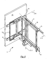
- Figure 2 shows a plan view of the furniture according to Figure 1 when the first built-in unit is in a rotated end-of-travel position;
- Figure 3 shows a view of a detail of Figure 1 with the first built-in unit in the retracted position;
- Figures 4 and 5 show the detail of Figure 3 with the first built-in unit during two subsequent stages of extraction from the furniture compartment;
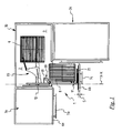
- Figure 6 shows a simplified perspective view of the accessory according to Figure 1 in the retracted configuration;
- Figure 7 shows an enlarged detail of Figure 6;
- Figure 8 shows a simplified perspective view of the accessory according to Figure 1 in the extracted configuration;
- Figure 9 shows an enlarged detail of Figure 8; and
- Figure 10 shows a simplified perspective view of the accessory according to the invention in the extracted configuration and in accordance with a different embodiment thereof.
- With reference to the accompanying figures, 1 denotes overall an accessory according to the invention intended to be applied to corner furniture 3.
- In the example the furniture 3 consists of a combination of several modules, 3a, 3b and 3c, respectively, which are arranged at right angles with each other so as to define an L. This configuration of the furniture is designed to allow positioning thereof in the corner of a room, for example a kitchen. The
modules remaining module 3c which defines the second side of the L is positioned so as to have a side thereof arranged next to a front portion of the end of thefurniture module 3b. - With particular reference to the
module 3b it can be seen that its body defines acompartment 2 having a front aperture 4 which extends over a predefined distance K1 less than the front width K of themodule 3b as measured from its side wall 5 (left-hand side wall in Figures 1 and 2). As regards that described above, the front opening 4 of themodule 3b is less than the front width of the said module since theremaining front portion 2 is intended to be covered by the side of themodule 3c. About half of the compartment 2 (the right-hand half in the figure) is inset with respect to the front opening 4. - Each of the
abovementioned modules respective module - The
compartment 2 of themodule 3b is intended to receive two respective built-inunits module 3b. - The first built-in
unit 8 is positioned in substantial alignment with the front opening 4 of thecompartment 2 and has a width Z3 slightly less than the width K2 of the said opening and a depth such that it may be contained entirely within thecompartment 2. - The second built-in
unit 9 has dimensions such that it may be housed inside the abovementioned half of thecompartment 2 which is inset with respect to the front opening 4 of thecompartment 2. - With reference to the built-in
units - In order to allow easy access to the
first inset unit 8, the latter is supported by the body of themodule 3b so that it may be extracted frontally from thecompartment 2 through the abovementioned front opening 4 of predefined width K1. - The first built-in
unit 8 is therefore able to pass in a reversible manner from a retracted position (Figures 3, 6) into an extracted position (Figures 1, 8, 10), where the first built-inunit 8 is entirely housed inside thecompartment 2 and is extracted frontally from thecompartment 2, respectively. - In order to allow the movement of the first built-in
unit 8, theaccessory 1 according to the invention comprises: - a
fixed frame 10 fixed to theinternal side wall 5 of themodule 3b, - a
movable frame 11 able to support the abovementioned first built-inunit 8, and - first guide means arranged between the
fixed frame 10 and themovable frame 11 so as to allow themovable frame 11 to move with respect to thefixed frame 10 such that the first built-in unit is moved between the retracted position (Figure 3) and the extracted position (Figure 1). - The
movable frame 11 comprises afront side 11a positioned substantially along the abovementioned front opening 4 of themodule 3b, when the movable frame is in the retracted position (Figure 3). Obviously the dimensions of themovable frame 11 are such as to allow the movement out from the front opening 4 of thecompartment 2. - In the example, the first guide means take the form of an
extraction guide 12 extending along thewall 5 of themodule 3b in a predefined direction of extraction Y-Y, which is horizontal with respect to the ground and is perpendicular with respect to the front wall of themodule 3b. Theguide 12 is formed by two complementary rails, i.e. afixed rail 12a andmovable rail 12b, sliding coupled together in such a way that themovable rail 12b is able to slide with respect to the fixedrail 12a in the direction of extraction Y-Y. Preferably themovable rail 12b is slidably coupled to the fixedrail 12a with rolling means arranged in between. - The
movable rail 12b is fixed to themovable frame 11, while thefixed rail 12a is fixed to thefixed frame 10 so as to be supported by the latter. More specifically, thefixed rail 12a is fixed to thefixed frame 10 only at its front end point where thefixed rail 12a is hinged with thefixed frame 10 so as to be able to rotate about a vertical axis of rotation Z-Z positioned substantially along the front side of themodule 3b next to thewall 5. - The abovementioned hinged connection of the
fixed rail 12a to thefixed frame 10 allows theextraction guide 12 the possibility to rotate about the axis of rotation Z-Z together with themovable frame 11 and the first built-inunit 8. - Furthermore, the
accessory 1 comprises an engagingelement 13 integral with themovable frame 11 and able to engage with the fixedframe 10 so as to prevent the abovementioned rotation of theextraction guide 12 about the axis of rotation Z-Z, for as long as themovable frame 11 is in the retracted position or has not yet reached the extracted position. Differently, when themovable frame 11 reaches the extracted end-of-travel position, the engagingelement 13 is disengaged from the fixedframe 10 so as to allow theextraction guide 12 to rotate until it reaches a rotated end-of-travel position (Figure 2) together with themovable frame 11 and the first built-inunit 8. - At the end of the frontal extraction movement of the
movable frame 11 from thecompartment 2, this further rotational movement allows rotation of the first built-inunit 8 about the axis Z-Z through an angle slightly less than 90°, so as to move the first built-inunit 8 away from the front opening 4 of thecompartment 2 and facilitate access to the second built-inunit 9. - Advantageously, the engaging
element 13 is fixed to themovable frame 11 in the vicinity of its end remote from thefront side 11a so as to achieve a greater stability of the first built-inunit 8 during the frontal extraction movement from the retracted position into the extracted position. - According to a preferred embodiment, the second built-in
unit 9 is mounted on asupport frame 14 which is inserted inside thecompartment 2 so as to be able to be displaced laterally from: - a first position (Figure 1) where the second built-in
unit 9 is situated adjacent to said first built-inunit 8, when saidmovable frame 11 is in the retracted position, - and a second position (Figure 2) where the second built-in
unit 9 occupies at least partly the space occupied by said first built-inunit 8 when saidmovable frame 11 is in the retracted position. - When the second built-in
unit 9 is in the abovementioned second position (Figure 2), it is positioned substantially opposite the front opening 4 of thecompartment 2 of themodule 3b. - Preferably, the
support frame 14 is operationally associated with themovable frame 11 and if necessary also with the fixedframe 10, by means of anactuating device 15 so that the displacement of themovable frame 11 from the retracted position (Figure 3) into the extracted position (Figures 1, 8), and vice versa, produces a corresponding displacement of thesupport frame 14 from the first position (Figure 1) towards the second position (Figure 2) and vice versa. - Said second position (Figure 2) is reached by the
support frame 14 during the rotational movement from the extracted position into the rotated end-of-travel position of themovable frame 11 about the axis Z-Z of rotation. - The
abovementioned actuating device 15 comprises hinged levers, pins, spring means, stop means and other mechanical parts able to interact with each other so as to produce the movement of the support frame from the first position into the second position as a result of a displacement of the movable frame from the retracted position into the extracted position and the rotated end-of-travel position. This device has characteristic features which are known per se to a person skilled in the art and is not described below in detail for the sake of brevity of the description. Moreover, the actuating device may be designed in various ways known per se, for example as described in the documentUS 3863279 or in the documentEP 0820244 A . The displacement of thesupport frame 14 and the second built-inunit 9 may be performed manually provided that it has wheels or is mounted on a rail extending parallel to the front end of themodule 3b. - In the light of that described above it is clear that by operating the
handle 7b of thefront panel 6b the first built-inunit 8 may be easily extracted from thecompartment 2. However, during this extraction, thefront panel 6b would interfere with thehandle 7c mounted on thepanel 6c of themodule 3c. - Advantageously the abovementioned interference is avoided owing to the fact that the
accessory 1 comprises: - a
front frame 16 which supports thefront panel 6b and is associated with themovable frame 11 at itsfront end 11a by the arrangement, in between, of second guide means able to allow thefront frame 16 to be displaced with respect to themovable frame 11 from a predefined initial position (Figures 1 and 4) into a position laterally offset (Figure 5) with respect to the vertical, and - actuating means 18 suitable for precisely controlling the displacement of the
front frame 16 from the initial position into the offset position during sliding of themovable frame 11 with respect to the fixedframe 10 from the retracted position into the extracted position and for controlling the displacement of thefront frame 16 from the offset position into the initial position during sliding of themovable frame 11 with respect to the fixedframe 10 from the extracted position into the retracted position. - With reference to the abovementioned initial and offset positions it should be pointed out that the initial position is that where the front frame is situated when the
movable frame 11 is in the retracted position. When thefront frame 16 is in the initial position, thefront panel 6b is perfectly aligned with the front opening 4 of thecompartment 2 of themodule 3b so as to ensure closing thereof. - The offset position is that which the
front frame 16 is made to assume so as to obtain a corresponding displacement (to the left with reference to Figure 1) in the position of thefront panel 6b with respect to the initial position in order to prevent said panel interfering with thehandle 7c of thefront panel 6c. - In a preferred embodiment, the displacement of the
front frame 16 from the initial position into the laterally offset position occurs in the form of a horizontal translatory movement in a transverse direction X-X parallel to the front side of themodule 3b. In this case the second guide means are in the form of a slidingguide 21 extending in the transverse direction X-X and comprising a fixedrail 21a and amovable rail 21b slidably coupled together so that themovable rail 21b is able to slide with respect to the fixedrail 21a in the transverse direction X-X. Preferably, themovable rail 21b is slidably coupled to the fixedrail 21a with the arrangement of rolling means in between. - The fixed
rail 21a is associated with the front side of the movable frame, while themovable rail 21b is associated with thefront frame 16. - The
accessory 1 comprises stop means (not shown) for limiting the end-of-travel positions of the extraction guides 12 and the sliding guides 21. - Preferably, the actuating means 18 act so as to cause the displacement of the
front frame 16 from the initial position into the offset position only after thefront panel 6b of themodule 3b has performed an extraction movement towards the outside of thecompartment 2 at least equal to the thickness S of the said front panel. - As an alternative to that described above, the displacement of the front frame from the initial position into the laterally offset position may comprise a roto-translatory movement. In this case, according to a preferred embodiment, the second guide means comprise at least two spaced arms having a first end fixed to the front frame so as to support it and a second end connected to the movable frame so as to be able to rotate with respect thereto about a vertical axis of rotation.
- In accordance with a preferred embodiment the actuating means 18 comprise a cam system comprising a
cam track 19 associated with the fixedframe 10 and a cam follower integral with thefront frame 16. Alternatively, the cam follower and the cam may be associated in a dual manner with the front frame and, respectively, with the fixedframe 10 or with the body of themodule 3b. - According to a preferred embodiment, the
cam track 19 is integral with the fixedrail 12 of theextraction guide 12. This allows thecam track 19 the possibility of rotating together with the slidingguide 12 as far as the rotated end-of-travel position, without thecam follower 20 ever having to be disengaged from thecam track 19. - With reference to the embodiment shown in Figures 1 to 9, the cam system is of the bilateral desmodromic type, namely it forms a fully constrained system able to guide the
cam follower 20 along thecam track 19 precisely during sliding of themovable frame 11 from the retracted position into the extracted position and vice versa. In the example, the cam track is defined by a groove formed in a plate so as to define an S-shaped track extending mainly in the direction Y-Y. As can be seen from the figures, theend 19a of thecam track 19 closest to thefront side 11a of themovable frame 11 is offset laterally in the transverse direction X-X with respect to theother end 19b by an amount equal to the offset displacement which is to be imparted to thefront frame 11. - The first section of the
cam track 19 from itsend 19b is substantially straight and arranged in the direction Y-Y so as to prevent that the offset displacement of thefront panel 6b occurs at the start of the extraction movement of the built-inunit 8 from thecompartment 2. - In accordance with the embodiment of Figure 10, the
cam track 19 defines solely a unilateral constraint for thecam follower 20. In this case, the abovementioned actuating means comprise spring means (not shown) acting with a predefined resilient load on thefront frame 16 so as to keep the cam follower constantly in contact with thecam track 19 during sliding of the movable frame from the retracted position into the extracted position and vice versa. - As can be understood from the above description, the furniture accessory according to the present invention is able to satisfy the abovementioned requirement and overcome at the same time the drawbacks referred to in the introductory part of the present description with reference to the prior art. In fact, owing to the lateral displacement which the
accessory 1 is able to impart to the front panel of the built-in unit during its extraction, it is possible to avoid interference between said front panel and the handles on other front panels of the furniture. - Another advantage of the accessory according to the present invention consists in the possibility of adjusting the lateral displacement which the front panel of the extractable built-in unit must perform depending on the specific requirements.
- Another further advantage of the accessory according to the present invention consists in the possibility of adaptation to extraction systems of built-in units formed differently from each other.
- Obviously, a person skilled in the art, in order to satisfy contingent and specific requirements, may make numerous modifications and variations to the accessory described above, all of these, however, being contained within the scope of protection of the invention as defined by the following claims.
Claims (14)
- Accessory for furniture (3,3a,3b,3c), in particular for corner furniture, having a body inside which a first frontally extracted built-in unit (8) is housed, said accessory (1) comprising:- a fixed frame (10) able to be associated with an internal wall (5) of the body of the furniture (3b),- a movable frame (11) able to support said first frontally extracted built-in unit (8) and having a front side (11a) positioned substantially on the front side of the furniture from which extraction of said first built-in unit (8) is performed,- said movable frame (11) being associated with said fixed frame (10) by the arrangement, in between, of first guide means (12) able to allow a sliding movement in a predefined direction of extraction (Y-Y) of said movable frame (11) with respect to said fixed frame (10) between a retracted position and an extracted position,characterized in that it comprises:- a front frame (16) associated with said movable frame (11) along said front side (11a) by the arrangement, in between, of second guide means (21) able to allow said front frame (16) to be displaced with respect to said movable frame (11) from a predefined initial position into a position laterally offset with respect to the vertical, said front frame (16) being able to support a front panel (6b) of said furniture (3b), and- actuating means (18) for determining the displacement of said front frame (16) from the initial position into the offset position during sliding of the movable frame (11) with respect to the fixed frame (10) from the retracted position into the extracted position and for controlling the displacement of said front frame (16) from the offset position into the initial position during sliding of the movable frame (11) with respect to the fixed frame (10) from the extracted position into the retracted position.
- Accessory according to Claim 1, in which the displacement from the initial position into the laterally offset position of said front frame (16) with respect to the movable frame (11) comprises a translatory movement.
- Accessory according to Claim 1 or 2, in which said second guide means (21) comprise:- a sliding guide (21) extending in a direction (X-X) transverse to said predefined extraction direction (Y-Y), said sliding guide comprising a first rail (21b) and a second rail (21a) integral with said movable frame (11) and said front frame (16), respectively, and- stop means able to define the end-of-travel positions of the sliding movement between said rails (21a,21b).
- Accessory according to Claim 1 or 2, in which the displacement from the initial position into the laterally offset position of said front frame with respect to the movable frame is a roto-translatory movement.
- Accessory according to Claim 4, in which said second guide means comprise:- at least two spaced arms, said arms having a first end fixed to said front frame and a second end connected to said movable frame so as to be able to rotate about a vertical axis of rotation, and- stop means able to limit the amplitude of the abovementioned rotation of at least one of said arms.
- Accessory according to any one of Claims 1 to 5, in which said actuating means (18) allow the displacement of said front frame (16) from the initial position into the offset position after said front panel (6b) of the furniture has performed an extraction movement towards the outside of the furniture (3b) greater than the thickness (S) of the front panel.
- Accessory according to any one of Claims 1 to 6, in which said actuating means (18) comprise a cam system comprising a cam track (19) associated with a first frame between said front frame (16) and said fixed frame (10) and a cam follower (20) integral with a second frame between said front frame (16) and said fixed frame (10).
- Accessory according to Claim 7, in which said cam track (19) defines a unilateral constraint and said actuating means (18) comprise spring means able to keep said cam follower (20) in pressing contact with said cam track (19) during sliding of the movable frame (11) from the retracted position into the extracted position and vice versa.
- Accessory according to Claim 7, in which said cam system is of the bilateral desmodromic type able to guide said cam follower (20) along said cam track (19) during sliding of the movable frame (11) from the retracted position into the extracted position and vice versa.
- Accessory according to any one of Claims 1 to 9, in which said first guide means (12) comprise:- an extraction guide (12) extending along said predefined direction of extraction (Y-Y) and comprising a first part (12b) and a second part (12a) coupled in sliding engagement with each other, said first part (12b) being supported by said movable frame (11) and said second part (121a) being hinged with said fixed frame (10) so as to be able to rotate about a vertical axis of rotation (Z-Z) positioned substantially along the front side of the furniture,- an engaging element (13) integral with said movable frame (11) is able to engage with said fixed frame (10) so as to prevent the rotation of said extraction guide (12) about said axis of rotation (Z-Z), while said movable frame (11) is in a retracted position and until said extracted position is reached, upon reaching said extracted position said engaging element (13) being disengaged from said fixed frame (10) so as to allow the extraction guide (12) to rotate about said vertical axis (Z-Z) together with said movable frame (11) and the first built-in unit (8), assuming a rotated end-of-travel position.
- Accessory (1) according to Claim 10, in which said engaging element (13) is fixed to said movable frame (11) in the vicinity of an end remote from said front side (11a).
- Accessory (1) according to Claim 10 or 11, in which said actuating means (18) comprise a cam system comprising a cam track (19) fixed to either one of said front frame (16) and said second part (12a) of the extraction guide (12) and a cam follower (20) integral with the other one of said front frame (16) and said second part (12a) of the extraction guide (12).
- Accessory (1) according to any one of Claims 1 or 12, comprising a support frame (14) which is able to support a second built-in unit (9) and is supported inside said body so as to be able to be displaced between a first position where it is situated next to said movable frame (11) when said movable frame (11) is positioned in said retracted position, and a second position where it occupies substantially the space occupied by said movable frame (11) when said movable frame (11) is positioned in said retracted position, said support frame (14) being operationally associated with said movable frame (11) so that the displacement of said movable frame (11) from the retracted position into the extracted position, and vice versa, produces a substantial displacement of said support frame (14) from the first position towards said second position and vice versa.
- Accessory (1) according to Claim 13, in which said support frame (14) reaches said second position during the rotating movement, from the extracted position into said rotated end-of-travel position, of said movable frame (11) about said vertical axis of rotation (Z-Z).
Applications Claiming Priority (1)
| Application Number | Priority Date | Filing Date | Title |
|---|---|---|---|
| ITMI20050786 ITMI20050786A1 (en) | 2005-04-29 | 2005-04-29 | ACCESSORY FOR A MOBILE |
Publications (1)
| Publication Number | Publication Date |
|---|---|
| EP1723875A1 true EP1723875A1 (en) | 2006-11-22 |
Family
ID=36498692
Family Applications (1)
| Application Number | Title | Priority Date | Filing Date |
|---|---|---|---|
| EP06001691A Withdrawn EP1723875A1 (en) | 2005-04-29 | 2006-01-27 | Furniture accessory |
Country Status (2)
| Country | Link |
|---|---|
| EP (1) | EP1723875A1 (en) |
| IT (1) | ITMI20050786A1 (en) |
Cited By (4)
| Publication number | Priority date | Publication date | Assignee | Title |
|---|---|---|---|---|
| EP1925237A2 (en) | 2006-11-27 | 2008-05-28 | Hetal-Werke Franz Hettich GmbH & Co. KG | Fitting for a corner cupboard and corner cupboard |
| WO2008116577A1 (en) * | 2007-03-24 | 2008-10-02 | Vauth-Sagel Holding Gmbh & Co. Kg | Extension brace for a cabinet with an angled front |
| ITVR20080085A1 (en) * | 2008-07-30 | 2010-01-31 | Vibo S P A | DEVICE FOR HANDLING AND SUPPORTING FURNITURE ELEMENTS |
| US20220211174A1 (en) * | 2019-05-09 | 2022-07-07 | Jasbir Singh | Access mechanism for an inaccessible interior of a cabinet |
Citations (5)
| Publication number | Priority date | Publication date | Assignee | Title |
|---|---|---|---|---|
| US3863279A (en) * | 1972-10-24 | 1975-02-04 | Oppliger Ulrich | Piece of furniture for a right-angled corner of a room |
| EP0797942A2 (en) * | 1996-03-29 | 1997-10-01 | Compagnucci - S.P.A. | Modular basket-holding framework for left and right-handed corner cabinets |
| EP0820244A1 (en) * | 1995-04-13 | 1998-01-28 | Vauth-Sagel GmbH & Co. Grundstücksverwaltung | Corner-cupboard for setting up in a room corner |
| EP1050246A2 (en) | 1999-05-05 | 2000-11-08 | Peka-Metall Ag | Cupboard |
| DE202004011748U1 (en) * | 2004-07-27 | 2004-10-14 | Julius Blum Gmbh | drawer |
-
2005
- 2005-04-29 IT ITMI20050786 patent/ITMI20050786A1/en unknown
-
2006
- 2006-01-27 EP EP06001691A patent/EP1723875A1/en not_active Withdrawn
Patent Citations (5)
| Publication number | Priority date | Publication date | Assignee | Title |
|---|---|---|---|---|
| US3863279A (en) * | 1972-10-24 | 1975-02-04 | Oppliger Ulrich | Piece of furniture for a right-angled corner of a room |
| EP0820244A1 (en) * | 1995-04-13 | 1998-01-28 | Vauth-Sagel GmbH & Co. Grundstücksverwaltung | Corner-cupboard for setting up in a room corner |
| EP0797942A2 (en) * | 1996-03-29 | 1997-10-01 | Compagnucci - S.P.A. | Modular basket-holding framework for left and right-handed corner cabinets |
| EP1050246A2 (en) | 1999-05-05 | 2000-11-08 | Peka-Metall Ag | Cupboard |
| DE202004011748U1 (en) * | 2004-07-27 | 2004-10-14 | Julius Blum Gmbh | drawer |
Cited By (6)
| Publication number | Priority date | Publication date | Assignee | Title |
|---|---|---|---|---|
| EP1925237A2 (en) | 2006-11-27 | 2008-05-28 | Hetal-Werke Franz Hettich GmbH & Co. KG | Fitting for a corner cupboard and corner cupboard |
| EP1925237A3 (en) * | 2006-11-27 | 2010-12-29 | Hetal-Werke Franz Hettich GmbH & Co. KG | Fitting for a corner cupboard and corner cupboard |
| WO2008116577A1 (en) * | 2007-03-24 | 2008-10-02 | Vauth-Sagel Holding Gmbh & Co. Kg | Extension brace for a cabinet with an angled front |
| ITVR20080085A1 (en) * | 2008-07-30 | 2010-01-31 | Vibo S P A | DEVICE FOR HANDLING AND SUPPORTING FURNITURE ELEMENTS |
| US20220211174A1 (en) * | 2019-05-09 | 2022-07-07 | Jasbir Singh | Access mechanism for an inaccessible interior of a cabinet |
| US12102223B2 (en) * | 2019-05-09 | 2024-10-01 | Jasbir Singh | Access mechanism for an inaccessible interior of a cabinet |
Also Published As
| Publication number | Publication date |
|---|---|
| ITMI20050786A1 (en) | 2006-10-30 |
Similar Documents
| Publication | Publication Date | Title |
|---|---|---|
| JP5390190B2 (en) | Furniture item having first and second furniture parts | |
| CN101208028B (en) | Improved frame to support pull-out and rotating racks for cabinets | |
| JP5762438B2 (en) | Traveling device having guide rails for sliding doors | |
| CN110191994B (en) | Guiding system for a door leaf | |
| US10000962B2 (en) | Guiding device for a sliding door | |
| CN103002775A (en) | A hooking device for hooking a drawer to a longitudinal guide | |
| EP2112436B1 (en) | Mechanism for extracting a tray from a domestic oven | |
| EP1723875A1 (en) | Furniture accessory | |
| AU2006316672A1 (en) | Drawer | |
| KR200411166Y1 (en) | Variable apparatus of covering in a sliding door for furniture | |
| CN114786533B (en) | Furniture element | |
| AU2004222665B2 (en) | Drawer | |
| EP2584130B1 (en) | Sliding system of a furniture door | |
| EP3254586A1 (en) | Furniture piece comprising a sliding and lifting mechanism of a shelf | |
| EP3167755B1 (en) | Drawer slide assembly | |
| EP2241706A1 (en) | A coplanar sliding wing door construction, particularly for wardrobes and the like | |
| EP2229845B1 (en) | Cabinet with pull-out shelf | |
| DE102012200312A1 (en) | Fully automatic household coffee machine installed in recess of kitchen cabinet, has supply shed formed in three-sided frame, so that milk bottle is accommodated inside supply shed, by opening the right service door of frame | |
| KR20160003633A (en) | A functional fitting for a sliding door | |
| TWI747552B (en) | Extension guide for a drawer, arrangement for a drawer, and furniture with the arrangement | |
| CN210520484U (en) | Drawer wall and arrangement comprising a drawer wall and a drawer extension guide | |
| CN109922691B (en) | Furniture and method for opening drawers and inner drawers | |
| CN111630244A (en) | Baffle for furniture | |
| CN112689697B (en) | Door panel-frame assembly and cabinet having the same | |
| CN112839547B (en) | Fixing device for panel of drawer on frame |
Legal Events
| Date | Code | Title | Description |
|---|---|---|---|
| PUAI | Public reference made under article 153(3) epc to a published international application that has entered the european phase |
Free format text: ORIGINAL CODE: 0009012 |
|
| AK | Designated contracting states |
Kind code of ref document: A1 Designated state(s): AT BE BG CH CY CZ DE DK EE ES FI FR GB GR HU IE IS IT LI LT LU LV MC NL PL PT RO SE SI SK TR |
|
| AX | Request for extension of the european patent |
Extension state: AL BA HR MK YU |
|
| AKX | Designation fees paid | ||
| REG | Reference to a national code |
Ref country code: DE Ref legal event code: 8566 |
|
| STAA | Information on the status of an ep patent application or granted ep patent |
Free format text: STATUS: THE APPLICATION IS DEEMED TO BE WITHDRAWN |
|
| 18D | Application deemed to be withdrawn |
Effective date: 20070523 |