EP1721863B1 - Assembly comprising a container for drink - Google Patents
Assembly comprising a container for drink Download PDFInfo
- Publication number
- EP1721863B1 EP1721863B1 EP06115893A EP06115893A EP1721863B1 EP 1721863 B1 EP1721863 B1 EP 1721863B1 EP 06115893 A EP06115893 A EP 06115893A EP 06115893 A EP06115893 A EP 06115893A EP 1721863 B1 EP1721863 B1 EP 1721863B1
- Authority
- EP
- European Patent Office
- Prior art keywords
- container
- dispensing
- outlet
- line
- opening
- Prior art date
- Legal status (The legal status is an assumption and is not a legal conclusion. Google has not performed a legal analysis and makes no representation as to the accuracy of the status listed.)
- Expired - Lifetime
Links
Images



Classifications
-
- B—PERFORMING OPERATIONS; TRANSPORTING
- B67—OPENING, CLOSING OR CLEANING BOTTLES, JARS OR SIMILAR CONTAINERS; LIQUID HANDLING
- B67D—DISPENSING, DELIVERING OR TRANSFERRING LIQUIDS, NOT OTHERWISE PROVIDED FOR
- B67D1/00—Apparatus or devices for dispensing beverages on draught
- B67D1/04—Apparatus utilising compressed air or other gas acting directly or indirectly on beverages in storage containers
-
- B—PERFORMING OPERATIONS; TRANSPORTING
- B67—OPENING, CLOSING OR CLEANING BOTTLES, JARS OR SIMILAR CONTAINERS; LIQUID HANDLING
- B67D—DISPENSING, DELIVERING OR TRANSFERRING LIQUIDS, NOT OTHERWISE PROVIDED FOR
- B67D1/00—Apparatus or devices for dispensing beverages on draught
- B67D1/04—Apparatus utilising compressed air or other gas acting directly or indirectly on beverages in storage containers
- B67D1/0462—Squeezing collapsible or flexible beverage containers, e.g. bag-in-box containers
-
- B—PERFORMING OPERATIONS; TRANSPORTING
- B67—OPENING, CLOSING OR CLEANING BOTTLES, JARS OR SIMILAR CONTAINERS; LIQUID HANDLING
- B67D—DISPENSING, DELIVERING OR TRANSFERRING LIQUIDS, NOT OTHERWISE PROVIDED FOR
- B67D1/00—Apparatus or devices for dispensing beverages on draught
- B67D1/04—Apparatus utilising compressed air or other gas acting directly or indirectly on beverages in storage containers
- B67D1/0412—Apparatus utilising compressed air or other gas acting directly or indirectly on beverages in storage containers the whole dispensing unit being fixed to the container
-
- B—PERFORMING OPERATIONS; TRANSPORTING
- B67—OPENING, CLOSING OR CLEANING BOTTLES, JARS OR SIMILAR CONTAINERS; LIQUID HANDLING
- B67D—DISPENSING, DELIVERING OR TRANSFERRING LIQUIDS, NOT OTHERWISE PROVIDED FOR
- B67D1/00—Apparatus or devices for dispensing beverages on draught
- B67D1/08—Details
- B67D1/0829—Keg connection means
-
- B—PERFORMING OPERATIONS; TRANSPORTING
- B67—OPENING, CLOSING OR CLEANING BOTTLES, JARS OR SIMILAR CONTAINERS; LIQUID HANDLING
- B67D—DISPENSING, DELIVERING OR TRANSFERRING LIQUIDS, NOT OTHERWISE PROVIDED FOR
- B67D1/00—Apparatus or devices for dispensing beverages on draught
- B67D1/08—Details
- B67D1/0857—Cooling arrangements
-
- B—PERFORMING OPERATIONS; TRANSPORTING
- B67—OPENING, CLOSING OR CLEANING BOTTLES, JARS OR SIMILAR CONTAINERS; LIQUID HANDLING
- B67D—DISPENSING, DELIVERING OR TRANSFERRING LIQUIDS, NOT OTHERWISE PROVIDED FOR
- B67D1/00—Apparatus or devices for dispensing beverages on draught
- B67D1/08—Details
- B67D1/0801—Details of beverage containers, e.g. casks, kegs
- B67D2001/0827—Bags in box
- B67D2001/0828—Bags in box in pressurised housing
Definitions
- the invention relates to an assembly comprising a container for drink, according to the preamble of claim 1.
- the flexible line is accommodated inside a cap that is fitted over an upper end face of the container.
- the container can have a plastic outer jacket with an internal flexible bag, containing a carbonated drink, such as beer.
- the container is placed in a closable chill chamber of a drink dispensing device and connected to a pressure line which feeds a pressure medium into the space between the flexible bag and me outer jacket.
- the flexible dispensing line is fed through a dispensing tap at the top of the chill chamber, which dispensing tap is in clamping engagement on the tube in order to close this off and releases the dispensing line by operation of a tap handle.
- a break seal at the top of the cap can be removed and the dispensing line can be removed from the cap in order to connect the outlet to the dispensing tap.
- One disadvantage of the known assembly is that access to the dispenser tube via the opening in the cap is relatively difficult for the user. Furthermore, positioning of the end of the tube in the dispensing tap of the dispensing device is relatively difficult.
- One aim of the invention is to provide an assembly comprising a container with which the flexible dispensing line can be hygienically fixed on the container during storage and transport of the container and with which the line can easily be placed in the use position by a user and can be connected to a dispensing tap of a dispensing device known per se.
- a further aim of the invention is to provide an assembly comprising a container with which the flexible dispensing line can be reliably housed in the container again after use.
- a further aim is to provide an assembly comprising a container that can easily be placed with the correct orientation in a dispensing device and which can be coupled in a simple manner to the dispensing device, such as to the dispensing tap and/or to the pressure medium feed.
- Figures 1a - 1d show a container 1 that has been placed in a drink dispensing device 11.
- the container 1 is provided with a plastic outer jacket and at a top 2 has a cap 3 attached to the outer jacket.
- the container 1 has an outlet 4, which can clearly be seen in Fig. 1d .
- a flexible dispensing line 5 is connected to the outlet 4, which dispensing line is provided at its outlet end 6 with a shut-off valve 7 and with an outlet section 8, made of relatively rigid plastic, at right angles.
- the shut-off valve 7 is described in more detail in Netherlands Patent Application no. 1 015 368 , which was filed on 31 May 2000 in the name of the Applicant, and engages on a dispensing tap 19 of the dispensing device 11.
- the dispensing device 11 is provided with a chill chamber 12 for accommodating the container 1.
- the container 1 has two ears 13,13' at its top, which ears protrude laterally with respect to the peripheral wall 14 of the container.
- the ears 13,13' bear on horizontal supporting surfaces 15,15' of stepped wall sections 16,16' in the chill chamber wall 17. In this way the container 1 is correctly positioned with respect to the chill chamber, both in respect of height and in respect of angular position, so that the dispensing line 5 and the shut-off valve 7 can be connected to the dispensing tap 19 of the dispensing device 11.
- the ears 13,13' assist when positioning an air inlet 20 of the container 1 with respect to a coupling element 21, arranged in the lid 25, of a pressure line 22, which pressure line is connected to a compressor 23.
- the coupling element 21 is located some distance from the centre line 24, next to the central outlet 4.
- the lid 25 of the dispensing device 11 When placing the container 1 in the chill chamber 12 the lid 25 of the dispensing device 11 is open and the container 1 is suspended in the chill chamber 12 by bringing the ears 13, 13' to bear on the horizontal supporting surfaces 15, 15'.
- containers of different heights can be used, the distance between the bottom 9' of the container and a base 9 of the chill chamber 12 being able to vary, for a constant and accurately defined position of the air inlet 20 and the outlet 4.
- the distance between opposing side walls 26, 26' and 27, 27' of the stepped wall sections 16, 16' can decrease towards the base of the chill chamber 12 whilst the rear walls 28, 31 of the wall sections 16, 16' can taper towards the centre line 24.
- the container 1 can easily be placed through the top opening in the chill chamber 12 with the ears 13, 13' in the broad positioning slots and the container itself seeks its correct orientation when it is lowered into the chill chamber.
- the horizontal supporting surfaces 15, 15' are provided with chamfered ridges 18, 18' which engage in cavities 29,29' in the ears 13,13' of the container 1.
- the curvature of the ridges 18, 18' is oriented in line with line L, see Fig. 1 , on which the coupling element 21 for the air connector and the operating element for the spring-loaded shut-off valve of the outlet 4 are located, so that the coupling element 21 in the lid and the operating element for the valve are aligned correctly with respect to the container.
- the compressor 23 After closing the lid 25, the compressor 23 is connected to the air inlet 20 and a spring-loaded shut-off valve of the outlet 4 is pressed down by a lid component, so that the outlet is opened and drink can be dispensed from the container 1 under pressure via the dispensing tap 19 by opening and closing the shut-off valve 7 by means of a handle 10.
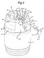
- FIG 2 shows the container 1 with the dispensing line 5 in the extended position, in which the shut-off valve 7 can be connected to the dispensing tap 19.
- a plate 30 forms a grip component that can be grasped by the user and that can be placed in the dispensing tap 19 in order to position the outlet end 6 accurately in the dispensing tap 19, as is shown diagrammatically in Fig. 1d .
- the dispensing line emerges through an extraction opening 31 from chamber 32, which is accommodated in central bridge 33.
- the central bridge 33 is located within a peripheral wall 36 of the container that has two hand grips 59, 60, located some distance away from the bridge 33, and two wall sections 40,40' which border the ends of the bridge 33.
- the dispensing line 5 is connected in the chamber 32 to the outlet 4 of the container 1.
- the extraction opening 31 is accessible via a cut-out 35 in the wall section 40 of the peripheral wall 36 of the cap 3 of the container.
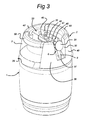
- a clamping element 39 in which the outlet end 6 can be accommodated, is positioned close to the extraction opening 31, as shown in Fig. 3 .
- the dispensing line 5 is housed in the chamber 32, whilst the plate 30 is located in the cut-out 35 in the peripheral wall 36.
- the outlet section 8 at right angles is positioned in a slot 37.
- the outlet end 6 is in a position that to a large extent corresponds to the position in which the outlet end 6 has to be placed in the dispensing tap 19, so that it is clear to a user how the dispensing line 5 and the outlet end 6 have to be brought into a use position that is shown in Fig. 1d and in Fig. 2 .
- the outlet end 6 of the dispensing line 5 is located in a second compartment 45 that is delimited by the surface of the cut-out 35 in the peripheral wall 36 of the cap 3 and by a top face 46 of the central bridge 33.
- the air connector 20 extends through a top wall 47 of the chamber 32 so that this can be connected to the coupling element 21 in the lid 25 of the dispensing device.
- Via an opening 48 in the top wall 47 the lid 25 is able on closing to engage, for example via the coupling element 21, on an operating element 51 (see Fig. 4 ) for opening the outlet 4.
- the second compartment 45 can be closed off by a removable protective cap or lid 52, as shown in Fig. 4 and Fig. 5 .
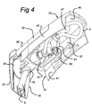
- Fig. 4 shows a perspective bottom view of the central bridge 33, side walls 41, 42 and the top wall 47 of which delimit the chamber 32.
- a tube section 53 at right angles is fitted on the end of the dispensing line 5 and, when the operating element 51 is pressed down, engages on a spring-loaded shut-off valve for the outlet 4. To this end, when the lid is closed, part of the lid 25 of the dispensing device extends through the top wall 47 of the chamber 32.
- the second compartment 45 is covered by the lid 52, the lid having two sections 54,55 at right angles which are essentially coincident with the plane of the peripheral wall 36 and with a top face 46 of the central bridge 33.
- Fig. 6 shows a side view of the container 1, provided with the two ears 13, 13', projecting laterally beyond the peripheral wall 14, and with two hand grips 59, 60, located on either side of central bridge 33, which can be used by a user to lift the container 1 and place it in the dispensing device.
- Fig. 7 shows a central bridge 33 that is constructed as an integral unit with the flexible dispensing line 5, the operating element 51 and air connector 20. Corresponding components in Fig. 7 are provided with the same reference numerals as in Figs 2-6 .
- the flexible dispensing line 5 extends from the operating element 51 towards the front short side 66 of the bridge 33.
- the dispensing line 5 then runs via a first bend 70 along a long side 67 of the bridge 33 and extends via a second bend 71 around the air connector 20, which is in line with the operating element 51.
- the dispensing line 5 runs further from the rear short side 65 of the bridge 33 to the front short side 66 via the second long side 68 of the bridge 33.
- the outlet end 6 is held in place by the clamping element 39 close to the open short side 66 of the chamber 32.
- the chamber 32 is closed off by the L-shaped lid 52.
- the arrangement shown can be efficiently assembled by machine, permanent deformation in the dispensing line 5 as a result of kinking or folding double being prevented.
- the gripper component 30 is in a position that is easily accessible for the user and that corresponds to the position in which the outlet end 6 has to be fitted in the dispensing device.
- the bridge 33 according to Fig. 7 that is constructed as an integral unit, can be clicked into the mid section of the top 2 of the container so that the opening 31 in the chamber 32 is coincident with the cut-out 35 in the wall section 40 and is closed off by the short section 54 of the lid 52.
- the connector 20 and the operating element 51 are placed in the correct position with respect to the lid 25 of the dispensing device 11, viewed in the longitudinal direction of the central bridge 33, by means of the cavities 29,29' in the ears 13,13'.
Landscapes
- Devices For Dispensing Beverages (AREA)
- Closures For Containers (AREA)
- Details Of Rigid Or Semi-Rigid Containers (AREA)
- Containers And Packaging Bodies Having A Special Means To Remove Contents (AREA)
- Filling Of Jars Or Cans And Processes For Cleaning And Sealing Jars (AREA)
- Supplying Of Containers To The Packaging Station (AREA)
- Bag Frames (AREA)
- Auxiliary Devices For And Details Of Packaging Control (AREA)
- Closing Of Containers (AREA)
Description
- The invention relates to an assembly comprising a container for drink, according to the preamble of
claim 1. - An assembly of this type is disclosed in
International Patent Application no. WO 99/11563 - One disadvantage of the known assembly is that access to the dispenser tube via the opening in the cap is relatively difficult for the user. Furthermore, positioning of the end of the tube in the dispensing tap of the dispensing device is relatively difficult.
- One aim of the invention is to provide an assembly comprising a container with which the flexible dispensing line can be hygienically fixed on the container during storage and transport of the container and with which the line can easily be placed in the use position by a user and can be connected to a dispensing tap of a dispensing device known per se. A further aim of the invention is to provide an assembly comprising a container with which the flexible dispensing line can be reliably housed in the container again after use.
- A further aim is to provide an assembly comprising a container that can easily be placed with the correct orientation in a dispensing device and which can be coupled in a simple manner to the dispensing device, such as to the dispensing tap and/or to the pressure medium feed.
- A few embodiments of an assembly comprising a container according to the invention will be explained in more detail with reference to the appended drawing. In the drawing:
-
Figs 1a, 1b and 1c, 1d show a cross-section and, respectively, a longitudinal section of an assembly of a container and a dispensing device, in a front view and a side view, respectively, -
Fig. 2 shows a container according toFig. 1 with the protective cap removed and with the dispensing line in the extended use position, it being possible for the outlet end to be fitted in a dispensing tap of the dispensing device, -
Fig. 3 shows a perspective view of the container according toFig. 2 , with protective cap removed, the dispensing line being placed in the accommodating chamber, -
Fig. 4 shows a perspective bottom view of a central bridge, with the accommodating chamber for the dispensing line, -
Fig. 5 shows a container according toFig. 3 with the protective cap fitted, in the storage and transport position, -
Fig. 6 shows a side view of a container according to the invention provided with positioning ears, -
Fig. 7 shows a perspective view of a chamber with the flexible dispensing line constructed as an integral unit, and -
Figures 1a - 1d show acontainer 1 that has been placed in adrink dispensing device 11. Thecontainer 1 is provided with a plastic outer jacket and at atop 2 has acap 3 attached to the outer jacket. Thecontainer 1 has an outlet 4, which can clearly be seen inFig. 1d . Aflexible dispensing line 5 is connected to the outlet 4, which dispensing line is provided at itsoutlet end 6 with a shut-offvalve 7 and with anoutlet section 8, made of relatively rigid plastic, at right angles. The shut-offvalve 7 is described in more detail inNetherlands Patent Application no. 1 015 368 tap 19 of thedispensing device 11. - The
dispensing device 11 is provided with achill chamber 12 for accommodating thecontainer 1. Thecontainer 1 has twoears 13,13' at its top, which ears protrude laterally with respect to theperipheral wall 14 of the container. Theears 13,13' bear on horizontal supportingsurfaces 15,15' ofstepped wall sections 16,16' in thechill chamber wall 17. In this way thecontainer 1 is correctly positioned with respect to the chill chamber, both in respect of height and in respect of angular position, so that thedispensing line 5 and the shut-offvalve 7 can be connected to the dispensingtap 19 of thedispensing device 11. Furthermore, theears 13,13' assist when positioning anair inlet 20 of thecontainer 1 with respect to acoupling element 21, arranged in thelid 25, of apressure line 22, which pressure line is connected to acompressor 23. As can be seen fromFigure 1b , thecoupling element 21 is located some distance from thecentre line 24, next to the central outlet 4. - When placing the
container 1 in thechill chamber 12 thelid 25 of thedispensing device 11 is open and thecontainer 1 is suspended in thechill chamber 12 by bringing theears 13, 13' to bear on the horizontal supportingsurfaces 15, 15'. As a result of this suspension in the dispensing device, containers of different heights can be used, the distance between the bottom 9' of the container and abase 9 of thechill chamber 12 being able to vary, for a constant and accurately defined position of theair inlet 20 and the outlet 4. - The distance between
opposing side walls stepped wall sections 16, 16' can decrease towards the base of thechill chamber 12 whilst therear walls wall sections 16, 16' can taper towards thecentre line 24. As a result thecontainer 1 can easily be placed through the top opening in thechill chamber 12 with theears 13, 13' in the broad positioning slots and the container itself seeks its correct orientation when it is lowered into the chill chamber. - The horizontal supporting
surfaces 15, 15' are provided withchamfered ridges 18, 18' which engage incavities 29,29' in theears 13,13' of thecontainer 1. The curvature of theridges 18, 18' is oriented in line with line L, seeFig. 1 , on which thecoupling element 21 for the air connector and the operating element for the spring-loaded shut-off valve of the outlet 4 are located, so that thecoupling element 21 in the lid and the operating element for the valve are aligned correctly with respect to the container. - After closing the
lid 25, thecompressor 23 is connected to theair inlet 20 and a spring-loaded shut-off valve of the outlet 4 is pressed down by a lid component, so that the outlet is opened and drink can be dispensed from thecontainer 1 under pressure via thedispensing tap 19 by opening and closing the shut-offvalve 7 by means of ahandle 10. -
Figure 2 shows thecontainer 1 with thedispensing line 5 in the extended position, in which the shut-offvalve 7 can be connected to thedispensing tap 19. With this arrangement aplate 30 forms a grip component that can be grasped by the user and that can be placed in the dispensingtap 19 in order to position theoutlet end 6 accurately in thedispensing tap 19, as is shown diagrammatically inFig. 1d . The dispensing line emerges through an extraction opening 31 fromchamber 32, which is accommodated incentral bridge 33. Thecentral bridge 33 is located within aperipheral wall 36 of the container that has twohand grips bridge 33, and twowall sections 40,40' which border the ends of thebridge 33. Thedispensing line 5 is connected in thechamber 32 to the outlet 4 of thecontainer 1. Theextraction opening 31 is accessible via a cut-out 35 in thewall section 40 of theperipheral wall 36 of thecap 3 of the container. Aclamping element 39, in which theoutlet end 6 can be accommodated, is positioned close to theextraction opening 31, as shown inFig. 3 . - In the storage and transport position that is shown in
Fig. 3 , thedispensing line 5 is housed in thechamber 32, whilst theplate 30 is located in the cut-out 35 in theperipheral wall 36. Theoutlet section 8 at right angles is positioned in aslot 37. As a result theoutlet end 6 is in a position that to a large extent corresponds to the position in which theoutlet end 6 has to be placed in the dispensingtap 19, so that it is clear to a user how the dispensingline 5 and theoutlet end 6 have to be brought into a use position that is shown inFig. 1d and inFig. 2 . - In the storage and transport position as shown in
Fig. 3 , theoutlet end 6 of thedispensing line 5 is located in asecond compartment 45 that is delimited by the surface of the cut-out 35 in theperipheral wall 36 of thecap 3 and by atop face 46 of thecentral bridge 33. In thesecond compartment 45 theair connector 20 extends through atop wall 47 of thechamber 32 so that this can be connected to thecoupling element 21 in thelid 25 of the dispensing device. Via anopening 48 in thetop wall 47 thelid 25 is able on closing to engage, for example via thecoupling element 21, on an operating element 51 (seeFig. 4 ) for opening the outlet 4. Thesecond compartment 45 can be closed off by a removable protective cap orlid 52, as shown inFig. 4 andFig. 5 . -
Fig. 4 shows a perspective bottom view of thecentral bridge 33,side walls top wall 47 of which delimit thechamber 32. Atube section 53 at right angles is fitted on the end of thedispensing line 5 and, when theoperating element 51 is pressed down, engages on a spring-loaded shut-off valve for the outlet 4. To this end, when the lid is closed, part of thelid 25 of the dispensing device extends through thetop wall 47 of thechamber 32. - As shown in
Fig. 5 thesecond compartment 45 is covered by thelid 52, the lid having twosections peripheral wall 36 and with atop face 46 of thecentral bridge 33. -
Fig. 6 shows a side view of thecontainer 1, provided with the twoears 13, 13', projecting laterally beyond theperipheral wall 14, and with twohand grips central bridge 33, which can be used by a user to lift thecontainer 1 and place it in the dispensing device. -
Fig. 7 shows acentral bridge 33 that is constructed as an integral unit with theflexible dispensing line 5, theoperating element 51 andair connector 20. Corresponding components inFig. 7 are provided with the same reference numerals as inFigs 2-6 . Theflexible dispensing line 5 extends from the operatingelement 51 towards the frontshort side 66 of thebridge 33. The dispensingline 5 then runs via afirst bend 70 along along side 67 of thebridge 33 and extends via asecond bend 71 around theair connector 20, which is in line with the operatingelement 51. The dispensingline 5 runs further from the rearshort side 65 of thebridge 33 to the frontshort side 66 via the secondlong side 68 of thebridge 33. Theoutlet end 6 is held in place by the clampingelement 39 close to the openshort side 66 of thechamber 32. Thechamber 32 is closed off by the L-shapedlid 52. The arrangement shown can be efficiently assembled by machine, permanent deformation in thedispensing line 5 as a result of kinking or folding double being prevented. After removal of thelid 52, thegripper component 30 is in a position that is easily accessible for the user and that corresponds to the position in which theoutlet end 6 has to be fitted in the dispensing device. - The
bridge 33 according toFig. 7 , that is constructed as an integral unit, can be clicked into the mid section of thetop 2 of the container so that theopening 31 in thechamber 32 is coincident with the cut-out 35 in thewall section 40 and is closed off by theshort section 54 of thelid 52. - The
connector 20 and the operatingelement 51 are placed in the correct position with respect to thelid 25 of the dispensingdevice 11, viewed in the longitudinal direction of thecentral bridge 33, by means of thecavities 29,29' in theears 13,13'.
Claims (5)
- Assembly comprising a container (1) for drink provided at a top (2) with a beverage outlet (4) situated on a centre line (24), which outlet (4) is connected to a flexible dispensing line (5) having an outlet end (6), and with a pressure medium inlet, characterized in that said pressure medium inlet is situated at a distance from the centre line (24) for receiving a pressure medium into the container and in that the assembly comprises a bridge (33) formed as an integral unit, the bridge is clicked onto the mid section of the container at the top (2) and has a pressure medium connector (20) for attaching to a pressure medium source on one side and on the other side connected to the pressure medium inlet of the container, and has an opening (48) via which an operating element (51) that is attached to an inflow end of the dispensing line (5) can be pressed down in the direction of the outlet (4) for opening of the outlet (4), wherein a chamber (32) is formed in the bridge (33), the flexible dispensing line being at least partially accommodated in the chamber (32), and having at an outflow end a grip component (30) that can be grasped by the user and that can be placed in a dispensing tap (19).
- Assembly according to claim 1, wherein the outlet end (6) of the flexible dispensing line (5) is connectable to a dispensing tap (19) for opening and closing of the dispensing line.
- Assembly according to claim 2, wherein the dispensing line (5) comprises at its outflow end a shut-off valve (7).
- Assembly according to any of the preceding claims, wherein the operating element is part of a tube section (53) at right angles to the dispensing line, which tube section (53) is displaceable relative to the opening in the bridge (33) by a user for opening of the outlet (4) prior to dispensing beverage from the container.
- Assembly according to any of the preceding claims, wherein the operating element (51) can be displaced for opening of the outlet (4) after the outlet end (6) of the dispensing line (5) has been placed in the tapping head and the tapping head has been closed.
Applications Claiming Priority (2)
| Application Number | Priority Date | Filing Date | Title |
|---|---|---|---|
| NL1015411A NL1015411C2 (en) | 2000-06-09 | 2000-06-09 | Beverage container provided with a chamber with a flexible dispensing line and with positioning means. |
| EP01941303A EP1286910B1 (en) | 2000-06-09 | 2001-06-11 | Container for drink provided with a chamber containing a flexible dispensing line |
Related Parent Applications (1)
| Application Number | Title | Priority Date | Filing Date |
|---|---|---|---|
| EP01941303A Division EP1286910B1 (en) | 2000-06-09 | 2001-06-11 | Container for drink provided with a chamber containing a flexible dispensing line |
Publications (3)
| Publication Number | Publication Date |
|---|---|
| EP1721863A2 EP1721863A2 (en) | 2006-11-15 |
| EP1721863A3 EP1721863A3 (en) | 2006-11-29 |
| EP1721863B1 true EP1721863B1 (en) | 2009-01-28 |
Family
ID=19771522
Family Applications (3)
| Application Number | Title | Priority Date | Filing Date |
|---|---|---|---|
| EP01941304A Expired - Lifetime EP1286911B1 (en) | 2000-06-09 | 2001-06-11 | Drink dispensing device and container for drink provided with positioning means |
| EP06115893A Expired - Lifetime EP1721863B1 (en) | 2000-06-09 | 2001-06-11 | Assembly comprising a container for drink |
| EP01941303A Expired - Lifetime EP1286910B1 (en) | 2000-06-09 | 2001-06-11 | Container for drink provided with a chamber containing a flexible dispensing line |
Family Applications Before (1)
| Application Number | Title | Priority Date | Filing Date |
|---|---|---|---|
| EP01941304A Expired - Lifetime EP1286911B1 (en) | 2000-06-09 | 2001-06-11 | Drink dispensing device and container for drink provided with positioning means |
Family Applications After (1)
| Application Number | Title | Priority Date | Filing Date |
|---|---|---|---|
| EP01941303A Expired - Lifetime EP1286910B1 (en) | 2000-06-09 | 2001-06-11 | Container for drink provided with a chamber containing a flexible dispensing line |
Country Status (37)
| Country | Link |
|---|---|
| US (4) | US20040118708A1 (en) |
| EP (3) | EP1286911B1 (en) |
| JP (1) | JP4739643B2 (en) |
| KR (1) | KR100821735B1 (en) |
| CN (2) | CN1272233C (en) |
| AP (1) | AP2002002682A0 (en) |
| AT (3) | ATE348786T1 (en) |
| AU (3) | AU2001274663A1 (en) |
| BG (1) | BG65743B1 (en) |
| BR (1) | BR0111498B1 (en) |
| CA (1) | CA2411862C (en) |
| CZ (1) | CZ301398B6 (en) |
| DE (3) | DE60137591D1 (en) |
| DK (2) | DK1286911T3 (en) |
| DZ (1) | DZ3369A1 (en) |
| EA (1) | EA005882B1 (en) |
| EC (1) | ECSP024405A (en) |
| EE (1) | EE04910B1 (en) |
| ES (2) | ES2247127T3 (en) |
| GE (1) | GEP20053554B (en) |
| HR (1) | HRP20020959B1 (en) |
| HU (1) | HU229169B1 (en) |
| IL (2) | IL153250A0 (en) |
| IS (1) | IS6650A (en) |
| MA (1) | MA26308A1 (en) |
| MX (1) | MXPA02012035A (en) |
| NL (1) | NL1015411C2 (en) |
| NO (1) | NO324098B1 (en) |
| NZ (1) | NZ523035A (en) |
| OA (1) | OA12383A (en) |
| PL (1) | PL196840B1 (en) |
| PT (1) | PT1286910E (en) |
| RS (1) | RS50187B (en) |
| SK (1) | SK287494B6 (en) |
| UA (1) | UA74831C2 (en) |
| WO (2) | WO2001094251A1 (en) |
| ZA (1) | ZA200209817B (en) |
Families Citing this family (46)
| Publication number | Priority date | Publication date | Assignee | Title |
|---|---|---|---|---|
| GB0227941D0 (en) * | 2002-11-29 | 2003-01-08 | Interbrew Sa | Beer line and flow restrictor |
| GB0203574D0 (en) * | 2002-02-15 | 2002-04-03 | Robinson David | Dispensing apparatus |
| US20060186136A1 (en) * | 2002-11-29 | 2006-08-24 | Albert Wauters | Beer dispensing apparatus |
| CN100558626C (en) * | 2003-05-06 | 2009-11-11 | 嘉士伯酿酒有限公司 | Method and apparatus for dispensing beverages |
| NL1023430C2 (en) | 2003-05-14 | 2004-11-16 | Heineken Tech Services | Beverage dispenser with a columnar cooling chamber. |
| GB0324905D0 (en) * | 2003-10-24 | 2003-11-26 | Interbrew Sa | Alcohol beverage appliance with gas connection |
| ATE430711T1 (en) * | 2004-09-13 | 2009-05-15 | Micro Matic As | DISPENSING LINE FOR A DISPENSING SYSTEM |
| US10631558B2 (en) | 2006-03-06 | 2020-04-28 | The Coca-Cola Company | Methods and apparatuses for making compositions comprising an acid and an acid degradable component and/or compositions comprising a plurality of selectable components |
| WO2008146240A2 (en) * | 2007-05-30 | 2008-12-04 | Koninklijke Philips Electronics N.V. | Paper-based beer container and dispensing apparatus therefor |
| US8162176B2 (en) | 2007-09-06 | 2012-04-24 | The Coca-Cola Company | Method and apparatuses for providing a selectable beverage |
| NL1034805C2 (en) * | 2007-12-10 | 2009-06-11 | Dispensing Technologies Bv | High-viscous product e.g. thick sauce, dispensing container, has bottle and plastic bag formed by two-component injection molding, and elongate member inserted into plastic bag through dispensing opening |
| DE102007055466A1 (en) * | 2007-11-13 | 2009-05-14 | Huber Packaging Group Gmbh + Co. Kg | Tap device |
| CA2708423A1 (en) * | 2007-12-10 | 2009-06-18 | Dispensing Technologies B.V. | Device for dosed dispensing of a liquid from a composite container and method for filling such a container with liquid |
| DE102008003934B4 (en) * | 2008-01-11 | 2010-05-27 | Carlsberg Breweries A/S | Beverage dispensing arrangement |
| EP2165968A1 (en) * | 2008-09-19 | 2010-03-24 | InBev S.A. | Bag-in-container with prepressurized space between inner bag and outer container |
| US8752734B2 (en) | 2009-02-11 | 2014-06-17 | Ds Smith Plastics Limited | Disposable assembly for a reusable urn or vessel |
| US20100252585A1 (en) * | 2009-04-01 | 2010-10-07 | Yui George M | Water probe for bottom loading water cooler |
| EP2669214B1 (en) | 2009-07-09 | 2016-01-20 | Advanced Technology Materials, Inc. | Storage system with a blow molded collapsible liner |
| WO2011006212A1 (en) * | 2009-07-16 | 2011-01-20 | Coopers Brewery Limited | Beverage dispensing apparatus |
| DE102009041115A1 (en) * | 2009-09-15 | 2011-03-31 | Fass-Frisch Gmbh | Pressure tapping attachment for beer containers and method of operating the same |
| SG10201508454WA (en) * | 2010-10-11 | 2015-11-27 | Advanced Tech Materials | Substantially rigid collapsible liner, container and/or liner for replacing glass bottles, and enhanced flexible liners |
| GB2485528B (en) * | 2010-11-09 | 2013-03-06 | Petainer Lidkoeping Ab | Keg closure with safety mechanism |
| US8714411B2 (en) | 2010-12-02 | 2014-05-06 | Back Road Ventures, Inc. | Portable fluid treatment and dispensing system |
| EP2681124A4 (en) | 2011-03-01 | 2015-05-27 | Advanced Tech Materials | EXTERNAL ENVELOPE AND INTERNAL BLOW MOLDED INTERNAL TRIM AND METHODS OF MANUFACTURING SAME |
| EP2514711A1 (en) * | 2011-04-18 | 2012-10-24 | Anheuser-Busch InBev S.A. | Liquid dispensing appliance comprising a solid gas-adsorbent |
| EP2909109B1 (en) * | 2012-10-19 | 2025-11-26 | Rust-Oleum Corporation | Propellantless aerosol system |
| DE102012111850A1 (en) * | 2012-12-05 | 2014-06-05 | Krones Ag | Device for emptying containers |
| US10051990B2 (en) | 2013-11-05 | 2018-08-21 | Plascon Group | Liner for a vessel |
| US10561272B2 (en) * | 2013-11-05 | 2020-02-18 | Plascon Packaging, Inc. | Selectively sealable liner for a vessel |
| US10227227B2 (en) | 2013-11-05 | 2019-03-12 | Plascon Group | Liner for a vessel |
| US10196254B2 (en) * | 2015-01-28 | 2019-02-05 | Pik Six LLC | Compact portable cooling container and keg dispenser |
| US9809238B2 (en) * | 2015-01-28 | 2017-11-07 | Pik Six LLC | Compact portable cooling container and keg dispenser |
| US10160583B2 (en) | 2015-05-27 | 2018-12-25 | Ds Smith Plastics Limited | Co-injection molded dispensing components |
| CN106330844B (en) * | 2015-07-02 | 2020-08-04 | 阿里巴巴集团控股有限公司 | Cross-terminal login-free method and device |
| US10112820B1 (en) * | 2016-01-19 | 2018-10-30 | Dss Rapak, Inc. | Beverage dispensing system with disposable liner and faucet |
| US9862589B2 (en) * | 2016-05-31 | 2018-01-09 | Starbucks Corporation | Chilled beverage dispenser |
| NL2017109B1 (en) * | 2016-07-05 | 2018-01-12 | Heineken Supply Chain Bv | Beverage dispensing assembly and beverage container |
| NL2018955B1 (en) * | 2017-05-19 | 2018-11-28 | Heineken Supply Chain Bv | Beverage dispensing assembly and beverage container |
| NL2018956B1 (en) * | 2017-05-19 | 2018-11-28 | Heineken Supply Chain Bv | Beverage dispensing assembly and beverage container |
| US11034569B2 (en) | 2018-02-14 | 2021-06-15 | Taphandles Llc | Cooled beverage dispensing systems and associated devices |
| BR102020024515A2 (en) * | 2020-11-30 | 2022-06-07 | Ambev S.A. | Container for carbonated beverage with beverage release system |
| BE1029639B1 (en) * | 2021-07-29 | 2023-02-27 | Anheuser Busch Inbev Sa | Barrel connector |
| CN114158936B (en) * | 2021-11-09 | 2024-04-19 | 杭州诺和健康科技有限公司 | Hydrogen-rich water dispenser |
| US12270600B2 (en) | 2022-01-05 | 2025-04-08 | Brumate, Inc. | Multi-function cooler |
| USD1087692S1 (en) | 2022-01-28 | 2025-08-12 | Anheuser-Busch Inbev S.A. | Tap for beer dispenser |
| CN114798579B (en) * | 2022-04-20 | 2023-03-14 | 常州爱特恩新材料科技有限公司 | Processing system of master batch is filled to plastics |
Family Cites Families (32)
| Publication number | Priority date | Publication date | Assignee | Title |
|---|---|---|---|---|
| US2104466A (en) * | 1933-08-24 | 1938-01-04 | Farwell Ozmun Kirk & Co | Refrigerating dispenser for beverages |
| US2792692A (en) * | 1955-09-21 | 1957-05-21 | Reed A Bryan | Keg cooler and dispensing bar unit |
| US3055556A (en) * | 1955-10-03 | 1962-09-25 | Dwight H Hester | Liquid dispenser |
| FR1256526A (en) * | 1959-03-20 | 1961-03-24 | Adjustable seat-sleeper chair | |
| FR1255526A (en) * | 1960-01-29 | 1961-03-10 | Gerodolle E | Beer dispenser bucket |
| US3317089A (en) * | 1966-03-18 | 1967-05-02 | John F Kopezynski | Liquid storing and dispensing device |
| US4120425A (en) * | 1972-09-01 | 1978-10-17 | The Champagne Machine Inc. | Apparatus for dispensing sparkling wines |
| US4429931A (en) * | 1981-10-26 | 1984-02-07 | Robert Brooks | Contained fire hose |
| US4726479A (en) * | 1986-12-08 | 1988-02-23 | Tsai Shung Der | Retractable sipper device for a portable thermos bottle |
| NL8700916A (en) * | 1987-04-16 | 1988-11-16 | Johan Hubertus Simons | MOVABLE BEER TAP. |
| US4886176A (en) * | 1988-10-25 | 1989-12-12 | Steakley Betty P | Portable liquid cooler |
| US5240144A (en) * | 1989-01-06 | 1993-08-31 | Joseph Feldman | Beverage dispensing apparatus |
| US5199609A (en) * | 1991-09-11 | 1993-04-06 | Ash Jr William O | Portable dispensing system |
| US5203468A (en) * | 1992-07-01 | 1993-04-20 | Hsu Chun Feng | Water container cap |
| DE4339889C1 (en) * | 1993-11-23 | 1995-04-20 | Henkel Kgaa | Closure for a liquid container, in particular for a bottle |
| US5540359A (en) * | 1995-10-16 | 1996-07-30 | Gobbel; Keith | Sprayer extension deivce |
| JP3710536B2 (en) * | 1995-12-19 | 2005-10-26 | ホシザキ電機株式会社 | Beverage container storage |
| DE19605756A1 (en) * | 1996-02-16 | 1997-08-21 | Joachim Mogler | Beer keg surrounded by bucket-shaped thermal insulation |
| US6041970A (en) * | 1996-08-30 | 2000-03-28 | Imi Cornelius Inc. | Pre-mix beverage dispensing system and components thereof |
| JP3844832B2 (en) * | 1997-02-07 | 2006-11-15 | サントリー株式会社 | Ice cooling server |
| US5897013A (en) * | 1997-04-14 | 1999-04-27 | Playtex Products, Inc. | Straw for drinking cup |
| JP3657393B2 (en) * | 1997-05-23 | 2005-06-08 | 株式会社吉野工業所 | Liquid storage container |
| JP3321798B2 (en) * | 1997-05-26 | 2002-09-09 | ツインバード工業株式会社 | Electronic refrigerator |
| NL1010015C2 (en) * | 1997-09-04 | 1999-05-10 | Heineken Tech Services | Tap assembly and container for fluid, especially beer or soft drink, to be dispensed via tap |
| EP1003686B1 (en) | 1997-09-04 | 2002-06-26 | Heineken Technical Services B.V. | Assembly for storing and dispensing beer and other carbonated beverages |
| DE69840304D1 (en) | 1997-09-04 | 2009-01-15 | Heineken Tech Services | Soda Fountain |
| NL1009654C2 (en) * | 1998-07-15 | 2000-01-19 | Heineken Tech Services | Valve assembly for a beverage container, container for beverage and method for filling and emptying a beverage container. |
| FR2792622B1 (en) * | 1999-04-23 | 2001-07-06 | Valois Sa | FLEXIBLE POCKET FLUID PRODUCT DISPENSER |
| MXPA02003784A (en) * | 1999-10-16 | 2002-12-13 | Glaxo Group Ltd | Device housing for an aerosol container. |
| US6481238B1 (en) * | 2001-08-13 | 2002-11-19 | Cold-Sell Systems, L.L.C. | Keg server |
| NL1019054C2 (en) * | 2001-09-28 | 2003-03-31 | Heineken Tech Services | Beverage dispensing device provided with a double closure. |
| JP4006332B2 (en) * | 2002-12-26 | 2007-11-14 | 勝利 増田 | Fluid storage container |
-
2000
- 2000-06-09 NL NL1015411A patent/NL1015411C2/en not_active IP Right Cessation
-
2001
- 2001-06-11 EP EP01941304A patent/EP1286911B1/en not_active Expired - Lifetime
- 2001-06-11 EE EEP200200676A patent/EE04910B1/en not_active IP Right Cessation
- 2001-06-11 RS YUP-924/02A patent/RS50187B/en unknown
- 2001-06-11 GE GE5035A patent/GEP20053554B/en unknown
- 2001-06-11 BR BRPI0111498-0A patent/BR0111498B1/en not_active IP Right Cessation
- 2001-06-11 WO PCT/NL2001/000438 patent/WO2001094251A1/en not_active Ceased
- 2001-06-11 CZ CZ20023982A patent/CZ301398B6/en not_active IP Right Cessation
- 2001-06-11 AT AT01941303T patent/ATE348786T1/en active
- 2001-06-11 SK SK1766-2002A patent/SK287494B6/en not_active IP Right Cessation
- 2001-06-11 IL IL15325001A patent/IL153250A0/en active IP Right Grant
- 2001-06-11 AU AU2001274663A patent/AU2001274663A1/en not_active Abandoned
- 2001-06-11 HR HR20020959A patent/HRP20020959B1/en not_active IP Right Cessation
- 2001-06-11 DE DE60137591T patent/DE60137591D1/en not_active Expired - Lifetime
- 2001-06-11 DE DE60125355T patent/DE60125355T2/en not_active Expired - Lifetime
- 2001-06-11 DK DK01941304T patent/DK1286911T3/en active
- 2001-06-11 AP APAP/P/2002/002682A patent/AP2002002682A0/en unknown
- 2001-06-11 MX MXPA02012035A patent/MXPA02012035A/en active IP Right Grant
- 2001-06-11 ES ES01941304T patent/ES2247127T3/en not_active Expired - Lifetime
- 2001-06-11 CA CA2411862A patent/CA2411862C/en not_active Expired - Fee Related
- 2001-06-11 JP JP2002501774A patent/JP4739643B2/en not_active Expired - Fee Related
- 2001-06-11 OA OA1200200373A patent/OA12383A/en unknown
- 2001-06-11 WO PCT/NL2001/000437 patent/WO2001094250A1/en not_active Ceased
- 2001-06-11 PL PL358922A patent/PL196840B1/en not_active IP Right Cessation
- 2001-06-11 AT AT06115893T patent/ATE421946T1/en not_active IP Right Cessation
- 2001-06-11 DE DE60114612T patent/DE60114612T2/en not_active Expired - Lifetime
- 2001-06-11 US US10/297,719 patent/US20040118708A1/en not_active Abandoned
- 2001-06-11 PT PT01941303T patent/PT1286910E/en unknown
- 2001-06-11 HU HU0301086A patent/HU229169B1/en not_active IP Right Cessation
- 2001-06-11 EP EP06115893A patent/EP1721863B1/en not_active Expired - Lifetime
- 2001-06-11 DK DK01941303T patent/DK1286910T3/en active
- 2001-06-11 EP EP01941303A patent/EP1286910B1/en not_active Expired - Lifetime
- 2001-06-11 AU AU2001274664A patent/AU2001274664B2/en not_active Ceased
- 2001-06-11 NZ NZ523035A patent/NZ523035A/en not_active IP Right Cessation
- 2001-06-11 CN CNB018107753A patent/CN1272233C/en not_active Expired - Fee Related
- 2001-06-11 KR KR1020027016635A patent/KR100821735B1/en not_active Expired - Fee Related
- 2001-06-11 US US10/297,717 patent/US7100803B2/en not_active Expired - Lifetime
- 2001-06-11 DZ DZ013369A patent/DZ3369A1/en active
- 2001-06-11 ES ES01941303T patent/ES2277927T3/en not_active Expired - Lifetime
- 2001-06-11 CN CNA2006101054555A patent/CN1911778A/en active Pending
- 2001-06-11 AT AT01941304T patent/ATE308481T1/en active
- 2001-06-11 EA EA200300011A patent/EA005882B1/en not_active IP Right Cessation
- 2001-06-11 AU AU7466401A patent/AU7466401A/en active Pending
- 2001-11-06 UA UA2003010240A patent/UA74831C2/en unknown
-
2002
- 2002-12-03 ZA ZA200209817A patent/ZA200209817B/en unknown
- 2002-12-03 IL IL153250A patent/IL153250A/en not_active IP Right Cessation
- 2002-12-04 NO NO20025820A patent/NO324098B1/en not_active IP Right Cessation
- 2002-12-06 IS IS6650A patent/IS6650A/en unknown
- 2002-12-09 BG BG107363A patent/BG65743B1/en unknown
- 2002-12-09 MA MA26941A patent/MA26308A1/en unknown
- 2002-12-26 EC EC2002004405A patent/ECSP024405A/en unknown
-
2006
- 2006-06-26 US US11/474,447 patent/US20070084883A1/en not_active Abandoned
- 2006-07-21 US US11/490,074 patent/US7237696B2/en not_active Expired - Lifetime
Also Published As
Similar Documents
| Publication | Publication Date | Title |
|---|---|---|
| EP1286910B1 (en) | Container for drink provided with a chamber containing a flexible dispensing line | |
| AU2001274664A1 (en) | Drink dispensing device and container for drink provided with positioning means | |
| EP1473271A3 (en) | Drink dispenser assembly and container for drink and drink dispensing line | |
| KR20030027842A (en) | Beverage dispensing device provided with a dual closure | |
| EP2467327A1 (en) | A bag-in-box dispensing spout capture mechanism | |
| US7246727B2 (en) | Container for drink provided with a chamber containing a flexible dispensing line | |
| HK1050671B (en) | Container for drink provided with a chamber containing a flexible dispensing line | |
| HK1050670B (en) | Drink dispensing device and container for drink provided with positioning means | |
| JP2002255240A (en) | Outer container to be fitted on soft container storing liquid |
Legal Events
| Date | Code | Title | Description |
|---|---|---|---|
| PUAI | Public reference made under article 153(3) epc to a published international application that has entered the european phase |
Free format text: ORIGINAL CODE: 0009012 |
|
| PUAL | Search report despatched |
Free format text: ORIGINAL CODE: 0009013 |
|
| AC | Divisional application: reference to earlier application |
Ref document number: 1286910 Country of ref document: EP Kind code of ref document: P |
|
| AK | Designated contracting states |
Kind code of ref document: A2 Designated state(s): AT BE CH CY DE DK ES FI FR GB GR IE IT LI LU MC NL PT SE TR |
|
| AK | Designated contracting states |
Kind code of ref document: A3 Designated state(s): AT BE CH CY DE DK ES FI FR GB GR IE IT LI LU MC NL PT SE TR |
|
| RIN1 | Information on inventor provided before grant (corrected) |
Inventor name: MAGERMANS, MARCEL PETER Inventor name: TIMP, PIET HEIN WILLEM |
|
| 17P | Request for examination filed |
Effective date: 20070529 |
|
| AKX | Designation fees paid |
Designated state(s): AT BE CH CY DE DK ES FI FR GB GR IE IT LI LU MC NL PT SE TR |
|
| 17Q | First examination report despatched |
Effective date: 20070917 |
|
| GRAP | Despatch of communication of intention to grant a patent |
Free format text: ORIGINAL CODE: EPIDOSNIGR1 |
|
| RTI1 | Title (correction) |
Free format text: ASSEMBLY COMPRISING A CONTAINER FOR DRINK |
|
| GRAS | Grant fee paid |
Free format text: ORIGINAL CODE: EPIDOSNIGR3 |
|
| GRAA | (expected) grant |
Free format text: ORIGINAL CODE: 0009210 |
|
| AC | Divisional application: reference to earlier application |
Ref document number: 1286910 Country of ref document: EP Kind code of ref document: P |
|
| AK | Designated contracting states |
Kind code of ref document: B1 Designated state(s): AT BE CH CY DE DK ES FI FR GB GR IE IT LI LU MC NL PT SE TR |
|
| REG | Reference to a national code |
Ref country code: GB Ref legal event code: FG4D |
|
| REG | Reference to a national code |
Ref country code: CH Ref legal event code: EP |
|
| REG | Reference to a national code |
Ref country code: IE Ref legal event code: FG4D |
|
| REF | Corresponds to: |
Ref document number: 60137591 Country of ref document: DE Date of ref document: 20090319 Kind code of ref document: P |
|
| PG25 | Lapsed in a contracting state [announced via postgrant information from national office to epo] |
Ref country code: FI Free format text: LAPSE BECAUSE OF FAILURE TO SUBMIT A TRANSLATION OF THE DESCRIPTION OR TO PAY THE FEE WITHIN THE PRESCRIBED TIME-LIMIT Effective date: 20090128 Ref country code: ES Free format text: LAPSE BECAUSE OF FAILURE TO SUBMIT A TRANSLATION OF THE DESCRIPTION OR TO PAY THE FEE WITHIN THE PRESCRIBED TIME-LIMIT Effective date: 20090509 |
|
| PG25 | Lapsed in a contracting state [announced via postgrant information from national office to epo] |
Ref country code: AT Free format text: LAPSE BECAUSE OF FAILURE TO SUBMIT A TRANSLATION OF THE DESCRIPTION OR TO PAY THE FEE WITHIN THE PRESCRIBED TIME-LIMIT Effective date: 20090128 Ref country code: SE Free format text: LAPSE BECAUSE OF FAILURE TO SUBMIT A TRANSLATION OF THE DESCRIPTION OR TO PAY THE FEE WITHIN THE PRESCRIBED TIME-LIMIT Effective date: 20090428 Ref country code: PT Free format text: LAPSE BECAUSE OF FAILURE TO SUBMIT A TRANSLATION OF THE DESCRIPTION OR TO PAY THE FEE WITHIN THE PRESCRIBED TIME-LIMIT Effective date: 20090629 |
|
| PG25 | Lapsed in a contracting state [announced via postgrant information from national office to epo] |
Ref country code: DK Free format text: LAPSE BECAUSE OF FAILURE TO SUBMIT A TRANSLATION OF THE DESCRIPTION OR TO PAY THE FEE WITHIN THE PRESCRIBED TIME-LIMIT Effective date: 20090128 |
|
| PLBE | No opposition filed within time limit |
Free format text: ORIGINAL CODE: 0009261 |
|
| STAA | Information on the status of an ep patent application or granted ep patent |
Free format text: STATUS: NO OPPOSITION FILED WITHIN TIME LIMIT |
|
| 26N | No opposition filed |
Effective date: 20091029 |
|
| PG25 | Lapsed in a contracting state [announced via postgrant information from national office to epo] |
Ref country code: MC Free format text: LAPSE BECAUSE OF NON-PAYMENT OF DUE FEES Effective date: 20090630 |
|
| REG | Reference to a national code |
Ref country code: CH Ref legal event code: PL |
|
| GBPC | Gb: european patent ceased through non-payment of renewal fee |
Effective date: 20090611 |
|
| REG | Reference to a national code |
Ref country code: FR Ref legal event code: ST Effective date: 20100226 |
|
| REG | Reference to a national code |
Ref country code: IE Ref legal event code: MM4A |
|
| PG25 | Lapsed in a contracting state [announced via postgrant information from national office to epo] |
Ref country code: IE Free format text: LAPSE BECAUSE OF NON-PAYMENT OF DUE FEES Effective date: 20090611 Ref country code: CH Free format text: LAPSE BECAUSE OF NON-PAYMENT OF DUE FEES Effective date: 20090630 Ref country code: LI Free format text: LAPSE BECAUSE OF NON-PAYMENT OF DUE FEES Effective date: 20090630 Ref country code: FR Free format text: LAPSE BECAUSE OF NON-PAYMENT OF DUE FEES Effective date: 20090630 |
|
| PG25 | Lapsed in a contracting state [announced via postgrant information from national office to epo] |
Ref country code: GB Free format text: LAPSE BECAUSE OF NON-PAYMENT OF DUE FEES Effective date: 20090611 |
|
| PG25 | Lapsed in a contracting state [announced via postgrant information from national office to epo] |
Ref country code: GR Free format text: LAPSE BECAUSE OF FAILURE TO SUBMIT A TRANSLATION OF THE DESCRIPTION OR TO PAY THE FEE WITHIN THE PRESCRIBED TIME-LIMIT Effective date: 20090429 |
|
| PG25 | Lapsed in a contracting state [announced via postgrant information from national office to epo] |
Ref country code: IT Free format text: LAPSE BECAUSE OF FAILURE TO SUBMIT A TRANSLATION OF THE DESCRIPTION OR TO PAY THE FEE WITHIN THE PRESCRIBED TIME-LIMIT Effective date: 20090128 |
|
| PG25 | Lapsed in a contracting state [announced via postgrant information from national office to epo] |
Ref country code: LU Free format text: LAPSE BECAUSE OF NON-PAYMENT OF DUE FEES Effective date: 20090611 |
|
| PG25 | Lapsed in a contracting state [announced via postgrant information from national office to epo] |
Ref country code: TR Free format text: LAPSE BECAUSE OF FAILURE TO SUBMIT A TRANSLATION OF THE DESCRIPTION OR TO PAY THE FEE WITHIN THE PRESCRIBED TIME-LIMIT Effective date: 20090128 |
|
| PG25 | Lapsed in a contracting state [announced via postgrant information from national office to epo] |
Ref country code: CY Free format text: LAPSE BECAUSE OF FAILURE TO SUBMIT A TRANSLATION OF THE DESCRIPTION OR TO PAY THE FEE WITHIN THE PRESCRIBED TIME-LIMIT Effective date: 20090128 |
|
| PGFP | Annual fee paid to national office [announced via postgrant information from national office to epo] |
Ref country code: DE Payment date: 20160621 Year of fee payment: 16 |
|
| PGFP | Annual fee paid to national office [announced via postgrant information from national office to epo] |
Ref country code: BE Payment date: 20160620 Year of fee payment: 16 Ref country code: NL Payment date: 20160620 Year of fee payment: 16 |
|
| REG | Reference to a national code |
Ref country code: DE Ref legal event code: R119 Ref document number: 60137591 Country of ref document: DE |
|
| REG | Reference to a national code |
Ref country code: NL Ref legal event code: MM Effective date: 20170701 |
|
| PG25 | Lapsed in a contracting state [announced via postgrant information from national office to epo] |
Ref country code: NL Free format text: LAPSE BECAUSE OF NON-PAYMENT OF DUE FEES Effective date: 20170701 |
|
| PG25 | Lapsed in a contracting state [announced via postgrant information from national office to epo] |
Ref country code: DE Free format text: LAPSE BECAUSE OF NON-PAYMENT OF DUE FEES Effective date: 20180103 |
|
| REG | Reference to a national code |
Ref country code: BE Ref legal event code: MM Effective date: 20170630 |
|
| PG25 | Lapsed in a contracting state [announced via postgrant information from national office to epo] |
Ref country code: BE Free format text: LAPSE BECAUSE OF NON-PAYMENT OF DUE FEES Effective date: 20170630 |