EP1721079B1 - System und verfahren zum schraubenverdichterbetrieb mit veränderlicher geschwindigkeit - Google Patents
System und verfahren zum schraubenverdichterbetrieb mit veränderlicher geschwindigkeit Download PDFInfo
- Publication number
- EP1721079B1 EP1721079B1 EP05723850.3A EP05723850A EP1721079B1 EP 1721079 B1 EP1721079 B1 EP 1721079B1 EP 05723850 A EP05723850 A EP 05723850A EP 1721079 B1 EP1721079 B1 EP 1721079B1
- Authority
- EP
- European Patent Office
- Prior art keywords
- motor
- output
- frequency
- predetermined
- voltage
- Prior art date
- Legal status (The legal status is an assumption and is not a legal conclusion. Google has not performed a legal analysis and makes no representation as to the accuracy of the status listed.)
- Expired - Lifetime
Links
Images

Classifications
-
- H—ELECTRICITY
- H02—GENERATION; CONVERSION OR DISTRIBUTION OF ELECTRIC POWER
- H02P—CONTROL OR REGULATION OF ELECTRIC MOTORS, ELECTRIC GENERATORS OR DYNAMO-ELECTRIC CONVERTERS; CONTROLLING TRANSFORMERS, REACTORS OR CHOKE COILS
- H02P27/00—Arrangements or methods for the control of AC motors characterised by the kind of supply voltage
- H02P27/04—Arrangements or methods for the control of AC motors characterised by the kind of supply voltage using variable-frequency supply voltage, e.g. inverter or converter supply voltage
-
- F—MECHANICAL ENGINEERING; LIGHTING; HEATING; WEAPONS; BLASTING
- F04—POSITIVE - DISPLACEMENT MACHINES FOR LIQUIDS; PUMPS FOR LIQUIDS OR ELASTIC FLUIDS
- F04C—ROTARY-PISTON, OR OSCILLATING-PISTON, POSITIVE-DISPLACEMENT MACHINES FOR LIQUIDS; ROTARY-PISTON, OR OSCILLATING-PISTON, POSITIVE-DISPLACEMENT PUMPS
- F04C18/00—Rotary-piston pumps specially adapted for elastic fluids
- F04C18/08—Rotary-piston pumps specially adapted for elastic fluids of intermeshing-engagement type, i.e. with engagement of co-operating members similar to that of toothed gearing
- F04C18/12—Rotary-piston pumps specially adapted for elastic fluids of intermeshing-engagement type, i.e. with engagement of co-operating members similar to that of toothed gearing of other than internal-axis type
- F04C18/14—Rotary-piston pumps specially adapted for elastic fluids of intermeshing-engagement type, i.e. with engagement of co-operating members similar to that of toothed gearing of other than internal-axis type with toothed rotary pistons
- F04C18/16—Rotary-piston pumps specially adapted for elastic fluids of intermeshing-engagement type, i.e. with engagement of co-operating members similar to that of toothed gearing of other than internal-axis type with toothed rotary pistons with helical teeth, e.g. chevron-shaped, screw type
-
- F—MECHANICAL ENGINEERING; LIGHTING; HEATING; WEAPONS; BLASTING
- F04—POSITIVE - DISPLACEMENT MACHINES FOR LIQUIDS; PUMPS FOR LIQUIDS OR ELASTIC FLUIDS
- F04C—ROTARY-PISTON, OR OSCILLATING-PISTON, POSITIVE-DISPLACEMENT MACHINES FOR LIQUIDS; ROTARY-PISTON, OR OSCILLATING-PISTON, POSITIVE-DISPLACEMENT PUMPS
- F04C28/00—Control of, monitoring of, or safety arrangements for, pumps or pumping installations specially adapted for elastic fluids
- F04C28/08—Control of, monitoring of, or safety arrangements for, pumps or pumping installations specially adapted for elastic fluids characterised by varying the rotational speed
-
- F—MECHANICAL ENGINEERING; LIGHTING; HEATING; WEAPONS; BLASTING
- F04—POSITIVE - DISPLACEMENT MACHINES FOR LIQUIDS; PUMPS FOR LIQUIDS OR ELASTIC FLUIDS
- F04C—ROTARY-PISTON, OR OSCILLATING-PISTON, POSITIVE-DISPLACEMENT MACHINES FOR LIQUIDS; ROTARY-PISTON, OR OSCILLATING-PISTON, POSITIVE-DISPLACEMENT PUMPS
- F04C29/00—Component parts, details or accessories of pumps or pumping installations, not provided for in groups F04C18/00 - F04C28/00
- F04C29/0042—Driving elements, brakes, couplings, transmissions specially adapted for pumps
- F04C29/0085—Prime movers
-
- F—MECHANICAL ENGINEERING; LIGHTING; HEATING; WEAPONS; BLASTING
- F25—REFRIGERATION OR COOLING; COMBINED HEATING AND REFRIGERATION SYSTEMS; HEAT PUMP SYSTEMS; MANUFACTURE OR STORAGE OF ICE; LIQUEFACTION SOLIDIFICATION OF GASES
- F25B—REFRIGERATION MACHINES, PLANTS OR SYSTEMS; COMBINED HEATING AND REFRIGERATION SYSTEMS; HEAT PUMP SYSTEMS
- F25B49/00—Arrangement or mounting of control or safety devices
- F25B49/02—Arrangement or mounting of control or safety devices for compression type machines, plants or systems
- F25B49/025—Motor control arrangements
-
- F—MECHANICAL ENGINEERING; LIGHTING; HEATING; WEAPONS; BLASTING
- F25—REFRIGERATION OR COOLING; COMBINED HEATING AND REFRIGERATION SYSTEMS; HEAT PUMP SYSTEMS; MANUFACTURE OR STORAGE OF ICE; LIQUEFACTION SOLIDIFICATION OF GASES
- F25B—REFRIGERATION MACHINES, PLANTS OR SYSTEMS; COMBINED HEATING AND REFRIGERATION SYSTEMS; HEAT PUMP SYSTEMS
- F25B1/00—Compression machines, plants or systems with non-reversible cycle
- F25B1/04—Compression machines, plants or systems with non-reversible cycle with compressor of rotary type
- F25B1/047—Compression machines, plants or systems with non-reversible cycle with compressor of rotary type of screw type
-
- F—MECHANICAL ENGINEERING; LIGHTING; HEATING; WEAPONS; BLASTING
- F25—REFRIGERATION OR COOLING; COMBINED HEATING AND REFRIGERATION SYSTEMS; HEAT PUMP SYSTEMS; MANUFACTURE OR STORAGE OF ICE; LIQUEFACTION SOLIDIFICATION OF GASES
- F25B—REFRIGERATION MACHINES, PLANTS OR SYSTEMS; COMBINED HEATING AND REFRIGERATION SYSTEMS; HEAT PUMP SYSTEMS
- F25B2400/00—General features or devices for refrigeration machines, plants or systems, combined heating and refrigeration systems or heat-pump systems, i.e. not limited to a particular subgroup of F25B
- F25B2400/07—Details of compressors or related parts
- F25B2400/075—Details of compressors or related parts with parallel compressors
-
- F—MECHANICAL ENGINEERING; LIGHTING; HEATING; WEAPONS; BLASTING
- F25—REFRIGERATION OR COOLING; COMBINED HEATING AND REFRIGERATION SYSTEMS; HEAT PUMP SYSTEMS; MANUFACTURE OR STORAGE OF ICE; LIQUEFACTION SOLIDIFICATION OF GASES
- F25B—REFRIGERATION MACHINES, PLANTS OR SYSTEMS; COMBINED HEATING AND REFRIGERATION SYSTEMS; HEAT PUMP SYSTEMS
- F25B2400/00—General features or devices for refrigeration machines, plants or systems, combined heating and refrigeration systems or heat-pump systems, i.e. not limited to a particular subgroup of F25B
- F25B2400/13—Economisers
-
- F—MECHANICAL ENGINEERING; LIGHTING; HEATING; WEAPONS; BLASTING
- F25—REFRIGERATION OR COOLING; COMBINED HEATING AND REFRIGERATION SYSTEMS; HEAT PUMP SYSTEMS; MANUFACTURE OR STORAGE OF ICE; LIQUEFACTION SOLIDIFICATION OF GASES
- F25B—REFRIGERATION MACHINES, PLANTS OR SYSTEMS; COMBINED HEATING AND REFRIGERATION SYSTEMS; HEAT PUMP SYSTEMS
- F25B2600/00—Control issues
- F25B2600/02—Compressor control
- F25B2600/025—Compressor control by controlling speed
- F25B2600/0253—Compressor control by controlling speed with variable speed
-
- Y—GENERAL TAGGING OF NEW TECHNOLOGICAL DEVELOPMENTS; GENERAL TAGGING OF CROSS-SECTIONAL TECHNOLOGIES SPANNING OVER SEVERAL SECTIONS OF THE IPC; TECHNICAL SUBJECTS COVERED BY FORMER USPC CROSS-REFERENCE ART COLLECTIONS [XRACs] AND DIGESTS
- Y02—TECHNOLOGIES OR APPLICATIONS FOR MITIGATION OR ADAPTATION AGAINST CLIMATE CHANGE
- Y02B—CLIMATE CHANGE MITIGATION TECHNOLOGIES RELATED TO BUILDINGS, e.g. HOUSING, HOUSE APPLIANCES OR RELATED END-USER APPLICATIONS
- Y02B30/00—Energy efficient heating, ventilation or air conditioning [HVAC]
- Y02B30/70—Efficient control or regulation technologies, e.g. for control of refrigerant flow, motor or heating
Definitions
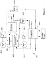
- the liquid refrigerant in the coils of the separate refrigerant circuits of the evaporator system 410 enter into a heat exchange relationship with the secondary liquid to chill the temperature of the secondary liquid.
- the refrigerant liquid in the coils of the evaporator system 410 undergoes a phase change to a refrigerant vapor as a result of the heat exchange relationship with the secondary liquid.
- the vapor refrigerant in the coils of the evaporator system 410 exits the evaporator system 410 and returns to the corresponding compressor 402 of the refrigerant circuit by a suction line to complete the cycle.
Landscapes
- Engineering & Computer Science (AREA)
- Mechanical Engineering (AREA)
- General Engineering & Computer Science (AREA)
- Physics & Mathematics (AREA)
- Thermal Sciences (AREA)
- Power Engineering (AREA)
- Applications Or Details Of Rotary Compressors (AREA)
Claims (32)
- Verfahren zum Steigern eines Leistungsvermögens eines Schraubenkompressors (108), wobei das Verfahren die folgenden Schritte umfasst:Bereitstellen eines Motors (106), der eine vorbestimmte Nennbetriebsspannung und -frequenz aufweist, wobei die vorbestimmte Nennbetriebsspannung und -frequenz des Motors (106) eine vorbestimmte Abtriebsdrehzahl des Motors (106) erzeugt,Bereitstellen eines Antriebs (104) mit veränderlicher Drehzahl, der dazu in der Lage ist, dem Motor (106) eine Spannung und Frequenz bereitzustellen, die größer sind als die vorbestimmte Nennbetriebsspannung und -frequenz des Motors (106),Verbinden eines Schraubenkompressors (108) mit dem Motor (106), wobei der Schraubenkompressor (108) ein vorbestimmtes Leistungsvermögen als Reaktion auf den Betrieb mit der vorbestimmten Abtriebsdrehzahl des Motors (106) aufweist, undAntreiben des Schraubenkompressors (108) mit einer erzeugten Abtriebsdrehzahl des Motors (106), die größer ist als die vorbestimmte Abtriebsdrehzahl des Motors (106), um ein Leistungsvermögen von dem Schraubenkompressor (108) zu erhalten, das größer ist als das vorbestimmte Leistungsvermögen des Schraubenkompressors (108),gekennzeichnet durchBetreiben des Antriebs (104) mit veränderlicher Drehzahl, um dem Motor (106) eine Spannung und Frequenz bereitzustellen, die größer sind als die vorbestimmte Nennbetriebsspannung und -frequenz des Motors (106), wobei der Motor (106) im Ergebnis dessen, dass die dem Motor (106) bereitgestellte Spannung und Frequenz größer sind als die vorbestimmte Nennbetriebsspannung und - frequenz des Motors (106), eine Abtriebsdrehzahl erzeugt, die größer ist als die vorbestimmte Abtriebsdrehzahl des Motors (106), undErhöhen der Ausgangsspannung des Antriebs (104) mit veränderlicher Drehzahl so, dass sie wenigstens das Doppelte einer Eingangsspannung für den Antrieb (104) mit veränderlicher Drehzahl beträgt.
- Verfahren nach Anspruch 1, das ferner den Schritt des Betreibens des Motors (106) in einem Betriebsmodus mit konstantem Fluss umfasst.
- Verfahren nach Anspruch 1, wobei die vorbestimmte Nennbetriebsspannung des Motors (106) im Wesentlichen gleich der Eingangsspannung des Antriebs (104) mit veränderlicher Drehzahl ist.
- Verfahren nach Anspruch 1, wobei die vorbestimmte Nennbetriebsspannung des Motors (106) im Wesentlichen geringer ist als die Eingangsspannung des Antriebs (104) mit veränderlicher Drehzahl.
- Verfahren nach Anspruch 1, das ferner den Schritt des Entfernens eines Schiebers zur Leistungsregelung von dem Schraubenkompressor (108) umfasst.
- Verdichtungsanlage, die Folgendes umfasst:einen Motor (106), der eine vorbestimmte Nennbetriebsspannung und -frequenz aufweist, wobei der Motor (106) dafür konfiguriert ist, als Reaktion auf einen Betrieb mit der vorbestimmten Nennbetriebsspannung und -frequenz eine vorbestimmte Abtriebsdrehzahl zu erzeugen,einen Antrieb (104) mit veränderlicher Drehzahl, der mit dem Motor (106) verbunden ist, um den Motor (106) zu speisen, wobei der Antrieb (104) mit veränderlicher Drehzahl dafür konfiguriert ist, dem Motor (106) eine veränderliche Ausgangsspannung und eine veränderliche Ausgangsfrequenz zuzuführen, wobei die veränderliche Ausgangsspannung und die veränderliche Ausgangsfrequenz zwischen einer Ausgangsspannung und einer Ausgangsfrequenz, die geringer sind als die vorbestimmte Nennbetriebsspannung und -frequenz und einer Ausgangsspannung und einer Ausgangsfrequenz, die größer sind als die vorbestimmte Nennbetriebsspannung und -frequenz, schwanken,einen Schraubenkompressor (108), der mit dem Motor (106) verbunden ist, wobei der Schraubenkompressor (108) dafür konfiguriert ist, als Reaktion darauf, dass er mit der vorbestimmten Abtriebsdrehzahl des Motors (106) angetrieben wird, ein vorbestimmtes Leistungsvermögen bereitzustellen, unddadurch gekennzeichnet, dassder Motor (106) als Reaktion auf einen Betrieb mit einer zugeführten Spannung und Frequenz, die größer sind als die vorbestimmte Nennbetriebsspannung und -frequenz, eine Abtriebsdrehzahl erzeugt, die größer ist als die vorbestimmte Abtriebsdrehzahl, und der Schraubenkompressor (108) als Reaktion darauf, dass er mit einer Abtriebsdrehzahl des Motors (106) angetrieben wird, die größer ist als die vorbestimmte Abtriebsdrehzahl des Motors (106), ein Leistungsvermögen bereitstellt, das größer ist als das vorbestimmte Leistungsvermögen,wobei der Antrieb (104) mit veränderlicher Drehzahl dafür konfiguriert ist, dem Motor (106) eine Ausgangsspannung bereitzustellen, die wenigstens das Doppelte der Eingangsspannung für den Antrieb (104) mit veränderlicher Drehzahl beträgt.
- Verdichtungsanlage nach Anspruch 6, wobei die vorbestimmte Nennbetriebsspannung des Motors (106) im Wesentlichen gleich der Eingangsspannung des Antriebs (104) mit veränderlicher Drehzahl ist.
- Verdichtungsanlage nach Anspruch 6, wobei die vorbestimmte Nennbetriebsspannung des Motors (106) im Wesentlichen geringer ist als die Eingangsspannung des Antriebs (104) mit veränderlicher Drehzahl.
- Verdichtungsanlage nach Anspruch 6, wobei der Antrieb (104) mit veränderlicher Drehzahl dem Motor (106) eine Ausgangsspannung und eine Ausgangsfrequenz zuführt, um zu ermöglichen, dass der Motor in einem Betriebsmodus mit konstantem Fluss arbeitet.
- Verdichtungsanlage nach Anspruch 6, wobei der Schraubenkompressor (108) als Reaktion darauf, dass er mit einer Abtriebsdrehzahl des Motors (106) angetrieben wird, die größer ist als die vorbestimmte Abtriebsdrehzahl des Motors (106), eine gesteigerte Rotorabdichtung aufweist.
- Verdichtungsanlage nach Anspruch 6, wobei der Schraubenkompressor (108) dafür konfiguriert ist, einen Schieber wegzulassen, um Gasaustritt in dem Schraubenkompressor (108) zu verringern.
- Kältekompressoranlage (400), die Folgendes umfasst:einen ersten Kühlmittelkreis, wobei der erste Kühlmittelkreis einen ersten Kompressor (402-1), eine erste Kondensatoranordnung (408-1) und eine erste Verdampferanordnung (410-1), die in einem geschlossenen Kühlmittelkreislauf verbunden sind, umfasst,einen ersten Motor (404-1), der mit dem ersten Kompressor (402-1) verbunden ist, um den ersten Kompressor (402-1) anzutreiben, wobei der erste Motor (404-1) eine vorbestimmte Nennbetriebsspannung und -frequenz aufweist, wobei der erste Motor (404-1) dafür konfiguriert ist, als Reaktion darauf, dass dem ersten Motor (404-1) die vorbestimmte Nennbetriebsspannung und - frequenz des ersten Motors (404-1) bereitgestellt werden, den ersten Kompressor (402-1) mit einer vorbestimmten Drehzahl anzutreiben, und der erste Kompressor (402-1) als Reaktion darauf, dass er mit der vorbestimmten Drehzahl angetrieben wird, eine vorbestimmte Leistung aufweist,gekennzeichnet durcheinen zweiten Kühlmittelkreis, wobei der zweite Kühlmittelkreis einen zweiten Kompressor (402-2), eine zweite Kondensatoranordnung (408-2) und eine zweite Verdampferanordnung (410-2), die in einem geschlossenen Kühlmittelkreislauf verbunden sind, umfasst,einen zweiten Motor (404-2), der mit dem zweiten Kompressor (402-2) verbunden ist, um den zweiten Kompressor (402-2) anzutreiben, wobei der zweite Motor (404-2) eine vorbestimmte Nennbetriebsspannung und -frequenz aufweist, wobei der zweite Motor (404-2) dafür konfiguriert ist, als Reaktion darauf, dass dem zweiten Motor (404-2) die vorbestimmte Nennbetriebsspannung und - frequenz des zweiten Motors (404-2) bereitgestellt werden, den zweiten Kompressor (402-2) mit einer vorbestimmten Drehzahl anzutreiben, und der zweite Kompressor (402-2) als Reaktion darauf, dass er mit der vorbestimmten Drehzahl angetrieben wird, eine vorbestimmte Leistung aufweist,wenigstens einen Antrieb (406) mit veränderlicher Drehzahl, der mit dem ersten Motor (404-1) und dem zweiten Motor (404-2) verbunden ist, um den ersten Motor (404-1) und den zweiten Motor (404-2) zu speisen, wobei der wenigstens eine Antrieb (406) mit veränderlicher Drehzahl dafür konfiguriert ist, dem ersten Motor (404-1) und dem zweiten Motor (404-2) eine veränderliche Ausgangsspannung und eine veränderliche Ausgangsfrequenz zuzuführen, wobei die veränderliche Ausgangsspannung und die veränderliche Ausgangsfrequenz zwischen einer Ausgangsspannung und einer Ausgangsfrequenz, die geringer sind als die vorbestimmten Nennbetriebsspannungen und - frequenzen des ersten Motors (404-1) und des zweiten Motors (404-2) und einer Ausgangsspannung und einer Ausgangsfrequenz, die größer sind als die vorbestimmten Nennbetriebsspannungen und - frequenzen des ersten Motors (404-1) und des zweiten Motors (404-2), schwanken,der erste Motor (404-1) als Reaktion darauf, dass eine zugeführte Ausgangsspannung und Ausgangsfrequenz von dem wenigstens einen Antrieb (406) mit veränderlicher Drehzahl größer sind als die vorbestimmte Nennbetriebsspannung und - frequenz des ersten Motors (404-1), den ersten Kompressor (402-1) mit einer Drehzahl antreibt, die größer ist als die vorbestimmte Drehzahl, wobei der erste Kompressor (402-1) als Reaktion darauf, dass er durch den ersten Motors (404-1) mit einer Abtriebsdrehzahl angetrieben wird, die größer ist als die vorbestimmte Abtriebsdrehzahl, ein Leistungsvermögen bereitstellt, das größer ist als das vorbestimmte Leistungsvermögen,der zweite Motor (404-2) als Reaktion darauf, dass eine zugeführte Ausgangsspannung und Ausgangsfrequenz von dem wenigstens einen Antrieb (406) mit veränderlicher Drehzahl größer sind als die vorbestimmte Nennbetriebsspannung und - frequenz des zweiten Motors (404-2), den zweiten Kompressor (402-2) mit einer Drehzahl antreibt, die größer ist als die vorbestimmte Drehzahl, wobei der zweite Kompressor (402-2) als Reaktion darauf, dass er durch den zweiten Motors (404-2) mit einer Abtriebsdrehzahl angetrieben wird, die größer ist als die vorbestimmte Abtriebsdrehzahl, ein Leistungsvermögen bereitstellt, das größer ist als das vorbestimmte Leistungsvermögen, undwobei der Antrieb (406) mit veränderlicher Drehzahl dafür konfiguriert ist, dem ersten Motor (404-1) und dem zweiten Motor (404-2) eine Ausgangsspannung bereitzustellen, die wenigstens das Doppelte der Eingangsspannung für den Antrieb (406) mit veränderlicher Drehzahl beträgt.
- Kältekompressoranlage (400) nach Anspruch 12, wobei der erste Kompressor (402-1) und der zweite Kompressor (402-2) Schraubenkompressoren sind.
- Kältekompressoranlage (400) nach Anspruch 13, wobei der erste Schraubenkompressor und der zweite Schraubenkompressor als Reaktion darauf, dass sie mit einer Drehzahl angetrieben werden, die größer ist als die vorbestimmte Drehzahl, jeweils eine gesteigerte Rotorabdichtung aufweisen.
- Kältekompressoranlage (400) nach Anspruch 13, wobei der erste Schraubenkompressor und der zweite Schraubenkompressor dafür konfiguriert sind, einen Schieber wegzulassen, um Gasaustritt in dem ersten Schraubenkompressor und dem zweiten Schraubenkompressor zu verringern.
- Kältekompressoranlage (400) nach Anspruch 12, wobei der wenigstens eine Antrieb (406) mit veränderlicher Drehzahl Folgendes umfasst:einen ersten Antrieb (406-1) mit veränderlicher Drehzahl, der mit dem ersten Motor (404-1) verbunden ist, um den ersten Motor (404-1) zu speisen, undeinen zweiten Antrieb (406-2) mit veränderlicher Drehzahl, der mit dem zweiten Motor (404-2) verbunden ist, um den zweiten Motor (404-2) zu speisen.
- Kältekompressoranlage (400) nach Anspruch 12, wobei der wenigstens eine Antrieb (406) mit veränderlicher Drehzahl einen einzigen Antrieb mit veränderlicher Drehzahl umfasst, der eine erste Wechselrichtersektion, die mit dem ersten Motor (404-1) verbunden ist, und eine zweite Wechselrichtersektion, die mit dem zweiten Motor (404-2) verbunden ist, aufweist.
- Kältekompressoranlage (400) nach Anspruch 12, wobei die vorbestimmte Nennbetriebsspannung und - frequenz des ersten Motors (404-1) und des zweiten Motors (404-2) 138 V WS und 60 Hz betragen.
- Kältekompressoranlage (400) nach Anspruch 18, wobei der wenigstens eine Antrieb (406) mit veränderlicher Drehzahl dafür konfiguriert ist, dem ersten Motor (404-1) und dem zweiten Motor (404-2) eine Ausgangsspannung von 460 V WS und eine Ausgangsfrequenz von 200 Hz zuzuführen.
- Kältekompressoranlage (400) nach Anspruch 18, wobei die durch den wenigstens einen Antrieb (406) mit veränderlicher Drehzahl zugeführte veränderliche Ausgangsfrequenz von etwa 20 Hz bis etwa 200 Hz schwankt.
- Kältekompressoranlage (400) nach Anspruch 12, wobei der erste Kompressor (402-1) und der zweite Kompressor (402-2) jeweils eine Geräuschdämpferanlage umfassen.
- Kältekompressoranlage (400) nach Anspruch 12, wobei die erste Kondensatoranordnung (408-1) und die zweite Kondensatoranordnung (408-2) jeweils einen Abschnitt einer kombinierten Kondensatoranlage umfassen.
- Kältekompressoranlage (400) nach Anspruch 22, wobei die kombinierte Kondensatoranlage luftgekühlt ist.
- Kältekompressoranlage (400) nach Anspruch 12, wobei die erste Verdampferanordnung (410-1) und die zweite Verdampferanordnung (410-2) jeweils einen Abschnitt einer kombinierten Verdampferanlage umfassen.
- Kältekompressoranlage (400) nach Anspruch 12, die ferner eine VSD-Kühlanlage umfasst, um den wenigstens einen Antrieb (406) mit veränderlicher Drehzahl zu kühlen.
- Kältekompressoranlage (400) nach Anspruch 25, wobei die VSD-Kühlanlage einen Solekreislauf eines Gemischs von Ethylenglykol und Wasser umfasst.
- Kältekompressoranlage (400) nach Anspruch 25, wobei die VSD-Kühlanlage einen Solekreislauf eines Gemischs von Propylenglykol und Wasser umfasst.
- Kältekompressoranlage (400) nach Anspruch 27, wobei die erste Kondensatoranordnung (408-1), die zweite Kondensatoranordnung (408-2) und der Solekreislauf der VSD-Kühlanlage jeweils einen Abschnitt einer kombinierten Kondensatoranlage umfassen.
- Kältekompressoranlage (400) nach Anspruch 28, wobei die kombinierte Kondensatoranlage luftgekühlt ist.
- Kältekompressoranlage (400) nach Anspruch 12, wobei:der erste Kühlmittelkreis einen ersten Vorwärmer (412-1) umfasst undder zweite Kühlmittelkreis einen zweiten Vorwärmer (412-2) umfasst.
- Kältekompressoranlage (400) nach Anspruch 28, wobei der erste Vorwärmer (412-1) und der zweite Vorwärmer (412-2) jeweils einen Kondensatsammler umfassen.
- Kältekompressoranlage (400) nach Anspruch 12, wobei der erste Kühlmittelkreis und der zweite Kühlmittelkreis jeweils Kühlmittel R-134a umwälzen.
Applications Claiming Priority (2)
| Application Number | Priority Date | Filing Date | Title |
|---|---|---|---|
| US10/788,723 US7096681B2 (en) | 2004-02-27 | 2004-02-27 | System and method for variable speed operation of a screw compressor |
| PCT/US2005/006162 WO2005085646A1 (en) | 2004-02-27 | 2005-02-25 | System and method for variable speed operation of a screw compressor |
Publications (2)
| Publication Number | Publication Date |
|---|---|
| EP1721079A1 EP1721079A1 (de) | 2006-11-15 |
| EP1721079B1 true EP1721079B1 (de) | 2018-10-24 |
Family
ID=34887063
Family Applications (1)
| Application Number | Title | Priority Date | Filing Date |
|---|---|---|---|
| EP05723850.3A Expired - Lifetime EP1721079B1 (de) | 2004-02-27 | 2005-02-25 | System und verfahren zum schraubenverdichterbetrieb mit veränderlicher geschwindigkeit |
Country Status (8)
| Country | Link |
|---|---|
| US (1) | US7096681B2 (de) |
| EP (1) | EP1721079B1 (de) |
| JP (1) | JP2007525616A (de) |
| KR (1) | KR100870444B1 (de) |
| CN (1) | CN1950613B (de) |
| CA (1) | CA2557560A1 (de) |
| TW (1) | TWI281307B (de) |
| WO (1) | WO2005085646A1 (de) |
Families Citing this family (58)
| Publication number | Priority date | Publication date | Assignee | Title |
|---|---|---|---|---|
| US7075268B2 (en) * | 2004-02-27 | 2006-07-11 | York International Corporation | System and method for increasing output horsepower and efficiency in a motor |
| CA2787843C (en) * | 2004-07-13 | 2015-12-01 | Delaval Holding Ab | Controllable vacuum source |
| US7619906B2 (en) * | 2005-03-01 | 2009-11-17 | York International Corporation | System for precharging a DC link in a variable speed drive |
| US7555912B2 (en) * | 2005-03-01 | 2009-07-07 | York International Corporation | System for precharging a DC link in a variable speed drive |
| US20060225445A1 (en) * | 2005-04-07 | 2006-10-12 | Carrier Corporation | Refrigerant system with variable speed compressor in tandem compressor application |
| US8418486B2 (en) * | 2005-04-08 | 2013-04-16 | Carrier Corporation | Refrigerant system with variable speed compressor and reheat function |
| WO2006118573A1 (en) * | 2005-05-04 | 2006-11-09 | Carrier Corporation | Refrigerant system with variable speed scroll compressor and economizer circuit |
| JP2008066102A (ja) | 2006-09-07 | 2008-03-21 | Yamaha Corp | 燃料電池用空気供給装置 |
| EP2074362B1 (de) * | 2006-10-11 | 2018-09-19 | Carrier Corporation | Schraubenkompressoreconomizer-pulsationsverringerung |
| WO2008082410A1 (en) * | 2006-12-31 | 2008-07-10 | Carrier Corporation | Compressor |
| SE531046C2 (sv) * | 2007-04-03 | 2008-12-02 | Delaval Holding Ab | En metod i ett mjölkningssystem för att skapa en erfordrad vakumnivå och datorprogramprodukter |
| US8950206B2 (en) | 2007-10-05 | 2015-02-10 | Emerson Climate Technologies, Inc. | Compressor assembly having electronics cooling system and method |
| US8459053B2 (en) | 2007-10-08 | 2013-06-11 | Emerson Climate Technologies, Inc. | Variable speed compressor protection system and method |
| TW200919935A (en) * | 2007-10-26 | 2009-05-01 | xiao-feng Huang | Constant-temperature frequency-converting module suitable for air-conditioning system |
| US8344556B2 (en) * | 2007-10-30 | 2013-01-01 | Sta-Rite Industries, Llc | Foam proportioning system with solid state contactor |
| US20090217679A1 (en) * | 2008-02-28 | 2009-09-03 | Optidyn Inc. | Refrigeration cooling system control |
| US8353174B1 (en) * | 2008-10-03 | 2013-01-15 | Johnson Controls Technology Company | Control method for vapor compression system |
| US8727736B2 (en) * | 2008-12-02 | 2014-05-20 | Kellogg Brown & Root Llc | Multiple electric motors driving a single compressor string |
| WO2010111357A2 (en) * | 2009-03-24 | 2010-09-30 | Concepts Eti, Inc. | High-flow-capacity centrifugal hydrogen gas compression systems, methods and components therefor |
| JP4666086B2 (ja) * | 2009-03-24 | 2011-04-06 | ダイキン工業株式会社 | シングルスクリュー圧縮機 |
| US8734125B2 (en) | 2009-09-24 | 2014-05-27 | Emerson Climate Technologies, Inc. | Crankcase heater systems and methods for variable speed compressors |
| US8011201B2 (en) * | 2009-09-30 | 2011-09-06 | Thermo Fisher Scientific (Asheville) Llc | Refrigeration system mounted within a deck |
| US8011191B2 (en) | 2009-09-30 | 2011-09-06 | Thermo Fisher Scientific (Asheville) Llc | Refrigeration system having a variable speed compressor |
| US9051935B2 (en) * | 2009-12-22 | 2015-06-09 | Daikin Industries, Ltd. | Single screw compressor |
| CN102753902B (zh) * | 2010-02-08 | 2016-03-23 | 江森自控科技公司 | 具有堆叠的盘管段的热交换器 |
| US10941770B2 (en) | 2010-07-20 | 2021-03-09 | Trane International Inc. | Variable capacity screw compressor and method |
| HU3939U (en) * | 2010-10-21 | 2011-05-30 | Reginaqua Kft | Arrangement for producing soft drinks containing carbon dioxide |
| US20120186283A1 (en) * | 2011-01-26 | 2012-07-26 | Hamilton Sundstrand Corporation | Compressor motor preheat control |
| CN103380331B (zh) * | 2011-02-17 | 2016-03-23 | 江森自控科技公司 | 磁性衰减器 |
| US9759469B2 (en) | 2011-08-31 | 2017-09-12 | Johnson Controls Technology Company | System and method for controlling a variable speed drive of a compressor motor |
| EP2589898B1 (de) | 2011-11-04 | 2018-01-24 | Emerson Climate Technologies GmbH | Ölverwaltungssystem für einen Kompressor |
| US8925346B2 (en) | 2012-02-07 | 2015-01-06 | Thermo Fisher Scientific (Asheville) Llc | High performance freezer having cylindrical cabinet |
| US9181939B2 (en) | 2012-11-16 | 2015-11-10 | Emerson Climate Technologies, Inc. | Compressor crankcase heating control systems and methods |
| CN105191115B (zh) * | 2013-01-23 | 2017-12-01 | 特灵国际有限公司 | 用于避免过热的变频驱动器操作 |
| US9631852B2 (en) * | 2013-03-15 | 2017-04-25 | Johnson Controls Technology Company | System and method for controlling compressor motor voltage |
| US9353738B2 (en) | 2013-09-19 | 2016-05-31 | Emerson Climate Technologies, Inc. | Compressor crankcase heating control systems and methods |
| US9890977B2 (en) | 2013-10-03 | 2018-02-13 | Carrier Corporation | Flash tank economizer for two stage centrifugal water chillers |
| WO2015061350A1 (en) | 2013-10-21 | 2015-04-30 | Frank's International, Llc | Electric tong system and methods of use |
| US9759468B2 (en) * | 2014-03-21 | 2017-09-12 | Lennox Industries Inc. | System for controlling operation of an HVAC system having tandem compressors |
| CN109073305B (zh) * | 2016-04-15 | 2022-01-07 | 开利公司 | 压缩机单元、包括压缩机单元的制冷回路和操作压缩机单元的方法 |
| CN106158316B (zh) * | 2016-08-20 | 2018-01-19 | 国网山东省电力公司龙口市供电公司 | 一种变频变压装置 |
| CN106640655B (zh) * | 2016-12-27 | 2017-12-22 | 特灵空调系统(中国)有限公司 | 流体机械转速与自身容量调节机构的协控方法及流体机械 |
| ES2899387T3 (es) | 2017-04-06 | 2022-03-11 | Carrier Corp | Un método para reducir la corriente de entrada máxima de un sistema de compresores que comprende múltiples motores eléctricos asíncronos y un sistema de compresores para implementar este método |
| US11085448B2 (en) * | 2017-04-21 | 2021-08-10 | Atlas Copco Airpower, Naamloze Vennootschap | Oil circuit, oil-free compressor provided with such oil circuit and a method to control lubrication and/or cooling of such oil-free compressor via such oil circuit |
| KR102014466B1 (ko) * | 2017-07-10 | 2019-10-21 | 엘지전자 주식회사 | 칠러유닛 및 이를 포함하는 칠러시스템 |
| JP7421473B2 (ja) * | 2017-10-10 | 2024-01-24 | ジョンソン コントロールズ テクノロジー カンパニー | デュアル電源可変速駆動装置のためのシステム及び方法 |
| US11906226B2 (en) | 2018-04-16 | 2024-02-20 | Carrier Corporation | Dual compressor heat pump |
| CN108644116B (zh) * | 2018-07-13 | 2024-08-20 | 麦克维尔空调制冷(苏州)有限公司 | 螺杆压缩机系统以及包含该螺杆压缩机系统的换热系统 |
| US11679339B2 (en) * | 2018-08-02 | 2023-06-20 | Plug Power Inc. | High-output atmospheric water generator |
| US11959679B2 (en) | 2019-01-30 | 2024-04-16 | Regal Beloit America, Inc. | Drive circuit for a variable speed fan motor |
| US10801766B2 (en) | 2019-01-30 | 2020-10-13 | Regal Beloit America, Inc. | Drive circuit for a variable speed fan motor |
| JP6904376B2 (ja) * | 2019-04-19 | 2021-07-14 | ダイキン工業株式会社 | スクリュー圧縮機 |
| US11206743B2 (en) | 2019-07-25 | 2021-12-21 | Emerson Climate Technolgies, Inc. | Electronics enclosure with heat-transfer element |
| DE102020133760A1 (de) | 2020-12-16 | 2022-06-23 | Leistritz Pumpen Gmbh | Verfahren zur Förderung eines Fluids durch eine Schraubenspindelpumpe und Schraubenspindelpumpe |
| US20230039145A1 (en) * | 2021-08-04 | 2023-02-09 | Carrier Corporation | Reciprocating compressor for use with an economizer |
| WO2023244833A1 (en) * | 2022-06-17 | 2023-12-21 | Johnson Controls Tyco IP Holdings LLP | Compressor system for heating, ventilation, air conditioning, and/or refrigeration system |
| CN119452214A (zh) * | 2022-06-17 | 2025-02-14 | 泰科消防及安全有限公司 | 用于hvac&r系统的压缩机系统 |
| TW202419796A (zh) * | 2022-07-18 | 2024-05-16 | 美商江森自控泰科知識產權控股有限責任合夥公司 | 用於供熱、通風、空氣調節及製冷系統之壓縮機系統 |
Family Cites Families (54)
| Publication number | Priority date | Publication date | Assignee | Title |
|---|---|---|---|---|
| US41605A (en) * | 1864-02-16 | Improvement in pocket-calendars | ||
| DE1003869B (de) * | 1953-11-25 | 1957-03-07 | Gen Electric | Einrichtung und Verfahren zum Aufbringen des Zwischenfilms auf den Fluoreszenzschirm einer Kathodenstrahlroehre mit Rueckmetallisierung |
| US3390320A (en) * | 1966-06-13 | 1968-06-25 | Lorain Prod Corp | Transistor inverter for synchronized operation with a like paralleled inverter |
| US3621365A (en) * | 1970-08-13 | 1971-11-16 | Garrett Corp | Parallel coupled static inverters |
| US3909687A (en) * | 1974-03-05 | 1975-09-30 | Westinghouse Electric Corp | Flux control system for controlled induction motors |
| US4152902A (en) * | 1976-01-26 | 1979-05-08 | Lush Lawrence E | Control for refrigeration compressors |
| DK120677A (da) | 1976-11-19 | 1978-05-20 | Electric Power | Drivmekanisme til en kompressor |
| US4151725A (en) * | 1977-05-09 | 1979-05-01 | Borg-Warner Corporation | Control system for regulating large capacity rotating machinery |
| US4150425A (en) * | 1978-02-09 | 1979-04-17 | Nasa | Module failure isolation circuit for paralleled inverters |
| JPS5718484A (en) | 1980-07-09 | 1982-01-30 | Mayekawa Mfg Co Ltd | Revolution speed control unit of screw type compressor |
| US4492546A (en) * | 1981-03-27 | 1985-01-08 | Hitachi, Ltd. | Rotor tooth form for a screw rotor machine |
| US4438209A (en) * | 1981-07-17 | 1984-03-20 | Mallinckrodt, Inc. | Radioimmunoassay for fibrinopeptide A |
| CH660100A5 (fr) * | 1981-12-18 | 1987-03-13 | Cerac Inst Sa | Dispositif d'entrainement d'un compresseur. |
| US4546423A (en) * | 1982-02-23 | 1985-10-08 | Tokyo Shibaura Denki Kabushiki Kaisha | Multiple inverters with overcurrent and shoot-through protection |
| JPS60102878A (ja) | 1983-11-07 | 1985-06-07 | Nippon Electric Ind Co Ltd | 並列冗長同期運転方式インバ−タ装置 |
| US4787211A (en) * | 1984-07-30 | 1988-11-29 | Copeland Corporation | Refrigeration system |
| JPS60249895A (ja) * | 1984-05-25 | 1985-12-10 | Toshiba Corp | 周波数変換装置 |
| US4879639A (en) * | 1987-05-11 | 1989-11-07 | Fuji Electric Co., Ltd. | Power converter for driving an AC motor at a variable speed |
| US5010287A (en) * | 1988-02-24 | 1991-04-23 | Matsushita Electric Works, Ltd. | Induction motor control system |
| US4958118A (en) * | 1989-08-28 | 1990-09-18 | A. O. Smith Corporation | Wide range, self-starting single phase motor speed control |
| DE4142534A1 (de) * | 1990-12-28 | 1992-07-09 | Sawafuji Electric Co Ltd | Rotationskompressor-steuersystem fuer ein elektrisches kuehlgeraet |
| US5350992A (en) * | 1991-09-17 | 1994-09-27 | Micro-Trak Systems, Inc. | Motor control circuit |
| GB2264403B (en) * | 1992-02-18 | 1996-09-04 | Hitachi Ltd | An apparatus for controlling parallel running of inverters |
| US5492273A (en) * | 1992-05-27 | 1996-02-20 | General Electric Company | Heating ventilating and/or air conditioning system having a variable speed indoor blower motor |
| JPH06165519A (ja) * | 1992-11-27 | 1994-06-10 | Sanyo Electric Co Ltd | 電動機の駆動方法 |
| US5749237A (en) | 1993-09-28 | 1998-05-12 | Jdm, Ltd. | Refrigerant system flash gas suppressor with variable speed drive |
| JPH07269486A (ja) * | 1994-03-31 | 1995-10-17 | Mitsui Seiki Kogyo Co Ltd | インバータ・pid制御による圧縮機の駆動方法 |
| US5509504A (en) * | 1994-04-06 | 1996-04-23 | Otis Elevator Company | Velocity regulated, open current loop, variable voltage, variable frequency, linear induction motor drive for an elevator car door |
| US5503248A (en) * | 1994-04-06 | 1996-04-02 | Otis Elevator Company | Maintaining open loop current drive to linear induction motor |
| ES2193173T3 (es) | 1994-07-01 | 2003-11-01 | Sharp Kk | Aparato de acondicionamiento de aire. |
| EP0704784A1 (de) | 1994-09-30 | 1996-04-03 | F.I.A.C. S.r.l. | Verfahren und Vorrichtung zur Erzeugung und zur Zuführ komprimierter Luft |
| JP3399134B2 (ja) * | 1994-12-12 | 2003-04-21 | 株式会社明電舎 | 極数切替電動機の運転制御装置 |
| US6124697A (en) * | 1997-08-20 | 2000-09-26 | Wilkerson; Alan W. | AC inverter drive |
| US5845509A (en) * | 1997-09-26 | 1998-12-08 | Shaw; David N. | Variable speed parallel centrifugal compressors for HVAC and refrigeration systems |
| GB2330254B (en) * | 1997-10-09 | 2000-10-18 | Toshiba Kk | Multiple inverter system |
| US6325142B1 (en) * | 1998-01-05 | 2001-12-04 | Capstone Turbine Corporation | Turbogenerator power control system |
| US6031738A (en) * | 1998-06-16 | 2000-02-29 | Wisconsin Alumni Research Foundation | DC bus voltage balancing and control in multilevel inverters |
| US6018957A (en) * | 1998-12-07 | 2000-02-01 | Carrier Corporation | Method and apparatus for controlling beats and minimizing pulsation effects in multiple compressor installations |
| EP1022844A3 (de) | 1999-01-19 | 2002-04-17 | Matsushita Electric Industrial Co., Ltd. | Stromversorgungsvorrichtung und dieselbe benutzende Klimaanlage |
| US6185946B1 (en) * | 1999-05-07 | 2001-02-13 | Thomas B. Hartman | System for sequencing chillers in a loop cooling plant and other systems that employ all variable-speed units |
| JP3609286B2 (ja) | 1999-05-25 | 2005-01-12 | シャープ株式会社 | 空調機器 |
| EP1152521A4 (de) * | 1999-11-29 | 2004-09-01 | Mitsubishi Electric Corp | Wechselrichtersteuerschaltung |
| DE10003869C5 (de) | 2000-01-28 | 2007-11-08 | Aerzener Maschinenfabrik Gmbh | Verfahren zum Komprimieren von fluiden Fördermedien |
| JP3629587B2 (ja) * | 2000-02-14 | 2005-03-16 | 株式会社日立製作所 | 空気調和機及び室外機並びに冷凍装置 |
| US6459596B1 (en) * | 2000-08-18 | 2002-10-01 | The United States Of America As Represented By The Secretary Of The Navy | Method and apparatus for a Reduced parts-counts multilevel rectifier |
| US6370888B1 (en) * | 2000-08-31 | 2002-04-16 | Carrier Corporation | Method for controlling variable speed drive with chiller equipped with multiple compressors |
| DE10047629A1 (de) | 2000-09-26 | 2002-04-11 | Linde Ag | Verfahren zum Betreiben von Verdichtern in Kälte-und Klimaanlagen |
| JP3916418B2 (ja) * | 2001-06-25 | 2007-05-16 | 株式会社神戸製鋼所 | スクリュ圧縮機の制御方法 |
| US6434960B1 (en) * | 2001-07-02 | 2002-08-20 | Carrier Corporation | Variable speed drive chiller system |
| US6606871B2 (en) | 2001-08-31 | 2003-08-19 | Carrier Corporation | Twinning interface control box kit for twinned fan coils in dual heat pump or AC system |
| US6459606B1 (en) * | 2001-09-27 | 2002-10-01 | York International Corporation | Control system and method for four-quadrant switches in three-phase PWM AC voltage regulators |
| US7221121B2 (en) | 2001-11-23 | 2007-05-22 | Danfoss Drives A/S | Frequency converter for different mains voltages |
| US6686718B2 (en) * | 2001-11-27 | 2004-02-03 | York International Corp. | Control loop and method for variable speed drive ride-through capability improvement |
| US6579067B1 (en) * | 2001-12-31 | 2003-06-17 | Carrier Corporation | Variable speed control of multiple compressors |
-
2004
- 2004-02-27 US US10/788,723 patent/US7096681B2/en not_active Expired - Lifetime
-
2005
- 2005-02-25 TW TW094105790A patent/TWI281307B/zh not_active IP Right Cessation
- 2005-02-25 CA CA002557560A patent/CA2557560A1/en not_active Abandoned
- 2005-02-25 WO PCT/US2005/006162 patent/WO2005085646A1/en not_active Ceased
- 2005-02-25 CN CN2005800135614A patent/CN1950613B/zh not_active Expired - Lifetime
- 2005-02-25 JP JP2007501018A patent/JP2007525616A/ja active Pending
- 2005-02-25 EP EP05723850.3A patent/EP1721079B1/de not_active Expired - Lifetime
- 2005-02-25 KR KR1020067019976A patent/KR100870444B1/ko not_active Expired - Fee Related
Non-Patent Citations (1)
| Title |
|---|
| None * |
Also Published As
| Publication number | Publication date |
|---|---|
| WO2005085646A1 (en) | 2005-09-15 |
| CN1950613B (zh) | 2011-02-23 |
| CN1950613A (zh) | 2007-04-18 |
| CA2557560A1 (en) | 2005-09-15 |
| JP2007525616A (ja) | 2007-09-06 |
| TW200533841A (en) | 2005-10-16 |
| TWI281307B (en) | 2007-05-11 |
| EP1721079A1 (de) | 2006-11-15 |
| US20050188708A1 (en) | 2005-09-01 |
| KR20060116868A (ko) | 2006-11-15 |
| US7096681B2 (en) | 2006-08-29 |
| KR100870444B1 (ko) | 2008-11-25 |
Similar Documents
| Publication | Publication Date | Title |
|---|---|---|
| EP1721079B1 (de) | System und verfahren zum schraubenverdichterbetrieb mit veränderlicher geschwindigkeit | |
| US8516850B2 (en) | Motor cooling applications | |
| US8434323B2 (en) | Motor cooling applications | |
| US8424339B2 (en) | Method and system for rotor cooling | |
| EP2652333B1 (de) | Motorkühlsystem | |
| WO2007139692A1 (en) | System and method for reducing windage losses in compressor motors | |
| US9631852B2 (en) | System and method for controlling compressor motor voltage | |
| US9759469B2 (en) | System and method for controlling a variable speed drive of a compressor motor | |
| JP2007183078A (ja) | 冷凍機及び冷凍装置 | |
| JP6400187B2 (ja) | 冷凍サイクル装置 | |
| US12000398B2 (en) | Volume ratio control system for a compressor | |
| EP4088032A1 (de) | Volumenverhältnis-steuerungssystem für einen kompressor |
Legal Events
| Date | Code | Title | Description |
|---|---|---|---|
| PUAI | Public reference made under article 153(3) epc to a published international application that has entered the european phase |
Free format text: ORIGINAL CODE: 0009012 |
|
| 17P | Request for examination filed |
Effective date: 20060907 |
|
| AK | Designated contracting states |
Kind code of ref document: A1 Designated state(s): BE DE FR GB |
|
| DAX | Request for extension of the european patent (deleted) | ||
| RBV | Designated contracting states (corrected) |
Designated state(s): BE DE FR GB |
|
| 17Q | First examination report despatched |
Effective date: 20120402 |
|
| GRAP | Despatch of communication of intention to grant a patent |
Free format text: ORIGINAL CODE: EPIDOSNIGR1 |
|
| INTG | Intention to grant announced |
Effective date: 20180706 |
|
| GRAS | Grant fee paid |
Free format text: ORIGINAL CODE: EPIDOSNIGR3 |
|
| GRAA | (expected) grant |
Free format text: ORIGINAL CODE: 0009210 |
|
| AK | Designated contracting states |
Kind code of ref document: B1 Designated state(s): BE DE FR GB |
|
| REG | Reference to a national code |
Ref country code: GB Ref legal event code: FG4D |
|
| REG | Reference to a national code |
Ref country code: DE Ref legal event code: R096 Ref document number: 602005054838 Country of ref document: DE |
|
| REG | Reference to a national code |
Ref country code: DE Ref legal event code: R097 Ref document number: 602005054838 Country of ref document: DE |
|
| PLBE | No opposition filed within time limit |
Free format text: ORIGINAL CODE: 0009261 |
|
| STAA | Information on the status of an ep patent application or granted ep patent |
Free format text: STATUS: NO OPPOSITION FILED WITHIN TIME LIMIT |
|
| 26N | No opposition filed |
Effective date: 20190725 |
|
| REG | Reference to a national code |
Ref country code: BE Ref legal event code: MM Effective date: 20190228 |
|
| PG25 | Lapsed in a contracting state [announced via postgrant information from national office to epo] |
Ref country code: BE Free format text: LAPSE BECAUSE OF NON-PAYMENT OF DUE FEES Effective date: 20190228 |
|
| PGFP | Annual fee paid to national office [announced via postgrant information from national office to epo] |
Ref country code: DE Payment date: 20240228 Year of fee payment: 20 Ref country code: GB Payment date: 20240220 Year of fee payment: 20 |
|
| PGFP | Annual fee paid to national office [announced via postgrant information from national office to epo] |
Ref country code: FR Payment date: 20240226 Year of fee payment: 20 |
|
| REG | Reference to a national code |
Ref country code: DE Ref legal event code: R071 Ref document number: 602005054838 Country of ref document: DE |
|
| REG | Reference to a national code |
Ref country code: GB Ref legal event code: PE20 Expiry date: 20250224 |
|
| PG25 | Lapsed in a contracting state [announced via postgrant information from national office to epo] |
Ref country code: GB Free format text: LAPSE BECAUSE OF EXPIRATION OF PROTECTION Effective date: 20250224 |