EP1720645B1 - Downcomers for slurry bubble column reactors - Google Patents
Downcomers for slurry bubble column reactors Download PDFInfo
- Publication number
- EP1720645B1 EP1720645B1 EP05708381.8A EP05708381A EP1720645B1 EP 1720645 B1 EP1720645 B1 EP 1720645B1 EP 05708381 A EP05708381 A EP 05708381A EP 1720645 B1 EP1720645 B1 EP 1720645B1
- Authority
- EP
- European Patent Office
- Prior art keywords
- slurry
- reactor
- downcomer
- tube
- gas
- Prior art date
- Legal status (The legal status is an assumption and is not a legal conclusion. Google has not performed a legal analysis and makes no representation as to the accuracy of the status listed.)
- Active
Links
- 239000002002 slurry Substances 0.000 title claims description 102
- 239000007789 gas Substances 0.000 claims description 67
- 238000000926 separation method Methods 0.000 claims description 13
- 239000003054 catalyst Substances 0.000 claims description 12
- 238000003786 synthesis reaction Methods 0.000 claims description 5
- 238000000034 method Methods 0.000 claims description 4
- UFHFLCQGNIYNRP-UHFFFAOYSA-N Hydrogen Chemical compound [H][H] UFHFLCQGNIYNRP-UHFFFAOYSA-N 0.000 claims description 3
- 239000012530 fluid Substances 0.000 claims description 3
- UGFAIRIUMAVXCW-UHFFFAOYSA-N Carbon monoxide Chemical compound [O+]#[C-] UGFAIRIUMAVXCW-UHFFFAOYSA-N 0.000 claims description 2
- 229910002091 carbon monoxide Inorganic materials 0.000 claims description 2
- 238000004891 communication Methods 0.000 claims description 2
- 239000007788 liquid Substances 0.000 description 23
- 238000002474 experimental method Methods 0.000 description 12
- 239000002245 particle Substances 0.000 description 12
- 230000000694 effects Effects 0.000 description 8
- 239000007787 solid Substances 0.000 description 5
- 230000007423 decrease Effects 0.000 description 3
- 239000004215 Carbon black (E152) Substances 0.000 description 2
- 230000015572 biosynthetic process Effects 0.000 description 2
- 230000000903 blocking effect Effects 0.000 description 2
- 230000003247 decreasing effect Effects 0.000 description 2
- 238000007872 degassing Methods 0.000 description 2
- 229930195733 hydrocarbon Natural products 0.000 description 2
- 150000002430 hydrocarbons Chemical class 0.000 description 2
- XLYOFNOQVPJJNP-UHFFFAOYSA-N water Substances O XLYOFNOQVPJJNP-UHFFFAOYSA-N 0.000 description 2
- 230000003197 catalytic effect Effects 0.000 description 1
- 230000001419 dependent effect Effects 0.000 description 1
- 230000008021 deposition Effects 0.000 description 1
- 238000009826 distribution Methods 0.000 description 1
- 230000002349 favourable effect Effects 0.000 description 1
- 230000004907 flux Effects 0.000 description 1
- 230000006872 improvement Effects 0.000 description 1
- 230000004941 influx Effects 0.000 description 1
- 238000009434 installation Methods 0.000 description 1
- 230000001788 irregular Effects 0.000 description 1
- 239000003209 petroleum derivative Substances 0.000 description 1
- 230000002265 prevention Effects 0.000 description 1
- 230000008569 process Effects 0.000 description 1
- 230000009467 reduction Effects 0.000 description 1
- 230000000630 rising effect Effects 0.000 description 1
- 239000011949 solid catalyst Substances 0.000 description 1
- 238000009827 uniform distribution Methods 0.000 description 1
Images


Classifications
-
- B—PERFORMING OPERATIONS; TRANSPORTING
- B01—PHYSICAL OR CHEMICAL PROCESSES OR APPARATUS IN GENERAL
- B01J—CHEMICAL OR PHYSICAL PROCESSES, e.g. CATALYSIS OR COLLOID CHEMISTRY; THEIR RELEVANT APPARATUS
- B01J8/00—Chemical or physical processes in general, conducted in the presence of fluids and solid particles; Apparatus for such processes
- B01J8/18—Chemical or physical processes in general, conducted in the presence of fluids and solid particles; Apparatus for such processes with fluidised particles
- B01J8/20—Chemical or physical processes in general, conducted in the presence of fluids and solid particles; Apparatus for such processes with fluidised particles with liquid as a fluidising medium
- B01J8/22—Chemical or physical processes in general, conducted in the presence of fluids and solid particles; Apparatus for such processes with fluidised particles with liquid as a fluidising medium gas being introduced into the liquid
- B01J8/224—Chemical or physical processes in general, conducted in the presence of fluids and solid particles; Apparatus for such processes with fluidised particles with liquid as a fluidising medium gas being introduced into the liquid the particles being subject to a circulatory movement
- B01J8/226—Chemical or physical processes in general, conducted in the presence of fluids and solid particles; Apparatus for such processes with fluidised particles with liquid as a fluidising medium gas being introduced into the liquid the particles being subject to a circulatory movement internally, i.e. the particles rotate within the vessel
-
- B—PERFORMING OPERATIONS; TRANSPORTING
- B01—PHYSICAL OR CHEMICAL PROCESSES OR APPARATUS IN GENERAL
- B01J—CHEMICAL OR PHYSICAL PROCESSES, e.g. CATALYSIS OR COLLOID CHEMISTRY; THEIR RELEVANT APPARATUS
- B01J8/00—Chemical or physical processes in general, conducted in the presence of fluids and solid particles; Apparatus for such processes
- B01J8/18—Chemical or physical processes in general, conducted in the presence of fluids and solid particles; Apparatus for such processes with fluidised particles
- B01J8/20—Chemical or physical processes in general, conducted in the presence of fluids and solid particles; Apparatus for such processes with fluidised particles with liquid as a fluidising medium
- B01J8/22—Chemical or physical processes in general, conducted in the presence of fluids and solid particles; Apparatus for such processes with fluidised particles with liquid as a fluidising medium gas being introduced into the liquid
-
- C—CHEMISTRY; METALLURGY
- C10—PETROLEUM, GAS OR COKE INDUSTRIES; TECHNICAL GASES CONTAINING CARBON MONOXIDE; FUELS; LUBRICANTS; PEAT
- C10G—CRACKING HYDROCARBON OILS; PRODUCTION OF LIQUID HYDROCARBON MIXTURES, e.g. BY DESTRUCTIVE HYDROGENATION, OLIGOMERISATION, POLYMERISATION; RECOVERY OF HYDROCARBON OILS FROM OIL-SHALE, OIL-SAND, OR GASES; REFINING MIXTURES MAINLY CONSISTING OF HYDROCARBONS; REFORMING OF NAPHTHA; MINERAL WAXES
- C10G2/00—Production of liquid hydrocarbon mixtures of undefined composition from oxides of carbon
Definitions
- the present invention relates to slurry bubble column reactors including downcomers.
- Downcomers are used in slurry bubble columns reactors (SBCRs) in order to achieve a more suitable and uniform distribution of catalyst particles in the vertical direction of the slurry phase, and a more uniform temperature within the SBCR.
- SBCRs slurry bubble columns reactors
- downcomers are tubular structures positioned vertically in the SBCRs, and are provided with gas disengaging means and means for restricting the entry of rising gas bubbles into the lower end of the downcomer structures.
- WO 98/50494 shows a downcomer which is provided with a gas disengaging zone positioned in the upper part of the downcomer.
- a cone shaped baffle below the bottom of the downcomer prevents upwardly moving gas bubbles from entering into the downcomer.
- a downcomer which is open at both ends and fully submerged in the slurry phase.
- the bottom end of the downcomer is shielded by a baffle arrangement which diverts gas bubbles from the bottom of the SBCR away from entering into the bottom end of the downcomer.
- the baffle arrangement may have the shape of a cone similar to that of WO 98/50494 .
- US6270734 discloses a downcomer for producing at least two slurries having different solids and gas concentrations from a single three phase slurry of particulate solids and gas bubbles in a slurry liquid has two or more concentric gas and solids disengaging zones, each having an open fluid conduit depending from an orifice in the bottom.
- the downcomer is useful in a slurry hydrocarbon synthesis process for forming a catalyst and gas reduced slurry which is passed to a liquid filter to remove hydrocarbon liquid from the slurry reactor.
- US3957626 discloses a method for catalytic hydrodesulfurization of a heavy petroleum hydrocarbon oil in a reactor composed of a cylindrical pressure vessel and a cylindrical inner pipe, in which hydrogen gas, oil liquid and solid catalyst particles are concurrently present and the catalyst particles are fluidized and recycled in the reactor without flowing out of the reactor.
- An improvement for the prevention of the catalyst's efflux is achieved by the provision of a bubble-collecting plate and at least two catalyst particle catching plates above the inner pipe in the reactor.
- a slurry bubble column reactor arranged in use to include a slurry phase and, above the slurry phase, a gas phase, the reactor including a downcomer secured within it, the downcomer comprising an elongate tube, the tube having a lower portion and an upper portion, the lower portion having a slurry outlet in the region of the bottom of the tube, the upper portion having a slurry inlet arranged to allow slurry to enter the tube, gas separation means arranged to separate gas bubbles from slurry within the upper portion of the tube, and a gas outlet in the region of the top of the tube, the slurry inlet comprising one or more slots in the wall of the upper portion of the tube, in which the uppermost part of the upper portion extends above the surface of the slurry phase in use and is open for fluid communication with the gas phase above the slurry phase, thereby providing the gas outlet, and in which the slots in the upper portion of the tube are elongate in the direction of the axis of
- the gas separation means comprises a separation zone which has a larger cross-sectional area than the lower portion of the tube.
- the cross-sectional area of the separation zone is at least a factor of 2 greater than that of the lower portion of the tube.
- the area of the slurry inlet to the downcomer is at least equal to the cross-sectional area of the upper portion of the tube.
- the slots may be for example rectangular or triangular in shape.
- the slots may also be arranged in a plurality of circumferential rows one above the other, each row extending around the periphery of the downcomer.
- the slots are 0.5 to 20 cm in width at their widest and 2 to 50 cm in height, more preferably, 1 to 10 cm in width and 10 to 40 cm in height.
- the dimensions of the slots are arranged so that, in use, at least 80% of the gas bubbles under the prevailing reactor conditions pass through the slots as spherical gas bubbles (that is as if the irregular bodies of the gas bubbles were to have the shape of spherical gas bubbles).
- the vertical length of the downcomer is in the range of 30-120% of the intended depth of the slurry in the reactor when in use.
- the reactor contains a plurality of downcomers as described.
- Gas bubbles which are separated from the slurry phase by the gas separation means in the upper part of the conduit, are preferably collected and allowed to escape into the gas phase above the slurry phase.
- the shape and size of the slots may influence the way in which the slurry enters the downcomer and the subsequent motion of the slurry and this may have an effect on the separation of entrained gas bubbles.
- a slurry inlet in the form of slots in the vertical wall of the conduit in accordance with the invention appears to assist in the influx of slurry phase into the downcomer conduit and the separation of gas bubbles. This is observed both in separating gas bubbles from the incoming flow of slurry phase before the slurry enters conduit through the slots in the wall of the conduit, and also inside the conduit, probably due to a more favourable flow pattern in and around the individual slots.
- any substantial part of the walls of the downcomer has an inclination that is steeper than the angle of repose of the catalyst particles under the prevailing conditions thereby preventing deposition/settling of catalyst at such locations, for example on the surface of the downcomer.
- the invention extends to the use of such a reactor to carry out a Fischer-Tropsch synthesis reaction, and to a method of carrying a Fischer-Tropsch synthesis reaction which comprises supplying hydrogen gas and carbon monoxide gas to a slurry including a Fischer-Tropsh catalyst in a reactor, as described.
- FIG. 1 represents one particular experimental set up which illustrates the principles and operation of the invention. It is to be understood that this embodiment may not correspond to a full scale industrial application.
- the reactor 11 includes a slurry 12 including finely divided catalyst particles (indicated schematically by reference numeral 13), and upwardly moving gas bubbles 14, and above the slurry 12, a gas zone 15.
- Several downcomers 16, one of which is shown in Figure 1 are located within the reactor 11.
- the downcomer 16 comprises an elongate tube including an upper portion 17 and a lower portion 18.
- the upper portion 17 extends above the level 19 of the slurry 12 and is open at the top, thus providing a gas outlet 21. Beneath the slurry level 19, the upper portion includes a plurality of vertical slots 22 which constitute slurry inlets.
- the upper portion 17 is wider in diameter than the lower portion 18 and so constitutes a gas separation zone in which gas bubbles entrained in the slurry 12 entering downcomer 16 via the slots 22 are separated and allowed to move upwards to the gas zone 15 via the gas outlet 21.
- the lower portion 18 has a narrower diameter than the upper portion 17 and extends downwards towards the bottom of the reactor 11.
- the lower portion 18 has a slurry outlet (not shown) at or near its lower end.
- the upper portion 17 has a height of about 260cm and an internal diameter of about 21cm.
- the lower portion 18 has a height of about 1300cm and an internal diameter of about 11cm.
- the reactor 11 itself has a height of about 1600 cm and an internal diameter of 50 cm, and contains slurry 16 to a height of about 1550 cm. This is below the level of the open top 21 of the downcomer 16, and defines the gas zone 15. There is a gas outlet (not shown) at the top of the reactor 11.
- the slurry inlet in the downcomer consisted of triangular openings in the gas separation (de-gassing) section.
- Each triangular opening had a width of 82mm, and a height of 78mm, i.e. an inlet area of 3198mm 2 .
- the triangular openings were arranged in three rows, each row with 7 openings, which gave a total inlet area of 0.067m 2 . All the openings had an apex uppermost. The distance between the top of the triangular openings in the upper row and the bottom of the triangular openings in the lower row, was 220mm.
- the slurry inlet area of the downcomer was reduced by 33% , by blocking all the triangular openings in the middle row, and downcomer liquid velocities were measured at varying gas velocities. Thereafter the slurry inlet area was further reduced, to 33% of the original area, by blocking half of the triangular openings in the upper row and half of the triangular openings in the bottom row, and liquid velocities were measured.
- Table 2 in Figure 3 The results are shown in Table 2 in Figure 3 .
- the column with the downcomer now was filled with particles.
- the particles used were of SiC, and had an average particle size of approximately 75 ⁇ m.
- the concentration of particles was approximately 200 g/l.
- the expanded liquid level above the top of the slurry inlet area, ⁇ h top was kept approximately constant.
- a slurry inlet was constituted by rectangular openings with a height of 220 mm and a width of 29 mm.
- the height of the rectangular openings was identical to the distance between the top of the triangular openings in the upper row, and the bottom of the triangular openings in the lower row, in the experiments with triangular slurry inlets.
- the number of openings was 10, in order to achieve approximately the same total area as with the previously described triangular openings. Otherwise the same experimental set-up as described in Example 1 was used.
- WO 98/50494 shows a plurality of baffles, which are described as a gas disengaging zone, in which at least a portion of the gas bubbles and slurry particles are prevented from entering into the downcomer, i.e. the opposite of what is recommended, based on the results observed in the above Example.
- each gas bubble has a horizontal and a vertical dynamic velocity component, u g,h and u g,v , respectively.
- gas bubbles with a diameter close to 50 mm can only pass unhindered if their vertical velocity component is close to zero.
- gas bubbles with diameters up to 50 mm can pass unhindered more or less independently of their vertical velocity component.
- Example 2 it was shown that downcomer efficiency was reduced when the slurry inlet area was reduced. For practical reasons, the slurry inlet area could not be increased with the design described in Example 2. However, there was reason to believe that the efficiency could be increased if the inlet area was increased. With the slurry inlet design described in Example 5, it was possible to increase the slurry inlet area by 50%, by increasing the number of rectangular openings from 6 to 9. In Table 6 below, the results from these experiments are shown. In Figure 7 , the results from experiments with the rectangular slurry inlet are compared with the results from Example 5. Table 6 ⁇ h top (m) U g (m/s) u l (m/s) 1.3 0.107 1.63 1.3 0.199 1.43 1.3 0.297 1.19
Description
- The present invention relates to slurry bubble column reactors including downcomers.
- Downcomers are used in slurry bubble columns reactors (SBCRs) in order to achieve a more suitable and uniform distribution of catalyst particles in the vertical direction of the slurry phase, and a more uniform temperature within the SBCR. In general, downcomers are tubular structures positioned vertically in the SBCRs, and are provided with gas disengaging means and means for restricting the entry of rising gas bubbles into the lower end of the downcomer structures.
-
WO 98/50494 - In
EP 0674610 , a downcomer is shown which is open at both ends and fully submerged in the slurry phase. The bottom end of the downcomer is shielded by a baffle arrangement which diverts gas bubbles from the bottom of the SBCR away from entering into the bottom end of the downcomer. The baffle arrangement may have the shape of a cone similar to that ofWO 98/50494 -
US6270734 discloses a downcomer for producing at least two slurries having different solids and gas concentrations from a single three phase slurry of particulate solids and gas bubbles in a slurry liquid has two or more concentric gas and solids disengaging zones, each having an open fluid conduit depending from an orifice in the bottom. The downcomer is useful in a slurry hydrocarbon synthesis process for forming a catalyst and gas reduced slurry which is passed to a liquid filter to remove hydrocarbon liquid from the slurry reactor. -
US3957626 discloses a method for catalytic hydrodesulfurization of a heavy petroleum hydrocarbon oil in a reactor composed of a cylindrical pressure vessel and a cylindrical inner pipe, in which hydrogen gas, oil liquid and solid catalyst particles are concurrently present and the catalyst particles are fluidized and recycled in the reactor without flowing out of the reactor. An improvement for the prevention of the catalyst's efflux is achieved by the provision of a bubble-collecting plate and at least two catalyst particle catching plates above the inner pipe in the reactor. - It is an object of the invention to achieve a more uniform vertical distribution of catalyst particles in a SBCR.
- According to the invention, there is provided a slurry bubble column reactor arranged in use to include a slurry phase and, above the slurry phase, a gas phase, the reactor including a downcomer secured within it, the downcomer comprising an elongate tube, the tube having a lower portion and an upper portion, the lower portion having a slurry outlet in the region of the bottom of the tube, the upper portion having a slurry inlet arranged to allow slurry to enter the tube, gas separation means arranged to separate gas bubbles from slurry within the upper portion of the tube, and a gas outlet in the region of the top of the tube, the slurry inlet comprising one or more slots in the wall of the upper portion of the tube, in which the uppermost part of the upper portion extends above the surface of the slurry phase in use and is open for fluid communication with the gas phase above the slurry phase, thereby providing the gas outlet, and in which the slots in the upper portion of the tube are elongate in the direction of the axis of the downcomer with the height of the slots being greater than their width, and in which the slots are at a position below the surface of the slurry in use.
- Preferably, the gas separation means comprises a separation zone which has a larger cross-sectional area than the lower portion of the tube. Preferably, the cross-sectional area of the separation zone is at least a factor of 2 greater than that of the lower portion of the tube. Preferably, the area of the slurry inlet to the downcomer is at least equal to the cross-sectional area of the upper portion of the tube.
- The slots may be for example rectangular or triangular in shape. The slots may also be arranged in a plurality of circumferential rows one above the other, each row extending around the periphery of the downcomer. Preferably, the slots are 0.5 to 20 cm in width at their widest and 2 to 50 cm in height, more preferably, 1 to 10 cm in width and 10 to 40 cm in height. Preferably, the dimensions of the slots are arranged so that, in use, at least 80% of the gas bubbles under the prevailing reactor conditions pass through the slots as spherical gas bubbles (that is as if the irregular bodies of the gas bubbles were to have the shape of spherical gas bubbles).
- Preferably, the vertical length of the downcomer is in the range of 30-120% of the intended depth of the slurry in the reactor when in use. Preferably the reactor contains a plurality of downcomers as described.
- Gas bubbles, which are separated from the slurry phase by the gas separation means in the upper part of the conduit, are preferably collected and allowed to escape into the gas phase above the slurry phase. The shape and size of the slots may influence the way in which the slurry enters the downcomer and the subsequent motion of the slurry and this may have an effect on the separation of entrained gas bubbles.
- In comparison to downcomer designs in which the downcomer is fully submerged in the slurry and where the slurry (and gas bubbles) enters the downcomer conduit from above, a slurry inlet in the form of slots in the vertical wall of the conduit in accordance with the invention appears to assist in the influx of slurry phase into the downcomer conduit and the separation of gas bubbles. This is observed both in separating gas bubbles from the incoming flow of slurry phase before the slurry enters conduit through the slots in the wall of the conduit, and also inside the conduit, probably due to a more favourable flow pattern in and around the individual slots.
- Preferably, any substantial part of the walls of the downcomer has an inclination that is steeper than the angle of repose of the catalyst particles under the prevailing conditions thereby preventing deposition/settling of catalyst at such locations, for example on the surface of the downcomer.
- The invention extends to the use of such a reactor to carry out a Fischer-Tropsch synthesis reaction, and to a method of carrying a Fischer-Tropsch synthesis reaction which comprises supplying hydrogen gas and carbon monoxide gas to a slurry including a Fischer-Tropsh catalyst in a reactor, as described.
- The invention may be carried into practice in various ways and some embodiments will now be described by way of example with reference to the accompanying drawings, in which:
-
Figure 1 is a partial schematic, vertical cross-section through a reactor according to the invention. - The embodiment shown in
Figure 1 represents one particular experimental set up which illustrates the principles and operation of the invention. It is to be understood that this embodiment may not correspond to a full scale industrial application. - The
reactor 11 includes aslurry 12 including finely divided catalyst particles (indicated schematically by reference numeral 13), and upwardly movinggas bubbles 14, and above theslurry 12, agas zone 15.Several downcomers 16, one of which is shown inFigure 1 , are located within thereactor 11. - The
downcomer 16 comprises an elongate tube including anupper portion 17 and alower portion 18. Theupper portion 17 extends above thelevel 19 of theslurry 12 and is open at the top, thus providing agas outlet 21. Beneath theslurry level 19, the upper portion includes a plurality ofvertical slots 22 which constitute slurry inlets. - The
upper portion 17 is wider in diameter than thelower portion 18 and so constitutes a gas separation zone in which gas bubbles entrained in theslurry 12 enteringdowncomer 16 via theslots 22 are separated and allowed to move upwards to thegas zone 15 via thegas outlet 21. - The
lower portion 18 has a narrower diameter than theupper portion 17 and extends downwards towards the bottom of thereactor 11. Thelower portion 18 has a slurry outlet (not shown) at or near its lower end. - In the illustrated embodiment, the
upper portion 17 has a height of about 260cm and an internal diameter of about 21cm. Thelower portion 18 has a height of about 1300cm and an internal diameter of about 11cm. Thereactor 11 itself has a height of about 1600 cm and an internal diameter of 50 cm, and containsslurry 16 to a height of about 1550 cm. This is below the level of theopen top 21 of thedowncomer 16, and defines thegas zone 15. There is a gas outlet (not shown) at the top of thereactor 11. - Near the bottom of the reactor 11 (not shown), there is a gas inlet, a gas distributor and a slurry outlet.
- The invention, will now be further illustrated in the following Examples. The apparatus used was that described with reference to
Figure 1 . It is to be understood that in a commercial installation, a downcomer could have other dimensions than the downcomers referred to in the following Examples. - In this example, the slurry inlet in the downcomer consisted of triangular openings in the gas separation (de-gassing) section. Each triangular opening had a width of 82mm, and a height of 78mm, i.e. an inlet area of 3198mm2. The triangular openings were arranged in three rows, each row with 7 openings, which gave a total inlet area of 0.067m2. All the openings had an apex uppermost. The distance between the top of the triangular openings in the upper row and the bottom of the triangular openings in the lower row, was 220mm.
- A column containing the downcomer was filled with water, air was injected near the bottom of the reactor, and the superficial gas velocity, ug, was varied. The expanded liquid level above the top of the slurry inlet area, Δhtop, was kept approximately constant. In the Table 1 below, the corresponding liquid velocities, ul, in the lower portion of the downcomer are reported. The results are also shown in
Figure 2 .Table 1 Ug (m/s) Δhtop (m) ul (m/s) 0.107 1.25 1.25 0.217 1.25 1.18 0.302 1.25 1.03 - The results show that the efficiency of the downcomer decreases with increasing gas velocity. It should however be borne in mind that the main function of a downcomer is to decrease the axial catalyst concentration profile and that this profile decreases with increasing gas velocities. It is therefore most important that the downcomer has a good efficiency at low gas velocities.
- In the same column as in Example 1, the slurry inlet area of the downcomer was reduced by 33% , by blocking all the triangular openings in the middle row, and downcomer liquid velocities were measured at varying gas velocities. Thereafter the slurry inlet area was further reduced, to 33% of the original area, by blocking half of the triangular openings in the upper row and half of the triangular openings in the bottom row, and liquid velocities were measured. The results are shown in Table 2 in
Figure 3 .Table 2 Ug (m/s) Δhtop (m) ul (m/s) area reduction (%) 0.103 1.25 1.21 33 0.202 1.2 1.02 33 0.311 1.2 0.85 33 0.113 1.2 1.16 67 0.207 1.2 0.99 67 0.309 1.2 0.83 67 - The results show the importance of having a sufficient slurry inlet area.
- The column with the downcomer now was filled with particles. The particles used were of SiC, and had an average particle size of approximately 75 µm. The concentration of particles was approximately 200 g/l. The expanded liquid level above the top of the slurry inlet area, Δhtop, was kept approximately constant.
- In Table 3 below, the corresponding liquid velocities, ul, in the downcomer are reported. The results shown in the table are also shown in
Figure 4 .Table 3 Δhtop (m) ug (m/s) ul (m/s) 1.1 0.101 1.4 1.2 0.199 1.32 1.1 0.281 1.18 - In all the previous examples, the slurry inlet geometry has been kept constant. In the following experiment, a slurry inlet was constituted by rectangular openings with a height of 220 mm and a width of 29 mm. The height of the rectangular openings was identical to the distance between the top of the triangular openings in the upper row, and the bottom of the triangular openings in the lower row, in the experiments with triangular slurry inlets. The number of openings was 10, in order to achieve approximately the same total area as with the previously described triangular openings. Otherwise the same experimental set-up as described in Example 1 was used.
- In Table 4 below, the results are shown. In
Figure 5 , the results with the rectangular slurry inlet arrangement are compared with the results with the triangular slurry inlet arrangement (i.e. experiments reported in Example 1).Table 4 Δhtop (m) Ug (m/s) ul (m/s) 1.25 0.114 1.21 1.25 0.209 1.04 1.6 0.292 0.948 - As can be seen from
Figure 5 , the downcomer efficiency with the rectangular slurry inlet was lower than with triangular slurry inlet, even though the slurry inlet areas were the same. - In the following example, a slurry inlet consisting of rectangular openings with a larger width was used. The width of the rectangular openings was increased from 29 to 49 mm, while the height was kept constant (220 mm). The number of openings was reduced from 10 to 6 to keep the total slurry inlet area constant. In the Table 5 below, the results are shown. In
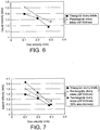
Figure 6 , the results of the experiments with the rectangular slurry inlet with larger widths are compared with the results from the experiments with the triangular slurry inlets (i.e. experiments reported in Example 3).Table 5. Δhtορ (m) Ug (m/s) ul (m/s) 1 0.105 1.51 0.9 0.199 1.36 0.8 0.297 1.26 0.9 0.3 1.27 - As can be seen from
Figure 6 , the downcomer efficiency in the case of the rectangular slurry inlets is no longer lower than with the triangular slurry inlets; in fact it is higher. - The observed behaviour is probably caused by differences in the size of the slurry inlet openings. Assuming spherical gas bubbles, triangular openings with a geometry as used in the Examples will let gas bubbles with diameters less than approximately 50 mm pass unhindered.
- With rectangular openings having dimensions of 29 mm x 220 mm, only gas bubbles with diameters less than 29 mm will pass unhindered, while with rectangular openings with dimensions 49 mm x 220 mm, gas bubbles with diameters less than about 50 mm can pass almost unhindered. Without being bound to any specific theory, it is believed that larger bubbles, which can not pass, for short periods can block the slurry inlets, thereby decreasing the flux through the slurry inlet, and causing lower liquid velocities in the downcomer.
- In this context it can be observed that
WO 98/50494 - The different behaviour for the triangular and the rectangular slurry inlets, where gas bubbles of the same size theoretically can pass unhindered, can, again without being bound to any specific theory, be explained by the flow behaviour in the slurry bubble column reactor. With turbulent flow, each gas bubble has a horizontal and a vertical dynamic velocity component, ug,h and ug,v, respectively.
- With triangular slurry inlets, gas bubbles with a diameter close to 50 mm can only pass unhindered if their vertical velocity component is close to zero. With rectangular inlets, gas bubbles with diameters up to 50 mm can pass unhindered more or less independently of their vertical velocity component.
- In Example 2 it was shown that downcomer efficiency was reduced when the slurry inlet area was reduced. For practical reasons, the slurry inlet area could not be increased with the design described in Example 2. However, there was reason to believe that the efficiency could be increased if the inlet area was increased. With the slurry inlet design described in Example 5, it was possible to increase the slurry inlet area by 50%, by increasing the number of rectangular openings from 6 to 9. In Table 6 below, the results from these experiments are shown. In
Figure 7 , the results from experiments with the rectangular slurry inlet are compared with the results from Example 5.Table 6 Δhtop (m) Ug (m/s) ul (m/s) 1.3 0.107 1.63 1.3 0.199 1.43 1.3 0.297 1.19 - As can be seen from
Figure 7 , by increasing the total slurry inlet area, the liquid velocity in the downcomer was increased. - At high liquid velocities in the downcomer, a vortex is formed and observed in the lower section of the degassing section of the downcomer. This vortex increases the amount of gas in the downcomer tube, thereby decreasing the downcomer efficiency. If the formation of this vortex is hindered, the liquid velocity in the downcomer should increase. To verify this, a vortex break-up device was placed in the conical section between the degassing section and the lower portion of the downcomer tube. Otherwise the same experimental set-up as described in Example 3 was used. In Table 7 below, the results are shown. In
Figure 8 , the results of the experiments with the vortex break-up device are compared with results without this device in use (i.e. experiments reported in Example 3).Table 7 Δhtop (m) ug (m/s) ul (m/s) 1 0.104 1.45 1.1 0.203 1.31 1.1 0.285 1.17 - As can be seen from
Figure 8 , at the lowest gas velocity, with the highest liquid velocity in the downcomer, but only at this low gas velocity, a clear effect of the vortex break-up device can be seen. - A shorter version of the column previously described (6.6 m height), and with a 12.7 cm (5 inch) diameter downcomer generally similar to the downcomer shown in
Figure 1 was filled with water. Air was injected near the bottom of the column, and the superficial gas velocity, ug, and the expanded liquid level above the top of the slurry inlet area, Δhtop, were varied. The results are shown in Table 8 below and inFigure 9 .Table 8 Δhtop (m) Ug (m/s) ul (m/s) 0.1 0.122 0.5 0.11 0.318 0.53 0.17 0.246 0.57 0.6 0.202 0.92 0.69 0.106 1.05 0.82 0.208 1.04 0.94 0.303 0.72 1.07 0.248 1.24 1.6 0.316 1.21 - These results show that the liquid velocity in the downcomer is dependent on the liquid level above the slurry inlet. A certain liquid level is necessary to obtain sufficient liquid velocity in the downcomer. (Since the liquid velocity varies with the liquid level above the slurry inlet, this has been kept approximately constant, and also has been reported in all previous Tables.
Claims (12)
- A slurry bubble column reactor (11) arranged in use to include a slurry phase (12) and, above the slurry phase (12), a gas phase (15), the reactor (11) including a downcomer (16) secured within it, the downcomer (16) comprising an elongate tube, the tube having a lower portion (18) and an upper portion (17), the lower portion (18) having a slurry outlet in the region of the bottom of the tube, the upper portion (17) having a slurry inlet arranged to allow slurry to enter the tube, gas separation means arranged to separate gas bubbles from slurry within the upper portion of the tube and a gas outlet (21) in the region of the top of the tube, the slurry inlet comprising one or more slots (22) in the wall of the upper portion of the tube; in which the uppermost part of the upper portion (17) of the tube extends above the surface of the slurry phase (12) in use and is open for fluid communication with the gas phase (15) above the slurry phase (12), thereby providing the gas outlet (21), and in which the slots (22) in the upper portion of the tube are elongate in the direction of the axis of the downcomer with the height of the slots (22) being greater than their width, and in which the slots are at a position below the surface of the slurry (12) in use.
- A reactor as claimed in Claim 1, in which the gas separation means comprises a separation zone which has a larger cross-sectional area than the lower portion (18) of the tube.
- A reactor as claimed in Claim 2, in which the cross-sectional area of the separation zone is at least a factor of 2 greater than that of the lower portion (18) of the tube.
- A reactor as claimed in any preceding claim, in which the area of the slurry inlet to the downcomer (16) is at least equal to the cross-sectional area of the upper portion (17) of the tube.
- A reactor as claimed in any of Claims 1 to 4, in which the slurry inlet to the downcomer (16) comprises a plurality of rectangular slots (22).
- A reactor as claimed in any of Claims 1 to 4, in which the slurry inlet to the downcomer (16) comprises a plurality of triangular slots.
- A reactor as claimed in any preceding Claim, in which the slots (22) in the downcomer (16) are arranged in a plurality of circumferential rows one above the other, each row extending around the periphery of the downcomer (16).
- A reactor as claimed in any preceding Claim, in which the slots (22) are 0.5 to 20 cm in width at their widest and 2 to 50 cm in height.
- A reactor as claimed in any preceding Claim, in which the vertical length of the downcomer is in the range of 30 - 120% of the intended depth of the slurry (12) in the reactor when in use.
- A reactor as claimed in any preceding Claim, including a plurality of downcomers (16).
- The use of a slurry bubble column reactor (11) as claimed in any preceding Claims, to carry out a Fischer-Tropsch synthesis reaction.
- A method of carrying out a Fischer-Tropsch synthesis reaction which comprises supplying hydrogen gas and carbon monoxide gas to a slurry including a Fischer-Tropsch catalyst in a reactor (11) as claimed in any of Claims 1 to 10.
Applications Claiming Priority (2)
| Application Number | Priority Date | Filing Date | Title |
|---|---|---|---|
| GB0404070A GB2411366B (en) | 2004-02-24 | 2004-02-24 | Downcomers for slurry bubble column reactors |
| PCT/GB2005/000579 WO2005082512A1 (en) | 2004-02-24 | 2005-02-17 | Downcomers for slurry bubble column reactors |
Publications (2)
| Publication Number | Publication Date |
|---|---|
| EP1720645A1 EP1720645A1 (en) | 2006-11-15 |
| EP1720645B1 true EP1720645B1 (en) | 2020-01-22 |
Family
ID=32050771
Family Applications (1)
| Application Number | Title | Priority Date | Filing Date |
|---|---|---|---|
| EP05708381.8A Active EP1720645B1 (en) | 2004-02-24 | 2005-02-17 | Downcomers for slurry bubble column reactors |
Country Status (5)
| Country | Link |
|---|---|
| EP (1) | EP1720645B1 (en) |
| JP (1) | JP5739599B2 (en) |
| KR (1) | KR101095644B1 (en) |
| GB (1) | GB2411366B (en) |
| WO (1) | WO2005082512A1 (en) |
Family Cites Families (8)
| Publication number | Priority date | Publication date | Assignee | Title |
|---|---|---|---|---|
| JPS5740196B2 (en) * | 1973-11-13 | 1982-08-25 | ||
| JPS60147228A (en) * | 1984-01-12 | 1985-08-03 | Mitsubishi Heavy Ind Ltd | Three-phase fluidized reaction apparatus |
| JPS60161739A (en) * | 1984-01-31 | 1985-08-23 | Mitsubishi Heavy Ind Ltd | Three-layered fluidized-bed reactor |
| JPH01119337A (en) * | 1987-11-02 | 1989-05-11 | Mitsubishi Heavy Ind Ltd | Three-phase fluid reaction device |
| JPH03169336A (en) * | 1989-11-24 | 1991-07-23 | Texaco Dev Corp | Recirculating pipe assembled into high pressure reaction vessel |
| US5866621A (en) * | 1997-05-06 | 1999-02-02 | Exxon Research And Engineering Company | Gas and solids reducing slurry downcomer |
| US5962537A (en) * | 1997-05-06 | 1999-10-05 | Exxon Research And Engineering Co | Multizone downcomer for slurry hydrocarbon syntheses process |
| US6570047B1 (en) * | 2001-11-06 | 2003-05-27 | Exxonmobil Research And Engineering Company | Slurry hydrocarbon synthesis with external hydroisomerization in downcomer reactor loop |
-
2004
- 2004-02-24 GB GB0404070A patent/GB2411366B/en not_active Expired - Fee Related
-
2005
- 2005-02-17 KR KR1020067019080A patent/KR101095644B1/en active IP Right Grant
- 2005-02-17 EP EP05708381.8A patent/EP1720645B1/en active Active
- 2005-02-17 JP JP2006553664A patent/JP5739599B2/en not_active Expired - Fee Related
- 2005-02-17 WO PCT/GB2005/000579 patent/WO2005082512A1/en active Application Filing
Non-Patent Citations (1)
| Title |
|---|
| None * |
Also Published As
| Publication number | Publication date |
|---|---|
| KR20070019994A (en) | 2007-02-16 |
| WO2005082512A1 (en) | 2005-09-09 |
| GB0404070D0 (en) | 2004-03-31 |
| GB2411366B (en) | 2008-10-15 |
| KR101095644B1 (en) | 2011-12-19 |
| EP1720645A1 (en) | 2006-11-15 |
| GB2411366A (en) | 2005-08-31 |
| JP2007526825A (en) | 2007-09-20 |
| JP5739599B2 (en) | 2015-06-24 |
Similar Documents
| Publication | Publication Date | Title |
|---|---|---|
| JP5663128B2 (en) | Distributor for two-phase descending parallel flow vessel | |
| US4615870A (en) | Back-mixed hydrotreating reactor | |
| JP2017514687A (en) | Scale collection and pre-distribution tray for vessels with descending two-phase flow | |
| KR101937431B1 (en) | Apparatus and method for hydroconversion | |
| JP2008528248A5 (en) | ||
| JP4203129B2 (en) | Method for producing a liquid product and optionally a gaseous product from a gaseous reactant | |
| AU737425B2 (en) | Throat and cone gas injector and gas distribution grid for slurry reactor | |
| EP0744984B1 (en) | Separation of a suspension into its component parts | |
| SA08290355B1 (en) | Enclosure containing A Granular Bed and A Distribution of A Gas Phase and of A Liquid Phase Circulating in An Ascending Flow in this Enclosure | |
| US5866621A (en) | Gas and solids reducing slurry downcomer | |
| US5688445A (en) | Distributor means and method | |
| EP1720645B1 (en) | Downcomers for slurry bubble column reactors | |
| US6667348B2 (en) | Throat and cone gas injector and gas distribution grid for slurry reactor {CJB-0004} | |
| RU2294954C2 (en) | Reactor for the catalytic cracking with the fluidizated catalyst | |
| CN111790319B (en) | Slurry bed reactor, system and application thereof and Fischer-Tropsch synthesis method | |
| EP1720646A1 (en) | Downcomers for slurry bubble column reactors | |
| US20030021738A1 (en) | Internal device for separating a mixture that comprises at least one gaseous phase and one liquid phase | |
| US6486217B2 (en) | Throat and cone gas injector and gas distribution grid for slurry reactor (CJB-0004) | |
| CN104927893A (en) | Combined catalyst stripper |
Legal Events
| Date | Code | Title | Description |
|---|---|---|---|
| PUAI | Public reference made under article 153(3) epc to a published international application that has entered the european phase |
Free format text: ORIGINAL CODE: 0009012 |
|
| 17P | Request for examination filed |
Effective date: 20060925 |
|
| AK | Designated contracting states |
Kind code of ref document: A1 Designated state(s): AT BE BG CH CY CZ DE DK EE ES FI FR GB GR HU IE IS IT LI LT LU MC NL PL PT RO SE SI SK TR |
|
| R17P | Request for examination filed (corrected) |
Effective date: 20060925 |
|
| RIN1 | Information on inventor provided before grant (corrected) |
Inventor name: MYRSTAD, TROND Inventor name: WIIG, PER, OSCAR Inventor name: SORAKER, PAL Inventor name: JULIUSSEN, OLAV |
|
| DAX | Request for extension of the european patent (deleted) | ||
| 17Q | First examination report despatched |
Effective date: 20090707 |
|
| RAP1 | Party data changed (applicant data changed or rights of an application transferred) |
Owner name: PETROSA Owner name: STATOIL ASA |
|
| STAA | Information on the status of an ep patent application or granted ep patent |
Free format text: STATUS: EXAMINATION IS IN PROGRESS |
|
| GRAP | Despatch of communication of intention to grant a patent |
Free format text: ORIGINAL CODE: EPIDOSNIGR1 |
|
| STAA | Information on the status of an ep patent application or granted ep patent |
Free format text: STATUS: GRANT OF PATENT IS INTENDED |
|
| INTG | Intention to grant announced |
Effective date: 20190801 |
|
| RIN1 | Information on inventor provided before grant (corrected) |
Inventor name: JULIUSSEN, OLAV Inventor name: SORAKER, PAL Inventor name: WIIG, PER, OSCAR Inventor name: MYRSTAD, TROND |
|
| GRAJ | Information related to disapproval of communication of intention to grant by the applicant or resumption of examination proceedings by the epo deleted |
Free format text: ORIGINAL CODE: EPIDOSDIGR1 |
|
| STAA | Information on the status of an ep patent application or granted ep patent |
Free format text: STATUS: EXAMINATION IS IN PROGRESS |
|
| GRAR | Information related to intention to grant a patent recorded |
Free format text: ORIGINAL CODE: EPIDOSNIGR71 |
|
| GRAS | Grant fee paid |
Free format text: ORIGINAL CODE: EPIDOSNIGR3 |
|
| STAA | Information on the status of an ep patent application or granted ep patent |
Free format text: STATUS: GRANT OF PATENT IS INTENDED |
|
| GRAA | (expected) grant |
Free format text: ORIGINAL CODE: 0009210 |
|
| STAA | Information on the status of an ep patent application or granted ep patent |
Free format text: STATUS: THE PATENT HAS BEEN GRANTED |
|
| INTC | Intention to grant announced (deleted) | ||
| AK | Designated contracting states |
Kind code of ref document: B1 Designated state(s): AT BE BG CH CY CZ DE DK EE ES FI FR GB GR HU IE IS IT LI LT LU MC NL PL PT RO SE SI SK TR |
|
| INTG | Intention to grant announced |
Effective date: 20191216 |
|
| REG | Reference to a national code |
Ref country code: GB Ref legal event code: FG4D |
|
| REG | Reference to a national code |
Ref country code: CH Ref legal event code: EP |
|
| REG | Reference to a national code |
Ref country code: AT Ref legal event code: REF Ref document number: 1226567 Country of ref document: AT Kind code of ref document: T Effective date: 20200215 |
|
| REG | Reference to a national code |
Ref country code: IE Ref legal event code: FG4D |
|
| REG | Reference to a national code |
Ref country code: DE Ref legal event code: R096 Ref document number: 602005056586 Country of ref document: DE |
|
| PGFP | Annual fee paid to national office [announced via postgrant information from national office to epo] |
Ref country code: GB Payment date: 20200317 Year of fee payment: 16 |
|
| REG | Reference to a national code |
Ref country code: NL Ref legal event code: MP Effective date: 20200122 |
|
| PGFP | Annual fee paid to national office [announced via postgrant information from national office to epo] |
Ref country code: FR Payment date: 20200320 Year of fee payment: 16 |
|
| REG | Reference to a national code |
Ref country code: LT Ref legal event code: MG4D |
|
| PG25 | Lapsed in a contracting state [announced via postgrant information from national office to epo] |
Ref country code: PT Free format text: LAPSE BECAUSE OF FAILURE TO SUBMIT A TRANSLATION OF THE DESCRIPTION OR TO PAY THE FEE WITHIN THE PRESCRIBED TIME-LIMIT Effective date: 20200614 Ref country code: FI Free format text: LAPSE BECAUSE OF FAILURE TO SUBMIT A TRANSLATION OF THE DESCRIPTION OR TO PAY THE FEE WITHIN THE PRESCRIBED TIME-LIMIT Effective date: 20200122 Ref country code: NL Free format text: LAPSE BECAUSE OF FAILURE TO SUBMIT A TRANSLATION OF THE DESCRIPTION OR TO PAY THE FEE WITHIN THE PRESCRIBED TIME-LIMIT Effective date: 20200122 |
|
| PGFP | Annual fee paid to national office [announced via postgrant information from national office to epo] |
Ref country code: DE Payment date: 20200401 Year of fee payment: 16 |
|
| PG25 | Lapsed in a contracting state [announced via postgrant information from national office to epo] |
Ref country code: BG Free format text: LAPSE BECAUSE OF FAILURE TO SUBMIT A TRANSLATION OF THE DESCRIPTION OR TO PAY THE FEE WITHIN THE PRESCRIBED TIME-LIMIT Effective date: 20200422 Ref country code: SE Free format text: LAPSE BECAUSE OF FAILURE TO SUBMIT A TRANSLATION OF THE DESCRIPTION OR TO PAY THE FEE WITHIN THE PRESCRIBED TIME-LIMIT Effective date: 20200122 Ref country code: GR Free format text: LAPSE BECAUSE OF FAILURE TO SUBMIT A TRANSLATION OF THE DESCRIPTION OR TO PAY THE FEE WITHIN THE PRESCRIBED TIME-LIMIT Effective date: 20200423 Ref country code: IS Free format text: LAPSE BECAUSE OF FAILURE TO SUBMIT A TRANSLATION OF THE DESCRIPTION OR TO PAY THE FEE WITHIN THE PRESCRIBED TIME-LIMIT Effective date: 20200522 |
|
| REG | Reference to a national code |
Ref country code: CH Ref legal event code: PL |
|
| REG | Reference to a national code |
Ref country code: DE Ref legal event code: R097 Ref document number: 602005056586 Country of ref document: DE |
|
| REG | Reference to a national code |
Ref country code: BE Ref legal event code: MM Effective date: 20200229 |
|
| PG25 | Lapsed in a contracting state [announced via postgrant information from national office to epo] |
Ref country code: CZ Free format text: LAPSE BECAUSE OF FAILURE TO SUBMIT A TRANSLATION OF THE DESCRIPTION OR TO PAY THE FEE WITHIN THE PRESCRIBED TIME-LIMIT Effective date: 20200122 Ref country code: RO Free format text: LAPSE BECAUSE OF FAILURE TO SUBMIT A TRANSLATION OF THE DESCRIPTION OR TO PAY THE FEE WITHIN THE PRESCRIBED TIME-LIMIT Effective date: 20200122 Ref country code: SK Free format text: LAPSE BECAUSE OF FAILURE TO SUBMIT A TRANSLATION OF THE DESCRIPTION OR TO PAY THE FEE WITHIN THE PRESCRIBED TIME-LIMIT Effective date: 20200122 Ref country code: MC Free format text: LAPSE BECAUSE OF FAILURE TO SUBMIT A TRANSLATION OF THE DESCRIPTION OR TO PAY THE FEE WITHIN THE PRESCRIBED TIME-LIMIT Effective date: 20200122 Ref country code: DK Free format text: LAPSE BECAUSE OF FAILURE TO SUBMIT A TRANSLATION OF THE DESCRIPTION OR TO PAY THE FEE WITHIN THE PRESCRIBED TIME-LIMIT Effective date: 20200122 Ref country code: LT Free format text: LAPSE BECAUSE OF FAILURE TO SUBMIT A TRANSLATION OF THE DESCRIPTION OR TO PAY THE FEE WITHIN THE PRESCRIBED TIME-LIMIT Effective date: 20200122 Ref country code: EE Free format text: LAPSE BECAUSE OF FAILURE TO SUBMIT A TRANSLATION OF THE DESCRIPTION OR TO PAY THE FEE WITHIN THE PRESCRIBED TIME-LIMIT Effective date: 20200122 Ref country code: LU Free format text: LAPSE BECAUSE OF NON-PAYMENT OF DUE FEES Effective date: 20200217 Ref country code: ES Free format text: LAPSE BECAUSE OF FAILURE TO SUBMIT A TRANSLATION OF THE DESCRIPTION OR TO PAY THE FEE WITHIN THE PRESCRIBED TIME-LIMIT Effective date: 20200122 |
|
| REG | Reference to a national code |
Ref country code: AT Ref legal event code: MK05 Ref document number: 1226567 Country of ref document: AT Kind code of ref document: T Effective date: 20200122 |
|
| PLBE | No opposition filed within time limit |
Free format text: ORIGINAL CODE: 0009261 |
|
| STAA | Information on the status of an ep patent application or granted ep patent |
Free format text: STATUS: NO OPPOSITION FILED WITHIN TIME LIMIT |
|
| PG25 | Lapsed in a contracting state [announced via postgrant information from national office to epo] |
Ref country code: LI Free format text: LAPSE BECAUSE OF NON-PAYMENT OF DUE FEES Effective date: 20200229 Ref country code: CH Free format text: LAPSE BECAUSE OF NON-PAYMENT OF DUE FEES Effective date: 20200229 |
|
| 26N | No opposition filed |
Effective date: 20201023 |
|
| PG25 | Lapsed in a contracting state [announced via postgrant information from national office to epo] |
Ref country code: AT Free format text: LAPSE BECAUSE OF FAILURE TO SUBMIT A TRANSLATION OF THE DESCRIPTION OR TO PAY THE FEE WITHIN THE PRESCRIBED TIME-LIMIT Effective date: 20200122 Ref country code: IT Free format text: LAPSE BECAUSE OF FAILURE TO SUBMIT A TRANSLATION OF THE DESCRIPTION OR TO PAY THE FEE WITHIN THE PRESCRIBED TIME-LIMIT Effective date: 20200122 Ref country code: IE Free format text: LAPSE BECAUSE OF NON-PAYMENT OF DUE FEES Effective date: 20200217 |
|
| PG25 | Lapsed in a contracting state [announced via postgrant information from national office to epo] |
Ref country code: PL Free format text: LAPSE BECAUSE OF FAILURE TO SUBMIT A TRANSLATION OF THE DESCRIPTION OR TO PAY THE FEE WITHIN THE PRESCRIBED TIME-LIMIT Effective date: 20200122 Ref country code: BE Free format text: LAPSE BECAUSE OF NON-PAYMENT OF DUE FEES Effective date: 20200229 Ref country code: SI Free format text: LAPSE BECAUSE OF FAILURE TO SUBMIT A TRANSLATION OF THE DESCRIPTION OR TO PAY THE FEE WITHIN THE PRESCRIBED TIME-LIMIT Effective date: 20200122 |
|
| REG | Reference to a national code |
Ref country code: DE Ref legal event code: R119 Ref document number: 602005056586 Country of ref document: DE |
|
| GBPC | Gb: european patent ceased through non-payment of renewal fee |
Effective date: 20210217 |
|
| PG25 | Lapsed in a contracting state [announced via postgrant information from national office to epo] |
Ref country code: FR Free format text: LAPSE BECAUSE OF NON-PAYMENT OF DUE FEES Effective date: 20210228 Ref country code: GB Free format text: LAPSE BECAUSE OF NON-PAYMENT OF DUE FEES Effective date: 20210217 Ref country code: DE Free format text: LAPSE BECAUSE OF NON-PAYMENT OF DUE FEES Effective date: 20210901 |
|
| PG25 | Lapsed in a contracting state [announced via postgrant information from national office to epo] |
Ref country code: TR Free format text: LAPSE BECAUSE OF FAILURE TO SUBMIT A TRANSLATION OF THE DESCRIPTION OR TO PAY THE FEE WITHIN THE PRESCRIBED TIME-LIMIT Effective date: 20200122 Ref country code: CY Free format text: LAPSE BECAUSE OF FAILURE TO SUBMIT A TRANSLATION OF THE DESCRIPTION OR TO PAY THE FEE WITHIN THE PRESCRIBED TIME-LIMIT Effective date: 20200122 |