EP1720184B1 - Trigger switch - Google Patents
Trigger switch Download PDFInfo
- Publication number
- EP1720184B1 EP1720184B1 EP06008129A EP06008129A EP1720184B1 EP 1720184 B1 EP1720184 B1 EP 1720184B1 EP 06008129 A EP06008129 A EP 06008129A EP 06008129 A EP06008129 A EP 06008129A EP 1720184 B1 EP1720184 B1 EP 1720184B1
- Authority
- EP
- European Patent Office
- Prior art keywords
- operating shaft
- trigger
- contact
- drive member
- contact drive
- Prior art date
- Legal status (The legal status is an assumption and is not a legal conclusion. Google has not performed a legal analysis and makes no representation as to the accuracy of the status listed.)
- Active
Links
Images


Classifications
-
- H—ELECTRICITY
- H01—ELECTRIC ELEMENTS
- H01H—ELECTRIC SWITCHES; RELAYS; SELECTORS; EMERGENCY PROTECTIVE DEVICES
- H01H9/00—Details of switching devices, not covered by groups H01H1/00 - H01H7/00
- H01H9/02—Bases, casings, or covers
- H01H9/06—Casing of switch constituted by a handle serving a purpose other than the actuation of the switch, e.g. by the handle of a vacuum cleaner
- H01H9/063—Casing of switch constituted by a handle serving a purpose other than the actuation of the switch, e.g. by the handle of a vacuum cleaner enclosing a reversing switch
-
- H—ELECTRICITY
- H01—ELECTRIC ELEMENTS
- H01H—ELECTRIC SWITCHES; RELAYS; SELECTORS; EMERGENCY PROTECTIVE DEVICES
- H01H3/00—Mechanisms for operating contacts
- H01H3/32—Driving mechanisms, i.e. for transmitting driving force to the contacts
- H01H3/48—Driving mechanisms, i.e. for transmitting driving force to the contacts using lost-motion device
Landscapes
- Push-Button Switches (AREA)
- Portable Nailing Machines And Staplers (AREA)
Description
- The present invention relates to a trigger switch used for power tools.
- There are widely used trigger switches mounted on a grip of an power tool or the like and enabling the power tool to be started when a user puts a finger thereon to pull in the same.
- As described in
JP-A-10-69838 - However, power tools are frequently handled roughly, and an impact force in a bending direction often acts on an operating shaft to cause a danger that the operating shaft is broken at a base end thereof toward a contact drive part. Therefore, with conventional trigger switches, a contact drive part is formed integral with an operating shaft and a trigger is fixed to the an operating shaft afterward in order to ensure a strength for a base end of the operating shaft, on which an external force is liable to be concentrated. Also, the operating shaft is normally biased in a manner to project outward (toward a trigger). Therefore, when a user pulls a trigger with a finger and quickly separates a finger from the trigger from a state, in which the operating shaft is pushed in, the operating shaft is rapidly moved to cause a fear that the trigger is disengaged by an impact at that time, so that it is also necessary to fix the trigger to the operating shaft firmly.
- Also, since power tools are frequently used in an environment with much dust, trigger switches are demanded to have a dustproof construction, in which dust does not enter inside. Since an operating shaft comes in and out of a trigger switch, an air having a volume equal to that of the operating shaft, which comes in and out, comes in and out of the trigger switch. Such entrance and exit of an air causes a danger of carrying dust into the switch, it is not preferable to make the operating shaft thick, which degrades the dustproof property of a trigger switch. Also, when an operating shaft is made metallic in order to heighten its strength, design becomes difficult since there is a danger of short-circuiting of an electric circuit inside a trigger switch.
- As described above, conventional trigger switches involve a problem that when the dustproof capacity is ensured, an operating shaft is not adequate in strength and in some cases broken by an impact.
- A trigger switch according to the preamble of claim 1 is known from
US 2004/040827 A1 ,US-A-5 084 598 andUS 4698471 . - Hereupon, it is an object of the invention to provide a trigger switch, of which an operating shaft is not broken by an impact force.
- In order to solve the problem, the invention is as defined in claim 1. It provides a trigger switch comprising a stationary contact and a moving contact, which are provided inside a body to be able to come close to and away from each other, a contact drive member accommodated slidably inside the body to drive the moving contact, and an operating shaft having one end thereof engaging with the contact drive member and provided on the other end thereof, which projects from the body, with a trigger, which a user operates, and wherein the operating shaft is put in an engagement state of having play, which enables inclination relative to the contact drive member.
- With such construction, the contact drive member and the operating shaft are separate from each other and play is provided between the both, so that even when an impact is applied to a trigger, it is possible to lessen a bending stress on the operating shaft. Therefore, there does not occur any trouble that the operating shaft is broken.
- Also, with the trigger switch of the invention, the body is protrusively provided with a guide, which guides the trigger in an axial direction, and a maximum angle of inclination of the operating shaft afforded by the play may be made larger than an inclination of the operating shaft allowed by the guide.
- With such construction, the guide bears an external force applied on the trigger and an impact load is not applied to the operating shaft and the contact drive member, so that the operating shaft and the contact drive member are not broken.
- Also, with the trigger switch of the invention, the contact drive member may comprise a wall portion substantially perpendicular to the operating shaft to be provided with a notch, and the operating shaft may be provided with an engagement groove, which engages with the notch.
- With such construction, it is easy to provide play between the operating shaft and the contact drive member. Also, a trigger switch can be assembled by engaging the contact drive member with the operating shaft, which is arranged in a predetermined position, in a direction perpendicular to an axis, and assembly is also made possible by forming a drive shaft and a trigger integrally.
- Also, with the trigger switch of the invention, a maximum angle of inclination afforded by the play may be made not less than 1° but not more than 5°.
- When a maximum angle of inclination afforded by the play is not less than 1°, it is possible to ensure a sufficient play, which eliminates application of an impact to the operating shaft. Also, when a maximum angle of inclination afforded by the play is not more than 5°, a trigger does not suffer from rattling, which makes a user get a sense of incongruity.
- As described above, with the trigger switch of the invention, the contact drive member and the operating shaft are separate from each other and play is provided between the both, so that even when an impact is applied to a trigger, any large force does not act directly on the operating shaft and the operating shaft is not broken. Also, since any large force does not act directly on the operating shaft, it is not necessary to increase a shaft diameter and a trigger switch is realized, which is excellent in dustproof property.
-
-
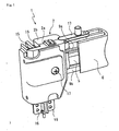
Fig. 1 is a perspective view showing a trigger switch according to an embodiment of the invention; -
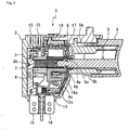
Fig. 2 is an exploded, perspective view showing the trigger switch ofFig. 1 ; -
Fig. 3 is a cross sectional view showing the trigger switch ofFig. 1 ; -
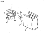
Fig. 4 is an enlarged, perspective view showing a contact drive member and an operating shaft inFig. 1 ; -
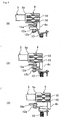
Fig. 5 is a side view showing the relationship between the contact drive member, and moving and stationary contacts inFig. 1 ; and -
Fig. 6 is a cross sectional view showing the contact drive member and the operating shaft inFig. 1 . - An embodiment of the invention will be described below with reference to the drawings.
-
Fig. 1 shows a trigger switch 1 according to an embodiment of the invention, andFigs. 2 and3 are an exploded, perspective view and a cross sectional view showing the trigger switch 1. The trigger switch 1 comprises aswitch assembly 3 accommodated in an internal space of abody 2 composed of aright ccover 2a and aleft cover 2b. Theswitch assembly 3 comprises acontact drive member 4, and thecontact drive member 4 engages with anoperating shaft 5, which extends outside thebody 2. Atrigger 6 is formed at an outer end of theoperating shaft 5 to be made integral with theoperating shaft 5 so that a user put a finger on the trigger to pull theoperating shaft 5 into thebody 2. Thecontact drive member 4 and theoperating shaft 5 are biased by areturn spring 7 in a direction, in which theoperating shaft 5 is pushed outside thebody 2. Arranged on the trigger switch 1 is adustproof ring 8 that seals a gap between theoperating shaft 5 and an opening of thebody 2, through which theoperating shaft 5 extends. Thetrigger 5 is moved alongguides body 2 in an axial direction of theoperating shaft 5. Thecontact drive member 4 is provided, as shown inFig. 5 , with twoslide contacts 10, and axially moved to slide theslide contacts 10 on a surface of aterminal plate 11 and to drive two movingcontacts contact springs 13 to come into pressure contact with or away from twostationary contacts stationary contact 14b is positioned interiorly of thestationary contact 14a and so not shown). Theswitch assembly 3 is positioned in an upper portion of thebody 2 as shown inFig. 3 , and provided withmotor terminals 15, to which feeders to a motor are connected, andpower source terminals 16, which are protruded from the lower portion of themain body 2 and are connected to an electric power source. In theswitch assembly 3, themoving contacts power source terminals 16 and thestationary contacts motor terminals 15, so that themoving contacts stationary contacts motor terminals 15 can be switched in phase by arotary switch 18, which is driven by aswitchover lever 17. Theright cover 2a and theleft cover 2b are fixed by means ofscrews 19. -
Fig. 4 show, in enlarged scale, thecontact drive member 4, theoperating shaft 5, and thetrigger 6, and thecontact drive member 4 and theoperating shaft 5 will be described in detail. Thecontact drive member 4 has awall portion 4a (having a thickness of, for example, 1.0 mm) perpendicular to theoperating shaft 5, thewall portion 4a being provided with aU-shaped notch 4b, which has a smaller width (having a width of, for example, 2.9 mm) than a diameter (having a diameter of, for example, 5.5 mm) of theoperating shaft 5. Also, thecontact drive member 4 is protrusively provided with adrive portion 4c, against which the movingcontacts operating shaft 5 is provided at a barrel portion thereof near an axial end thereof with anengagement groove 5a, which is perpendicular to an axial direction to engage with thenotch 4b, and provided at an end thereof with aseat portion 5b, with which thereturn spring 7 engages. Theengagement groove 5a is formed to be considerably wider (for example, 1.2 mm) than a thickness of thewall portion 4a and to make a thickness of theoperating shaft 5 locally smaller (for example, 2.8 mm) than a width of thenotch 4b. Thewall portion 4a around thenotch 4b of thecontact drive member 4 is fitted into theengagement groove 5a of theoperating shaft 5 whereby theoperating shaft 5 and thecontact drive member 4 are connected to each other with play therebetween to be made movable together in an axial direction. - Subsequently, an operation of the trigger switch 1 will be described.
-
Fig. 5 shows only those constituent elements, which are related to a main operation of the trigger switch, for the convenience of understanding.Fig. 5(A) shows a state, in which a user does not put a finger on thetrigger 6. Theoperating shaft 5 is caused by thereturn spring 7 to project to a maximum extent from thebody 2, and thedrive portion 4c of thecontact drive member 4 pushes down the two movingcontacts contact springs 13 to separate the movingcontacts stationary contacts drive portion 4c has a short portion thereof abutting against the movingcontact 12a on this side in the figure and has a long portion thereof abutting against the movingcontact 12b on the back side in the figure. - As shown in
Fig. 5B , when a user pulls in thetrigger 6 slightly, thecontact drive member 4 moves, so that the movingcontact 12a on this side first disengages from thedrive portion 4c and is caused by thecontact springs 13 to abut against thestationary contact 14a. Thestationary contact 14a, against which the movingcontact 12a abuts, is connected to themotor terminal 15 through a control circuit, which restricts an electric current according to a position of theslide contact 10, and output to the motor is controlled according to an amount, by which thetrigger 6 is pulled in, in a state shown inFig. 5B . - Further, when the
trigger 6 is pulled and the operatingshaft 5 is pushed into the interior of thebody 2, thedrive portion 4c of thecontact drive member 4 also disengages from the movingcontact 12b on the back side in the figure and the movingcontact 12b on the back side abuts against the correspondingstationary contact 14b as shown inFig. 5C . Thestationary contact 14b on the back side (behind 14a) is connected directly to themotor terminal 15 to apply a maximum electric current to the motor. - When a user relaxes a pulling force for the
trigger 6, thecontact drive member 4 and the operatingshaft 5 are pushed back by thereturn spring 7 to go through a state ofFig. 5B to return to a state ofFig. 5A . Thereby, the motor becomes slow in rotation and stops. - Subsequently, an explanation will be given to an effect produced by an engaging structure of the
contact drive member 4 of the trigger switch 1 and the operatingshaft 5.Fig. 6 shows a possible state, in which thecontact drive member 4 and the operatingshaft 5 engage with each other. Since the operatingshaft 5 has play relative to thecontact drive member 4, a maximum inclination of 5° relative to thecontact drive member 4 is possible in an engaged state as shown in the figure. The play between thecontact drive member 4 and the operatingshaft 5 is one obtained by sizing thecontact drive member 4 and the operatingshaft 5 so that they can be formed by an ordinary injection molding and assembled easily. On the other hand, thetrigger 6 is restricted in movement by theguides shaft 5 is limited. Therefore, theguides trigger 6 to thereby enable maintaining an inclination of the operatingshaft 5 at less than 5°. - The trigger switch 1 is designed such that the operating
shaft 5 is thin and thedustproof ring 8 prevents dust and dirt from entering thebody 2. On the other hand, since theguides - Therefore, in the case where an external force in a different direction from a direction, in which the
operating shaft 5 is moved, is tentatively applied to thetrigger 6, the force applied to thetrigger 6 is born by theguides shaft 5 together with thetrigger 6 is inclined relative to thecontact drive member 4 to absorb and relax an external force, so that there is no fear of rupture. - The tentative provision of play such that an inclination of the operating
shaft 5 relative to thecontact drive member 4 exceeds 5° is not preferable since a user gets a sense of incongruity or feels uneasy. Also, while thetrigger 6 is restricted in movement by theguides shaft 5 in the order of 1° in order to enable thetrigger 6 to move smoothly along theguides contact drive member 4 and the operatingshaft 5 is less than 1°, there is a fear that it is not possible to sufficiently absorb and relax an external force applied to thetrigger 6.
Claims (3)
- A trigger switch (1) comprising:a stationary contact (14a, 14b) and a moving contact (12a, 12b), which are provided inside a body (2) to be able to come close to and away from each other,a contact drive member (4) accommodated slidably inside the body (2) to drive the moving contact (12a, 12b), andan operating shaft (5) having a first end being in an engagement state with the contact drive member and a second end, which projects from the body, having a trigger (6) configured to be operated by a user, andwherein the engagement state provides play between the operating shaft (5) and the contact drive member (4), which enables inclination of the operating shaft (5) relative to the contact drive member (4), characterized in thatthe body (2) is protrusively provided with a guide (9a, 9b), which guides the trigger (6) in an axial direction, anda maximum angle of inclination of the operating shaft (5) afforded by the play is larger than an inclination of the operating shaft (5) allowed by the guide.
- The trigger switch according to claim 1, wherein the contact drive member (4) comprises a wall portion (4a) substantially perpendicular to the operating shaft (5) to be provided with a notch (4b), and
the operating shaft (5) is provided with an engagement groove (5a), which engages with the notch (4b). - The trigger switch according to any one of claims 1 to 2, wherein a maximum angle of inclination afforded by the play is not less than 1° but not more than 5°.
Applications Claiming Priority (1)
| Application Number | Priority Date | Filing Date | Title |
|---|---|---|---|
| JP2005134203A JP4696670B2 (en) | 2005-05-02 | 2005-05-02 | Trigger switch |
Publications (3)
| Publication Number | Publication Date |
|---|---|
| EP1720184A2 EP1720184A2 (en) | 2006-11-08 |
| EP1720184A3 EP1720184A3 (en) | 2008-01-23 |
| EP1720184B1 true EP1720184B1 (en) | 2011-06-22 |
Family
ID=36845346
Family Applications (1)
| Application Number | Title | Priority Date | Filing Date |
|---|---|---|---|
| EP06008129A Active EP1720184B1 (en) | 2005-05-02 | 2006-04-19 | Trigger switch |
Country Status (4)
| Country | Link |
|---|---|
| US (1) | US7297891B2 (en) |
| EP (1) | EP1720184B1 (en) |
| JP (1) | JP4696670B2 (en) |
| CN (1) | CN100444296C (en) |
Families Citing this family (20)
| Publication number | Priority date | Publication date | Assignee | Title |
|---|---|---|---|---|
| US7705260B2 (en) * | 2005-04-18 | 2010-04-27 | Xinsheng Xu | Switch assembly |
| JP4941048B2 (en) * | 2007-03-28 | 2012-05-30 | オムロン株式会社 | Trigger switch |
| JP2009199981A (en) * | 2008-02-25 | 2009-09-03 | Satori S-Tech Co Ltd | Switch for electric power tool |
| JP5215890B2 (en) * | 2009-01-28 | 2013-06-19 | 佐鳥エス・テック株式会社 | Trigger switch |
| JP2012028066A (en) * | 2010-07-21 | 2012-02-09 | Satori S-Tech Co Ltd | Trigger switch |
| US20140008090A1 (en) * | 2011-03-31 | 2014-01-09 | Ingersoll-Rand Company | Handheld Power Tools with Triggers and Methods for Assembling Same |
| CN103035436B (en) * | 2011-09-30 | 2015-12-02 | 上海永星电子开关有限公司 | A kind of bipolar single-pole button switch |
| JP5270773B2 (en) * | 2012-02-17 | 2013-08-21 | 佐鳥エス・テック株式会社 | Trigger switch |
| US9559628B2 (en) | 2013-10-25 | 2017-01-31 | Black & Decker Inc. | Handheld power tool with compact AC switch |
| JP6287201B2 (en) * | 2013-12-27 | 2018-03-07 | オムロン株式会社 | Terminal connection structure |
| US10497524B2 (en) * | 2014-03-28 | 2019-12-03 | Black & Decker Inc. | Integrated electronic switch and control module for a power tool |
| DE102014112982A1 (en) * | 2014-09-09 | 2016-03-10 | Johnson Electric Germany GmbH & Co. KG | Electric switch |
| US10637379B2 (en) * | 2015-04-07 | 2020-04-28 | Black & Decker Inc. | Power tool with automatic feathering mode |
| JP2017168268A (en) * | 2016-03-15 | 2017-09-21 | オムロン株式会社 | Trigger switch and electrically-driven tool using the same |
| JP6399066B2 (en) * | 2016-09-27 | 2018-10-03 | オムロン株式会社 | Trigger switch |
| JP2019129045A (en) * | 2018-01-23 | 2019-08-01 | ローランド株式会社 | Switch device and musical sound generation device |
| US20200006021A1 (en) | 2018-06-28 | 2020-01-02 | Black & Decker Inc. | Electronic switch module with oppositely-arranged power switches and discrete heat sinks |
| JP6838012B2 (en) * | 2018-06-29 | 2021-03-03 | 佐鳥電機株式会社 | switch |
| US20220161409A1 (en) * | 2019-01-08 | 2022-05-26 | Shenzhen Topband Co., Ltd. | Electronic device, pcb and electric tool |
| US11345011B2 (en) * | 2020-06-08 | 2022-05-31 | Jenn Feng New Energy Co., Ltd. | Trigger switch device of power tool for preventing accidental triggering |
Family Cites Families (16)
| Publication number | Priority date | Publication date | Assignee | Title |
|---|---|---|---|---|
| US3413498A (en) * | 1965-08-09 | 1968-11-26 | Rockwell Mfg Co | Electrically powered hand tool |
| US3761788A (en) * | 1971-08-10 | 1973-09-25 | Lucerne Products Inc | Electronic switch module with ceramic case |
| DE3342474A1 (en) * | 1983-11-24 | 1985-06-13 | Preh, Elektrofeinmechanische Werke Jakob Preh Nachf. Gmbh & Co, 8740 Bad Neustadt | COUNTER |
| US4565912A (en) * | 1984-05-14 | 1986-01-21 | Eaton Corporation | Trigger switch with rotating contact carrier |
| JPS6142826A (en) * | 1984-08-02 | 1986-03-01 | 松下電器産業株式会社 | Pushbutton unit |
| US4665290A (en) * | 1985-09-30 | 1987-05-12 | Eaton Corporation | Trigger operated portable electric tool switch |
| US4698471A (en) * | 1985-09-30 | 1987-10-06 | Eaton Corporation | Trigger operated portable electric tool switch |
| JPS62100642U (en) * | 1985-12-16 | 1987-06-26 | ||
| US5084598A (en) * | 1987-10-21 | 1992-01-28 | Omron Corporation | Electric switch for a power tool |
| US5198793A (en) * | 1991-07-30 | 1993-03-30 | Eaton Corporation | Electric control apparatus comprising integral electrical conductors plated on a two-shot molded plastic insulating housing |
| US5380971A (en) * | 1992-11-09 | 1995-01-10 | Lucerne Products, Inc. | Dynamic brake switch for motor |
| JP3769873B2 (en) | 1996-06-03 | 2006-04-26 | オムロン株式会社 | Trigger switch |
| CN1207741C (en) * | 2000-01-22 | 2005-06-22 | 马尔夸特有限公司 | Electric switch |
| JP2002367473A (en) * | 2001-06-05 | 2002-12-20 | Fujitsu General Ltd | Key switch for operation panel |
| US6784390B2 (en) * | 2002-08-30 | 2004-08-31 | Defond Manufacturing Limited | Electrical switch |
| US6794594B2 (en) * | 2003-01-13 | 2004-09-21 | Defond Manufacturing Limited | Power tool trigger assembly |
-
2005
- 2005-05-02 JP JP2005134203A patent/JP4696670B2/en not_active Expired - Fee Related
-
2006
- 2006-04-19 EP EP06008129A patent/EP1720184B1/en active Active
- 2006-04-30 CN CNB2006100840404A patent/CN100444296C/en active Active
- 2006-05-02 US US11/416,403 patent/US7297891B2/en active Active
Also Published As
| Publication number | Publication date |
|---|---|
| EP1720184A3 (en) | 2008-01-23 |
| CN100444296C (en) | 2008-12-17 |
| US20060243775A1 (en) | 2006-11-02 |
| JP2006310227A (en) | 2006-11-09 |
| CN1858868A (en) | 2006-11-08 |
| EP1720184A2 (en) | 2006-11-08 |
| US7297891B2 (en) | 2007-11-20 |
| JP4696670B2 (en) | 2011-06-08 |
Similar Documents
| Publication | Publication Date | Title |
|---|---|---|
| EP1720184B1 (en) | Trigger switch | |
| EP2107763A1 (en) | Lock mechanism, slide apparatus, and mobile handset apparatus | |
| KR102229437B1 (en) | Switch contact structure, trigger switch and power tool | |
| JP4605242B2 (en) | Electric tool | |
| CN101463547A (en) | Cover locking device | |
| US11581154B2 (en) | Battery lock out for power tool | |
| JP5884450B2 (en) | Trigger switch | |
| CN107429530B (en) | Handle device for vehicle | |
| CN109305123B (en) | Steering lock device | |
| US10654407B2 (en) | Direction indication mechanism | |
| JPH11277462A (en) | Switch mechanism for power tool | |
| JP6701975B2 (en) | Electric tool | |
| JP4896654B2 (en) | Cable adjustment device | |
| JP2009218064A (en) | Slide operation type electric component | |
| JP4974797B2 (en) | Door strike device | |
| WO2020147002A1 (en) | A power tool with safety linkage mechanism | |
| WO2021171887A1 (en) | Trigger switch and electrical device | |
| US9108308B2 (en) | Switch operation device | |
| JP7473450B2 (en) | Electric tool | |
| JP2001322074A (en) | Dustproof device for toggle switch, and power tool with dustproof device | |
| CN218206258U (en) | Locking device and locking system | |
| WO2021171888A1 (en) | Trigger switch and electric-powered device | |
| CN114649154B (en) | Switch mechanism and electric tool | |
| JP6152314B2 (en) | Vehicle control device | |
| JPH10266663A (en) | Ignition switch |
Legal Events
| Date | Code | Title | Description |
|---|---|---|---|
| PUAI | Public reference made under article 153(3) epc to a published international application that has entered the european phase |
Free format text: ORIGINAL CODE: 0009012 |
|
| AK | Designated contracting states |
Kind code of ref document: A2 Designated state(s): AT BE BG CH CY CZ DE DK EE ES FI FR GB GR HU IE IS IT LI LT LU LV MC NL PL PT RO SE SI SK TR |
|
| AX | Request for extension of the european patent |
Extension state: AL BA HR MK YU |
|
| RIN1 | Information on inventor provided before grant (corrected) |
Inventor name: BABA, YOSHIYUKIC/O OMRON CORPORATION Inventor name: OMORI, KOJIC/O OMRON CORPORATION |
|
| PUAL | Search report despatched |
Free format text: ORIGINAL CODE: 0009013 |
|
| AK | Designated contracting states |
Kind code of ref document: A3 Designated state(s): AT BE BG CH CY CZ DE DK EE ES FI FR GB GR HU IE IS IT LI LT LU LV MC NL PL PT RO SE SI SK TR |
|
| AX | Request for extension of the european patent |
Extension state: AL BA HR MK YU |
|
| 17P | Request for examination filed |
Effective date: 20080609 |
|
| 17Q | First examination report despatched |
Effective date: 20080716 |
|
| AKX | Designation fees paid |
Designated state(s): CH DE FR GB LI |
|
| GRAP | Despatch of communication of intention to grant a patent |
Free format text: ORIGINAL CODE: EPIDOSNIGR1 |
|
| GRAS | Grant fee paid |
Free format text: ORIGINAL CODE: EPIDOSNIGR3 |
|
| GRAA | (expected) grant |
Free format text: ORIGINAL CODE: 0009210 |
|
| AK | Designated contracting states |
Kind code of ref document: B1 Designated state(s): CH DE FR GB LI |
|
| REG | Reference to a national code |
Ref country code: GB Ref legal event code: FG4D |
|
| REG | Reference to a national code |
Ref country code: CH Ref legal event code: EP |
|
| REG | Reference to a national code |
Ref country code: CH Ref legal event code: NV Representative=s name: PATENTANWAELTE SCHAAD, BALASS, MENZL & PARTNER AG |
|
| REG | Reference to a national code |
Ref country code: DE Ref legal event code: R096 Ref document number: 602006022602 Country of ref document: DE Effective date: 20110811 |
|
| PLBE | No opposition filed within time limit |
Free format text: ORIGINAL CODE: 0009261 |
|
| STAA | Information on the status of an ep patent application or granted ep patent |
Free format text: STATUS: NO OPPOSITION FILED WITHIN TIME LIMIT |
|
| 26N | No opposition filed |
Effective date: 20120323 |
|
| REG | Reference to a national code |
Ref country code: DE Ref legal event code: R097 Ref document number: 602006022602 Country of ref document: DE Effective date: 20120323 |
|
| REG | Reference to a national code |
Ref country code: DE Ref legal event code: R082 Ref document number: 602006022602 Country of ref document: DE Representative=s name: KILIAN KILIAN & PARTNER MBB PATENTANWAELTE, DE Ref country code: DE Ref legal event code: R082 Ref document number: 602006022602 Country of ref document: DE Representative=s name: KILIAN KILIAN & PARTNER, DE |
|
| REG | Reference to a national code |
Ref country code: FR Ref legal event code: PLFP Year of fee payment: 11 |
|
| REG | Reference to a national code |
Ref country code: FR Ref legal event code: PLFP Year of fee payment: 12 |
|
| REG | Reference to a national code |
Ref country code: FR Ref legal event code: PLFP Year of fee payment: 13 |
|
| PGFP | Annual fee paid to national office [announced via postgrant information from national office to epo] |
Ref country code: CH Payment date: 20200420 Year of fee payment: 15 |
|
| PG25 | Lapsed in a contracting state [announced via postgrant information from national office to epo] |
Ref country code: CH Free format text: LAPSE BECAUSE OF NON-PAYMENT OF DUE FEES Effective date: 20210430 Ref country code: LI Free format text: LAPSE BECAUSE OF NON-PAYMENT OF DUE FEES Effective date: 20210430 |
|
| PGFP | Annual fee paid to national office [announced via postgrant information from national office to epo] |
Ref country code: FR Payment date: 20230309 Year of fee payment: 18 |
|
| PGFP | Annual fee paid to national office [announced via postgrant information from national office to epo] |
Ref country code: GB Payment date: 20230302 Year of fee payment: 18 |
|
| PGFP | Annual fee paid to national office [announced via postgrant information from national office to epo] |
Ref country code: DE Payment date: 20230228 Year of fee payment: 18 |