JP6152314B2 - Vehicle control device - Google Patents
Vehicle control device Download PDFInfo
- Publication number
- JP6152314B2 JP6152314B2 JP2013158585A JP2013158585A JP6152314B2 JP 6152314 B2 JP6152314 B2 JP 6152314B2 JP 2013158585 A JP2013158585 A JP 2013158585A JP 2013158585 A JP2013158585 A JP 2013158585A JP 6152314 B2 JP6152314 B2 JP 6152314B2
- Authority
- JP
- Japan
- Prior art keywords
- cancel
- intermediate member
- operation lever
- force
- driving body
- Prior art date
- Legal status (The legal status is an assumption and is not a legal conclusion. Google has not performed a legal analysis and makes no representation as to the accuracy of the status listed.)
- Expired - Fee Related
Links
Images


Classifications
-
- B—PERFORMING OPERATIONS; TRANSPORTING
- B60—VEHICLES IN GENERAL
- B60Q—ARRANGEMENT OF SIGNALLING OR LIGHTING DEVICES, THE MOUNTING OR SUPPORTING THEREOF OR CIRCUITS THEREFOR, FOR VEHICLES IN GENERAL
- B60Q1/00—Arrangement of optical signalling or lighting devices, the mounting or supporting thereof or circuits therefor
- B60Q1/26—Arrangement of optical signalling or lighting devices, the mounting or supporting thereof or circuits therefor the devices being primarily intended to indicate the vehicle, or parts thereof, or to give signals, to other traffic
- B60Q1/34—Arrangement of optical signalling or lighting devices, the mounting or supporting thereof or circuits therefor the devices being primarily intended to indicate the vehicle, or parts thereof, or to give signals, to other traffic for indicating change of drive direction
- B60Q1/40—Arrangement of optical signalling or lighting devices, the mounting or supporting thereof or circuits therefor the devices being primarily intended to indicate the vehicle, or parts thereof, or to give signals, to other traffic for indicating change of drive direction having mechanical, electric or electronic automatic return to inoperative position
- B60Q1/42—Arrangement of optical signalling or lighting devices, the mounting or supporting thereof or circuits therefor the devices being primarily intended to indicate the vehicle, or parts thereof, or to give signals, to other traffic for indicating change of drive direction having mechanical, electric or electronic automatic return to inoperative position having mechanical automatic return to inoperative position due to steering-wheel position, e.g. with roller wheel control
- B60Q1/425—Arrangement of optical signalling or lighting devices, the mounting or supporting thereof or circuits therefor the devices being primarily intended to indicate the vehicle, or parts thereof, or to give signals, to other traffic for indicating change of drive direction having mechanical, electric or electronic automatic return to inoperative position having mechanical automatic return to inoperative position due to steering-wheel position, e.g. with roller wheel control using a latching element for resetting a switching element
-
- G—PHYSICS
- G05—CONTROLLING; REGULATING
- G05G—CONTROL DEVICES OR SYSTEMS INSOFAR AS CHARACTERISED BY MECHANICAL FEATURES ONLY
- G05G5/00—Means for preventing, limiting or returning the movements of parts of a control mechanism, e.g. locking controlling member
- G05G5/05—Means for returning or tending to return controlling members to an inoperative or neutral position, e.g. by providing return springs or resilient end-stops
-
- G—PHYSICS
- G05—CONTROLLING; REGULATING
- G05G—CONTROL DEVICES OR SYSTEMS INSOFAR AS CHARACTERISED BY MECHANICAL FEATURES ONLY
- G05G5/00—Means for preventing, limiting or returning the movements of parts of a control mechanism, e.g. locking controlling member
- G05G5/06—Means for preventing, limiting or returning the movements of parts of a control mechanism, e.g. locking controlling member for holding members in one or a limited number of definite positions only
-
- G—PHYSICS
- G05—CONTROLLING; REGULATING
- G05G—CONTROL DEVICES OR SYSTEMS INSOFAR AS CHARACTERISED BY MECHANICAL FEATURES ONLY
- G05G1/00—Controlling members, e.g. knobs or handles; Assemblies or arrangements thereof; Indicating position of controlling members
- G05G1/04—Controlling members for hand actuation by pivoting movement, e.g. levers
-
- Y—GENERAL TAGGING OF NEW TECHNOLOGICAL DEVELOPMENTS; GENERAL TAGGING OF CROSS-SECTIONAL TECHNOLOGIES SPANNING OVER SEVERAL SECTIONS OF THE IPC; TECHNICAL SUBJECTS COVERED BY FORMER USPC CROSS-REFERENCE ART COLLECTIONS [XRACs] AND DIGESTS
- Y10—TECHNICAL SUBJECTS COVERED BY FORMER USPC
- Y10T—TECHNICAL SUBJECTS COVERED BY FORMER US CLASSIFICATION
- Y10T74/00—Machine element or mechanism
- Y10T74/20—Control lever and linkage systems
- Y10T74/20396—Hand operated
Landscapes
- Engineering & Computer Science (AREA)
- Physics & Mathematics (AREA)
- General Physics & Mathematics (AREA)
- Automation & Control Theory (AREA)
- Mechanical Engineering (AREA)
- Lighting Device Outwards From Vehicle And Optical Signal (AREA)
- Mechanisms For Operating Contacts (AREA)
Description
本発明は、操作レバーを回動させる操作によってターンシグナルスイッチなどを動作させる車両用操作装置に関する。 The present invention relates to a vehicle operation device that operates a turn signal switch or the like by an operation of rotating an operation lever.
特許文献1にターンシグナルスイッチ装置に関する発明が開示されている。
この装置は、操作レバーと一体の保持体がハウジングに回動自在に支持されている。ハウジングにカム部材が設けられ、操作レバーの基部から突出する駆動ピンがカム部材に圧接されている。このカムの形状によって、操作レバーが中立姿勢に向けて復帰できるように付勢されているとともに、操作レバーを中立姿勢から両側へ回動させて操作姿勢に設定したときに、操作レバーが仮固定される。 In this apparatus, a holding body integral with an operation lever is rotatably supported by a housing. A cam member is provided in the housing, and a drive pin protruding from the base of the operation lever is pressed against the cam member. This cam shape biases the operating lever so that it can return toward the neutral position, and when the operating lever is turned from the neutral position to both sides and set to the operating position, the operating lever is temporarily fixed. Is done.
前記ハウジングに、キャンセルレバーが設けられ、保持体の下側に設けられた圧縮コイルばねによって前記キャンセルレバーがハウジングから突出する方向へ付勢されている。 A cancel lever is provided in the housing, and the cancel lever is biased in a direction protruding from the housing by a compression coil spring provided on the lower side of the holding body.
車両走行時に操作レバーをいずれかの操作姿勢へ回動させて仮固定させると、前記圧縮コイルばねの付勢力でキャンセルレバーが突出方向へ移動させられ、キャンセルレバーと一体の突出部がハウジングから突出させられる。ステアリングホイールをターン方向へ回転させた後に復帰方向へ逆回転させると、ステアリングホイールとともに回転するキャンセル突起が前記突出部に当たり、キャンセルレバーが回動させられる。キャンセルレバーの回動力によって操作レバーに中立姿勢への復帰力が与えられ、この復帰力によって操作姿勢での仮固定が解除されて、操作レバーが中立姿勢へ復帰させられる。 When the operating lever is rotated to any operating position and temporarily fixed while the vehicle is running, the canceling lever is moved in the protruding direction by the urging force of the compression coil spring, and the protruding portion integrated with the canceling lever protrudes from the housing. Be made. When the steering wheel is rotated in the turn direction and then reversely rotated in the return direction, the cancel protrusion that rotates together with the steering wheel hits the protrusion, and the cancel lever is rotated. The return force to the neutral posture is given to the operation lever by the turning force of the cancel lever, and the temporary fixing in the operation posture is released by this return force, and the operation lever is returned to the neutral posture.
また、操作姿勢へ移動した操作レバーを手などで拘束した状態で、ステアリングとともに回転するキャンセル突起によってキャンセルレバーに回動力が与えられると、保持体に設けられた駆動体がばねの力に抗して後退させられて、キャンセルレバーなどに過度な外力が作用しないように構成されている。 In addition, when the operating lever moved to the operating posture is restrained by a hand or the like, if the canceling lever that rotates with the steering gives rotation force to the canceling lever, the driving body provided on the holding body resists the force of the spring. So that an excessive external force does not act on the cancel lever or the like.
特許文献1に記載されたターンシグナルスイッチ装置は、キャンセルレバーが圧縮コイルばねの力によって突出方向へ付勢されており、この圧縮コイルばねが、キャンセルレバーの上方で且つ操作レバーの下側のスペースに配置されている。圧縮コイルの配置スペースが必要であるため、機構の配置高さ寸法が大きく必要となり、薄型化が困難である。
In the turn signal switch device described in
前記圧縮コイルばねによってキャンセルレバーに対して突出方向への付勢力が与えられるとともに、回動したキャンセルレバーに対して前記圧縮コイルばねから回動方向の中立位置への復帰力が与えられる。しかし、圧縮コイルばねからキャンセルレバーに与えられる回動付勢力が弱いため、回動復帰力を確保するために、圧縮ばねとして必要以上にばね定数の高いものを使用することが必要になる。その結果、キャンセルレバーを後退させる際の駆動負荷が過大になる問題が生じる。 A biasing force in the protruding direction is applied to the cancel lever by the compression coil spring, and a return force from the compression coil spring to the neutral position in the rotation direction is applied to the rotated cancel lever. However, since the rotation biasing force applied from the compression coil spring to the cancel lever is weak, it is necessary to use a compression spring having a higher spring constant than necessary in order to ensure the rotation return force. As a result, there arises a problem that the driving load is excessive when the cancel lever is moved backward.
特許文献1に記載された装置では、操作レバーと共に回動する保持体よりも前方の位置にキャンセルレバーが配置されているため、保持体とステアリングのキャンセル突起との間にキャンセルレバーの配置ならびに動作領域を広く確保しなくてならず、装置の小型化が難しくなる。
In the apparatus described in
本発明は上記従来の課題を解決するものであり、装置の薄型化と小型化を実現でき、且つ撓みばね部材を使用することで、キャンセル駆動体の突出方向と回動復帰方向への付勢力を効果的に与えることができる車両用操作装置を提供することを目的としている。 SUMMARY OF THE INVENTION The present invention solves the above-described conventional problems, and can reduce the thickness and size of the apparatus, and uses a bending spring member, thereby biasing the canceling drive body in the protruding direction and the rotational return direction. It is an object of the present invention to provide a vehicular operating device that can effectively provide the above.
本発明は、中立姿勢から2つの操作姿勢に向けて相反する2方向へ回動可能な操作レバーと、前記操作レバーと共に回動する回動体と、前記操作レバーを中立姿勢へ復帰させる付勢力を与える復帰付勢機構と、それぞれの操作姿勢まで回動した前記操作レバーを仮固定する仮固定機構とが設けられた車両用操作装置において、
固定側ガイドによって後退位置と突出位置との間で移動自在に案内され、突出位置へ移動したときに外部から2方向へのキャンセル力を受けて回動するキャンセル駆動体と、
基部が固定され、前記回動体の回動軸と垂直な平面内に延びて、前記キャンセル駆動体を突出位置に向けて付勢する撓みばね部材と、
前記回動体と前記キャンセル駆動体のいずれかに設けられて、前記操作レバーが中立姿勢のときに前記キャンセル駆動体を後退位置に移動させ、前記操作レバーが操作姿勢へ回動したときにキャンセル駆動体を突出位置へ移動させる進退制御カムと、
キャンセル力を受けた前記キャンセル駆動体が回動したときにその回動力を受ける中間部材と、
前記中間部材と前記回動体との間に設けられて、前記キャンセル駆動体から前記中間部材に与えられた回動力を前記操作レバーに伝達するとともに、前記操作レバーが拘束された状態で前記キャンセル駆動体から前記中間部材に回動力が与えられたときに前記回動体と前記中間部材とを相対的に移動させる伝達案内部と、
前記中間部材と前記回動体との間に設けられて、前記中間部材を、その回動力を前記回動体に伝達できる初期姿勢へ付勢する弾性部材と、が設けられており、
前記キャンセル駆動体に、前記キャンセル駆動体の回転中心を挟む両側に位置して前記撓みばね部材の弾圧力を受ける2つの付勢当接部が設けられて、それぞれの前記付勢当接部と前記キャンセル駆動体の回転中心は、前記キャンセル駆動体の突出移動方向と交差する方向に間隔を空けて配置されており、
前記撓みばね部材の自由端部に前記突出移動方向に向かって突出した屈曲部が形成され、前記屈曲部を挟んだ両側部分が、突出位置へ移動した前記キャンセル駆動体の2つの前記付勢当接部にそれぞれ当接した状態で、前記屈曲部が、2つの前記付勢当接部の間に形成された凹状の空間に位置することを特徴とする
ものである。
The present invention provides an operation lever that can be rotated in two opposite directions from a neutral posture toward two operation postures, a rotating body that rotates together with the operation lever, and a biasing force that returns the operation lever to a neutral posture. In the vehicular operating device provided with a return biasing mechanism for providing and a temporary fixing mechanism for temporarily fixing the operation lever rotated to the respective operation postures,
A cancel driver that is guided by a fixed guide so as to be movable between a retracted position and a protruding position, and that rotates by receiving a canceling force in two directions from the outside when moving to the protruding position;
A flexible spring member that has a base fixed, extends in a plane perpendicular to the rotation axis of the rotating body, and biases the cancel driving body toward the protruding position;
Provided in either the rotating body or the cancellation driving body, the cancel driving body is moved to the retracted position when the operation lever is in the neutral position, and the cancel drive is performed when the operation lever is rotated to the operation position. An advancing and retracting control cam that moves the body to the protruding position;
An intermediate member that receives the turning force when the cancel driving body that receives the canceling force rotates,
The cancel drive is provided between the intermediate member and the rotating body and transmits the rotational force applied to the intermediate member from the cancel drive body to the operation lever and the operation lever is restrained. A transmission guide for relatively moving the rotating body and the intermediate member when rotational force is applied from the body to the intermediate member;
An elastic member provided between the intermediate member and the rotating body and biasing the intermediate member to an initial posture capable of transmitting the turning force to the rotating body ;
The cancel drive body is provided with two bias contact portions that are located on both sides of the rotation center of the cancel drive body and receive the elastic force of the flexible spring member, and each of the bias contact portions and The center of rotation of the cancel driving body is arranged at an interval in a direction intersecting the protruding movement direction of the cancel driving body,
A bent portion that protrudes in the protruding movement direction is formed at the free end portion of the bending spring member, and the two biasing portions of the cancel drive member that have moved to the protruding position are located on both sides of the bent portion. The bent portion is located in a concave space formed between the two urging contact portions in a state of being in contact with each contact portion .
本発明の車両用操作装置は、撓みばね部材が回動体の回動軸と垂直な平面内に延びているため、ばね部材を配置するための上下のスペースを薄くでき、装置の薄型化に寄与できるようになる。 In the vehicle operating device according to the present invention, since the flexible spring member extends in a plane perpendicular to the rotating shaft of the rotating body, the upper and lower spaces for arranging the spring member can be thinned, contributing to the thinning of the device. become able to.
本発明の車両用操作装置では、キャンセル駆動体の回転中心から離れた位置に付勢当接部が設けられて、撓みばね部材が付勢当接部に当接してので、撓みばね部材からキャンセル駆動体に対して突出方向への付勢力のみならず、回動復帰方向への付勢力を効果的に与えることができる。 In the vehicle operating device according to the present invention, the biasing contact portion is provided at a position away from the rotation center of the cancel drive body, and the bending spring member is in contact with the biasing contact portion. Not only the urging force in the protruding direction but also the urging force in the rotation return direction can be effectively applied to the drive body.
本発明は、前記キャンセル駆動体には、前記平面と直交する方向である厚さ方向の中間に溝が形成されており、前記撓みばね部材が前記溝内に入り込んで、前記付勢当接部と当接しているものが好ましい。 In the present invention, the cancel driving body has a groove formed in the middle of the thickness direction which is a direction orthogonal to the plane, and the bending spring member enters the groove, and the biasing contact portion Those that are in contact with are preferable.
上記構成では、撓みばね部材がキャンセル駆動体の高さ寸法の範囲内で延び出ているため、装置全体の薄型化を実現できる。 In the above configuration, since the bending spring member extends within the range of the height dimension of the cancel drive body, it is possible to reduce the thickness of the entire apparatus.
本発明は、前記進退制御カムは、前記回動体に形成されて回動軸側に向けて突形状であり、前記キャンセル駆動体に設けられた従動部が、前記回動軸側から前記進退制御カムと当接するものとして構成できる。 In the present invention, the advance / retreat control cam is formed on the rotating body and has a projecting shape toward the rotating shaft side, and a follower provided on the cancel driving body is controlled to advance / retreat from the rotating shaft side. It can comprise as what contacts a cam.
上記構成では、回動体の回動軸と進退制御カムとの間にキャンセル駆動体の従動部が配置されているため、キャンセル駆動体が移動する前後方向での装置の寸法を短くでき、車両用操作装置の小型化を実現できる。 In the above configuration, since the driven portion of the cancel driving body is disposed between the rotating shaft of the rotating body and the advance / retreat control cam, the dimensions of the device in the front-rear direction in which the cancel driving body moves can be shortened. Miniaturization of the operating device can be realized.
本発明は、前記伝達案内部では、前記回動体と前記中間部材の一方に摺動突起が他方に摺動カムが形成されて、前記摺動突起が前記摺動カムに摺動自在に案内されており、
前記キャンセル駆動体から回動力を受けていない初期状態の前記中間部材は、前記弾性部材の付勢力で前記キャンセル駆動体の突出方向へ向けて押し付けられ、前記中間部材に与えられた回動力によって前記中間部材と前記回動体とが一緒に回動自在となり、
前記操作レバーが拘束された状態で前記キャンセル駆動体から前記中間部材に回動力が与えられると、前記摺動突起と前記摺動カムとが摺動して、前記中間部材が突出方向と逆の方向へ回動しながら後退させられるものである。
According to the present invention, in the transmission guide portion, a sliding projection is formed on one of the rotating body and the intermediate member, and a sliding cam is formed on the other, and the sliding projection is slidably guided by the sliding cam. And
The intermediate member in an initial state not receiving the turning force from the cancel driving body is pressed toward the protruding direction of the cancel driving body by the urging force of the elastic member, and the turning force given to the intermediate member The intermediate member and the rotating body can be rotated together,
When turning force is applied to the intermediate member from the cancel driving body in a state where the operation lever is restrained, the sliding protrusion and the sliding cam slide, and the intermediate member is opposite to the protruding direction. It is retracted while rotating in the direction.
操作レバーが拘束されたときに、中間部材が回動しながら後退することで、キャンセル駆動体にキャンセル力が与えられたときに、キャンセル駆動体の回動力を容易に吸収でき、各部品に過大な抵抗負荷が作用するのを防止できる。 When the operating lever is restrained, the intermediate member moves backward while rotating, so that when the canceling drive is given a canceling force, the rotating force of the canceling drive can be easily absorbed, and each component is excessive. It is possible to prevent various resistive loads from acting.
本発明は、キャンセル駆動体を撓みばね部材で付勢することで、機構が積み重なる高さ方向の寸法を低くでき、薄型化に貢献できるようになる。また撓みばね部材を使用することで、キャンセル駆動体に対して突出方向への付勢力と回動復帰方向への付勢力を効果的に与えることが可能である。 According to the present invention, by urging the cancel drive body with the bending spring member, the height dimension in which the mechanisms are stacked can be reduced, and the thickness can be reduced. Further, by using the bending spring member, it is possible to effectively give the urging force in the protruding direction and the urging force in the rotation return direction to the canceling drive body.
本発明の実施の形態の車両用操作装置は、自動車のステアリング軸の側方に設けられて、ターンシグナルの切り替えを行うために使用される。 A vehicle operating device according to an embodiment of the present invention is provided on a side of a steering shaft of an automobile and is used for switching a turn signal.
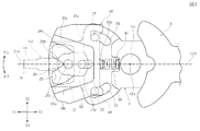
図1に示すように、車両用操作装置は、固定部として機能する下部筐体1と上部筐体2を有している。図2と図3に示すように、操作レバー3の基部に回動体4が取り付けられている。操作レバー3の基部にはX方向の両側に突出する連結軸3aが一体に形成されて、回動体4にはX方向に貫通する連結穴4eが形成され、それぞれの連結軸3aが連結穴4eに挿入されている。図2に示すように、回動体4に対して操作レバー3がα方向(X軸回り)へわずかに回動でき、β方向(Z軸回り)では回動体4と操作レバー3とが一体化されて相対的に回動できないように連結されている。
As shown in FIG. 1, the vehicular operating device has a
図1と図2に示すように、回動体4には、上方へ一体に突出する上部支持軸4aと、下方へ一体に突出する下部支持軸4bが一体に形成されている。上部支持軸4aの中心と下部支持軸4bの中心は、上下方向(Z方向)に延びる回動軸O1上に一致している。下部筐体1に下部軸受け部1aが形成され、上部筐体2に上部軸受け部2aが形成されている。下部支持軸4bが下部軸受け部1aに回動自在に支持され、上部支持軸4aが上部軸受け部2aに回動自在に支持されている。その結果、操作レバー3と回動体4は、回動軸O1を中心としてβ方向へ一体となって回動することができる。
As shown in FIGS. 1 and 2, the rotating body 4 is integrally formed with an
図1と図3に示すように、操作レバー3の基部に保持穴3bが形成されており、この保持穴3b内に、復帰ピン5が収納されている。復帰ピン5の先端摺動部5aは操作レバー3の保持穴3b内から前方(Y1方向)へ突出している。復帰ピン5にフランジ部5bが一体に形成されている。復帰ピン5の外周に、圧縮コイルばねの復帰ばね6が装着されて、復帰ばね6が、保持穴3bの後方(Y2方向)の底部とフランジ部5bとの間に圧縮させられて介在している。この復帰ばね6によって、復帰ピン5が前方(Y1方向)へ向けて付勢されている。
As shown in FIGS. 1 and 3, a holding
図1と図3に示すように、復帰ピン5の軸中心を通過する線が、操作レバー3の回動基準線O2である。
As shown in FIGS. 1 and 3, the line passing through the center of the return pin 5 is the rotation reference line O <b> 2 of the
図1と図3に示すように、下部筐体1の内部前方に復帰カム部材7が固定されており、復帰カム部材7のカム面8に復帰ピン5が押し付けられている。復帰ピン5と復帰ばね6と復帰カム部材7とで、復帰付勢機構と仮固定機構とが構成されている。
As shown in FIGS. 1 and 3, the
図1に示すように、復帰カム部材7をY−Z平面と平行な断面で切断したときのカム面8の形状は、復帰基準部8aと、復帰基準部8aに対してα方向の両側に形成された復帰傾斜部8b,8bを有している。操作レバー3が連結軸3aを支点としてα方向へ回動したときは、復帰ピン5の先端摺動部5aが復帰傾斜部8b,8bに乗り上がり、復帰ばね6の復帰付勢力で、先端摺動部5aが復帰基準部8aと嵌合するように常に復帰させられる。
As shown in FIG. 1, when the
図3に、復帰カム部材7を、前記復帰基準部8aの位置でX−Y平面と平行な断面で切断したときのカム面8の形状が示されている。カム面8には、X方向の中心部に中立復帰部8cが形成され、中立復帰部8cのβ方向の両側に復帰傾斜部8d,8dが形成されている。β1側の復帰傾斜部8dのさらにβ1側に仮固定部8eが形成され、β2側の復帰規制部8dのさらにβ2側に仮固定部8fが形成されている。2か所の仮固定部8e,8fは凹状に形成されている。
FIG. 3 shows the shape of the
中立復帰部8cと復帰傾斜部8d,8dおよび復帰ピン5と復帰ばね6によって復帰付勢機構が構成されている。この復帰付勢機構によって、操作レバー3は、復帰ピン5の先端摺動部5aが中立復帰部8cと嵌合する中立姿勢(回動基準線O2がY方向に向けられる中立姿勢)に向けて付勢されている。
The
前記仮固定部8e,8fおよび復帰ピン5と復帰ばね6によって仮固定機構が構成されている。この仮固定機構では、復帰ピン5の先端摺動部5aが仮固定部8e,8fに嵌合する操作姿勢で、操作レバー3が仮固定される。図3では、操作レバー3と回動体4がβ1方向へ回動したときの復帰ピン5が破線で示されている。この状態では、復帰ピン5の先端摺動部5aが仮固定部8eに嵌合し、操作レバー1が第1の操作姿勢に至って仮固定されている。
The
逆に、操作レバー3が中立姿勢からβ2方向へ回動させられると、復帰ピン5の先端摺動部5aが仮固定部8fに嵌合し、操作レバー3が第2の操作姿勢に至って仮固定される。
Conversely, when the operating
回動体4の上方にキャンセル駆動体10が設けられている。図1と図2に示すように、キャンセル駆動体10は、本体部11を有している。本体部11の上方には支持軸12が一体に形成されている。図1と図2に示すように、上部筐体2の天井部には、Y1−Y2方向に直線的に延びる固定側ガイド2bが形成されており、前記支持軸12が固定側ガイド2bに摺動自在で且つ回動自在に支持されている。支持軸12の中心線O3が、キャンセル駆動体10を前後方向(Y1−Y2)へ移動させる移動基準線であり、且つキャンセル駆動体10をX−Y平面内で回動させる回転中心である。
A cancel driving
本体部11の前方(Y1方向)に向く先端部は突出部18である。図1に示すように、上部筐体2の前方に突出口2cが開口しており、キャンセル駆動体10が固定側ガイド2bに案内されて前方(Y1方向)へ移動すると、突出部18が突出口2cから上部筐体2の前方へ突出させられる。
The front end of the
図1に示すように、キャンセル駆動体10の本体部11の下部には、従動部13が下向きに一体に形成されている。
As shown in FIG. 1, a driven
図1と図2では、支持軸12と従動部13を除いた本体部11の上下方向の厚さ寸法がHで示されている。図1に示すように、本体部11の厚さ方向の中間部分に、後方(Y2方向)に向けて解放された溝14が形成されている。本体部11は、溝14よりも下側がキャンセルカム部15であり、溝14よりも上側が上体部16である。溝14の内部では、前記上体部16の下面に連続する付勢カム部17が一体に形成されている。
1 and 2, the thickness dimension in the vertical direction of the
図8と図9には、キャンセル駆動体10が溝14の内部を通過するX−Y平面と平行な平面で切断された断面図が示されている。
8 and 9 are cross-sectional views in which the cancel
キャンセル駆動体10のキャンセルカム部15は、後方(Y2側)で且つX2側に位置する角部が第1の押圧部15aであり、後方で且つX1側に位置する角部が第2の押圧部15bである。
The cancel
図8には、キャンセル駆動体10の支持軸12の中心線O3が固定側ガイド2bに沿って前後方向(Y1−Y2方向)へ直線的に移動するときの突出移動基準線O4が示されている。図8に示すように、本体部11の突出部18が突出移動基準線O4と平行に向けられているとき、第1の押圧部15aと第2の押圧部15bは、突出移動基準線O4を挟んでX方向の両側に等距離離れて位置している。すなわち、第1の押圧部15aと第2の押圧部15bは、中心線O3を挟んで、キャンセル駆動体10の移動方向に対してX1側とX2側の両側に配置されている。
FIG. 8 shows a protrusion movement reference line O4 when the center line O3 of the
図8と図9に示すように、溝14の内部に形成されている付勢カム部17では、X1側において後方(Y2方向)に向けて突出する第1の付勢当接部17aと、X2側において後方に向けて突出する第2の付勢当接部17bとが形成されている。
As shown in FIGS. 8 and 9, the biasing
図8に示すように、本体部11の突出部18が突出移動基準線O4と平行に向けられているとき、第1の付勢当接部17aと第2の付勢当接部17bは、突出移動基準線O4を挟んでX方向の両側に等距離離れて位置している。すなわち、第1の付勢当接部17aと第2の付勢当接部17bは、中心線O3を挟んで、キャンセル駆動体10の移動方向に対してX1側とX2側の両側に配置されている。
As shown in FIG. 8, when the projecting
図8に示すように、下部筐体1内にトーションスプリング20が設けられている。トーションスプリング20の巻き部21は、固定部である下部筐体1に設けられた固定突起1bに装着されている。トーションスプリング20の巻き部21から延び出る一方の弾性線が撓みばね部材22である。巻き部21から他方に延びる弾性線23は、下部筐体1の内壁部1cに突き当てられている。
As shown in FIG. 8, a
撓みばね部材22は、X−Y平面内に延び出ている。すなわち、撓みばね部材22は、キャンセル駆動体10の溝14を通過し、回転軸O1や中心線O3と垂直に延びる平面に沿って延び出ている。
The bending
自由状態の撓みばね部材22は、図8と図9に示すγ1方向へ大きく傾けられており、撓みばね部材22にγ2方向への撓み(曲げ変形)を与えると、γ1方向へ向けた反発弾性力が発揮される。
The
撓みばね部材22の自由端部は、キャンセル駆動体10の溝14の内部に入り込んでいる。図8と図9に示すように、撓みばね部材22の自由端部には曲げ部22aが設けられ、この曲げ部22aを挟んで基部側の弾圧部22bと先部側の弾圧部22cが形成されている。基部側の弾圧部22bは曲げ部22aを起点としてX1方向に向かうにしたがって後方(Y2方向)へ斜めに延びている。先部側の弾圧部22cも、曲げ部22aを起点として、X2方向かうにしたがって後方(Y2方向)へ斜めに延びている。
The free end portion of the bending
撓みばね部材22は、キャンセル駆動体10に設けられた第1の付勢当接部17aと第2の付勢当接部17bの少なくとも一方に当接する。図8に示すように、撓みばね部材22によって、キャンセル駆動体10は突出方向(Y1方向)へ付勢される。
The bending
図8では、後方(Y2方向)に移動して後退位置(a)となったキャンセル駆動体10が実線で示され、前方(Y1方向)へ移動して突出位置(b)となったキャンセル駆動体10が破線で示されている。キャンセル駆動体10が突出位置(b)に移動すると、キャンセル駆動体10の突出部18が、上部筐体2から前方(Y1方向)へ大きく突出する。
In FIG. 8, the cancel driving
図8に示すように、キャンセル駆動体10が突出位置(b)へ移動すると、撓みばね部材22の基部側の弾圧部22bが第1の付勢当接部17aに当接し、先部側の弾圧部22cが第2の付勢当接部17bに当接する。第1の付勢当接部17aと第2の付勢当接部17bの双方が、撓みばね部材22からの弾性押圧力を受けるため、突出位置(b)のキャンセル駆動体10は、突出部18が突出移動基準線O4と平行に延びた姿勢で安定状態となる。
As shown in FIG. 8, when the cancel driving
図9には、突出位置(b)に至ったキャンセル駆動体10がキャンセル力Fcを受けてβ1方向へ回動させられた状態が示されている。このとき、第1の付勢当接部17aのみが、撓みばね部材22の基部側の弾圧部22bに当たり、キャンセル駆動体10に対してβ2方向へ復帰させる回動付勢力が与えられる。逆に、突出位置(b)に至ったキャンセル駆動体10がβ2方向へ回動させられると、第2の付勢当接部17bが、撓みばね部材22の先部側の弾圧部22cに当たって、キャンセル駆動体10に対してβ1方向への回動付勢力が与えられる。
FIG. 9 shows a state where the cancel
キャンセル駆動体10に、中心線O3を挟んで回動方向の両側に距離を空けて位置する第1の付勢当接部17aと第2の付勢当接部17bが設けられ、キャンセル駆動体10が突出位置(b)へ移動したときには、第1の付勢当接部17aと第2の付勢当接部17bの双方が撓みばね部材22からの弾性力を受けることにより、キャンセル駆動体10の姿勢が安定する。また、キャンセル駆動体10が回動させられたときは、第1の付勢当接部17aと第2の付勢当接部17bのいずれか一方のみが撓みばね部材22で押されることで、回動方向の中立位置へ確実に復帰できるようになる。
The cancel driving
なお、実施の形態では、トーションスプリング20の一方の弾性線が撓みばね部材22として使用されているが、線ばねの基部が下部筐体1の内部に固定され、この線ばねの一部が撓みばね部材として使用されてもよい。または、X−Y平面に沿って延びる幅細の板ばねが使用され、この板ばねに曲げ部22aと弾圧部22b,22cが形成されたものが撓みばね部材として使用されてもよい。
In the embodiment, one elastic line of the
この車両用操作装置では、撓みばね部材22が、キャンセル駆動体10の溝14内を通過する平面内に延び、この平面が、キャンセル駆動体10の本体部11の高さ寸法Hの中間に位置しているため、ばね部材を配置する専用の高さ領域が不要になり、装置を薄型化することができる。
In this vehicular operating device, the bending
図1と図2に示すように、回動体4の上面4cでは、前側(Y1側)に凹部25が形成され、凹部25内に進退制御カム26が上向きに突出して形成されている。進退制御カム26は、ほぼ三角形状であり、後方(Y2方向)に向く頂部に後退規制部26aが形成されている。後退規制部26aのX方向の両側には、案内傾斜部26b,26cが形成されている。
As shown in FIGS. 1 and 2, on the upper surface 4 c of the rotating body 4, a
図4に示すように、操作レバー3が中立姿勢で、回動基準線O2が前後方向(Y方向)へ向けられていると、キャンセル駆動体10の下部に形成された従動部13が進退制御カム26の後退規制部26aと当たる位置まで後退させられて、キャンセル駆動体10が後退位置(a)で保持されている。
As shown in FIG. 4, when the
図5に示すように、操作レバー3がβ1方向へ回動させられて第1の操作姿勢で仮固定されると、撓みばね部材22で付勢されているキャンセル駆動体10の従動部13が進退制御カム26の案内傾斜部26bを摺動して前進し、キャンセル駆動体10が突出位置(b)へ移動させられる。また、操作レバー3が中立姿勢からβ2方向へ回動させられて第2の操作姿勢となったときは、従動部13が進退制御カム26の案内傾斜部26cによって前方へ案内され、キャンセル駆動体10が突出位置(b)に移動させられる。
As shown in FIG. 5, when the
この車両用操作装置では、回動体4の上面4cに設けられた進退制御カム26の後退規制部26aが後方(Y2方向)へ向けられ、キャンセル駆動体10の下部に設けられた従動部13が、回動軸O1が位置する後方側で進退制御カム26に当接する構造である。そのため、回動体4の前方(Y1方向)にキャンセル駆動体10を動作せる専用の領域を設ける必要がなくなり、前後方向(Y1−Y2方向)の寸法を短くして、小型化を実現しやすくなる。
In this vehicle operating device, the
なお、実施の形態とは逆に、キャンセル駆動体10の下面に、進退制御カム26が形成されて、この進退制御カム26では後退規制部26aが前方(Y1方向)へ向けられ、回動体4の上面に前記進退制御カム26を摺動する従動部13が設けられていてもよい。
Contrary to the embodiment, an advance /
図1と図2に示すように、回動体4の上部には、キャンセル駆動体10の回動力を回動体4ならびに操作レバー3に伝達するための中間部材30が設けられている。
As shown in FIGS. 1 and 2, an
中間部材30には、上方に突出する摺動突起31が4か所に設けられている。中間部材30の下面30aが回動体4の上面4cに当接し、4か所の摺動突起31が上部筐体2の内部に形成された摺動平面に当接しており、中間部材30が、回動体4の上面4cの上で、X−Y平面に沿って移動できるように支持されている。
The
図2に示すように、回動体4の上面4cの3か所に摺動カム32,33,34が形成されている。摺動カム32,33,34は、有底の溝カムであり、または上下方向(Z方向)に貫通した長穴カムである。第1の摺動カム32は前後方向(Y1−Y2方向)へ直線的に延びる直線カムである。図4にも示すように、第2の摺動カム33と第3の摺動カム34は、曲線カムであり、第1の摺動カム32に向く側が凹形状である。
As shown in FIG. 2, sliding
図2と図4に示すように、中間部材30には下側に突出する3個の摺動突起35,36,37が一体に設けられている。第1の摺動突起35は第1の摺動カム32の内部に挿入され、第2の摺動突起36が第2の摺動カム33に挿入され、第3の摺動突起37が第3の摺動カム34に挿入されている。
As shown in FIGS. 2 and 4, the
3か所の摺動カム32,33,34と3個の摺動突起35,36,37とで、伝達案内部が構成されている。なお、この伝達案内部では、中間部材30側に摺動カム32,33,34が形成され、回動体4側に摺動突起35,36,37が形成されていてもよい。
The three sliding
図2と図4に示すように、中間部材30には後方に向けられたばね支持突起30bが一体に形成され、回動体4の上方後部には前方(Y1方向)に向けられたばね支持突起4dが設けられ、中間部材30と回動体4との間に、圧縮コイルばねによる弾性部材38が介在している。この弾性部材38の弾性力によって、中間部材30が常に前方(Y1方向)へ付勢されている。
As shown in FIGS. 2 and 4, the
図2と図4に示すように、中間部材30では前方(Y1方向)に向けて開口する凹部30cが形成されており、キャンセル駆動体10の下側に設けられた従動部13がこの凹部30cの内部で移動できるようになっている。中間部材30では、上下方向(Z方向)に立ち上がる段差面を使用した第1の伝達カム39aと第2の伝達カム39bが形成されている。第1の伝達カム39aと第2の伝達カム39bは、後方(Y2方向)に向かうにしたがって、互いに間隔が離れるように傾斜して形成されている。
As shown in FIGS. 2 and 4, the
次に、車両用操作装置の動作について説明する。
図4に示す操作レバー3は中立姿勢である。中立姿勢では、図1に示すように復帰カム部材7をY−Z面と平行な面で切断した断面で見たカム面8において、先端摺動部5aが復帰基準部8aと嵌合している。以下の動作では、操作レバー3がβ方向へのみ回動させられ、α方向への操作力が作用しないものとして説明する。よって、先端摺動部5aは復帰基準部8aに嵌合した状態で、図3の断面図に示すカム面8に沿ってβ方向へ移動する。
Next, the operation of the vehicle operating device will be described.
The
図4に示す中立姿勢では、復帰ピン5の軸中心を通る回動基準線O2が前後方向(Y方向)に向けられており、図3において実線で示すように、復帰ピン5の先端摺動部5aが、復帰カム部材7のカム面8の中立復帰部8cに嵌合している。
In the neutral posture shown in FIG. 4, the rotation reference line O2 passing through the center of the return pin 5 is directed in the front-rear direction (Y direction), and as shown by the solid line in FIG. The
図4に示すように、操作レバー3が中立姿勢であると、回動体4もY1−Y2方向へ平行に向けられている。したがって、回動体4の上面4cに形成された復帰制御カム26よって従動部13が後方(Y2方向)へ移動させられ、従動部13が復帰制御カム26の後退規制部26aに当接して、キャンセル駆動体10が後退位置(a)で保持されている。
As shown in FIG. 4, when the
車両の運転操作中に、左方向へのターンシグナルを点灯させたいときは、操作レバー3をβ1方向へ回動させる操作が行われる。
When it is desired to turn on the left turn signal during the driving operation of the vehicle, the operation of rotating the
操作レバー3がβ1方向へ回動させられると、図3において破線で示すように、復帰ピン5の先端摺動部5aがカム面8の復帰傾斜面8dを摺動して仮固定部8eと嵌合し、操作レバー3は、回動基準線O2がβ1方向へ回動した第1の操作姿勢で仮固定される。操作レバー3が第1の操作姿勢で仮固定されると、図示しない電気スイッチが動作し、車両に搭載された左ターン用のターンシグナルが点灯する。
When the
図5に示すように、操作レバー3が第1の操作姿勢で仮固定されると、操作レバー3と共にβ1方向へ回動する回動体4に形成された復帰制御カム26が、キャンセル駆動体10の前後方向への突出移動基準線O4から外れる。キャンセル駆動体10は撓みばね部材22で前方(Y1方向)へ向けて付勢されているため、回動体4のβ1方向への回動に伴って、従動部13が復帰制御カム26の案内傾斜部26bを摺動して前方(Y1方向)へ移動し、キャンセル駆動体10が前方(Y1方向)へ移動して突出位置(b)に設定される。
As shown in FIG. 5, when the
図8において破線で示すように、キャンセル駆動体10が突出位置(b)へ移動すると、撓みばね部材22の基部側の弾圧部22bが第1の付勢当接部17aを押圧し、先部側の弾圧部22cが第2の付勢当接部17bを押圧するため、キャンセル駆動体10は突出部18が突出移動基準線O4と平行に延びた状態で回動することなく安定した姿勢となる。
As indicated by a broken line in FIG. 8, when the cancel
キャンセル駆動体10が突出位置(b)に至ると、その突出部18が上部筐体2の前方へ大きく突出し、図6に示すように、キャンセル駆動体10の突出部18が、ステアリング軸と一緒に回転する強制部材41の移動領域内に位置するようになる。
When the cancel driving
左ターン用のターンシグナルを点灯させるために、操作レバー3をβ1方向へ回動させて、第1の操作姿勢で仮固定させた状態で、ステアリングホイールを左ターン方向へ回転させると、ステアリング軸と共に強制部材41が反時計方向(CCW)へ回転する。反時計方向へ回転する強制部材41は、突出位置(b)のキャンセル駆動体10の突出部18に当たり、キャンセル駆動体10が図6に示すΦ1方向へ回動させられる。キャンセル駆動体10がΦ1方向へ回転しても、第1の押圧部15aが中間部材30の第1の伝達カム39aから離れるだけであるため、キャンセル駆動体10から中間部材30に回動力が与えられることがない。
In order to turn on the turn signal for the left turn, when the
すなわち、強制部材41が反時計方向(CCW)に回転するときは、キャンセル駆動体10がΦ1方向へ空回りするだけであり、強制部材41の移動力が、中間部材30と回転体4ならびに操作レバー3に作用することはない。
That is, when the forcing
左ターン方向へ回転させたステアリングホールを時計方向へ復帰させると、ステアリング軸と共に強制部材41が時計方向(CW)へ回転する。図6に示すように、時計方向へ回転する強制部材41が、突出位置(b)のキャンセル駆動体10の突出部18に当たると、キャンセル駆動体10に対してΦ2方向へ回動させようとするキャンセル力Fcが与えられる。そして、Φ2方向へ回動しようとするキャンセル駆動体10の第1の押圧部15aから、中間部材30の第1の伝達カム39aに対して、回動力FΦが作用する。
When the steering hole rotated in the left turn direction is returned in the clockwise direction, the forcing
図6に示すように、中間部材30は圧縮コイルばねである弾性部材38によって比較的強い力で前方へ付勢され、第1の摺動突起35が回動体4に設けられた第1の摺動カム32の前端部に押し付けられ、第2の摺動突起36と第3の摺動突起37も、第2の摺動カム33と第3の摺動カム34の前端部に押し付けられて、中間部材30が回動体4に対して初期姿勢に設定され、中間部材30と回動体4ならびに操作レバー3が一体となって動作できようになっている。
As shown in FIG. 6, the
そのため、キャンセル駆動体10から中間部材30の第1の伝達カム39aに回動力FΦが与えられると、中間部材30に対して、回動体4ならびに操作レバー3と共にβ2方向へ回動させようとする力が与えられる。
Therefore, when the rotational force FΦ is applied from the cancel
中間部材30と共に操作レバー3に対してβ2方向への回動力が与えられると、図3において破線で示す復帰ピン5の先端摺動部5aが仮固定部8eから外れ、復帰ばね6の付勢力を受けた先端摺動部5aが復帰傾斜部8dを摺動して、中立復帰部8cと嵌合する位置へ案内される。この案内力によって操作レバー3が図4に示す中立姿勢へ復帰させられる。
When turning force in the β2 direction is applied to the
図7は、β1方向へ回動させられて第1の操作姿勢で仮固定された操作レバー3を手などで故意に拘束した状態で、ステアリングホイールを時計方向へ回動復帰させる、というイレギュラーな操作を行ったときの動作を示している。
FIG. 7 shows an irregular state in which the steering wheel is rotated back in the clockwise direction in a state where the
図6に示すように、操作レバー3が第1の操作姿勢で仮固定されている状態で、強制部材41を時計方向(CW)へ回転させると、強制部材41がキャンセル駆動体10の突出部18に当たり、キャンセル駆動体10がΦ2方向へ回動させられ、キャンセル駆動体10の第1の押圧部15aから中間部材30の第1の伝達カム39aに回動力FΦが与えられる。
As shown in FIG. 6, when the forcing
このとき、操作レバー3が手などで拘束されていると、中間部材30と共に回動体4をβ2方向へ回動させることができなくなる。この場合、図6から図7にかけて示すように、Φ2方向へ回動するキャンセル駆動体10の第1の押圧部15aが、中間部材30の第1の伝達カム39aをSΦ方向へ摺動する。図7に示すように、この摺動反力によって、中間部材30に対して後退力Bと時計方向への回動力BDが作用する。この力で、第1の摺動突起35が第1の摺動カム32の後端部へ移動し、第2の摺動突起36と第3の摺動突起37が、第2の摺動カム33と第3の摺動カム34の内部を後方へ移動して、回動体4上で、中間部材30が後退しながら回動する。
At this time, if the
中間部材30が後退しながら回動するため、図7に示すように、強制部材41によってキャンセル駆動体10がΦ2方向へ回動させられても、機構のロックが発生することがない。
Since the
図7に示すように、回動体4上で中間部材30が回動しながら後退することで、キャンセル駆動体10に大きな内部応力を与えることなく、回動体4を停止させたままで、キャンセル駆動体10を回動させることが可能になる。
As shown in FIG. 7, the
なお、図7の状態から操作レバー3に対する拘束力が解除されると、圧縮コイルばねの弾性部材38によって、中間部材30と回動体4との相対位置を図6の初期状態に戻そうとする力が働いて、操作レバー3が中立姿勢へ復帰させられる。
When the restraining force on the
図9に示すように、キャンセル駆動体10が回動すると、第1の付勢当接部17aが撓みばね部材22の弾圧部22bと当たるために、キャンセル駆動体10に回動復帰力が効果的に作用するようになる。
As shown in FIG. 9, when the cancel driving
なお、操作レバー3を中立姿勢からβ2方向へ回動させて第2の操作姿勢で仮固定させたときの動作は、前記一連の動作を回動方向が逆向きになるだけであり、実質的な動作は同じである。
Note that the operation when the
1 下部筐体
1 上部筐体
2b 固定側ガイド
3 操作レバー
4 回動体
4a 上部支持軸
4b 下部支持軸
5 復帰ピン
5a 先端摺動部
6 復帰ばね
7 復帰カム部材
8 カム面
10 キャンセル駆動体
11 本体部
12 支持軸
13 従動部
14 溝
15a 第1の押圧部
15b 第2の押圧部
17a 第1の付勢当接部
17b 第2の付勢当接部
18 突出部
22 撓みばね部
26 進退制御カム
30 中間部材
32,33,34 摺動カム
35,36,37 摺動突起
38 弾性部材
39a,39b 伝達カム
41 強制部材
(a)後退位置
(b)突出位置
O1 回動軸
O2 回動基準線
O3 中心線
O4 突出移動基準線
DESCRIPTION OF
Claims (4)
固定側ガイドによって後退位置と突出位置との間で移動自在に案内され、突出位置へ移動したときに外部から2方向へのキャンセル力を受けて回動するキャンセル駆動体と、
基部が固定され、前記回動体の回動軸と垂直な平面内に延びて、前記キャンセル駆動体を突出位置に向けて付勢する撓みばね部材と、
前記回動体と前記キャンセル駆動体のいずれかに設けられて、前記操作レバーが中立姿勢のときに前記キャンセル駆動体を後退位置に移動させ、前記操作レバーが操作姿勢へ回動したときにキャンセル駆動体を突出位置へ移動させる進退制御カムと、
キャンセル力を受けた前記キャンセル駆動体が回動したときにその回動力を受ける中間部材と、
前記中間部材と前記回動体との間に設けられて、前記キャンセル駆動体から前記中間部材に与えられた回動力を前記操作レバーに伝達するとともに、前記操作レバーが拘束された状態で前記キャンセル駆動体から前記中間部材に回動力が与えられたときに前記回動体と前記中間部材とを相対的に移動させる伝達案内部と、
前記中間部材と前記回動体との間に設けられて、前記中間部材を、その回動力を前記回動体に伝達できる初期姿勢へ付勢する弾性部材と、が設けられており、
前記キャンセル駆動体に、前記キャンセル駆動体の回転中心を挟む両側に位置して前記撓みばね部材の弾圧力を受ける2つの付勢当接部が設けられて、それぞれの前記付勢当接部と前記キャンセル駆動体の回転中心は、前記キャンセル駆動体の突出移動方向と交差する方向に間隔を空けて配置されており、
前記撓みばね部材の自由端部に前記突出移動方向に向かって突出した屈曲部が形成され、前記屈曲部を挟んだ両側部分が、突出位置へ移動した前記キャンセル駆動体の2つの前記付勢当接部にそれぞれ当接した状態で、前記屈曲部が、2つの前記付勢当接部の間に形成された凹状の空間に位置することを特徴とする車両用操作装置。 An operation lever that can be rotated in two opposite directions from a neutral posture toward two operation postures, a rotating body that rotates together with the operation lever, and a return bias that applies a biasing force that returns the operation lever to a neutral posture In a vehicle operation device provided with a mechanism and a temporary fixing mechanism for temporarily fixing the operation lever rotated to the respective operation postures,
A cancel driver that is guided by a fixed guide so as to be movable between a retracted position and a protruding position, and that rotates by receiving a canceling force in two directions from the outside when moving to the protruding position;
A flexible spring member that has a base fixed, extends in a plane perpendicular to the rotation axis of the rotating body, and biases the cancel driving body toward the protruding position;
Provided in either the rotating body or the cancellation driving body, the cancel driving body is moved to the retracted position when the operation lever is in the neutral position, and the cancel drive is performed when the operation lever is rotated to the operation position. An advancing and retracting control cam that moves the body to the protruding position;
An intermediate member that receives the turning force when the cancel driving body that receives the canceling force rotates,
The cancel drive is provided between the intermediate member and the rotating body and transmits the rotational force applied to the intermediate member from the cancel drive body to the operation lever and the operation lever is restrained. A transmission guide for relatively moving the rotating body and the intermediate member when rotational force is applied from the body to the intermediate member;
An elastic member provided between the intermediate member and the rotating body and biasing the intermediate member to an initial posture capable of transmitting the turning force to the rotating body ;
The cancel drive body is provided with two bias contact portions that are located on both sides of the rotation center of the cancel drive body and receive the elastic force of the flexible spring member, and each of the bias contact portions and The center of rotation of the cancel driving body is arranged at an interval in a direction intersecting the protruding movement direction of the cancel driving body,
A bent portion that protrudes in the protruding movement direction is formed at the free end portion of the bending spring member, and the two biasing portions of the cancel drive member that have moved to the protruding position are located on both sides of the bent portion. The vehicular operating device , wherein the bent portion is positioned in a concave space formed between the two biasing abutting portions in a state where the abutting portions are in contact with each other .
前記キャンセル駆動体から回動力を受けていない初期状態の前記中間部材は、前記弾性部材の付勢力で前記キャンセル駆動体の突出方向へ向けて押し付けられ、前記中間部材に与えられた回動力によって前記中間部材と前記回動体とが一緒に回動自在となり、
前記操作レバーが拘束された状態で前記キャンセル駆動体から前記中間部材に回動力が与えられると、前記摺動突起と前記摺動カムとが摺動して、前記中間部材が突出方向と逆の方向へ回動しながら後退させられる請求項1ないし3のいずれかに記載の車両用操作装置。 In the transmission guide portion, a sliding projection is formed on one of the rotating body and the intermediate member, and a sliding cam is formed on the other, and the sliding projection is slidably guided by the sliding cam.
The intermediate member in an initial state not receiving the turning force from the cancel driving body is pressed toward the protruding direction of the cancel driving body by the urging force of the elastic member, and the turning force given to the intermediate member The intermediate member and the rotating body can be rotated together,
When turning force is applied to the intermediate member from the cancel driving body in a state where the operation lever is restrained, the sliding protrusion and the sliding cam slide, and the intermediate member is opposite to the protruding direction. The vehicle operating device according to claim 1 , wherein the vehicle operating device is retracted while being rotated in a direction.
Priority Applications (2)
| Application Number | Priority Date | Filing Date | Title |
|---|---|---|---|
| JP2013158585A JP6152314B2 (en) | 2013-07-31 | 2013-07-31 | Vehicle control device |
| US14/328,315 US9227560B2 (en) | 2013-07-31 | 2014-07-10 | Vehicle operating device |
Applications Claiming Priority (1)
| Application Number | Priority Date | Filing Date | Title |
|---|---|---|---|
| JP2013158585A JP6152314B2 (en) | 2013-07-31 | 2013-07-31 | Vehicle control device |
Publications (3)
| Publication Number | Publication Date |
|---|---|
| JP2015030278A JP2015030278A (en) | 2015-02-16 |
| JP2015030278A5 JP2015030278A5 (en) | 2015-10-29 |
| JP6152314B2 true JP6152314B2 (en) | 2017-06-21 |
Family
ID=52426454
Family Applications (1)
| Application Number | Title | Priority Date | Filing Date |
|---|---|---|---|
| JP2013158585A Expired - Fee Related JP6152314B2 (en) | 2013-07-31 | 2013-07-31 | Vehicle control device |
Country Status (2)
| Country | Link |
|---|---|
| US (1) | US9227560B2 (en) |
| JP (1) | JP6152314B2 (en) |
Families Citing this family (3)
| Publication number | Priority date | Publication date | Assignee | Title |
|---|---|---|---|---|
| JP6721675B2 (en) * | 2016-04-12 | 2020-07-15 | アルプスアルパイン株式会社 | Input operation device |
| DE112020003859T5 (en) * | 2019-09-17 | 2022-04-28 | Komatsu Ltd. | WORK VEHICLE, LEVER UNIT AND METHOD OF AUTOMATIC CONTROL OF AN ACTUATOR |
| EP4048555A4 (en) | 2019-10-25 | 2023-11-15 | Ghsp, Inc. | Turn signal auto cancel mechanism having axially-operable toggle |
Family Cites Families (3)
| Publication number | Priority date | Publication date | Assignee | Title |
|---|---|---|---|---|
| JPH0740429Y2 (en) * | 1989-11-07 | 1995-09-20 | ナイルス部品株式会社 | Turn signal switch cancellation mechanism |
| JP4652356B2 (en) * | 2007-02-26 | 2011-03-16 | アルプス電気株式会社 | Turn signal switch device |
| JP2012195103A (en) | 2011-03-15 | 2012-10-11 | Alps Electric Co Ltd | Turn signal switch device |
-
2013
- 2013-07-31 JP JP2013158585A patent/JP6152314B2/en not_active Expired - Fee Related
-
2014
- 2014-07-10 US US14/328,315 patent/US9227560B2/en not_active Expired - Fee Related
Also Published As
| Publication number | Publication date |
|---|---|
| JP2015030278A (en) | 2015-02-16 |
| US20150033900A1 (en) | 2015-02-05 |
| US9227560B2 (en) | 2016-01-05 |
Similar Documents
| Publication | Publication Date | Title |
|---|---|---|
| CN106335537B (en) | Steering device | |
| JP5811462B2 (en) | Turn signal switch device | |
| JP6152314B2 (en) | Vehicle control device | |
| JP5893753B2 (en) | Reset device for automobile steering column switch system and automobile | |
| JP2006221933A (en) | Turn signal lamp switch device | |
| CN105546105B (en) | Gearshift | |
| WO2012137436A1 (en) | Steering lock device | |
| US10289149B2 (en) | Input operating apparatus | |
| JP2016210320A (en) | Rack guide device | |
| JP2012195103A (en) | Turn signal switch device | |
| JP3851558B2 (en) | Rack and pinion power steering system | |
| JP6937654B2 (en) | Steering lock device | |
| WO2011148712A1 (en) | Steering lock device | |
| JP6581515B2 (en) | Input operation device | |
| JP2002321630A (en) | Rack and pinion type steering device | |
| US20140000404A1 (en) | Shift lever device | |
| JP2003127764A (en) | Cancel structure of combination switch | |
| JP4353195B2 (en) | Sliding door structure | |
| JP4940830B2 (en) | Locking device and steering device provided with the same | |
| JP4284121B2 (en) | Turn signal switch device | |
| JP4230349B2 (en) | Turn signal switch device | |
| JP6894809B2 (en) | Shift lever unit | |
| JP2005169588A (en) | Power tool | |
| JP4610009B2 (en) | Case drawer rotation mechanism | |
| JP6721675B2 (en) | Input operation device |
Legal Events
| Date | Code | Title | Description |
|---|---|---|---|
| A521 | Request for written amendment filed |
Free format text: JAPANESE INTERMEDIATE CODE: A523 Effective date: 20150903 |
|
| A621 | Written request for application examination |
Free format text: JAPANESE INTERMEDIATE CODE: A621 Effective date: 20160201 |
|
| A977 | Report on retrieval |
Free format text: JAPANESE INTERMEDIATE CODE: A971007 Effective date: 20161118 |
|
| A131 | Notification of reasons for refusal |
Free format text: JAPANESE INTERMEDIATE CODE: A131 Effective date: 20161129 |
|
| A521 | Request for written amendment filed |
Free format text: JAPANESE INTERMEDIATE CODE: A523 Effective date: 20161227 |
|
| TRDD | Decision of grant or rejection written | ||
| A01 | Written decision to grant a patent or to grant a registration (utility model) |
Free format text: JAPANESE INTERMEDIATE CODE: A01 Effective date: 20170523 |
|
| A61 | First payment of annual fees (during grant procedure) |
Free format text: JAPANESE INTERMEDIATE CODE: A61 Effective date: 20170529 |
|
| R150 | Certificate of patent or registration of utility model |
Ref document number: 6152314 Country of ref document: JP Free format text: JAPANESE INTERMEDIATE CODE: R150 |
|
| S533 | Written request for registration of change of name |
Free format text: JAPANESE INTERMEDIATE CODE: R313533 |
|
| R350 | Written notification of registration of transfer |
Free format text: JAPANESE INTERMEDIATE CODE: R350 |
|
| LAPS | Cancellation because of no payment of annual fees |