EP1719964A1 - Heat exchanger for hot water supply - Google Patents
Heat exchanger for hot water supply Download PDFInfo
- Publication number
- EP1719964A1 EP1719964A1 EP05709752A EP05709752A EP1719964A1 EP 1719964 A1 EP1719964 A1 EP 1719964A1 EP 05709752 A EP05709752 A EP 05709752A EP 05709752 A EP05709752 A EP 05709752A EP 1719964 A1 EP1719964 A1 EP 1719964A1
- Authority
- EP
- European Patent Office
- Prior art keywords
- water
- heat exchanger
- pipe
- passage
- refrigerant
- Prior art date
- Legal status (The legal status is an assumption and is not a legal conclusion. Google has not performed a legal analysis and makes no representation as to the accuracy of the status listed.)
- Withdrawn
Links
Images


Classifications
-
- F—MECHANICAL ENGINEERING; LIGHTING; HEATING; WEAPONS; BLASTING
- F28—HEAT EXCHANGE IN GENERAL
- F28D—HEAT-EXCHANGE APPARATUS, NOT PROVIDED FOR IN ANOTHER SUBCLASS, IN WHICH THE HEAT-EXCHANGE MEDIA DO NOT COME INTO DIRECT CONTACT
- F28D7/00—Heat-exchange apparatus having stationary tubular conduit assemblies for both heat-exchange media, the media being in contact with different sides of a conduit wall
- F28D7/0008—Heat-exchange apparatus having stationary tubular conduit assemblies for both heat-exchange media, the media being in contact with different sides of a conduit wall the conduits for one medium being in heat conductive contact with the conduits for the other medium
- F28D7/0016—Heat-exchange apparatus having stationary tubular conduit assemblies for both heat-exchange media, the media being in contact with different sides of a conduit wall the conduits for one medium being in heat conductive contact with the conduits for the other medium the conduits for one medium or the conduits for both media being bent
-
- F—MECHANICAL ENGINEERING; LIGHTING; HEATING; WEAPONS; BLASTING
- F28—HEAT EXCHANGE IN GENERAL
- F28D—HEAT-EXCHANGE APPARATUS, NOT PROVIDED FOR IN ANOTHER SUBCLASS, IN WHICH THE HEAT-EXCHANGE MEDIA DO NOT COME INTO DIRECT CONTACT
- F28D7/00—Heat-exchange apparatus having stationary tubular conduit assemblies for both heat-exchange media, the media being in contact with different sides of a conduit wall
- F28D7/02—Heat-exchange apparatus having stationary tubular conduit assemblies for both heat-exchange media, the media being in contact with different sides of a conduit wall the conduits being helically coiled
- F28D7/022—Heat-exchange apparatus having stationary tubular conduit assemblies for both heat-exchange media, the media being in contact with different sides of a conduit wall the conduits being helically coiled the conduits of two or more media in heat-exchange relationship being helically coiled, the coils having a cylindrical configuration
-
- F—MECHANICAL ENGINEERING; LIGHTING; HEATING; WEAPONS; BLASTING
- F28—HEAT EXCHANGE IN GENERAL
- F28F—DETAILS OF HEAT-EXCHANGE AND HEAT-TRANSFER APPARATUS, OF GENERAL APPLICATION
- F28F1/00—Tubular elements; Assemblies of tubular elements
- F28F1/10—Tubular elements and assemblies thereof with means for increasing heat-transfer area, e.g. with fins, with projections, with recesses
-
- F—MECHANICAL ENGINEERING; LIGHTING; HEATING; WEAPONS; BLASTING
- F28—HEAT EXCHANGE IN GENERAL
- F28F—DETAILS OF HEAT-EXCHANGE AND HEAT-TRANSFER APPARATUS, OF GENERAL APPLICATION
- F28F1/00—Tubular elements; Assemblies of tubular elements
- F28F1/10—Tubular elements and assemblies thereof with means for increasing heat-transfer area, e.g. with fins, with projections, with recesses
- F28F1/40—Tubular elements and assemblies thereof with means for increasing heat-transfer area, e.g. with fins, with projections, with recesses the means being only inside the tubular element
Definitions
- the present invention relates to hot water supply heat exchangers used for heat pump type hot water supply apparatuses to exchange heat between water and a high-temperature refrigerant.
- a scale component dissolved in water for example, calcium carbonate
- a scale component dissolved in water may be deposited and adhered onto the inner wall of a water passage with a rise in water temperature.
- calcium carbonate is dissolved in running water.
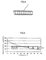
- the solubility curve in FIG. 9 the degree of solubility of such calcium carbonate in running water decreases with a rise in water temperature. This causes calcium carbonate to be deposited as a scale component.
- the scale component deposited in the above-mentioned manner is adhered to the inner wall of a water passage.
- the adhesion of the scale component has been known to be pronounced especially in the following cases: a case in which the temperature of the pipe wall becomes high; a case in which the water speed is low; a case in which the water flow is disturbed; and other cases.
- This has restricted use of heat transfer enhancers for enhancing heat transfer from the water side and made it difficult to enhance the performance of hot water supply heat exchangers.
- some hot water supply heat exchangers include a core pipe forming a water passage and a winding pipe placed around the core pipe in a spiral manner and forming a refrigerant passage and heat water flowing through the water passage by a refrigerant flowing through the refrigerant passage.
- Such hot water supply heat exchangers have already been suggested which can restrain a scale component from being adhered to the inner wall of a part of the core pipe located on the water outlet side and sufficiently secure a water passage even with the scale component adhered thereto to some extent (see Patent Document 1).
- Patent Document 1 Japanese Unexamined Patent Publication No. 2003-97898
- the present invention is made in view of the above-mentioned points, and its object is to enhance the performance of a part of a heat exchanger located on the inlet side of a water passage and having water of a predetermined temperature or less.
- a first aspect of the present invention is directed toward a hot water supply heat exchanger configured to include a water pipe 1 forming a water passage W and a refrigerant pipe 2 forming a refrigerant passage R and heat water flowing through the water passage W by a refrigerant flowing through the refrigerant passage R.
- An inlet part A of the water passage W including water of a predetermined temperature or less is provided with a heat transfer enhancer.
- the performance of heat transfer from the water side is typically lower than that from the refrigerant side, and the rate of heat transfer from the water side becomes lower in a low-temperature range than that in a high-temperature range due to the influence of physical property values (for example, the rate of heat transfer that decreases with a reduction in temperature or the viscosity coefficient that increases with a reduction in temperature).
- physical property values for example, the rate of heat transfer that decreases with a reduction in temperature or the viscosity coefficient that increases with a reduction in temperature.
- a second aspect of the present invention is directed toward a hot water supply heat exchanger configured to include a water pipe 1 forming a water passage W and a refrigerant pipe 2 forming a refrigerant passage R and heat water flowing through the water passage W by a refrigerant flowing through the refrigerant passage R.
- a part of the water pipe 1 forming an inlet part A of the water passage W having water of a predetermined temperature or less is provided with a heat transfer enhancement pipe section.
- the performance of heat transfer from the water side is typically lower than that from the refrigerant side, and the rate of heat transfer from the water side becomes lower in a low-temperature range than that in a high-temperature range due to the influence of physical property values (for example, the rate of heat transfer that decreases with a reduction in temperature or the viscosity coefficient that increases with a reduction in temperature).
- a heat transfer enhancement pipe is used as the water pipe 1 forming an inlet part A of the water passage W having water of a predetermined temperature or less, this very significantly enhances the performance of the heat exchanger.
- a third aspect of the present invention is directed toward a hot water supply heat exchanger configured to include a plurality of heat exchanger units H, H, ... including a water pipe 1 forming a part of a water passage W and a refrigerant pipe 2 forming a part of a refrigerant passage R and heat water flowing through the water passage W by a refrigerant flowing through the refrigerant passage R.
- the plurality of heat exchanger units H, H, ... are stacked one above another, the water pipes 1 are connected to one another to form a continuous water passage W, and the refrigerant pipes 2 are connected to one another to form a continuous refrigerant passage R.
- An inlet part A of the water passage W including water of a predetermined temperature or less is provided with a heat transfer enhancer.
- the performance of heat transfer from the water side is typically lower than that from the refrigerant side, and the rate of heat transfer from the water side becomes lower in a low-temperature range than that in a high-temperature range due to the influence of physical property values (for example, the rate of heat transfer that decreases with a reduction in temperature or the viscosity coefficient that increases with a reduction in temperature).
- physical property values for example, the rate of heat transfer that decreases with a reduction in temperature or the viscosity coefficient that increases with a reduction in temperature.
- a fourth aspect of the present invention is directed toward a hot water supply heat exchanger configured to include a plurality of heat exchanger units H, H, ... each including a water pipe 1 forming a part of a water passage W and a refrigerant pipe 2 forming a refrigerant passage R and heat water flowing through the water passage W by a refrigerant flowing through the refrigerant passage R.
- the plurality of heat exchanger units H, H, ... are stacked one above another.
- the water pipes 1 are connected to one another to form a continuous water passage W, and the refrigerant pipes 2 are connected to one another to form a continuous refrigerant passage R.
- a heat transfer enhancement pipe is used as the water pipe 1 corresponding to an inlet part A of the water passage W.
- the performance of heat transfer from the water side is typically lower than that from the refrigerant side, and the rate of heat transfer from the water side becomes lower in a low-temperature range than that in a high-temperature range due to the influence of physical property values (for example, the rate of heat transfer that decreases with a reduction in temperature or the viscosity coefficient that increases with a reduction in temperature).
- a heat transfer enhancement pipe is used for the heat exchanger unit H corresponding to the inlet part A of the water passage W including water of a predetermined temperature or less, this very significantly enhances the performance of the heat exchanger.
- a heat transfer enhancement pipe is used for the heat exchanger unit H partly forming an inlet part of the water passage W and including water of a predetermined temperature or less, this facilitates configuring the heat exchanger unit H and connecting the heat exchanger unit H with another heat exchanger unit.
- spiral grooves 7, 7, ... formed in the inner surface of the water pipe 1 can be adopted as the heat transfer enhancer.
- the above-described structure can enhance the heat exchange performance of the heat exchanger while suppressing problems caused by deposition of a scale component and reduce the increase in pressure loss on the water side and the cost increase to a larger extent than other heat transfer enhancement pipes.
- an internally-grooved pipe provided at its inner surface with spiral grooves 7, 7, ... can be adopted as the heat transfer enhancement pipe.
- the above-described structure can enhance the heat exchange performance of the heat exchanger while suppressing problems caused by deposition of a scale component and reduce the increase in pressure loss on the water side and the cost increase to a larger extent than other heat transfer enhancement pipes.
- the refrigerant pipe 2 in the first, second, third, fourth, fifth, or sixth aspect of the present invention, can be connected to the periphery of the water pipe 1.
- the above-mentioned structure can enhance the rate of heat transfer from the refrigerant pipe 2 to the water pipe 1, resulting in a more significantly enhanced heat exchange performance.
- a first aspect of the present invention is directed toward a hot water supply heat exchanger configured to include a water pipe 1 forming a water passage W and a refrigerant pipe 2 forming a refrigerant passage R and heat water flowing through the water passage W by a refrigerant flowing through the refrigerant passage R.
- An inlet part A of the water passage W including water of a predetermined temperature or less is provided with a heat transfer enhancer.
- the performance of heat transfer from the water side is typically lower than that from the refrigerant side, and the rate of heat transfer from the water side becomes lower in a low-temperature range than that in a high-temperature range due to the influence of physical property values (for example, the rate of heat transfer that decreases with a reduction in temperature or the viscosity coefficient that increases with a reduction in temperature).
- the inlet part A of the water passage W including water of a predetermined temperature or less is provided with the heat transfer enhancer, this very significantly enhances the performance of the heat exchanger.
- a second aspect of the present invention is directed toward a hot water supply heat exchanger configured to include a water pipe 1 forming a water passage W and a refrigerant pipe 2 forming a refrigerant passage R and heat water flowing through the water passage W by a refrigerant flowing through the refrigerant passage R.
- a heat transfer enhancement pipe is used as the water pipe 1 forming an inlet part A of the water passage W having water of a predetermined temperature or less.
- the performance of heat transfer from the water side is typically lower than that from the refrigerant side, and the rate of heat transfer from the water side becomes lower in a low-temperature range than that in a high-temperature range due to the influence of physical property values (for example, the rate of heat transfer that decreases with a reduction in temperature or the viscosity coefficient that increases with a reduction in temperature).
- the heat transfer enhancement pipe is used as the water pipe 1 forming an inlet part A of the water passage W having water of a predetermined temperature or less, this very significantly enhances the performance of the heat exchanger.
- a third aspect of the present invention is directed toward a hot water supply heat exchanger configured to include a plurality of heat exchanger units H, H, ... each including a water pipe 1 forming a part of a water passage W and a refrigerant pipe 2 forming a part of a refrigerant passage R and heat water flowing through the water passage W by a refrigerant flowing through the refrigerant passage R .
- the plurality of heat exchanger units H, H, ... are stacked one above another, the water pipes 1 are connected to one another to form a continuous water passage W , and the refrigerant pipes 2 are connected to one another to form a continuous refrigerant passage R .
- An inlet part A of the water passage W including water of a predetermined temperature or less is provided with a heat transfer enhancer.
- a heat transfer enhancer enhanced is heat transfer from the inlet part A of the water passage W including water of a predetermined temperature or less (in other words, a heat exchanger unit including water having a temperature at which calcium carbonate, i.e., a scale component, is hardly deposited) to the water side. This sharply enhances the performance of the whole heat exchanger.
- the performance of heat transfer from the water side is typically lower than that from the refrigerant side, and the rate of heat transfer from the water side becomes lower in a low-temperature range than that in a high-temperature range due to the influence of physical property values (for example, the rate of heat transfer that decreases with a reduction in temperature or the viscosity coefficient that increases with a reduction in temperature).
- physical property values for example, the rate of heat transfer that decreases with a reduction in temperature or the viscosity coefficient that increases with a reduction in temperature.
- a fourth aspect of the present invention is directed toward a hot water supply heat exchanger configured to include a plurality of heat exchanger units H, H, ... each including a water pipe 1 forming a part of a water passage W and a refrigerant pipe 2 forming a refrigerant passage R and heat water flowing through the water passage W by a refrigerant flowing through the refrigerant passage R.
- the plurality of heat exchanger units H, H, ... are stacked one above another.
- the water pipes 1 are connected to one another to form a continuous water passage W, and the refrigerant pipes 2 are connected to one another to form a continuous refrigerant passage R.
- a heat transfer enhancement pipe is used as the water pipe 1 corresponding to an inlet part A of the water passage W.
- the performance of heat transfer from the water side is typically lower than that from the refrigerant side, and the rate of heat transfer from the water side becomes lower in a low-temperature range than that in a high-temperature range due to the influence of physical property values (for example, the rate of heat transfer that decreases with a reduction in temperature or the viscosity coefficient that increases with a reduction in temperature).
- the heat transfer enhancement pipe is used for the heat exchanger unit H corresponding to the inlet part A of the water passage W including water of a predetermined temperature or less, this very significantly enhances the performance of the heat exchanger.
- a heat transfer enhancement pipe for enhancing heat transfer is used for the heat exchanger unit H partly forming an inlet part of the water passage W and including water of a predetermined temperature or less, this facilitates configuring the heat exchanger unit H and connecting the heat exchanger unit H with another heat exchanger unit.
- spiral grooves 7, 7, ... formed in the inner surface of the water pipe 1 can be adopted as the heat transfer enhancer.
- the above-described structure can enhance the heat exchange performance of the heat exchanger while suppressing problems caused by deposition of a scale component and reduce the increase in pressure loss on the water side and the cost increase to a larger extent than other heat transfer enhancement pipes.
- an internally-grooved pipe provided at its inner surface with spiral grooves 7, 7, ... can be adopted as the heat transfer enhancement pipe.
- the above-described structure can enhance the heat exchange performance of the heat exchanger while suppressing problems caused by deposition of a scale component and reduce the increase in pressure loss on the water side and the cost increase to a larger extent than other heat transfer enhancement pipes.
- the refrigerant pipe 2 in the first, second, third, fourth, fifth, or sixth aspect of the present invention, can be connected to the periphery of the water pipe 1.
- the above-mentioned structure can enhance the rate of heat transfer from the refrigerant pipe 2 to the water pipe 1, resulting in a more significantly enhanced heat exchange performance.
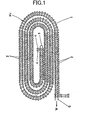
- FIG. 1 is a plan view of a hot water supply heat exchanger according to an embodiment of the present invention.
- a hot water supply heat exchanger of this embodiment serves as a heat exchanger for water used as a heater of a heat pump type hot water supply apparatus.
- this hot water supply heat exchanger is configured such that each of two heat exchanger units H1 and H2 each include a water pipe 1 forming a spiral water passage W in the form of an ellipse when viewed in plan and a refrigerant pipe 2 helically placed around the water pipe 1 to form a refrigerant passage R and are stacked one above the other.
- the water pipes 1 are connected to each other to form a continuous water passage W
- the refrigerant pipes 2 are connected to each other to form a continuous refrigerant passage R.
- the water pipe 1 for the upper heat exchanger H2 is connected near the middle of the spiral through a connector 3 to the water pipe 1 for the lower heat exchanger unit H1.
- the refrigerant pipe 2 placed around the water pipe 1 for the upper heat exchanger unit H2 is connected near the middle of the spiral through connectors 4 to the refrigerant pipe 2 placed around the water pipe 1 for the lower heat exchanger unit H1.
- An outermost part of the spiral forming the water pipe 1 for the lower heat exchanger unit H1 is provided with an inlet 5 of the water passage W.
- An outermost part of the spiral forming the water pipe 1 for the upper heat exchanger unit H2 is provided with the last outlet 6 of the water passage.
- a pipe for enhancing heat transfer (hereinafter, referred to as "heat transfer enhancement pipe") provided with a heat transfer enhancer is used as the water pipe 1 for the lower heat exchanger unit H1 forming an inlet part of the water passage W and having water of a predetermined temperature or less.
- the heat transfer enhancement pipe is used for the lower heat exchanger unit H1 forming an inlet part of the water passage W and having water of a predetermined temperature or less, this facilitates configuring the heat exchanger unit H1 and connecting the heat exchanger unit H1 with another heat exchanger unit (i.e., the upper heat exchanger unit H2).
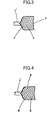
- an internally grooved pipe formed at its inner surface with spiral grooves 7, 7, ... (in other words, heat transfer enhancers) can be adopted as a heat transfer enhancement pipe 1'.
- the depth h of each groove is equal to 0.05 through 0.5 mm (preferably 0.2 mm)
- the pitch p between adjacent ones of the grooves is equal to 5 through 12 mm (preferably 7.2 mm)
- the lead angle ⁇ is equal to 5 through 30 degrees (preferably 15 degrees).
- an internally grooved pipe formed at its inner surface with asymmetrical grooves 8, 8, ... can be adopted as a heat transfer enhancement pipe 1'.
- a pipe formed at its inner surface with a cross fin 9 (in other words, a heat transfer enhancer) can be adopted as a heat transfer enhancement pipe 1'.
- a pipe formed at its inner surface with many fins 10, 10, ... (in other words, heat transfer enhancers) extending in the centripetal direction of the pipe can be adopted as a heat transfer enhancement pipe 1'.
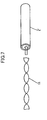
- a twisted-tape-inserted pipe into which a twisted tape 11 (in other words, a heat transfer enhancer) is inserted can be adopted as a heat transfer enhancement pipe 1'.
- a corrugated pipe illustrated in FIG. 8 can be adopted as a heat transfer enhancement pipe 1'.
- Other thin pipes can be adopted as heat transfer enhancement pipes 1'.
- respective core pipes of the first through (N-1)-th heat exchanger units from the inlet side can be heat transfer enhancement pipes.
- a water pipe 1 for a heat exchanger unit H is spirally formed, and a refrigerant pipe 2 is helically placed around the water pipe 1.
- the water pipe 1 for the heat exchanger unit H can take any other form.
- the refrigerant pipe 2 need only be connected to the periphery of the water pipe 1, and the shape of the refrigerant pipe 2 connected to the water pipe 1 can be freely chosen.
- a heat transfer enhancer at a water passage also includes a case in which a water flow disturber for disturbing the water flow (for example, a vibration-applying unit or any other unit) is provided on the inlet side of the so-constructed hot water supply heat exchanger.
- a water flow disturber for disturbing the water flow for example, a vibration-applying unit or any other unit
- the present invention is useful as hot water supply heat exchangers for heating water through a water passage by a refrigerant through a refrigerant passage.
Landscapes
- Engineering & Computer Science (AREA)
- Physics & Mathematics (AREA)
- Thermal Sciences (AREA)
- Mechanical Engineering (AREA)
- General Engineering & Computer Science (AREA)
- Geometry (AREA)
- Heat-Exchange Devices With Radiators And Conduit Assemblies (AREA)
- Heat-Pump Type And Storage Water Heaters (AREA)
- Details Of Fluid Heaters (AREA)
Abstract
Description
- The present invention relates to hot water supply heat exchangers used for heat pump type hot water supply apparatuses to exchange heat between water and a high-temperature refrigerant.
- For example, in a hot water supply heat exchanger used for a heat pump type hot water supply apparatus, a scale component dissolved in water (for example, calcium carbonate) may be deposited and adhered onto the inner wall of a water passage with a rise in water temperature. This means that calcium carbonate is dissolved in running water. As illustrated by the solubility curve in FIG. 9, the degree of solubility of such calcium carbonate in running water decreases with a rise in water temperature. This causes calcium carbonate to be deposited as a scale component. The scale component deposited in the above-mentioned manner is adhered to the inner wall of a water passage. The adhesion of the scale component has been known to be pronounced especially in the following cases: a case in which the temperature of the pipe wall becomes high; a case in which the water speed is low; a case in which the water flow is disturbed; and other cases. This has restricted use of heat transfer enhancers for enhancing heat transfer from the water side and made it difficult to enhance the performance of hot water supply heat exchangers.
- By the way, some hot water supply heat exchangers include a core pipe forming a water passage and a winding pipe placed around the core pipe in a spiral manner and forming a refrigerant passage and heat water flowing through the water passage by a refrigerant flowing through the refrigerant passage. Such hot water supply heat exchangers have already been suggested which can restrain a scale component from being adhered to the inner wall of a part of the core pipe located on the water outlet side and sufficiently secure a water passage even with the scale component adhered thereto to some extent (see Patent Document 1).
Patent Document 1:Japanese Unexamined Patent Publication No. 2003-97898 - However, for the hot water supply heat exchanger disclosed in the Patent Document 1, the problem that a scale component is adhered to the water outlet side can be solved but the performance of heat exchangers themselves cannot be enhanced.
- The present inventors noticed that the performance of heat exchangers can be enhanced by both restraining adhesion of a scale component and enhancing heat transfer. This led to the present invention.
- The present invention is made in view of the above-mentioned points, and its object is to enhance the performance of a part of a heat exchanger located on the inlet side of a water passage and having water of a predetermined temperature or less.
- A first aspect of the present invention is directed toward a hot water supply heat exchanger configured to include a water pipe 1 forming a water passage W and a
refrigerant pipe 2 forming a refrigerant passage R and heat water flowing through the water passage W by a refrigerant flowing through the refrigerant passage R. An inlet part A of the water passage W including water of a predetermined temperature or less is provided with a heat transfer enhancer. - With the above-mentioned structure, enhanced is heat transfer from the inlet part A of the water passage W including water of a predetermined temperature or less (in other words, a heat exchanger unit including water having a temperature at which calcium carbonate, i.e., a scale component, is hardly deposited) to the water side. This sharply enhances the performance of the whole heat exchanger. In particular, when the so-constructed hot water supply heat exchanger is used for a heat pump type hot water supply apparatus, the performance of heat transfer from the water side is typically lower than that from the refrigerant side, and the rate of heat transfer from the water side becomes lower in a low-temperature range than that in a high-temperature range due to the influence of physical property values (for example, the rate of heat transfer that decreases with a reduction in temperature or the viscosity coefficient that increases with a reduction in temperature). In view of the above, when the inlet part A of the water passage W including water of a predetermined temperature or less is provided with the heat transfer enhancer, this very significantly enhances the performance of the heat exchanger.
- A second aspect of the present invention is directed toward a hot water supply heat exchanger configured to include a water pipe 1 forming a water passage W and a
refrigerant pipe 2 forming a refrigerant passage R and heat water flowing through the water passage W by a refrigerant flowing through the refrigerant passage R. A part of the water pipe 1 forming an inlet part A of the water passage W having water of a predetermined temperature or less is provided with a heat transfer enhancement pipe section. - With the above-mentioned structure, enhanced is heat transfer from the inlet part A of the water passage W including water of a predetermined temperature or less (in other words, a heat exchanger unit including water having a temperature at which calcium carbonate, i.e., a scale component, is hardly deposited) to the water side. This sharply enhances the performance of the whole heat exchanger. In particular, when the so-constructed hot water supply heat exchanger is used for a heat pump type hot water supply apparatus, the performance of heat transfer from the water side is typically lower than that from the refrigerant side, and the rate of heat transfer from the water side becomes lower in a low-temperature range than that in a high-temperature range due to the influence of physical property values (for example, the rate of heat transfer that decreases with a reduction in temperature or the viscosity coefficient that increases with a reduction in temperature). In view of the above, when a heat transfer enhancement pipe is used as the water pipe 1 forming an inlet part A of the water passage W having water of a predetermined temperature or less, this very significantly enhances the performance of the heat exchanger.
- A third aspect of the present invention is directed toward a hot water supply heat exchanger configured to include a plurality of heat exchanger units H, H, ... including a water pipe 1 forming a part of a water passage W and a
refrigerant pipe 2 forming a part of a refrigerant passage R and heat water flowing through the water passage W by a refrigerant flowing through the refrigerant passage R. The plurality of heat exchanger units H, H, ... are stacked one above another, the water pipes 1 are connected to one another to form a continuous water passage W, and therefrigerant pipes 2 are connected to one another to form a continuous refrigerant passage R. An inlet part A of the water passage W including water of a predetermined temperature or less is provided with a heat transfer enhancer. - With the above-mentioned structure, enhanced is heat transfer from the inlet part A of the water passage W including water of a predetermined temperature or less (in other words, a heat exchanger unit including water having a temperature at which calcium carbonate, i.e., a scale component, is hardly deposited) to the water side. This sharply enhances the performance of the whole heat exchanger. In particular, when the so-constructed hot water supply heat exchanger is used for a heat pump type hot water supply apparatus, the performance of heat transfer from the water side is typically lower than that from the refrigerant side, and the rate of heat transfer from the water side becomes lower in a low-temperature range than that in a high-temperature range due to the influence of physical property values (for example, the rate of heat transfer that decreases with a reduction in temperature or the viscosity coefficient that increases with a reduction in temperature). In view of the above, when the inlet part A of the water passage W including water of a predetermined temperature or less is provided with a heat transfer enhancer, this very significantly enhances the performance of the heat exchanger.
- A fourth aspect of the present invention is directed toward a hot water supply heat exchanger configured to include a plurality of heat exchanger units H, H, ... each including a water pipe 1 forming a part of a water passage W and a
refrigerant pipe 2 forming a refrigerant passage R and heat water flowing through the water passage W by a refrigerant flowing through the refrigerant passage R. The plurality of heat exchanger units H, H, ... are stacked one above another. The water pipes 1 are connected to one another to form a continuous water passage W, and therefrigerant pipes 2 are connected to one another to form a continuous refrigerant passage R. A heat transfer enhancement pipe is used as the water pipe 1 corresponding to an inlet part A of the water passage W. - With the above-mentioned structure, enhanced is heat transfer from the inlet part A of the water passage W including water of a predetermined temperature or less (in other words, a heat exchanger unit including water having a temperature at which calcium carbonate, i.e., a scale component, is hardly deposited) to the water side. This sharply enhances the performance of the whole heat exchanger. In particular, when the so-constructed hot water supply heat exchanger is used for a heat pump type hot water supply apparatus, the performance of heat transfer from the water side is typically lower than that from the refrigerant side, and the rate of heat transfer from the water side becomes lower in a low-temperature range than that in a high-temperature range due to the influence of physical property values (for example, the rate of heat transfer that decreases with a reduction in temperature or the viscosity coefficient that increases with a reduction in temperature). In view of the above, when a heat transfer enhancement pipe is used for the heat exchanger unit H corresponding to the inlet part A of the water passage W including water of a predetermined temperature or less, this very significantly enhances the performance of the heat exchanger. In addition, since a heat transfer enhancement pipe is used for the heat exchanger unit H partly forming an inlet part of the water passage W and including water of a predetermined temperature or less, this facilitates configuring the heat exchanger unit H and connecting the heat exchanger unit H with another heat exchanger unit.
- According to a fifth aspect of the present invention, in the first or third aspect of the present invention,
spiral grooves - According to a sixth aspect of the present invention, in the second or fourth aspect of the present invention, an internally-grooved pipe provided at its inner surface with
spiral grooves - According to a seventh aspect of the present invention, in the first, second, third, fourth, fifth, or sixth aspect of the present invention, the
refrigerant pipe 2 can be connected to the periphery of the water pipe 1. The above-mentioned structure can enhance the rate of heat transfer from therefrigerant pipe 2 to the water pipe 1, resulting in a more significantly enhanced heat exchange performance. - A first aspect of the present invention is directed toward a hot water supply heat exchanger configured to include a water pipe 1 forming a water passage W and a
refrigerant pipe 2 forming a refrigerant passage R and heat water flowing through the water passage W by a refrigerant flowing through the refrigerant passage R. An inlet part A of the water passage W including water of a predetermined temperature or less is provided with a heat transfer enhancer. With the above-mentioned structure, enhanced is heat transfer from the inlet part A of the water passage W including water of a predetermined temperature or less (in other words, a heat exchanger unit including water having a temperature at which calcium carbonate, i.e., a scale component, is hardly deposited) to the water side. This sharply enhances the performance of the whole heat exchanger. In particular, when the so-constructed hot water supply heat exchanger is used for a heat pump type hot water supply apparatus, the performance of heat transfer from the water side is typically lower than that from the refrigerant side, and the rate of heat transfer from the water side becomes lower in a low-temperature range than that in a high-temperature range due to the influence of physical property values (for example, the rate of heat transfer that decreases with a reduction in temperature or the viscosity coefficient that increases with a reduction in temperature). In view of the above, when the inlet part A of the water passage W including water of a predetermined temperature or less is provided with the heat transfer enhancer, this very significantly enhances the performance of the heat exchanger. - A second aspect of the present invention is directed toward a hot water supply heat exchanger configured to include a water pipe 1 forming a water passage W and a
refrigerant pipe 2 forming a refrigerant passage R and heat water flowing through the water passage W by a refrigerant flowing through the refrigerant passage R. A heat transfer enhancement pipe is used as the water pipe 1 forming an inlet part A of the water passage W having water of a predetermined temperature or less. With the above-mentioned structure, enhanced is heat transfer from the inlet part A of the water passage W including water of a predetermined temperature or less (in other words, a heat exchanger unit including water having a temperature at which calcium carbonate, i.e., a scale component, is hardly deposited) to the water side. This sharply enhances the performance of the whole heat exchanger. In particular, when the so-constructed hot water supply heat exchanger is used for a heat pump type hot water supply apparatus, the performance of heat transfer from the water side is typically lower than that from the refrigerant side, and the rate of heat transfer from the water side becomes lower in a low-temperature range than that in a high-temperature range due to the influence of physical property values (for example, the rate of heat transfer that decreases with a reduction in temperature or the viscosity coefficient that increases with a reduction in temperature). In view of the above, when the heat transfer enhancement pipe is used as the water pipe 1 forming an inlet part A of the water passage W having water of a predetermined temperature or less, this very significantly enhances the performance of the heat exchanger. - A third aspect of the present invention is directed toward a hot water supply heat exchanger configured to include a plurality of heat exchanger units H, H, ... each including a water pipe 1 forming a part of a water passage W and a
refrigerant pipe 2 forming a part of a refrigerant passage R and heat water flowing through the water passage W by a refrigerant flowing through the refrigerant passage R. The plurality of heat exchanger units H, H, ... are stacked one above another, the water pipes 1 are connected to one another to form a continuous water passage W, and therefrigerant pipes 2 are connected to one another to form a continuous refrigerant passage R. An inlet part A of the water passage W including water of a predetermined temperature or less is provided with a heat transfer enhancer. With the above-mentioned structure, enhanced is heat transfer from the inlet part A of the water passage W including water of a predetermined temperature or less (in other words, a heat exchanger unit including water having a temperature at which calcium carbonate, i.e., a scale component, is hardly deposited) to the water side. This sharply enhances the performance of the whole heat exchanger. In particular, when the so-constructed hot water supply heat exchanger is used for a heat pump type hot water supply apparatus, the performance of heat transfer from the water side is typically lower than that from the refrigerant side, and the rate of heat transfer from the water side becomes lower in a low-temperature range than that in a high-temperature range due to the influence of physical property values (for example, the rate of heat transfer that decreases with a reduction in temperature or the viscosity coefficient that increases with a reduction in temperature). In view of the above, when the inlet part A of the water passage W including water of a predetermined temperature or less is provided with the heat transfer enhancer, this very significantly enhances the performance of the heat exchanger. - A fourth aspect of the present invention is directed toward a hot water supply heat exchanger configured to include a plurality of heat exchanger units H, H, ... each including a water pipe 1 forming a part of a water passage W and a
refrigerant pipe 2 forming a refrigerant passage R and heat water flowing through the water passage W by a refrigerant flowing through the refrigerant passage R. The plurality of heat exchanger units H, H, ... are stacked one above another. The water pipes 1 are connected to one another to form a continuous water passage W, and therefrigerant pipes 2 are connected to one another to form a continuous refrigerant passage R. A heat transfer enhancement pipe is used as the water pipe 1 corresponding to an inlet part A of the water passage W. With the above-mentioned structure, enhanced is heat transfer from the inlet part A of the water passage W including water of a predetermined temperature or less (in other words, a heat exchanger unit including water having a temperature at which calcium carbonate, i.e., a scale component, is hardly deposited) to the water side. This sharply enhances the performance of the whole heat exchanger. In particular, when the so-constructed hot water supply heat exchanger is used for a heat pump type hot water supply apparatus, the performance of heat transfer from the water side is typically lower than that from the refrigerant side, and the rate of heat transfer from the water side becomes lower in a low-temperature range than that in a high-temperature range due to the influence of physical property values (for example, the rate of heat transfer that decreases with a reduction in temperature or the viscosity coefficient that increases with a reduction in temperature). In view of the above, when the heat transfer enhancement pipe is used for the heat exchanger unit H corresponding to the inlet part A of the water passage W including water of a predetermined temperature or less, this very significantly enhances the performance of the heat exchanger. In addition, since a heat transfer enhancement pipe for enhancing heat transfer is used for the heat exchanger unit H partly forming an inlet part of the water passage W and including water of a predetermined temperature or less, this facilitates configuring the heat exchanger unit H and connecting the heat exchanger unit H with another heat exchanger unit. - According to a fifth aspect of the present invention, in the first or third aspect of the present invention,
spiral grooves - According to a sixth aspect of the present invention, in the second or fourth aspect of the present invention, an internally-grooved pipe provided at its inner surface with
spiral grooves - According to a seventh aspect of the present invention, in the first, second, third, fourth, fifth, or sixth aspect of the present invention, the
refrigerant pipe 2 can be connected to the periphery of the water pipe 1. The above-mentioned structure can enhance the rate of heat transfer from therefrigerant pipe 2 to the water pipe 1, resulting in a more significantly enhanced heat exchange performance. - [FIG. 1] FIG. 1 is a plan view of a hot water supply heat exchanger according to an embodiment of the present invention.
- [FIG. 2] FIG. 2 is a side view of a hot water supply heat exchanger according to the embodiment of the present invention.
- [FIG. 3] FIG. 3 is a partially developed plan view illustrating an exemplary heat transfer enhancement pipe adopted for the hot water supply heat exchanger according to the embodiment of the present invention.
- [FIG. 4] FIG. 4 is a partially developed plan view illustrating another exemplary heat transfer enhancement pipe adopted for the hot water supply heat exchanger according to the embodiment of the present invention.
- [FIG. 5] FIG. 5 is a partially developed plan view illustrating still another exemplary heat transfer enhancement pipe adopted for the hot water supply heat exchanger according to the embodiment of the present invention.
- [FIG. 6] FIG. 6 is a partially developed plan view illustrating yet another exemplary heat transfer enhancement pipe adopted for the hot water supply heat exchanger according to the embodiment of the present invention.
- [FIG. 7] FIG. 7 is a partially developed plan view illustrating a further exemplary heat transfer enhancement pipe adopted for the hot water supply heat exchanger according to the embodiment of the present invention.
- [FIG. 8] FIG. 8 is a partially developed plan view illustrating a still further exemplary heat transfer enhancement pipe adopted for the hot water supply heat exchanger according to the embodiment of the present invention.
- [FIG. 9] FIG. 9 is a characteristic graph illustrating the solubility curve of calcium carbonate.
-
- 1
- water pipe
- 1'
- heat transfer enhancement pipe
- 2
- refrigerant pipe
- 7
- spiral grooves
- A
- inlet part
- H(H1, H2)
- heat exchanger unit
- R
- refrigerant passage
- W
- water passage
- A preferred embodiment of the present invention will be described hereinafter with reference to the accompanying drawings.
- A hot water supply heat exchanger of this embodiment serves as a heat exchanger for water used as a heater of a heat pump type hot water supply apparatus. As illustrated in FIGS. 1 and 2, this hot water supply heat exchanger is configured such that each of two heat exchanger units H1 and H2 each include a water pipe 1 forming a spiral water passage W in the form of an ellipse when viewed in plan and a
refrigerant pipe 2 helically placed around the water pipe 1 to form a refrigerant passage R and are stacked one above the other. Furthermore, the water pipes 1 are connected to each other to form a continuous water passage W, and therefrigerant pipes 2 are connected to each other to form a continuous refrigerant passage R. - The water pipe 1 for the upper heat exchanger H2 is connected near the middle of the spiral through a
connector 3 to the water pipe 1 for the lower heat exchanger unit H1. Therefrigerant pipe 2 placed around the water pipe 1 for the upper heat exchanger unit H2 is connected near the middle of the spiral throughconnectors 4 to therefrigerant pipe 2 placed around the water pipe 1 for the lower heat exchanger unit H1. An outermost part of the spiral forming the water pipe 1 for the lower heat exchanger unit H1 is provided with aninlet 5 of the water passage W. An outermost part of the spiral forming the water pipe 1 for the upper heat exchanger unit H2 is provided with the last outlet 6 of the water passage. - A pipe for enhancing heat transfer (hereinafter, referred to as "heat transfer enhancement pipe") provided with a heat transfer enhancer is used as the water pipe 1 for the lower heat exchanger unit H1 forming an inlet part of the water passage W and having water of a predetermined temperature or less.
- With the above-mentioned structure, enhanced is heat transfer from the water pipe 1 for the lower heat exchanger unit H1 forming an inlet part of the water passage W and having water of a predetermined temperature or less (in other words, a heat exchanger unit including water having a temperature at which calcium carbonate, i.e., a scale component, is hardly deposited) to the water side. This sharply enhances the performance of the whole heat exchanger. In addition, since the heat transfer enhancement pipe is used for the lower heat exchanger unit H1 forming an inlet part of the water passage W and having water of a predetermined temperature or less, this facilitates configuring the heat exchanger unit H1 and connecting the heat exchanger unit H1 with another heat exchanger unit (i.e., the upper heat exchanger unit H2).
- Various pipes that have conventionally been well known can be used as heat transfer enhancement pipes. Such pipes are typified by the following pipes.
- As illustrated in FIG. 3, an internally grooved pipe formed at its inner surface with
spiral grooves asymmetrical grooves many fins - When three or more heat exchanger units H, H, ... are stacked one above another and the number of the heat exchanger units H, H, ... is N, respective core pipes of the first through (N-1)-th heat exchanger units from the inlet side can be heat transfer enhancement pipes.
- In the above embodiment, a water pipe 1 for a heat exchanger unit H is spirally formed, and a
refrigerant pipe 2 is helically placed around the water pipe 1. However, the water pipe 1 for the heat exchanger unit H can take any other form. Furthermore, therefrigerant pipe 2 need only be connected to the periphery of the water pipe 1, and the shape of therefrigerant pipe 2 connected to the water pipe 1 can be freely chosen. - The above-mentioned provision of a heat transfer enhancer at a water passage also includes a case in which a water flow disturber for disturbing the water flow (for example, a vibration-applying unit or any other unit) is provided on the inlet side of the so-constructed hot water supply heat exchanger.
- Furthermore, the present invention is not limited to the above embodiment, and it is apparent that various modifications may be made.
- As described above, the present invention is useful as hot water supply heat exchangers for heating water through a water passage by a refrigerant through a refrigerant passage.
Claims (7)
- A hot water supply heat exchanger comprising a water pipe (1) forming a water passage (W) and a refrigerant pipe (2) forming a refrigerant passage (R), the hot water supply heat exchanger being for heating water flowing through the water passage (W) by a refrigerant flowing through the refrigerant passage (R),
wherein an inlet part (A) of the water passage (W) having water of a predetermined temperature or less is provided with a heat transfer enhancer. - A hot water supply heat exchanger comprising a water pipe (1) forming a water passage (W) and a refrigerant pipe (2) forming a refrigerant passage (R), the hot water supply heat exchanger being for heating water flowing through the water passage (W) by a refrigerant flowing through the refrigerant passage (R),
wherein a part of the water pipe (1) forming an inlet part (A) of the water passage (W) having water of a predetermined temperature or less is provided with a heat transfer enhancement pipe section. - A hot water supply heat exchanger comprising a plurality of heat exchanger units (H, H, ...) each including a water pipe (1) forming a part of a water passage (W) and a refrigerant pipe (2) forming a part of a refrigerant passage (R), said plurality of heat exchanger units (H, H, ...) being stacked one above another, the water pipes (1) being connected to one another to form a continuous water passage (W), the refrigerant pipes (2) being connected to one another to form a continuous refrigerant passage (R), said hot water supply heat exchanger being for heating water flowing through the water passage (W) by a refrigerant flowing through the refrigerant passage (R),
wherein an inlet part (A) of the water passage (W) including water of a predetermined temperature or less is provided with a heat transfer enhancer. - A hot water supply heat exchanger comprising a plurality of heat exchanger units (H, H, ...) each including a water pipe (1) forming a part of a water passage (W) and a refrigerant pipe (2) forming a refrigerant passage (R), said plurality of heat exchanger units (H, H, ...) being stacked one above another, the water pipes (1) being connected to one another to form a continuous water passage (W), the refrigerant pipes (2) being connected to one another to form a continuous refrigerant passage (R), said hot water supply heat exchanger being for heating water flowing through the water passage (W) by a refrigerant flowing through the refrigerant passage (R),
wherein a heat transfer enhancement pipe is used as the water pipe (1) corresponding to an inlet part (A) of the water passage (W). - The hot water supply heat exchanger of Claim 1 or 3, wherein
spiral grooves (7, 7, ...) formed in the inner surface of the water pipe (1) are adopted as the heat transfer enhancer. - The hot water supply heat exchanger of Claim 2 or 4, wherein
an internally-grooved pipe provided at its inner surface with spiral grooves (7, 7, ...) is adopted as the heat transfer enhancement pipe. - The hot water supply heat exchanger of any one of Claims 1 through 4, wherein
the refrigerant pipe (2) is connected to the periphery of the water pipe (1).
Applications Claiming Priority (2)
| Application Number | Priority Date | Filing Date | Title |
|---|---|---|---|
| JP2004030600A JP4501446B2 (en) | 2004-02-06 | 2004-02-06 | Heat exchanger for hot water supply |
| PCT/JP2005/001687 WO2005075914A1 (en) | 2004-02-06 | 2005-02-04 | Heat exchanger for hot water supply |
Publications (2)
| Publication Number | Publication Date |
|---|---|
| EP1719964A1 true EP1719964A1 (en) | 2006-11-08 |
| EP1719964A4 EP1719964A4 (en) | 2013-11-06 |
Family
ID=34836007
Family Applications (1)
| Application Number | Title | Priority Date | Filing Date |
|---|---|---|---|
| EP05709752.9A Withdrawn EP1719964A4 (en) | 2004-02-06 | 2005-02-04 | HEAT CHANGER FOR HOT WATER SUPPLY |
Country Status (5)
| Country | Link |
|---|---|
| US (1) | US20070119578A1 (en) |
| EP (1) | EP1719964A4 (en) |
| JP (1) | JP4501446B2 (en) |
| CN (1) | CN1914470A (en) |
| WO (1) | WO2005075914A1 (en) |
Cited By (2)
| Publication number | Priority date | Publication date | Assignee | Title |
|---|---|---|---|---|
| EP2249098A4 (en) * | 2008-02-01 | 2016-03-09 | Daikin Ind Ltd | HOT WATER SUPPLY DEVICE HAVING WATER HEATING AND HOT WATER STORAGE |
| EP3171116A1 (en) * | 2015-11-21 | 2017-05-24 | Linde Aktiengesellschaft | Wound heat exchanger comprising turbulators |
Families Citing this family (11)
| Publication number | Priority date | Publication date | Assignee | Title |
|---|---|---|---|---|
| CN1924507A (en) * | 2006-09-08 | 2007-03-07 | 清华大学 | Helical groove heat exchange pipe for water heater |
| DE102007007229A1 (en) * | 2007-02-14 | 2008-08-21 | Behr Gmbh & Co. Kg | Heat exchanger, particularly fuel cooler, has inner tube, in which refrigerant is flowing and flow channel is provided at outside of inner tube, in which liquid gas for combustion engine is flowing |
| JP2008215766A (en) * | 2007-03-07 | 2008-09-18 | Daikin Ind Ltd | Heat exchanger for hot water supply |
| JP2008267790A (en) * | 2007-03-27 | 2008-11-06 | Daikin Ind Ltd | Heat pump type hot water supply device and heating hot water supply device |
| JP4787284B2 (en) * | 2007-03-27 | 2011-10-05 | ダイキン工業株式会社 | Heat pump type water heater |
| JP2008275302A (en) * | 2007-03-30 | 2008-11-13 | Daikin Ind Ltd | Heating and hot water supply equipment |
| CN101622502A (en) * | 2007-03-30 | 2010-01-06 | 大金工业株式会社 | Heating hot water supply apparatus |
| JP2008281263A (en) * | 2007-05-09 | 2008-11-20 | Hitachi Cable Ltd | Heat exchanger |
| JP4713562B2 (en) * | 2007-11-21 | 2011-06-29 | 三菱電機株式会社 | Heat exchanger and heat pump water heater using the same |
| US8385729B2 (en) | 2009-09-08 | 2013-02-26 | Rheem Manufacturing Company | Heat pump water heater and associated control system |
| JP5269062B2 (en) * | 2010-12-27 | 2013-08-21 | 三菱電機株式会社 | Heat pump water heater |
Family Cites Families (20)
| Publication number | Priority date | Publication date | Assignee | Title |
|---|---|---|---|---|
| US1833876A (en) * | 1929-01-31 | 1931-11-24 | Standard Oil Dev Co | Pipe coil heat exchange equipment |
| US2611585A (en) * | 1948-03-30 | 1952-09-23 | Heat X Changer Co Inc | Heat exchanger |
| FR1252033A (en) * | 1959-04-28 | 1961-01-27 | Rough Surface Heat Exchanger Tubes | |
| DE2153654A1 (en) * | 1970-11-18 | 1972-05-25 | Luft U Kaeltetechnik Veb K | Forced-through heat exchanger in lightweight construction, preferably for air conditioning units with compression refrigeration systems |
| US3777343A (en) * | 1971-03-11 | 1973-12-11 | Spiral Tubing Corp | Method for forming a helically corrugated concentric tubing unit |
| US3902552A (en) * | 1973-05-10 | 1975-09-02 | Olin Corp | Patterned tubing |
| JPS56137095A (en) * | 1980-03-28 | 1981-10-26 | Hitachi Cable Ltd | Thermal conductive pipe |
| FR2697077B1 (en) * | 1992-10-16 | 1994-12-30 | Sofath | Device for improving the performance of heat pumps with an underground sensor. |
| JPH08105699A (en) * | 1994-10-03 | 1996-04-23 | Hitachi Cable Ltd | Heat transfer tube with internal groove |
| JPH0972683A (en) * | 1995-09-04 | 1997-03-18 | Hitachi Cable Ltd | Heat transfer tube |
| US5791401A (en) * | 1996-05-13 | 1998-08-11 | Nobile; John R. | Heat recovery device for showers |
| US6510687B1 (en) * | 1996-06-14 | 2003-01-28 | Sharav Sluices Ltd. | Renewable resource hydro/aero-power generation plant and method of generating hydro/aero-power |
| CA2367726C (en) * | 1999-09-23 | 2010-10-19 | Joseph C. Ferraro | External flue heat exchangers |
| JP2001201275A (en) * | 2000-01-21 | 2001-07-27 | Daikin Ind Ltd | Double tube heat exchanger |
| JP2002228370A (en) * | 2001-01-30 | 2002-08-14 | Daikin Ind Ltd | Heat exchanger |
| JP3649181B2 (en) * | 2001-07-16 | 2005-05-18 | ダイキン工業株式会社 | Heat exchanger |
| JP3587189B2 (en) * | 2001-11-19 | 2004-11-10 | ダイキン工業株式会社 | Heat exchanger |
| US20040108096A1 (en) * | 2002-11-27 | 2004-06-10 | Janssen Terrance Ernest | Geothermal loopless exchanger |
| JP3811123B2 (en) * | 2002-12-10 | 2006-08-16 | 松下電器産業株式会社 | Double tube heat exchanger |
| US6988542B2 (en) * | 2003-02-06 | 2006-01-24 | Modine Manufacturing Company | Heat exchanger |
-
2004
- 2004-02-06 JP JP2004030600A patent/JP4501446B2/en not_active Expired - Lifetime
-
2005
- 2005-02-04 CN CNA2005800040652A patent/CN1914470A/en active Pending
- 2005-02-04 EP EP05709752.9A patent/EP1719964A4/en not_active Withdrawn
- 2005-02-04 US US10/588,228 patent/US20070119578A1/en not_active Abandoned
- 2005-02-04 WO PCT/JP2005/001687 patent/WO2005075914A1/en not_active Ceased
Cited By (2)
| Publication number | Priority date | Publication date | Assignee | Title |
|---|---|---|---|---|
| EP2249098A4 (en) * | 2008-02-01 | 2016-03-09 | Daikin Ind Ltd | HOT WATER SUPPLY DEVICE HAVING WATER HEATING AND HOT WATER STORAGE |
| EP3171116A1 (en) * | 2015-11-21 | 2017-05-24 | Linde Aktiengesellschaft | Wound heat exchanger comprising turbulators |
Also Published As
| Publication number | Publication date |
|---|---|
| JP2005221172A (en) | 2005-08-18 |
| WO2005075914A1 (en) | 2005-08-18 |
| CN1914470A (en) | 2007-02-14 |
| EP1719964A4 (en) | 2013-11-06 |
| US20070119578A1 (en) | 2007-05-31 |
| JP4501446B2 (en) | 2010-07-14 |
Similar Documents
| Publication | Publication Date | Title |
|---|---|---|
| US20070119578A1 (en) | Hot water supply heat exchanger | |
| EP3228971B1 (en) | Spiral tube heat exchanger | |
| JP4674602B2 (en) | Heat exchanger | |
| JP2007218486A (en) | Heat exchanger tube for heat exchanger and heat exchanger using the same | |
| EP2454447B1 (en) | Subsea cooler | |
| JP2008232449A (en) | Double tube heat exchanger and method for manufacturing the same | |
| US20050269069A1 (en) | Heat transfer apparatus with enhanced micro-channel heat transfer tubing | |
| EP2322892A1 (en) | Heat exchanger and heat pump device using same | |
| CN103363820A (en) | Heat transfer tubes and a heat exchanger using the same | |
| KR20050027407A (en) | Heat exchanger | |
| CN103608639B (en) | Fin tube heat exchanger | |
| EP3306254A1 (en) | Heat exchanger tank structure and production method therefor | |
| US20130299132A1 (en) | Heat exchanger assembly and method of manufacturing therefor | |
| JP4420117B2 (en) | Heat exchanger tube for heat exchanger and heat exchanger using the same | |
| JP2002228370A (en) | Heat exchanger | |
| US11555659B2 (en) | Multi-scale heat exchanger core | |
| JP2008261566A (en) | Double tube heat exchanger | |
| JP4063237B2 (en) | Heat exchange device and heat pump water heater using the same | |
| US7546867B2 (en) | Spirally wound, layered tube heat exchanger | |
| CN102401597B (en) | Heat transfer tube of heat exchanger and use its heat exchanger | |
| EP3754284A1 (en) | Heat exchanger and refrigeration cycle device | |
| EP3575728B1 (en) | A core of a heat exchanger comprising corrugated fins | |
| CN209263726U (en) | Heat exchanger | |
| CN111964516A (en) | Inserts that generate turbulence | |
| CN101806551B (en) | Heat exchanger and heat transfer tube |
Legal Events
| Date | Code | Title | Description |
|---|---|---|---|
| PUAI | Public reference made under article 153(3) epc to a published international application that has entered the european phase |
Free format text: ORIGINAL CODE: 0009012 |
|
| 17P | Request for examination filed |
Effective date: 20060823 |
|
| AK | Designated contracting states |
Kind code of ref document: A1 Designated state(s): AT BE BG CH CY CZ DE DK EE ES FI FR GB GR HU IE IS IT LI LT LU MC NL PL PT RO SE SI SK TR |
|
| DAX | Request for extension of the european patent (deleted) | ||
| A4 | Supplementary search report drawn up and despatched |
Effective date: 20131007 |
|
| RIC1 | Information provided on ipc code assigned before grant |
Ipc: F28F 1/40 20060101ALI20130930BHEP Ipc: F24H 9/00 20060101ALI20130930BHEP Ipc: F24H 1/00 20060101ALI20130930BHEP Ipc: F28D 7/00 20060101AFI20130930BHEP Ipc: F28F 1/10 20060101ALI20130930BHEP Ipc: F28D 7/02 20060101ALN20130930BHEP |
|
| 17Q | First examination report despatched |
Effective date: 20160707 |
|
| STAA | Information on the status of an ep patent application or granted ep patent |
Free format text: STATUS: THE APPLICATION IS DEEMED TO BE WITHDRAWN |
|
| 18D | Application deemed to be withdrawn |
Effective date: 20161118 |