EP1719930A2 - Clutch plate assembly for multiple disc clutch, especially twin-plate clutch - Google Patents
Clutch plate assembly for multiple disc clutch, especially twin-plate clutch Download PDFInfo
- Publication number
- EP1719930A2 EP1719930A2 EP06008476A EP06008476A EP1719930A2 EP 1719930 A2 EP1719930 A2 EP 1719930A2 EP 06008476 A EP06008476 A EP 06008476A EP 06008476 A EP06008476 A EP 06008476A EP 1719930 A2 EP1719930 A2 EP 1719930A2
- Authority
- EP
- European Patent Office
- Prior art keywords
- driver
- clutch
- cover disk
- clutch disc
- projections
- Prior art date
- Legal status (The legal status is an assumption and is not a legal conclusion. Google has not performed a legal analysis and makes no representation as to the accuracy of the status listed.)
- Granted
Links
- 230000008878 coupling Effects 0.000 claims abstract description 30
- 238000010168 coupling process Methods 0.000 claims abstract description 30
- 238000005859 coupling reaction Methods 0.000 claims abstract description 30
- 230000015572 biosynthetic process Effects 0.000 claims description 55
- 230000000712 assembly Effects 0.000 claims description 19
- 238000000429 assembly Methods 0.000 claims description 19
- 210000000746 body region Anatomy 0.000 claims description 7
- 238000003466 welding Methods 0.000 claims description 4
- 238000006073 displacement reaction Methods 0.000 claims description 2
- 239000000463 material Substances 0.000 claims description 2
- 230000001419 dependent effect Effects 0.000 claims 1
- 230000010355 oscillation Effects 0.000 abstract 2
- 230000003993 interaction Effects 0.000 description 8
- 230000005540 biological transmission Effects 0.000 description 4
- 239000000725 suspension Substances 0.000 description 4
- 238000004519 manufacturing process Methods 0.000 description 3
- 230000004048 modification Effects 0.000 description 3
- 238000012986 modification Methods 0.000 description 3
- 238000005452 bending Methods 0.000 description 2
- 230000006835 compression Effects 0.000 description 2
- 238000007906 compression Methods 0.000 description 2
- 238000013016 damping Methods 0.000 description 2
- 230000002093 peripheral effect Effects 0.000 description 2
- 239000007787 solid Substances 0.000 description 2
- 238000003860 storage Methods 0.000 description 2
- FGRBYDKOBBBPOI-UHFFFAOYSA-N 10,10-dioxo-2-[4-(N-phenylanilino)phenyl]thioxanthen-9-one Chemical compound O=C1c2ccccc2S(=O)(=O)c2ccc(cc12)-c1ccc(cc1)N(c1ccccc1)c1ccccc1 FGRBYDKOBBBPOI-UHFFFAOYSA-N 0.000 description 1
- TVEXGJYMHHTVKP-UHFFFAOYSA-N 6-oxabicyclo[3.2.1]oct-3-en-7-one Chemical compound C1C2C(=O)OC1C=CC2 TVEXGJYMHHTVKP-UHFFFAOYSA-N 0.000 description 1
- 230000008901 benefit Effects 0.000 description 1
- 238000002485 combustion reaction Methods 0.000 description 1
- 230000000295 complement effect Effects 0.000 description 1
- 150000001875 compounds Chemical class 0.000 description 1
- 238000010276 construction Methods 0.000 description 1
- 238000005520 cutting process Methods 0.000 description 1
- 230000000694 effects Effects 0.000 description 1
- 238000003780 insertion Methods 0.000 description 1
- 230000037431 insertion Effects 0.000 description 1
- 238000005304 joining Methods 0.000 description 1
- 238000000034 method Methods 0.000 description 1
- 230000008569 process Effects 0.000 description 1
- 238000004080 punching Methods 0.000 description 1
- 238000007493 shaping process Methods 0.000 description 1
- 125000006850 spacer group Chemical group 0.000 description 1
Images


Classifications
-
- F—MECHANICAL ENGINEERING; LIGHTING; HEATING; WEAPONS; BLASTING
- F16—ENGINEERING ELEMENTS AND UNITS; GENERAL MEASURES FOR PRODUCING AND MAINTAINING EFFECTIVE FUNCTIONING OF MACHINES OR INSTALLATIONS; THERMAL INSULATION IN GENERAL
- F16D—COUPLINGS FOR TRANSMITTING ROTATION; CLUTCHES; BRAKES
- F16D13/00—Friction clutches
- F16D13/22—Friction clutches with axially-movable clutching members
- F16D13/38—Friction clutches with axially-movable clutching members with flat clutching surfaces, e.g. discs
- F16D13/385—Friction clutches with axially-movable clutching members with flat clutching surfaces, e.g. discs double clutches, i.e. comprising two friction disc mounted on one driven shaft
-
- F—MECHANICAL ENGINEERING; LIGHTING; HEATING; WEAPONS; BLASTING
- F16—ENGINEERING ELEMENTS AND UNITS; GENERAL MEASURES FOR PRODUCING AND MAINTAINING EFFECTIVE FUNCTIONING OF MACHINES OR INSTALLATIONS; THERMAL INSULATION IN GENERAL
- F16D—COUPLINGS FOR TRANSMITTING ROTATION; CLUTCHES; BRAKES
- F16D13/00—Friction clutches
- F16D13/58—Details
- F16D13/60—Clutching elements
- F16D13/64—Clutch-plates; Clutch-lamellae
- F16D13/68—Attachments of plates or lamellae to their supports
Definitions
- the present invention relates to a clutch disk assembly for a multi-plate clutch, in particular a two-disc clutch.
- a clutch disk assembly for a multi-plate clutch, in particular double disc clutch comprising a plurality of friction lining assemblies, which are connected via a Torsionsschwingungsdämpferan instruct with a hub, the Torsionsschwingungsdämpferan ever comprises a central disk element on the hub and on both sides thereof cover disk elements, the cover disk elements fixed together are connected and are coupled via a damper element arrangement for transmitting torque to the central disk element, wherein on at least one of the cover disk elements, a driver formation is provided, with which a counter-driver on at least one friction lining assembly in a displacement of the friction lining assembly in the direction of a coupling disc rotation axis zuassidem Drehkopplungseingriff stands.
- such a cover disk element By providing the driver formation in the region of at least one of the cover disk elements, such a cover disk element also assumes the function of the axially movable rotary coupling of at least one of the friction lining assemblies in addition to its function of torque introduction in the damper element arrangement. This leads to a simple construction with a comparatively low axial height.
- the driver formation is formed integrally with a cover disk element.
- the driver formation of the Cover disk elements formed separately and is firmly connected to at least one of the cover disk elements.
- the driver formation it is possible for the driver formation to be fixedly connected to the at least one cover disk element by means of material-locking connection, preferably welding, or / and deformation.
- the rotational coupling between driver formation and counter-driver formation can be generated, for example, in a simple and reliable manner in that the driver formation comprises a plurality of driver projections, which engage in counter-driver recesses of the counter driver configuration.
- the driver projections may extend substantially axially.
- the driver projections are formed in at least one of its axial end portions are tapered.
- the driver projections are formed by sections bent from a disk-shaped body region of a cover disk element.
- the sections may be bent in the direction of the other cover disk element and preferably also be fixed in its free end region to increase the overall stability.
- the driver projections extend substantially radially and that the counter driver assembly comprises essentially axially extending counter driver projections between which the driver projections receive counter-Mitchangingaussparept are provided. This minimizes the forming operations to be performed on the shroud member.
- a driver element is provided, which is firmly connected to at least one cover disk element and on which the driver formation is formed.
- the driver element is designed like a ring and is fixedly connected in a first axial end region with a cover disk element and has the driver formation in a second axial end region. Furthermore, the stability can be increased by the fact that the other cover disk element has coupling projections, which engage between the driver projections on the driver element.
- the at least one of the friction lining assemblies which are to be connected to the torsional vibration damper arrangement or the driver formation thereon via a counter-driver formation, can, for example, have a preferably annular rotary coupling element, on which the counter-driver formation is provided and friction linings are carried by a carrier arrangement.
- the carrier assembly is connected to the coupling element radially within a range in which the Wheelkopplungseingriff the Mit Meeting is formed with the counter-driver formation. Because it provides the axial relative movability of the friction lining assemblies is not required, all of these friction lining assemblies also axially movable z. B. with respect to the Torsionsschwingungsdämpferan extract, it is proposed that one of the friction lining assemblies is firmly connected to a cover disk element.
- the stability of the clutch disk arrangement according to the invention in particular in the region of the torsional vibration damper arrangement, can be further increased by virtue of the fact that the cover disk elements are firmly connected to one another by connecting members.
- Such connecting members can simultaneously realize the function of a rotation angle limitation in cooperation with the central disk element.
- the present invention further relates to a multi-disc clutch, in particular two-disc clutch with a clutch disc assembly according to the invention and on a first axial side of the friction lining assemblies of a pressure plate, on a second axial side of an abutment plate and between each two friction lining assemblies of an intermediate plate.
- a usable in the drive train of a motor vehicle dual-disc clutch is generally designated 10.
- This two-clutch 10 comprises an abutment plate 12, for example in the form of a flywheel, two-mass flywheel or the like, to which a substantially cup-shaped housing 16 is fixed via a plurality of bolts 14 or the like.
- a pressure plate 18 is provided, which cooperates with over the housing 16 radially outwardly reaching portions 20 with a arranged on the outside of the housing 16 power storage 22.
- the force accumulator 22 supported by spacer bolts 24 on the housing 16 acts on the pressure plate 18 in its sections 20 and thus presses it in the direction of the abutment plate 12.
- an intermediate plate 26 Between the pressure plate 18 of the abutment plate 12 is also an intermediate plate 26. These also engages with portions 28 on the housing 16 radially outward and is coupled in these areas 28 via tangential leaf spring or the like both to the pressure plate 18 and the abutment plate 12.
- a forwarding clutch disk assembly 32 comprises a hub 34 in its radially inner region.
- This hub is provided with internal toothing and thus with a complementary toothing on the outer circumference of a transmission input shaft or the like Rotation about a rotation axis A coupled.
- a Torsionsschwingungsdämpferan extract 36 of the clutch disk assembly 32 includes a central disk element 38, for example, integrally provided on the hub 34 and at both axial sides thereof a cover disk member 40, 42. These two cover disk elements 40, 42 are rotatably against each other via a plurality of circumferentially distributed bolts 44 and axially connected. Both in the central disk element 38 and the cover disk elements 40, 42 are each provided by so-called spring window respectively support areas for the damper elements of a generally designated 46 damper element arrangement.
- damper elements which may be embodied, for example, as helical compression springs, permit relative rotatability of the central disk element 38 with respect to the cover disk elements 40, 42 under compression of the damping elements, so that rotational nonuniformities occurring in rotational operation can be absorbed.
- friction assembly 48 By acting between the cover disk elements 40, 42 and the central disk element 38 friction assembly 48 kinetic energy can be converted into heat when rotational irregularities occur and thus be dissipated.
- a relative movement of the central disk element 38 with respect to the cover disk elements 40, 42 is limited by the interaction of the radially outer regions of the central disk element 38 with the bolt 44, so that an overload of the damper elements of the damper element assembly 46 can not occur.
- Each of these friction lining assemblies 50, 52 comprises in its radially outer region friction linings 53, 55, wherein the friction linings 53 of the friction lining assembly 50 lie between the pressure plate 18 and the intermediate plate 26, while the friction linings 55 of the friction lining assembly 52 between the intermediate plate 26 and the abutment plate 12 lie.
- the friction linings 55 of the friction lining assembly 52 are fixedly connected to the radially outer region of the cover disk element 42 by riveting via a carrier arrangement 58, which may be provided by a lining suspension, for example. In this way, the friction lining assembly 52 is not only rotationally fixed to the torsional vibration damper assembly 36 and also the hub 34, but also axially fixed.
- a driver formation 54 is provided on the torsional vibration damper arrangement 36 or the cover disk element 40. 2, at the radially outer region of the cover disk element 40 comprises a plurality of circumferentially spaced mutually spaced and axially bent driver projections 56. These driver projections 56 extend to the other cover disk element 42 and bridge thus the central disk element 38 on its radially outer side.
- the friction lining assembly 50 has, similar to the friction lining assembly 52, a carrier assembly 62, for example, again in the form of a pad spring, which is fixedly connected to an annular coupling element 64, for example by riveting.
- This ring-like coupling element 64 is basically dimensioned and positioned in such a way that it surrounds the cover disk element 40 on its radial outer side.
- a counter cam follower 66 is provided, which forms a plurality of substantially radially inwardly extending counter-cam projections 68 with intermediate counter-cam recesses 70 therebetween. It can be seen in FIG.
- driver projections 56 and the counter-driver projections 58 engage with one another so that the driver projections 56 come to lie in the counter-driver recesses 70.
- this engagement is preferably free of play. Since the driver projections 56 are designed to extend in the axial direction, an axial movability of the friction lining assembly 50 is realized in this manner even when the rotational coupling engagement between the driver formation 54 and the counter driver formation 66 is established.
- the driver projections 56 in one of its axial end portions to taper, thus providing insertion bevels for the counter-cam projections 68. Furthermore, in the region in which the counter-cam projections 56 adjoin the disk-like body region 72 of the cover disk element 40, it is ensured by corresponding curvature that the recesses 74 formed between the cam projections 56 extend radially inwards to such an extent that the counterparts Mit supportiveformation 66 can be pushed axially. Furthermore, it can be seen in FIG.
- FIG. 3 A modification to this is shown in Fig. 3. It can be seen the radially outer region of the cover disk elements 40, 42 and the cover plate member 40 axially bent driver projections 56. These are in a circumferentially central portion 76 to the body portion 72 of the cover plate member 40 materially connected or integrally connected and have both sides of this curved portion extending 76 substantially straight axially extending portions 78, 80, which significantly extend the interaction length for the counter Mitriehmerformation 60 in the axial direction.
- a blank for such a cover plate member 40 is shown, wherein in the left half of Fig. 4, a blank for the embodiment variant of FIG. 2 is shown, while in the right half a blank for the embodiment variant shown in FIG is. It can be seen in the body portion 72 of the spring window 80 for the damper element assembly 46, and it recognizes the in the blank still radially outwardly extending driver projections 56.
- This blank can be obtained by cutting or punching sheet material and then by bending in the in Fig 2 and 3, respectively.
- an alternate guide of the outer peripheral contour for the provision of the driver projections 56 tapering in the axial direction can be seen by a dashed line.
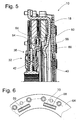
- FIGS. 5 and 6 show an alternative type of design, wherein here there are differences essentially in the configuration of the driver formation and the counter-driver formation. Therefore, in the following, essentially only the differences will be discussed.
- the remaining one Structure of the multi-plate clutch 10 corresponds to the above-described, so that reference can be made to this embodiment.
- driver formation 54 is realized on the cover disk element 40 again in its radially outer region by a plurality of axially bent driver projections 56. However, these are now bent away in the direction of the cover disk element 42 and thus extend in the direction of the pressure plate 18.
- FIGS. 7 and 8 show an embodiment variant in which the driver projections 56 in turn protrude axially from the cover disk element 40.
- the bend line about which the cam projections 56 are bent with respect to the body portion 72 of the cover disk member 40 does not extend approximately circumferentially or tangentially as in the previously described embodiments, but is substantially radial Direction, possibly with a peripheral inclination component extends.
- sections 82 are provided on the body region 72 radially outward, the first in the circumferential direction away extending and not further connected to the body portion 72 lobes, which are subsequently bent over the approximately radially extending bend line, so that the substantially axially extending driver projections 56 are obtained.
- driver projections 56 extending counter-Mit nowadaysaussparungen 70 are provided on the coupling element 64 of the friction lining assembly 50 with corresponding radial extent, ie, primarily from radially outside to radially inside, in which the Mit predominantlyvorsprünge 56 engage ,
- FIGS. 9 and 10 A modification to this is shown in FIGS. 9 and 10. It can be seen that the driver projections 56, which in turn are bent about an approximately radially extending bending line with respect to the body portion 72, are not provided on radially outward extensions of the body portion 72, but that by providing U-shaped punched-out portions initially in the circumferential direction extending tabs shown in phantom in Fig. 10, which are then bent to provide the approximately axially extending cam projections 56 from the plane of the body portion 72.
- FIGS. 11 and 12 show an embodiment variant in which the driver formation 54 provided on the cover disk element 40 is provided by driver projections 56, which are not extending substantially radially and are not bent relative to the body region 72.
- the counter-cam formation 66 is provided by a plurality of now axially bent counter-cam projections 68, between which the counter-cam recesses 70 which can also be seen in FIG. In this counter-engagement recesses 70 engage the radially outwardly extending driver projections 56th one.
- the driver projections 56 as shown in FIG.
- FIGS. 13 to 15 show a first such embodiment variant. It can be seen that on the cover disk element 40 or the disk-like body region 72 of the same in the radially outer region, ie radially outside the damper element arrangement 46, a plurality of driver projections 56 are defined as separate components in the circumferential direction successively. This can be done, for example, by welding on the driver projections 56 providing and approximately in the tangential and axial direction extending plate parts. In association with this, in the coupling element 64 of the friction lining assembly 50, a plurality of counter-engagement recesses 70 extending in the circumferential direction or tangential direction are again provided, in which the driving projections 56 engage axially. So here is basically one of the embodiment of FIGS. 5 and 6 created very similar arrangement, but in which the driver projections 56 do not form an integral part of the cover plate member 40, but are fixed thereto.
- the separately formed Mit psychologyvorsprünge 56 can not be fixed or not only by welding on the cover plate member 40, but that the connection can for example also be realized as the connection of the Mitprogressivelyvorsprünge 56 with the cover plate member 42 of FIG. 1 illustrated embodiment.
- FIGS. 16 and 17 Another alternative embodiment is shown in FIGS. 16 and 17.
- the driver formation 54 is not an integral part of one of the cover disk elements 40 or 42.
- a ring-like driver element 84 is provided, which is connected in the radially outer region with the cover disk elements 40, 42.
- the annular entrainment element 84 has at one axial end region projections 86 which pass through openings 88 in the cover disk element 42 and are shaped such that a form-fitting holding effect is achieved.
- the carrier arrangement 58 of the friction lining assembly 52 is fixed radially within this fixed connection between the cover disk element 42 and the driver element 84 on the cover disk element 42.
- the driver element 84 has the driver formation 54 in the form of a plurality of substantially axially extending driver projections 56. Between these driver projections 56 engage radially outwardly extending coupling projections 90 of the cover plate member 40, and that substantially without movement, so that, if necessary, even here an interference fit can be realized. In this way, a fixed support of the cover plate member 40 may be realized on the driver element 84.
- the driver projections 56 extend axially beyond the cover disk element 40 for coupling with the counter-driver formation 66 on the coupling element 64 of the friction lining assembly 50. It can be seen in FIG.
- this annular coupling element 64 is now arranged so as to be substantially lies radially within the annular carrier element 84 and the counter cam follower 66 extends with its counter-driver projections 68 substantially radially outward.
- both carrier assemblies 58, 62 may be configured substantially equal to each other, so that in the realization of the same as pad suspension also results in a substantially identical pad suspension behavior.
Abstract
Description
Die vorliegende Erfindung betrifft eine Kupplungsscheibenanordnung für eine Mehrscheibenkupplung, insbesondere eine Zweischeibenkupplung.The present invention relates to a clutch disk assembly for a multi-plate clutch, in particular a two-disc clutch.
In Antriebssträngen von Fahrzeugen mit vergleichsweise drehmomentenstarken Antriebsmotoren werden zunehmend zur Drehmomentübertragung zwischen dem Antriebsmotor und einem Getriebe so genannte Mehrscheibenkupplungen bzw. Zweischeibenkupplungen eingesetzt. Derartige Kupplungen haben den Vorteil, dass sie bei vorgegebener und durch einen Kraftspeicher, wie z.B. einer Membranfeder, gelieferter Einrückkraft aufgrund der Verdopplung (Vervielfachung) der Anzahl der Reibflächen auch wesentlich höhere Drehmomente übertragen können. Bei der Durchführung von Betätigungsvorgängen in derartigen Kupplungen ist es erforderlich, der Lüftbewegung einer Anpressplatte und einer oder mehrerer Zwischenplatten folgend auch die Reibbelagbaugruppen in Richtung einer Kupplungsdrehachse bezüglich einander verlagern zu können. Dies kann beispielsweise dadurch realisiert werden, dass die verschiedenen Reibbelagbaugruppen durch voneinander separat ausgebildete Kupplungsscheiben bereitgestellt werden, die für sich jeweils dann mit einer Abtriebswelle gekoppelt sind. Da dies einen vergleichsweise großen axialen Bauraum beansprucht, besteht allgemein die Tendenz, die Reibbelagbaugruppen über eine gemeinsame Nabe an eine Abtriebswelle anzubinden, bevorzugt über eine Torsionsschwingungsdämpferanordnung, um auch im Bereich der Kupplungsscheibenanordnung die Funktion einer Schwingungsdämpfung vorsehen zu können.In drive trains of vehicles with comparatively high-torque drive motors so-called multi-plate clutches or double-clutch clutches are increasingly used for torque transmission between the drive motor and a transmission. Such couplings have the advantage that they are at given and by a power storage, such as. a diaphragm spring, delivered engagement force due to the duplication (multiplication) of the number of friction surfaces can transmit much higher torques. When carrying out actuation processes in such couplings, it is necessary to be able to displace the friction movement of a pressure plate and one or more intermediate plates as well as the friction lining assemblies in the direction of a coupling axis of rotation with respect to each other. This can be realized, for example, by providing the various friction lining assemblies with clutch disks formed separately from each other, which are each then coupled to an output shaft. Since this requires a relatively large axial space, there is a general tendency to connect the friction lining assemblies via a common hub to an output shaft, preferably via a Torsionsschwingungsdämpferanordnung to provide the function of a vibration damping in the region of the clutch disk assembly can.
Es ist die Aufgabe der vorliegenden Erfindung, eine Kupplungsscheibenan ordnung für eine Mehrscheibenkupplung, insbesondere Zweischeibenkupplung, vorzusehen, bei welcher bei möglichst geringer axialer Baugröße in einfacher Art und Weise eine Axialrelativverlagerbarkeit der verschiedenen Reibbelagbaugruppen möglich ist.It is the object of the present invention to provide a clutch disk order for a multi-plate clutch, in particular two-disc clutch to provide, in which Axialrelativverlagerbarkeit the different friction lining assemblies is possible with the smallest possible axial size in a simple manner.
Erfindungsgemäß wird diese Aufgabe gelöst durch eine Kupplungsscheibenanordnung für eine Mehrscheibenkupplung, insbesondere Zweischeibenkupplung, umfassend eine Mehrzahl von Reibbelagbaugruppen, welche über eine Torsionsschwingungsdämpferanordnung mit einer Nabe verbunden sind, wobei die Torsionsschwingungsdämpferanordnung ein Zentralscheibenelement an der Nabe und beidseits davon Deckscheibenelemente umfasst, wobei die Deckscheibenelemente miteinander fest verbunden sind und über eine Dämpferelementenanordnung zur Drehmomentübertragung mit dem Zentralscheibenelement gekoppelt sind, wobei an wenigstens einem der Deckscheibenelemente eine Mitnehmerformation vorgesehen ist, mit welcher eine Gegen-Mitnehmerformation an wenigstens einer Reibbelagbaugruppe in eine Verschiebung dieser Reibbelagbaugruppe in Richtung einer Kupplungsscheibendrehachse zulassendem Drehkopplungseingriff steht.According to the invention this object is achieved by a clutch disk assembly for a multi-plate clutch, in particular double disc clutch, comprising a plurality of friction lining assemblies, which are connected via a Torsionsschwingungsdämpferanordnung with a hub, the Torsionsschwingungsdämpferanordnung comprises a central disk element on the hub and on both sides thereof cover disk elements, the cover disk elements fixed together are connected and are coupled via a damper element arrangement for transmitting torque to the central disk element, wherein on at least one of the cover disk elements, a driver formation is provided, with which a counter-driver on at least one friction lining assembly in a displacement of the friction lining assembly in the direction of a coupling disc rotation axis zulassendem Drehkopplungseingriff stands.
Durch das Bereitstellen der Mitnehmerformation im Bereich von wenigstens einem der Deckscheibenelemente übernimmt ein derartiges Deckscheibenelement neben seiner Funktion der Drehmomenteneinleitung in der Dämpferelementenanordnung auch noch die Funktion der axial beweglichen Drehankopplung zumindest einer der Reibbelagbaugruppen. Dies führt zu einem einfachen Aufbau bei vergleichsweise geringer axialer Bauhöhe.By providing the driver formation in the region of at least one of the cover disk elements, such a cover disk element also assumes the function of the axially movable rotary coupling of at least one of the friction lining assemblies in addition to its function of torque introduction in the damper element arrangement. This leads to a simple construction with a comparatively low axial height.
Um die Ausgestaltung noch weiter vereinfachen zu können, wird vorgeschlagen, dass die Mitnehmerformation mit einem Deckscheibenelement integral ausgebildet ist.In order to further simplify the design, it is proposed that the driver formation is formed integrally with a cover disk element.
Alternativ kann vorgesehen sein, dass die Mitnehmerformation von den Deckscheibenelementen getrennt ausgebildet und mit wenigstens einem der Deckscheibenelemente fest verbunden ist. Hierbei ist es möglich, dass die Mitnehmerformation mit dem wenigstens einen Deckscheibenelement durch materialschlüssige Verbindung, vorzugsweise Verschweißung, oder/und Umformung fest verbunden ist.Alternatively it can be provided that the driver formation of the Cover disk elements formed separately and is firmly connected to at least one of the cover disk elements. In this case, it is possible for the driver formation to be fixedly connected to the at least one cover disk element by means of material-locking connection, preferably welding, or / and deformation.
Die Drehkopplung zwischen Mitnehmerformation und Gegen-Mitnehmerformation kann beispielsweise in einfacher und zuverlässiger Weise dadurch generiert werden, dass die Mitnehmerformation eine Mehrzahl von Mitnehmervorsprüngen umfasst, die in Gegen-Mitnehmeraussparungen der Gegen-Mitnehmerformation eingreifen.The rotational coupling between driver formation and counter-driver formation can be generated, for example, in a simple and reliable manner in that the driver formation comprises a plurality of driver projections, which engage in counter-driver recesses of the counter driver configuration.
Die Mitnehmervorsprünge können sich im Wesentlichen axial erstrecken. Um dabei das Zusammenfügen der Mifnehmerformation mit der Gegen-Mitnehmerformation zu erleichtern, wird vorgeschlagen, dass die Mitnehmervorsprünge in wenigstens einem ihrer axialen Endbereiche sich verjüngend ausgebildet sind.The driver projections may extend substantially axially. In order to facilitate the joining of the Mifnehmerformation with the counter-driver formation, it is proposed that the driver projections are formed in at least one of its axial end portions are tapered.
Bei einer aus fertigungstechnischen Gründen besonders bevorzugten, da einfach zu realisierenden Ausgestaltungsform wird vorgeschlagen, dass die Mitnehmervorsprünge durch von einem scheibenförmigen Körperbereich eines Deckscheibenelements abgebogene Abschnitte gebildet sind. Dabei können die Abschnitte in Richtung auf das andere Deckscheibenelement zu gebogen sein und zur Erhöhung der Gesamtstabilität vorzugsweise auch in ihrem freien Endbereich an diesem festgelegt sein.In an embodiment which is particularly preferred for manufacturing reasons, because it is easy to implement, it is proposed that the driver projections are formed by sections bent from a disk-shaped body region of a cover disk element. In this case, the sections may be bent in the direction of the other cover disk element and preferably also be fixed in its free end region to increase the overall stability.
Um den fertigungstechnischen Aufwand bei der Herstellung insbesondere der Deckscheibenelement so gering als möglich zu halten, wird vorgeschlagen, dass die Mitnehmervorsprünge sich im Wesentlichen radial erstrecken und dass die Gegen-Mitnehmerformation im Wesentlichen axial sich erstreckende Gegen-Mitnehmervorsprünge umfasst, zwischen welchen die die Mitnehmervorsprünge aufnehmenden Gegen-Mitnehmeraussparungen vorgesehen sind. Dies minimiert die an dem Deckscheibenelement vorzunehmenden Umformungsvorgänge.In order to keep the manufacturing outlay on manufacture, in particular the cover disk element, as low as possible, it is proposed that the driver projections extend substantially radially and that the counter driver assembly comprises essentially axially extending counter driver projections between which the driver projections receive counter-Mitnehmeraussparungen are provided. This minimizes the forming operations to be performed on the shroud member.
Bei einer Ausgestaltungsform, bei welcher die Mitnehmerformation nicht als integraler Bestandteil von einem der Deckscheibenelemente ausgebildet ist, wird vorgeschlagen, dass ein Mitnehmerelement vorgesehen ist, das mit wenigstens einem Deckscheibenelement fest verbunden ist und an welchem die Mitnehmerformation ausgebildet ist.In an embodiment in which the driver formation is not formed as an integral part of one of the cover disk elements, it is proposed that a driver element is provided, which is firmly connected to at least one cover disk element and on which the driver formation is formed.
Um dabei eine stabile Anbindung an die Deckscheibenelemente zu erlangen, wird vorgeschlagen, dass das Mitnehmerelement ringartig ausgebildet ist und in einem ersten axialen Endbereich mit einem Deckscheibenelement fest verbunden ist und in einem zweiten axialen Endbereich die Mitnehmerformation aufweist. Weiterhin kann die Stabilität dadurch erhöht werden, dass das andere Deckscheibenelement Kopplungsvorsprünge aufweist, welche zwischen die Mitnehmervorsprünge an dem Mitnehmerelement eingreifen.In order to obtain a stable connection to the cover disk elements, it is proposed that the driver element is designed like a ring and is fixedly connected in a first axial end region with a cover disk element and has the driver formation in a second axial end region. Furthermore, the stability can be increased by the fact that the other cover disk element has coupling projections, which engage between the driver projections on the driver element.
Die wenigstens eine der Reibbelagbaugruppen, die über eine Gegen-Mitnehmerformation an die Torsionsschwingungsdämpferanordnung bzw. die Mitnehmerformation daran angebunden werden sollen, kann beispielsweise ein vorzugsweise ringförmiges Drehkopplungselement aufweisen, an welchem die Gegen-Mitnehmerformation vorgesehen ist und Reibbeläge über eine Trägeranordnung getragen sind.The at least one of the friction lining assemblies, which are to be connected to the torsional vibration damper arrangement or the driver formation thereon via a counter-driver formation, can, for example, have a preferably annular rotary coupling element, on which the counter-driver formation is provided and friction linings are carried by a carrier arrangement.
Vor allem dann, wenn eine derartige Trägeranrodnung als Belagfederung ausgebildet ist und es erstrebenswert ist, bei allen Reibbelagbaugruppen näherungsweise auch gleichartige Belagfederungen bereithalten zu können, wird vorgeschlagen, dass die Trägeranordnung mit dem Kopplungselement radial innerhalb eines Bereichs verbunden ist, in welchem der Drehkopplungseingriff der Mitnehmerformation mit der Gegen-Mitnehmerformation gebildet ist. Da es zum Bereitstellen der Axialrelativbewegbarkeit der Reibbelagbaugruppen nicht erforderlich ist, alle dieser Reibbelagbaugruppen auch axial bewegbar z. B. bezüglich der Torsionsschwingungsdämpferanordnung zu halten, wird vorgeschlagen, dass eine der Reibbelagbaugruppen mit einem Deckscheibenelement fest verbunden ist.Especially when such a Trägeranrodnung is designed as pad suspension and it is desirable to be able to hold approximately similar pad spring in all friction lining assemblies, it is proposed that the carrier assembly is connected to the coupling element radially within a range in which the Drehkopplungseingriff the Mitnehmerformation is formed with the counter-driver formation. Because it provides the axial relative movability of the friction lining assemblies is not required, all of these friction lining assemblies also axially movable z. B. with respect to the Torsionsschwingungsdämpferanordnung, it is proposed that one of the friction lining assemblies is firmly connected to a cover disk element.
Die Stabilität der erfindungsgemäßen Kupplungsscheibenanordnung insbesondere im Bereich der Torsionsschwingungsdämpferanordnung kann dadurch noch erhöht werden, dass die Deckscheibenelemente durch Verbindungsorgane miteinander fest verbunden sind. Dies bedeutet also, dass unabhängig davon, ob durch irgendwelche anderen Abschnitte, beispielsweise die Mitnehmerformation, eine feste Verbindung zwischen den Deckscheibenelementen realisiert ist, diese zusätzlich auch noch durch die Verbindungsorgane miteinander fest verbunden sind, die beispielsweise als Nietbolzen oder dergleichen ausgebildet sein können und im Allgemeinen dann in einem Bereich radial innerhalb der Mitnehmerformation liegen. Derartige Verbindungsorgane können gleichzeitig auch die Funktion einer Drehwinkelbegrenzung in Zusammenwirkung mit dem Zentralscheibenelement realisieren.The stability of the clutch disk arrangement according to the invention, in particular in the region of the torsional vibration damper arrangement, can be further increased by virtue of the fact that the cover disk elements are firmly connected to one another by connecting members. This means that regardless of whether by any other sections, such as the Mitnehmerformation, a firm connection between the cover plate elements is realized, these are additionally firmly connected to each other by the connecting members, which may be formed for example as a rivet bolt or the like and in Generally then lie in a region radially within the Mitnehmerformation. Such connecting members can simultaneously realize the function of a rotation angle limitation in cooperation with the central disk element.
Die vorliegende Erfindung betrifft ferner eine Mehrscheibenkupplung, insbesondere Zweischeibenkupplung mit einer erfindungsgemäßen Kupplungsscheibenanordnung und an einer ersten axialen Seite der Reibbelagbaugruppen einer Anpressplatte, an einer zweiten axialen Seite einer Widerlagerplatte und zwischen jeweils zwei Reibbelagbaugruppen einer Zwischenplatte.The present invention further relates to a multi-disc clutch, in particular two-disc clutch with a clutch disc assembly according to the invention and on a first axial side of the friction lining assemblies of a pressure plate, on a second axial side of an abutment plate and between each two friction lining assemblies of an intermediate plate.
Nachfolgend wir die Erfindung mit Bezug auf die beiliegenden Zeichnungen detailliert beschrieben. Es zeigt:
- Fig. 1
- eine Teil-Längsschnittansicht einer Mehrscheibenkupplung mit einer erfindungsgemäßen Kupplungsscheibenanordnung;
- Fig. 2
- eine Teil-Radialansicht eines eine Mitnehmerformation bereitstellenden Bereichs einer Torsionsschwingungsdämpferanordnung der Kupplungsscheibenanordnung in Fig. 1;
- Fig. 3
- eine perspektivische Teil-Ansicht einer Abwandlung der in Fig. 2 gezeigten Baugruppe;
- Fig. 4
- einen Rohling für ein Deckscheibenelement der in den Fig. 2 und 3 gezeigten Anordnungen;
- Fig. 5
- eine der Fig. 1 entsprechende Ansicht einer alternativen Ausgestaltungsart,
- Fig. 6
- eine Teil-Axialansicht, welche das Zusammenwirken einer Mitnehmerformation an einem Deckscheibenelement mit einer Gegen-Mitnehmerformation an einer Reibbelagbaugruppe darstellt;
- Fig. 7
- eine der Fig. 5 entsprechende Ansicht einer weiteren abgewandelten Ausgestaltungsart;
- Fig. 8
- eine Teil-Axialansicht, welche das Zusammenwirken einer Mitnehmerformation an einem Deckscheibenelement mit einer Gegen-Mitnehmerformation an einer Reibbelagbaugruppe darstellt;
- Fig. 9
- eine der Fig. 5 entsprechende Ansicht einer weiteren abgewandelten Ausgestaltungsart;
- Fig. 10
- eine Teil-Axialansicht eines Deckscheibenelements;
- Fig. 11
- eine der Fig. 5 entsprechende Ansicht einer weiteren abgewandelten Ausgestaltungsart;
- Fig. 12
- eine Teil-Axialansicht, welche das Zusammenwirken einer Mitnehmerformation an einem Deckscheibenelement mit einer Gegen-Mitnehmerformation an einer Reibbelagbaugruppe darstellt;
- Fig. 13
- eine der Fig. 5 entsprechende Ansicht einer weiteren abgewandelten Ausgestaltungsart;
- Fig. 14
- eine Teil-Axialansicht, welche das Zusammenwirken einer Mitnehmerformation an einem Deckscheibenelement mit einer Gegen-Mitnehmerformation an einer Reibbelagbaugruppe darstellt;
- Fig. 15
- die Anordnung der Fig. 14, geschnitten längs einer Linie XV-XV;
- Fig. 16
- eine Teil-Längsschnittansicht einer weiteren alternativen Ausgestaltüngsart;
- Fig. 17
- eine Teil-Radialansicht, welche den Eingriff einer Mitnehmerformation an der Torsionsschwingungsdämpferanordnung mit einer Gegen-Mitnehmerformation an einer Reibbelagbaugruppe darstellt.
- Fig. 1
- a partial longitudinal sectional view of a multi-plate clutch with a clutch disc assembly according to the invention;
- Fig. 2
- a partial radial view of a driver formation providing portion of a torsional vibration damper assembly of the clutch disk assembly in Fig. 1;
- Fig. 3
- a partial perspective view of a modification of the assembly shown in Figure 2;
- Fig. 4
- a blank for a cover plate member of the arrangements shown in Figures 2 and 3;
- Fig. 5
- 1 is a view corresponding to FIG. 1 of an alternative embodiment;
- Fig. 6
- a partial axial view illustrating the interaction of a driver formation on a cover plate member with a counter-cam formation on a friction lining assembly;
- Fig. 7
- one of Figure 5 corresponding view of another modified Ausgestaltungsart.
- Fig. 8
- a partial axial view illustrating the interaction of a driver formation on a cover plate member with a counter-cam formation on a friction lining assembly;
- Fig. 9
- one of Figure 5 corresponding view of another modified Ausgestaltungsart.
- Fig. 10
- a partial axial view of a cover plate member;
- Fig. 11
- one of Fig. 5 corresponding view of a further modified type of configuration;
- Fig. 12
- a partial axial view illustrating the interaction of a driver formation on a cover plate member with a counter-cam formation on a friction lining assembly;
- Fig. 13
- one of Figure 5 corresponding view of another modified Ausgestaltungsart.
- Fig. 14
- a partial axial view illustrating the interaction of a driver formation on a cover plate member with a counter-cam formation on a friction lining assembly;
- Fig. 15
- the arrangement of Figure 14, taken along a line XV-XV;
- Fig. 16
- a partial longitudinal sectional view of another alternative Ausgestaltüngsart;
- Fig. 17
- a partial radial view illustrating the engagement of a cam formation on the torsional vibration damper assembly with a counter-cam formation on a friction lining assembly.
In Fig. 1 ist eine im Antriebsstrang eines Kraftfahrzeugs einsetzbare Zweischeibenkupplung allgemein mit 10 bezeichnet. Diese Zweischenkupplung 10 umfasst eine Widerlagerplatte 12, beispielsweise in Form eines Schwungrads, Zwei-Massen-Schwungrads oder dergleichen, an der über eine Mehrzahl von Schraubbolzen 14 oder dergleichen ein im Wesentlichen topfartiges Gehäuse 16 festgelegt ist. In dem zwischen dem Gehäuse 16 und der Widerlagerplatte 12 gebildeten Raumbereich ist eine Anpressplatte 18 vorgesehen, die mit über das Gehäuse 16 nach radial außen hinaus greifenden Abschnitten 20 mit einem an der Außenseite des Gehäuses 16 angeordneten Kraftspeicher 22 zusammenwirkt. Der durch Distanzbolzen 24 am Gehäuse 16 abgestützte Kraftspeicher 22 beaufschlagt die Anpressplatte 18 in ihren Abschnitten 20 und presst sie somit in Richtung auf die Widerlagerplatte 12 zu. Zwischen der Anpressplatte 18 der Widerlagerplatte 12 liegt weiterhin eine Zwischenplatte 26. Auch diese greift mit Abschnitten 28 über das Gehäuse 16 nach radial außen und ist in diesen Bereichen 28 über Tangentialblattfedem oder dergleichen sowohl an die Anpressplatte 18 als auch die Widerlagerplatte 12 angekoppelt.In Fig. 1, a usable in the drive train of a motor vehicle dual-disc clutch is generally designated 10. This two-
Diese vorangehend beschriebenen Systemkomponenten Widerlagerplatte 12, Gehäuse 16, Kraftspeicher 22, Anpressplatte 20 und Zwischenplatte 28 bilden den wesentlichen Bereich eines an eine Antriebswelle, beispielsweise eine Kurbelwelle einer Brennkraftmaschine, anzukoppelnden Eingangsbereichs 30 der Zweischeibenkupplung 10.These system
Eine das in diesen Eingangsbereich 30 eingeleitete Drehmoment in Richtung zu einer Abtriebswelle, beispielsweise Getriebeeingangswelle, weiterleitende Kupplungsscheibenanordnung 32 umfasst in ihrem radial inneren Bereich eine Nabe 34. Diese ist mit einer Innenverzahnung ausgestattet und somit mit einer komplementären Verzahnung am Außenumfang einer Getriebeeingangswelle oder dergleichen zur gemeinsamen Rotation um eine Drehachse A koppelbar.A torque introduced into this
Eine Torsionsschwingungsdämpferanordnung 36 der Kupplungsscheibenanordnung 32 umfasst ein beispielsweise integral an der Nabe 34 vorgesehenes Zentralscheibenelement 38 und an beiden axialen Seiten davon jeweils ein Deckscheibenelement 40, 42. Diese beiden Deckscheibenelemente 40, 42 sind über eine Mehrzahl von in Umfangsrichtung verteilt angeordneten Bolzen 44 miteinander drehfest und axialfest verbunden. Sowohl im Zentralscheibenelement 38 als auch den Deckscheibenelementen 40, 42 sind beispielsweise durch so genannte Federfenster jeweils Abstützbereiche für die Dämpferelemente einer allgemein mit 46 bezeichneten Dämpferelementenanordnung vorgesehen. Diese Dämpferelemente, die beispielsweise als Schraubendruckfedern ausgeführt sein können, gestatten eine Relatiwerdrehbarkeit des Zentralscheibenelements 38 bezüglich der Deckscheibenelemente 40, 42 unter Kompression der Dämpferelemente, so dass im Rotationsbetrieb auftretende Drehungleichförmigkeiten aufgenommen werden können. Durch eine zwischen den Deckscheibenelementen 40, 42 und dem Zentralscheibenelement 38 wirkende Reibanordnung 48 kann bei Auftreten von Drehungleichförmigkeiten kinetische Energie in Wärme umgewandelt werden und somit dissipiert werden. Eine Relativbewegung des Zentralscheibenelements 38 bezüglich der Deckscheibenelemente 40, 42 ist durch das Zusammenwirken der radial äußeren Bereiche des Zentralscheibenelements 38 mit den Bolzen 44 begrenzt, so dass eine Überlastung der Dämpferelemente der Dämpferelementenanordnung 46 nicht auftreten kann.A
Die Kupplungsscheibenanordnung 32 dieser Zweischeibenkupplung 10 umfasst zwei Reibbelagbaugruppen 50, 52. Jede dieser Reibbelagbaugruppen 50, 52 umfasst in ihrem radial äußeren Bereich Reibbeläge 53, 55, wobei die Reibbeläge 53 der Reibbelagbaugruppe 50 zwischen der Anpressplatte 18 und der Zwischenplatte 26 liegen, während die Reibbeläge 55 der Reibbelagbaugruppe 52 zwischen der Zwischenplatte 26 und der Widerlagerplatte 12 liegen. Die Reibbeläge 55 der Reibbelagbaugruppe 52 sind über eine Trägeranordnung 58, die beispielsweise durch eine Belagfederung bereitgestellt sein kann, mit dem radial äußeren Bereich des Deckscheibenelements 42 durch Vernietung fest verbunden. Auf diese Art und Weise ist die Reibbelagbaugruppe 52 mit der Torsionsschwingungsdämpferanordnung 36 und auch der Nabe 34 nicht nur drehfest gekoppelt, sondern auch axial fest verbunden.Each of these
Da zum Ausrücken der Zweischeibenkupplung 10 es grundsätzlich nicht nur erforderlich ist, die Apressplatte 18 und die Zwischenplatte 26 voneinander weg zu bewegen und auch die Zwischenplatte 26 von der Widerlagerplatte 12 weg zu bewegen, sondern es weiterhin erforderlich ist, eine axiale Relativbewegung zwischen den beiden Reibbelagbaugruppen 50, 52 zu ermöglichen, um den Reibeingriff der Reibbeläge 53 und 55 mit der Zwischenplatte 26 aufheben oder mindern zu können, ist die Reibbelagbaugruppe 50 nicht axial fest an die Torsionsschwingungsdämpferanordnung 36 angebunden. Vielmehr ist, wie im Folgenden dargelegt, dafür gesorgt, dass zwar eine drehfeste Ankopplung dieser Reibbelagbaugruppe 50 an die Torsionsschwingungsdämpferanordnung 36 und über diese an die Nabe 34 realisiert ist, dass jedoch die Reibbelagbaugruppe 50 axial bezüglich der Torsionsschwingungsdämpferanordnung 36 und somit auch der damit fest verbundenen Reibbelagbaugruppe 52 verschoben werden kann.In principle, not only is it necessary to move the
Um dies zu realisieren, ist an der Torsionsschwingungsdämpferanordnung 36 bzw. dem Deckscheibenelement 40 eine Mitnehmerformation 54 vorgesehen. Diese umfasst, wie auch in der Darstellung der Fig. 2 erkennbar, am radial äußeren Bereich des Deckscheibenelements 40 eine Mehrzahl von in Umfangsrichtung mit gegenseitigem Abstand zueinander angeordneten und axial abgebogenen Mitnehmervorsprüngen 56. Diese Mitnehmervorsprünge 56 erstrecken sich auf das andere Deckscheibenelement 42 zu und überbrücken somit das Zentralscheibenelement 38 an seiner radialen Außenseite. Im Bereich ihrer freien Enden weisen die Mitnehmervorsprünge 56 Verbindungsabschnitte 58 auf, welche zugehörige Öffnungen 60 im anderen Deckscheibenelement 42 durchsetzen und durch Verstemmen so verformt sind, dass eine feste formschlüssige Verbindung zwischen den Mitnehmervorsprüngen 56 und dem Deckscheibenelement 42 realisiert ist, wobei diese feste, formschlüssige Verbindung in einem Bereich radial innerhalb der Verbindung des Deckscheibenelements 42 mit der Trägeranordnung 58 der Reibbelagbaugruppe 52 angeordnet ist.In order to realize this, a
Die Reibbelagbaugruppe 50 weist, ähnlich wie die Reibbelagbaugruppe 52, eine Trägeranordnung 62, beispielsweise wiederum in Form einer Belagfederung auf, die mit einem ringartigen Kopplungselement 64 beispielsweise durch Vernietung fest verbunden ist. Dieses ringartige Kopplungselement 64 ist grundsätzlich derartig dimensioniert und positioniert, dass es das Deckscheibenelement 40 an seiner radialen Außenseite umgibt. An dem Kopplungselement 64 ist eine Gegen-Mitnehmerformation 66 vorgesehen, die eine Mehrzahl von sich im Wesentlichen nach radial innen erstreckenden Gegen-Mitnehmervorsprüngen 68 mit dazwischen liegenden Gegen-Mitnehmeraussparungen 70 bildet. Man erkennt in Fig. 2, dass die Mitnehmervorsprünge 56 und die Gegen-Mitnehmervorsprünge 58 miteinander eingreifen, so dass die Mitnehmervorsprünge 56 in den Gegen-Mitnehmeraussparungen 70 zu liegen kommen. Dabei ist vorzugsweise dieser Eingriff möglichst spielfrei. Da die Mitnehmervorsprünge 56 sich in axialer Richtung erstreckend ausgebildet sind, ist auf diese Art und Weise auch bei hergestelltem Drehkopplungseingriff zwischen der Mitnehmerformation 54 und der Gegen-Mitnehmerformation 66 eine Axialbewegbarkeit der Reibbelagbaugruppe 50 realisiert.The
Um das Zusammenfügen der Kupplungsscheibenanordnung 32 zu erleichtern, ist es beispielsweise möglich, wie durch strichlierte Linien in Fig. 2 angedeutet, die Mitnehmervorsprünge 56 in einem ihrer axialen Endbereiche sich verjüngend auszubilden, um somit Einführschrägen für die Gegen-Mitnehmervorsprünge 68 vorzusehen. Weiterhin ist in demjenigen Bereich, in welchem die Gegen-Mitnehmervorsprünge 56 an den scheibenartigen Körperbereich 72 des Deckscheibenelements 40 anschließen, durch entsprechende Abkrümmung dafür gesorgt, dass die zwischen den Mitnehmervorsprüngen 56 gebildeten Aussparungen 74 sich so weit nach radial innen erstrecken, dass die Gegen-Mitnehmerformation 66 axial aufgeschoben werden kann. Weiterhin erkennt man in Fig. 1, dass in seinem radial äußeren Bereich der Körperbereich 72 des Deckscheibenelements 40 bzw. die Mitnehmervorsprünge 56 zunächst axial in Richtung von dem anderen Deckscheibenelement 42 weg gekrümmt und erst dann in Richtung auf dieses zu gekrümmt sind. Auf diese Art und Weise kann die axiale Erstreckungslänge zur verbesserten Wechselwirkung der Reibbelagbaugruppe 50 mit dem Deckscheibenelement 40 verlärigert werden.In order to facilitate the assembly of the
Eine Abwandlung hierzu ist in Fig. 3 dargestellt. Man erkennt den radial äußeren Bereich der Deckscheibenelemente 40, 42 und die vom Deckscheibenelement 40 axial abgebogenen Mitnehmervorsprünge 56. Diese sind in einem in Umfangsrichtung zentralen Abschnitt 76 an den Körperbereich 72 des Deckscheibenelements 40 materialschlüssig bzw. integral angebunden und weisen beidseits dieses auch gekrümmt verlaufenden Abschnitts 76 sich im Wesentlichen geradlinig axial erstreckende Abschnitte 78, 80 auf, welche die Wechselwirkungslänge für die Gegen-Mitriehmerformation 60 in axialer Richtung deutlich verlängern.A modification to this is shown in Fig. 3. It can be seen the radially outer region of the
In Fig. 4 ist ein Rohling für ein derartiges Deckscheibenelement 40 dargestellt, wobei in der linken Hälfte der Fig. 4 ein Rohling für die Ausgestaltungsvariante gemäß Fig. 2 gezeigt ist, während in der rechten Hälfte ein Rohling für die Ausgestaltungsvariante gemäß Fig. 3 gezeigt ist. Man erkennt in dem Körperbereich 72 eines der Federfenster 80 für die Dämpferelementenanordnung 46, und man erkennt die in dem Rohling sich noch nach radial außen erstreckenden Mitnehmervorsprünge 56. Dieser Rohling kann durch ausschneiden oder ausstanzen aus Blechmaterial erhalten werden und dann durch Biegen in die in Fig. 2 bzw. Fig. 3 gezeigte Form gebracht werden. Man erkennt weiter in Fig. 4 durch Strichlinie jeweils eine alternative Führung der Außenumfangskontur zum Bereitstellen der sich in axialer Richtung verjüngenden Mitnehmervorsprünge 56.In Fig. 4, a blank for such a
Die Fig. 5 und 6 zeigen eine alternative Ausgestaltungsart, wobei hier Unterschiede im Wesentlichen in der Ausgestaltung der Mitnehmerformation und der Gegen-Mitnehmerformation bestehen. Es wird daher im Folgenden im Wesentlichen auch nur auf die Unterschiede eingegangen. Der verbleibende Aufbau der Mehrscheibenkupplung 10 entspricht dem vorangehend Beschriebenen, so dass auf diese Ausführung verwiesen werden kann.FIGS. 5 and 6 show an alternative type of design, wherein here there are differences essentially in the configuration of the driver formation and the counter-driver formation. Therefore, in the following, essentially only the differences will be discussed. The remaining one Structure of the multi-plate clutch 10 corresponds to the above-described, so that reference can be made to this embodiment.
Man erkennt in Fig. 5, dass an dem Deckscheibenelement 40 wieder in seinem radial äußeren Bereich die Mitnehmerformation 54 durch eine Mehrzahl von axial abgebogenen Mitnehmervorsprüngen 56 realisiert ist. Diese sind jedoch nunmehr in Richtung vom Deckscheibenelement 42 weg gebogen und erstrecken sich somit in Richtung auf die Anpressplatte 18 zu.It can be seen in FIG. 5 that the
In dem Kopplungselement 64 der Reibbelagbaugruppe 50 sind an den axial abgebogenen Mitnehmervorsprüngen 56 entsprechenden Umfangspositionen langlochartig die Gegen-Mitnehmeraussparungen 70 ausgebildet, in welche die Mitnehmervorsprünge 56 mit möglichst geringem Bewegungsspiel eingreifen.In the
Auch hier ist also in einfacher Art und Weise eine Axialbewegbarkeit der Reibbelagbaugruppe 50 bezüglich der Torsionsschwingungsdämpferanordnung 36 der Kupplungsscheibenanordnung 32 realisiert, wobei gleichzeitig durch Zusammenwirken der Mitnehmervorsprünge 56 mit den Gegen-Mitnehmeraussparungen 70 eine Umfangs- bzw. Radialzentrierung der Reibbelagbaugruppe 50 realisiert ist.Here, too, axial mobility of the
In den Fig. 7 und 8 ist eine Ausgestaltungsvariante gezeigt, bei welcher die Mitnehmervorsprünge 56 wiederum axial vom Deckscheibenelement 40 abstehen. Ein Unterschied besteht nunmehr darin, dass die Biegelinie, um welche die Mitnehmervorsprünge 56 bezüglich des Körperbereichs 72 des Deckscheibenelements 40 abgebogen bzw. gekrümmt sind, sich nicht, wie in den vorangehend beschriebenen Ausgestaltungsformen näherungsweise in Umfangsrichtung oder tangential erstreckt, sondern sich im Wesentlichen in radialer Richtung, ggf. auch mit einer Umfangsneigungskomponente, erstreckt. Hierzu sind, wie der Darstellung der Fig. 8 zu entnehmen, an den Körperbereich 72 nach radial außen anschließend Abschnitte 82 vorgesehen, die zunächst in Umfangsrichtung sich weg erstreckende und nicht weiter an den Körperbereich 72 angebundene Lappen aufweisen, welche nachfolgend um die näherungsweise in radialer Richtung sich erstreckende Biegelinie umgebogen werden, so dass die sich im Wesentlichen axial erstreckenden Mitnehmervorsprünge 56 erhalten werden. In Zuordnung zu diesen sich auch von radial innen nach radial außen erstreckenden Mitnehmervorsprüngen 56 sind an dem Kopplungselement 64 der Reibbelagbaugruppe 50 mit entsprechender Radialerstreckung, also primär von radial außen nach radial innen, sich erstreckende Gegen-Mitnehmeraussparungen 70 vorgesehen, in welche die Mitnehmervorsprünge 56 eingreifen.FIGS. 7 and 8 show an embodiment variant in which the
Eine Abwandlung hierzu ist in den Fig. 9 und 10 dargestellt. Man erkennt, dass die Mitnehmervorsprünge 56, die wiederum um eine näherungsweise radial sich erstreckende Biegelinie bezüglich des Körperbereichs 72 abgebogen sind, nicht an nach radial außen liegenden Verlängerungen des Körperbereichs 72 vorgesehen sind, sondern dass durch Bereitstellen U-förmiger Ausstanzungen die zunächst in Umfangsrichtung sich erstreckenden und in Fig. 10 mit Strichlinie eingezeichneten Lappen vorhanden sind, die dann zum Bereitstellen der näherungsweise axial sich erstreckenden Mitnehmervorsprünge 56 aus der Ebene des Körperbereichs 72 herausgebogen werden.A modification to this is shown in FIGS. 9 and 10. It can be seen that the
In den Fig. 11 und 12 ist eine Ausgestaltungsvariate gezeigt, bei welcher die am Deckscheibenelement 40 vorgesehene Mitnehmerformation 54 durch sich im Wesentlichen radial erstreckende und bezüglich des Körperbereichs 72 nicht abgebogene Mitnehmervorsprünge 56 bereitgestellt ist. In entsprechender Weise ist am Kopplungselement 64 der Reibbelagbaugruppe 50 radial innen die Gegen-Mitnehmerformation 66 durch eine Mehrzahl von nunmehr axial abgebogenen Gegen-Mitnehmervorsprüngen 68 bereitgestellt, zwischen welchen die in Fig. 12 auch erkennbaren Gegen-Mitnehmeraussparungen 70 gebildet sind. In diese Gegen-Mitnehmeraussparungen 70 greifen die nach radial außen sich erstreckenden Mitnehmervorsprünge 56 ein. Dabei sind vorzugsweise die Mitnehmervorsprünge 56, so wie in Fig. 12 dargestellt, in Richtung nach radial außen und in Umfangsrichtung sich erweiternd ausgebildet, um einen stabilen Eingriff mit den Gegen-Mitnehmervorsprüngen 68 zu erlangen. Ferner ist durch die Wechselwirkung der Mitnehmerformation 54 mit der Gegen-Mitnehmerformation 66 auch für eine Zentrierung der Reibbelagbaugruppe 50 gesorgt.FIGS. 11 and 12 show an embodiment variant in which the
Vorangehend sind Ausgestaltungsformen beschrieben worden, bei welchen die an der Torsionsschwingungsdämpferanordnung vorgesehene Mitnehmerformation durch entsprechende Formgebung und Ausgestaltung von einem der Deckscheibenelemente bereitgestellt ist. Nachfolgend werden Ausgestaltungsformen beschrieben, bei welchen diese Mitnehmerformation zwar weiterhin im Bereich der oder von einem der Deckscheibenelemente vorgesehen ist, jedoch durch eine separate Baugruppe realisiert ist, die dann an zumindest einem dieser Deckscheibenelemente festgelegt ist.Previously, embodiments have been described in which the driver formation provided on the torsional vibration damper arrangement is provided by appropriate shaping and design of one of the cover disk elements. Embodiments will be described below in which this driver formation is still provided in the region of or from one of the cover disk elements, but is realized by a separate assembly, which is then fixed to at least one of these cover disk elements.
In den Fig. 13 bis 15 ist eine erste derartige Ausgestaltungsvariante dargestellt. Man erkennt, dass an dem Deckscheibenelement 40 bzw. dem scheibenartigen Körperbereich 72 desselben im radial äußeren Bereich, also radial außerhalb der Dämpferelementenanordnung 46, in Umfangsrichtung aufeinander folgend mehrere Mitnehmervorsprünge 56 als separate Bauteile festgelegt sind. Dies kann beispielsweise durch Anschweißen von die Mitnehmervorsprünge 56 bereitstellenden und sich näherungsweise in tangentialer und axialer Richtung erstreckenden Plattenteilen erfolgen. In Zuordnung dazu ist in dem Kopplungselement 64 der Reibbelagbaugruppe 50 wieder eine Mehrzahl von in Umfangsrichtung bzw. tangentialer Richtung sich erstreckenden Gegen-Mitnehmeraussparungen 70 vorgesehen, in welche die Mitnehmervorsprünge 56 axial eingreifen. Hier ist also grundsätzlich eine der Ausgestaltungsform der Fig. 5 und 6 sehr ähnliche Anordnung geschaffen, bei der jedoch die Mitnehmervorsprünge 56 keinen integralen Bestandteil des Deckscheibenelements 40 bilden, sondern daran festgelegt sind.FIGS. 13 to 15 show a first such embodiment variant. It can be seen that on the
Es sei darauf hingewiesen, dass selbstverständlich die separat ausgebildeten Mitnehmervorsprünge 56 nicht oder nicht nur durch Verschweißung am Deckscheibenelement 40 festgelegt werden können, sondern dass die Verbindung beispielsweise auch so realisiert sein kann, wie die Verbindung der Mitnehmervorsprünge 56 mit dem Deckscheibenelement 42 der in Fig. 1 dargestellten Ausgestaltungsform.It should be noted that, of course, the separately formed
Eine weitere alternative Ausgestaltungsform ist in den Fig. 16 und 17 gezeigt. Hier ist wiederum dafür gesorgt, dass die Mitnehmerformation 54 nicht integraler Bestandteil von einem der Deckscheibenelemente 40 oder 42 ist. Vielmehr ist ein ringartiges Mitnehmerelement 84 vorgesehen, das im radial äußeren Bereich mit den Deckscheibenelementen 40, 42 verbunden ist. Hierzu weist das ringartige Mitnehmerelement 84 an einem axialen Endbereich Vorsprünge 86 auf, die Öffnungen 88 im Deckscheibenelement 42 durchsetzen und umgeformt sind, dass eine formschlüssige Halterungswirkung erlangt ist. Man erkennt dabei in den Fig. 16 und 17, dass die Trägeranordnung 58 der Reibbelagbaugruppe 52 radial innerhalb dieser festen Verbindung zwischen dem Deckscheibenelement 42 und dem Mitnehmerelement 84 an dem Deckscheibenelement 42 festgelegt ist. In dem anderen axialen Endbereich weist das Mitnehmerelement 84 die Mitnehmerformation 54 in Form mehrerer sich im Wesentlichen axial erstreckender Mitnehmervorsprünge 56 auf. Zwischen diese Mitnehmervorsprünge 56 greifen nach radial außen sich erstreckende Kopplungsvorsprünge 90 des Deckscheibenelements 40 ein, und zwar im Wesentlichen ohne Bewegungsspiel, so dass ggf. hier sogar eine Presspassung realisiert sein kann. Auf diese Art und Weise kann auch eine feste Halterung des Deckscheibenelements 40 an dem Mitnehmerelement 84 realisiert sein. Die Mitnehmervorsprünge 56 erstrecken sich über das Deckscheibenelement 40 axial hinaus zur Kopplung mit der Gegen-Mitnehmerformation 66 an dem Kopplungselement 64 der Reibbelagbaugruppe 50. Man erkennt in Fig. 16, dass dieses ringartige Kopplungselement 64 nunmehr so angeordnet ist, dass es im Wesentlichen radial innerhalb des ringartigen Mitnehmerelements 84 liegt und die Gegen-Mitnehmerformation 66 mit ihren Gegen-Mitehmervorsprüngen 68 sich im Wesentlichen nach radial außen erstreckt. Auf diese Art und Weise ist dafür gesorgt, dass die feste Verbindung der Trägeranordnung 62 der Reibbeläge 53 der Reibbelagbaugruppe 50 mit dem Kopplungselement 64 in einem radialen Bereich erfolgt, in dem auch die Trägeranordnung 58 mit dem Deckscheibenelement 42 verbunden ist. Das heißt, beide Trägeranordnungen 58, 62 können im Wesentlichen zueinander gleich ausgestaltet sein, so dass sich bei Realisierung derselben als Belagfederung auch ein im Wesentlichen gleiches Belagfederungsverhalten ergibt. Es ist selbstverständlich, dass eine derartige Ausgestaltung der Reibbelagbaugruppe 50, bei welcher die Verbindung der Trägeranordnung mit dem Kopplungselement radial innerhalb desjenigen Bereichs angeordnet ist, in welchem die Drehkopplungsverbindung zwischen der Mitnehmerformation 54 und der Gegen-Mitnehmerformation 66 realisiert ist, auch bei den anderen vorangehend beschriebenen Ausgestaltungsformen realisiert sein kann.Another alternative embodiment is shown in FIGS. 16 and 17. Here again, it is ensured that the
Claims (19)
dadurch gekennzeichnet, dass die Mitnehmerformation (54) mit einem Deckscheibenelement (40) integral ausgebildet ist.Clutch disc assembly according to claim 1,
characterized in that the driver formation (54) is integrally formed with a cover disk element (40).
dadurch gekennzeichnet, dass die Mitnehmerformation (54) von den Deckscheibenelementen (40, 42) getrennt ausgebildet und mit wenigstens einem der Deckscheibenelemente (40, 42) fest verbunden ist.Clutch disc assembly according to claim 1,
characterized in that the driver formation (54) of the cover disk elements (40, 42) is formed separately and fixedly connected to at least one of the cover disk elements (40, 42).
dadurch gekennzeichnet, dass die Mitnehmerformation (54) mit dem wenigstens einen Deckscheibenelement (50, 52) durch materialschlüssige Verbindung, vorzugsweise Verschweißung, oder/und Umformung fest verbunden ist.Clutch disc assembly according to claim 3,
characterized in that the driver formation (54) with the at least one cover disk element (50, 52) by material connection, preferably welding, and / or forming is firmly connected.
dadurch gekennzeichnet, dass die Mitnehmerformation (54) eine Mehrzahl von Mitnehmervorsprüngen (56) umfasst, die in Gegen-Mitnehmeraussparungen (70) der Gegen-Mitnehmerformation (66) eingreifen.Clutch disc arrangement according to one of claims 1 to 4,
characterized in that the cam formation (54) comprises a plurality of cam projections (56) which engage in counter-engagement recesses (70) of the counter cam formation (66).
dadurch gekennzeichnet, dass die Mitnehmervorsprünge (54) sich im Wesentlichen axial erstrecken.Clutch disc assembly according to claim 5,
characterized in that the driver projections (54) extend substantially axially.
dadurch gekennzeichnet, dass die Mitnehmervorsprünge (54) in wenigstens einem ihrer axialen Endbereiche sich verjüngend ausgebildet sind.Clutch disc assembly according to claim 6,
characterized in that the driver projections (54) are tapered in at least one of their axial end regions.
dadurch gekennzeichnet, dass die Mitnehmervorsprünge durch von einem scheibenförmigen Körperbereich (72) eines Deckscheibenelements (40) abgebogene Abschnitte gebildet sind.Clutch disc assembly according to claim 2 and claim 6 or 7,
characterized in that the driver projections are formed by portions bent from a disk-shaped body region (72) of a cover disk element (40).
dadurch gekennzeichnet, dass die Abschnitte in Richtung auf das andere Deckscheibenelement (42) zu gebogen sind.Clutch disc assembly according to claim 8,
characterized in that the sections are bent in the direction of the other cover disk element (42).
dadurch gekennzeichnet, dass die Abschnitte mit ihrem freien Endbereich an dem anderen Deckscheibenelement (42) festgelegt sind.Clutch disc assembly according to claim 9,
characterized in that the sections are fixed with their free end region on the other cover disk element (42).
dadurch gekennzeichnet, dass die Mitnehmervorsprünge (56) sich im Wesentlichen radial erstrecken und dass die Gegen-Mitnehmerformation (66) im Wesentlichen axial sich erstreckende Gegen-Mitnehmervorsprünge (68) umfasst, zwischen welchen die die Mitnehmervorsprünge (56) aufnehmenden Gegen-Mitnehmeraussparungen (70) vorgesehen sind.Clutch disc assembly according to claim 5,
characterized in that the driver projections (56) are in Extend substantially radially and that the counter-cam formation (66) comprises substantially axially extending counter-cam projections (68), between which the the cam projections (56) receiving counter-cam recesses (70) are provided.
dadurch gekennzeichnet, dass ein Mitnehmerelement (84) vorgesehen ist, das mit wenigstens einem Deckscheibenelement (40, 42) fest verbunden ist und an welchem die Mitnehmerformation (54), ausgebildet ist.Clutch disc assembly according to claim 3 or any one of claims 4 to 7, when dependent on claim 3,
characterized in that a driver element (84) is provided, which is fixedly connected to at least one cover disk element (40, 42) and on which the driver formation (54) is formed.
dadurch gekennzeichnet, dass das Mitnehmerelement (84) ringartig ausgebildet ist und in einem ersten axialen Endbereich mit einem Deckscheibenelement (42) fest verbunden ist und in einem zweiten axialen Endbereich die Mitnehmerformation (54) aufweist.Clutch disc assembly according to claim 12,
characterized in that the driver element (84) is of annular design and in a first axial end region with a cover disk element (42) is fixedly connected and in a second axial end region of the driver formation (54).
dadurch gekennzeichnet, dass das andere Deckscheibenelement (40) Kopplungsvorsprünge (90) aufweist, welche zwischen die Mitnehmervorsprünge (56) an dem Mitnehmerelement (84) eingreifen.Clutch disc assembly according to claim 5 and claim 13,
characterized in that the other cover disc element (40) has coupling projections (90) which engage between the driver projections (56) on the driver element (84).
dadurch gekennzeichnet, dass die wenigstens eine Reibbelagbaugruppe (50) ein ringartiges Kopplungselement (64) aufweist, an welchem die Gegen-Mitnehmerformation (66) vorgesehen ist und Reibbeläge (53) über eine Trägeranordnung (62) getragen sind.Clutch disc arrangement according to one of claims 1 to 14,
characterized in that the at least one friction lining assembly (50) comprises a ring-like coupling element (64) on which the counter-cam formation (66) is provided and friction linings (53) via a support assembly (62) are supported.
dadurch gekennzeichnet, dass die Trägeranordnung (62) mit dem Kopplungselement (64) radial innerhalb eines Bereichs verbunden ist, in welchem der Drehkopplungseingriff der Mitnehmerformation (54) mit der Gegen-Mitnehmerformation (66) gebildet ist.Clutch disc assembly according to claim 15,
characterized in that the carrier assembly (62) with the Coupling element (64) is connected radially within a range in which the Drehkopplungseingriff the cam formation (54) with the counter-cam formation (66) is formed.
dadurch gekennzeichnet, dass eine der Reibbelagbaugruppen (50, 52) mit einem Deckscheibenelement (42) fest verbunden ist.Clutch disc arrangement according to one of claims 1 to 16,
characterized in that one of the friction lining assemblies (50, 52) is fixedly connected to a cover disk element (42).
dadurch gekennzeichnet, dass die Deckscheibenelemente (40, 42) durch Verbindungsorgane (44) miteinander fest verbunden sind.Clutch disc arrangement according to one of claims 1 to 17,
characterized in that the cover disk elements (40, 42) by connecting members (44) are fixedly connected to each other.
Applications Claiming Priority (1)
| Application Number | Priority Date | Filing Date | Title |
|---|---|---|---|
| DE102005021344 | 2005-05-04 |
Publications (3)
| Publication Number | Publication Date |
|---|---|
| EP1719930A2 true EP1719930A2 (en) | 2006-11-08 |
| EP1719930A3 EP1719930A3 (en) | 2007-05-30 |
| EP1719930B1 EP1719930B1 (en) | 2010-01-27 |
Family
ID=36649737
Family Applications (1)
| Application Number | Title | Priority Date | Filing Date |
|---|---|---|---|
| EP06008476A Not-in-force EP1719930B1 (en) | 2005-05-04 | 2006-04-25 | Clutch plate assembly for multiple disc clutch, especially twin-plate clutch |
Country Status (4)
| Country | Link |
|---|---|
| US (1) | US7650975B2 (en) |
| EP (1) | EP1719930B1 (en) |
| AT (1) | ATE456750T1 (en) |
| DE (1) | DE502006006020D1 (en) |
Cited By (2)
| Publication number | Priority date | Publication date | Assignee | Title |
|---|---|---|---|---|
| EP1729024A3 (en) * | 2005-06-04 | 2009-04-15 | Zf Friedrichshafen Ag | Hub and clutch disc arrangement for a friction clutch, in particular a multi-disc clutch |
| WO2013088211A1 (en) * | 2011-12-14 | 2013-06-20 | Eaton Corporation | Series damper for single and twin friction plate hd clutch |
Families Citing this family (1)
| Publication number | Priority date | Publication date | Assignee | Title |
|---|---|---|---|---|
| US8430222B2 (en) * | 2009-11-02 | 2013-04-30 | Tnmj Caliber, Llc | Friction clutch system |
Family Cites Families (4)
| Publication number | Priority date | Publication date | Assignee | Title |
|---|---|---|---|---|
| FR2411999A2 (en) * | 1977-02-25 | 1979-07-13 | Ferodo Sa | DAMPER HUB CLUTCH FRICTION FOR MOTOR VEHICLE |
| US5501310A (en) * | 1993-08-20 | 1996-03-26 | Kabushiki Kaisha Daikin Seisakusho | Motorcycle clutch device |
| JP3518959B2 (en) * | 1996-09-25 | 2004-04-12 | 株式会社エクセディ | Twin clutch |
| GB0009514D0 (en) * | 1999-05-19 | 2000-06-07 | Mannesmann Sachs Ag | Clutch disc arrangement for a multiple disc clutch |
-
2006
- 2006-04-25 EP EP06008476A patent/EP1719930B1/en not_active Not-in-force
- 2006-04-25 DE DE502006006020T patent/DE502006006020D1/en active Active
- 2006-04-25 AT AT06008476T patent/ATE456750T1/en active
- 2006-05-03 US US11/416,746 patent/US7650975B2/en not_active Expired - Fee Related
Non-Patent Citations (1)
| Title |
|---|
| None |
Cited By (2)
| Publication number | Priority date | Publication date | Assignee | Title |
|---|---|---|---|---|
| EP1729024A3 (en) * | 2005-06-04 | 2009-04-15 | Zf Friedrichshafen Ag | Hub and clutch disc arrangement for a friction clutch, in particular a multi-disc clutch |
| WO2013088211A1 (en) * | 2011-12-14 | 2013-06-20 | Eaton Corporation | Series damper for single and twin friction plate hd clutch |
Also Published As
| Publication number | Publication date |
|---|---|
| EP1719930B1 (en) | 2010-01-27 |
| DE502006006020D1 (en) | 2010-03-18 |
| EP1719930A3 (en) | 2007-05-30 |
| US7650975B2 (en) | 2010-01-26 |
| ATE456750T1 (en) | 2010-02-15 |
| US20060249347A1 (en) | 2006-11-09 |
Similar Documents
| Publication | Publication Date | Title |
|---|---|---|
| EP2387674B1 (en) | Multiple clutch device | |
| EP1693588B1 (en) | Arrangement for axially supporting two rotating elements. | |
| EP1862689B2 (en) | Torque transmission assembly for the power transmission of a vehicle | |
| DE19802251B4 (en) | wrap spring | |
| WO2012110018A1 (en) | Torque transmitting device | |
| EP3449145A1 (en) | Clutch with torque flow distribution for partial boosting | |
| WO2021228303A1 (en) | Multi-disc clutch assembly having independently acting spring plate units for connecting two component discs to an output shaft | |
| EP2340378A1 (en) | Torsional vibration damping arrangement, particularly for the power train of a vehicle | |
| DE10156041B4 (en) | Hydrodynamic coupling device | |
| WO2015120845A1 (en) | Normally-engaged clutch device | |
| EP2347145B1 (en) | Torsional vibration damper for the drive train of a vehicle | |
| DE10024088A1 (en) | Automotive clutch separates lining from clutch plate function, simplifying construction and optimizing design function | |
| DE102011100864A1 (en) | Friction clutch device, particularly for internal combustion engine driven motor vehicle, has inlet part provided with clutch plate, where outlet part is provided with clutch disk | |
| EP3728889B1 (en) | Torque transmission unit and drive train | |
| EP1719930B1 (en) | Clutch plate assembly for multiple disc clutch, especially twin-plate clutch | |
| EP1862685A1 (en) | Torque transmission assembly for the power transmission of a vehicle | |
| EP1647729A2 (en) | Coupling device for multiple disc clutch | |
| EP1653103A2 (en) | Coupling device for multiple disc coupling | |
| DE102005049669A1 (en) | Clutch disc arrangement for multi-disc clutch, has two friction lining arrangements with friction lining, where segments of one arrangement are directly connected with side plate in torque proof manner for forming lining suspension | |
| EP3953595B1 (en) | Multi-plate clutch, in particular a dry multi-plate clutch, in particular for a hybrid drivetrain | |
| DE102006015907A1 (en) | Coupling disc arrangement for a multi-disc coupling especially twin-disc coupling with numerous friction covering building blocks connected to hub via torsion oscillation damper arrangement | |
| EP1387104B1 (en) | Clutch mechanism with balancing means | |
| EP1712807A1 (en) | Torque transmission system | |
| EP3874174B1 (en) | Friction clutch | |
| EP1950452A1 (en) | Torque oscillation damper for the power transmission of a vehicle |
Legal Events
| Date | Code | Title | Description |
|---|---|---|---|
| PUAI | Public reference made under article 153(3) epc to a published international application that has entered the european phase |
Free format text: ORIGINAL CODE: 0009012 |
|
| AK | Designated contracting states |
Kind code of ref document: A2 Designated state(s): AT BE BG CH CY CZ DE DK EE ES FI FR GB GR HU IE IS IT LI LT LU LV MC NL PL PT RO SE SI SK TR |
|
| AX | Request for extension of the european patent |
Extension state: AL BA HR MK YU |
|
| PUAL | Search report despatched |
Free format text: ORIGINAL CODE: 0009013 |
|
| AK | Designated contracting states |
Kind code of ref document: A3 Designated state(s): AT BE BG CH CY CZ DE DK EE ES FI FR GB GR HU IE IS IT LI LT LU LV MC NL PL PT RO SE SI SK TR |
|
| AX | Request for extension of the european patent |
Extension state: AL BA HR MK YU |
|
| 17P | Request for examination filed |
Effective date: 20070518 |
|
| 17Q | First examination report despatched |
Effective date: 20070905 |
|
| AKX | Designation fees paid |
Designated state(s): AT BE BG CH CY CZ DE DK EE ES FI FR GB GR HU IE IS IT LI LT LU LV MC NL PL PT RO SE SI SK TR |
|
| GRAP | Despatch of communication of intention to grant a patent |
Free format text: ORIGINAL CODE: EPIDOSNIGR1 |
|
| GRAS | Grant fee paid |
Free format text: ORIGINAL CODE: EPIDOSNIGR3 |
|
| GRAA | (expected) grant |
Free format text: ORIGINAL CODE: 0009210 |
|
| AK | Designated contracting states |
Kind code of ref document: B1 Designated state(s): AT BE BG CH CY CZ DE DK EE ES FI FR GB GR HU IE IS IT LI LT LU LV MC NL PL PT RO SE SI SK TR |
|
| REG | Reference to a national code |
Ref country code: GB Ref legal event code: FG4D Free format text: NOT ENGLISH |
|
| REG | Reference to a national code |
Ref country code: CH Ref legal event code: EP |
|
| REG | Reference to a national code |
Ref country code: IE Ref legal event code: FG4D |
|
| REF | Corresponds to: |
Ref document number: 502006006020 Country of ref document: DE Date of ref document: 20100318 Kind code of ref document: P |
|
| REG | Reference to a national code |
Ref country code: NL Ref legal event code: VDEP Effective date: 20100127 |
|
| LTIE | Lt: invalidation of european patent or patent extension |
Effective date: 20100127 |
|
| PG25 | Lapsed in a contracting state [announced via postgrant information from national office to epo] |
Ref country code: PT Free format text: LAPSE BECAUSE OF FAILURE TO SUBMIT A TRANSLATION OF THE DESCRIPTION OR TO PAY THE FEE WITHIN THE PRESCRIBED TIME-LIMIT Effective date: 20100527 Ref country code: IS Free format text: LAPSE BECAUSE OF FAILURE TO SUBMIT A TRANSLATION OF THE DESCRIPTION OR TO PAY THE FEE WITHIN THE PRESCRIBED TIME-LIMIT Effective date: 20100527 Ref country code: LT Free format text: LAPSE BECAUSE OF FAILURE TO SUBMIT A TRANSLATION OF THE DESCRIPTION OR TO PAY THE FEE WITHIN THE PRESCRIBED TIME-LIMIT Effective date: 20100127 Ref country code: ES Free format text: LAPSE BECAUSE OF FAILURE TO SUBMIT A TRANSLATION OF THE DESCRIPTION OR TO PAY THE FEE WITHIN THE PRESCRIBED TIME-LIMIT Effective date: 20100508 Ref country code: NL Free format text: LAPSE BECAUSE OF FAILURE TO SUBMIT A TRANSLATION OF THE DESCRIPTION OR TO PAY THE FEE WITHIN THE PRESCRIBED TIME-LIMIT Effective date: 20100127 |
|
| REG | Reference to a national code |
Ref country code: IE Ref legal event code: FD4D |
|
| REG | Reference to a national code |
Ref country code: HU Ref legal event code: AG4A Ref document number: E007925 Country of ref document: HU |
|
| PG25 | Lapsed in a contracting state [announced via postgrant information from national office to epo] |
Ref country code: SI Free format text: LAPSE BECAUSE OF FAILURE TO SUBMIT A TRANSLATION OF THE DESCRIPTION OR TO PAY THE FEE WITHIN THE PRESCRIBED TIME-LIMIT Effective date: 20100127 Ref country code: FI Free format text: LAPSE BECAUSE OF FAILURE TO SUBMIT A TRANSLATION OF THE DESCRIPTION OR TO PAY THE FEE WITHIN THE PRESCRIBED TIME-LIMIT Effective date: 20100127 Ref country code: LV Free format text: LAPSE BECAUSE OF FAILURE TO SUBMIT A TRANSLATION OF THE DESCRIPTION OR TO PAY THE FEE WITHIN THE PRESCRIBED TIME-LIMIT Effective date: 20100127 Ref country code: PL Free format text: LAPSE BECAUSE OF FAILURE TO SUBMIT A TRANSLATION OF THE DESCRIPTION OR TO PAY THE FEE WITHIN THE PRESCRIBED TIME-LIMIT Effective date: 20100127 |
|
| PG25 | Lapsed in a contracting state [announced via postgrant information from national office to epo] |
Ref country code: GR Free format text: LAPSE BECAUSE OF FAILURE TO SUBMIT A TRANSLATION OF THE DESCRIPTION OR TO PAY THE FEE WITHIN THE PRESCRIBED TIME-LIMIT Effective date: 20100428 Ref country code: EE Free format text: LAPSE BECAUSE OF FAILURE TO SUBMIT A TRANSLATION OF THE DESCRIPTION OR TO PAY THE FEE WITHIN THE PRESCRIBED TIME-LIMIT Effective date: 20100127 Ref country code: IE Free format text: LAPSE BECAUSE OF FAILURE TO SUBMIT A TRANSLATION OF THE DESCRIPTION OR TO PAY THE FEE WITHIN THE PRESCRIBED TIME-LIMIT Effective date: 20100127 Ref country code: SE Free format text: LAPSE BECAUSE OF FAILURE TO SUBMIT A TRANSLATION OF THE DESCRIPTION OR TO PAY THE FEE WITHIN THE PRESCRIBED TIME-LIMIT Effective date: 20100127 Ref country code: RO Free format text: LAPSE BECAUSE OF FAILURE TO SUBMIT A TRANSLATION OF THE DESCRIPTION OR TO PAY THE FEE WITHIN THE PRESCRIBED TIME-LIMIT Effective date: 20100127 Ref country code: CY Free format text: LAPSE BECAUSE OF FAILURE TO SUBMIT A TRANSLATION OF THE DESCRIPTION OR TO PAY THE FEE WITHIN THE PRESCRIBED TIME-LIMIT Effective date: 20100127 |
|
| BERE | Be: lapsed |
Owner name: ZF FRIEDRICHSHAFEN A.G. Effective date: 20100430 |
|
| PG25 | Lapsed in a contracting state [announced via postgrant information from national office to epo] |
Ref country code: MC Free format text: LAPSE BECAUSE OF NON-PAYMENT OF DUE FEES Effective date: 20100430 Ref country code: SK Free format text: LAPSE BECAUSE OF FAILURE TO SUBMIT A TRANSLATION OF THE DESCRIPTION OR TO PAY THE FEE WITHIN THE PRESCRIBED TIME-LIMIT Effective date: 20100127 Ref country code: CZ Free format text: LAPSE BECAUSE OF FAILURE TO SUBMIT A TRANSLATION OF THE DESCRIPTION OR TO PAY THE FEE WITHIN THE PRESCRIBED TIME-LIMIT Effective date: 20100127 Ref country code: BG Free format text: LAPSE BECAUSE OF FAILURE TO SUBMIT A TRANSLATION OF THE DESCRIPTION OR TO PAY THE FEE WITHIN THE PRESCRIBED TIME-LIMIT Effective date: 20100427 |
|
| PLBE | No opposition filed within time limit |
Free format text: ORIGINAL CODE: 0009261 |
|
| STAA | Information on the status of an ep patent application or granted ep patent |
Free format text: STATUS: NO OPPOSITION FILED WITHIN TIME LIMIT |
|
| GBPC | Gb: european patent ceased through non-payment of renewal fee |
Effective date: 20100427 |
|
| 26N | No opposition filed |
Effective date: 20101028 |
|
| PG25 | Lapsed in a contracting state [announced via postgrant information from national office to epo] |
Ref country code: DK Free format text: LAPSE BECAUSE OF FAILURE TO SUBMIT A TRANSLATION OF THE DESCRIPTION OR TO PAY THE FEE WITHIN THE PRESCRIBED TIME-LIMIT Effective date: 20100127 |
|
| PG25 | Lapsed in a contracting state [announced via postgrant information from national office to epo] |
Ref country code: GB Free format text: LAPSE BECAUSE OF NON-PAYMENT OF DUE FEES Effective date: 20100427 Ref country code: IT Free format text: LAPSE BECAUSE OF FAILURE TO SUBMIT A TRANSLATION OF THE DESCRIPTION OR TO PAY THE FEE WITHIN THE PRESCRIBED TIME-LIMIT Effective date: 20100127 Ref country code: BE Free format text: LAPSE BECAUSE OF NON-PAYMENT OF DUE FEES Effective date: 20100430 |
|
| PG25 | Lapsed in a contracting state [announced via postgrant information from national office to epo] |
Ref country code: LU Free format text: LAPSE BECAUSE OF NON-PAYMENT OF DUE FEES Effective date: 20100425 |
|
| PG25 | Lapsed in a contracting state [announced via postgrant information from national office to epo] |
Ref country code: TR Free format text: LAPSE BECAUSE OF FAILURE TO SUBMIT A TRANSLATION OF THE DESCRIPTION OR TO PAY THE FEE WITHIN THE PRESCRIBED TIME-LIMIT Effective date: 20100127 |
|
| REG | Reference to a national code |
Ref country code: AT Ref legal event code: MM01 Ref document number: 456750 Country of ref document: AT Kind code of ref document: T Effective date: 20110425 |
|
| PG25 | Lapsed in a contracting state [announced via postgrant information from national office to epo] |
Ref country code: AT Free format text: LAPSE BECAUSE OF NON-PAYMENT OF DUE FEES Effective date: 20110425 |
|
| PGFP | Annual fee paid to national office [announced via postgrant information from national office to epo] |
Ref country code: CH Payment date: 20140414 Year of fee payment: 9 |
|
| REG | Reference to a national code |
Ref country code: CH Ref legal event code: PL |
|
| PG25 | Lapsed in a contracting state [announced via postgrant information from national office to epo] |
Ref country code: CH Free format text: LAPSE BECAUSE OF NON-PAYMENT OF DUE FEES Effective date: 20150430 Ref country code: LI Free format text: LAPSE BECAUSE OF NON-PAYMENT OF DUE FEES Effective date: 20150430 |
|
| REG | Reference to a national code |
Ref country code: FR Ref legal event code: PLFP Year of fee payment: 11 |
|
| REG | Reference to a national code |
Ref country code: FR Ref legal event code: PLFP Year of fee payment: 12 |
|
| REG | Reference to a national code |
Ref country code: FR Ref legal event code: PLFP Year of fee payment: 13 |
|
| PGFP | Annual fee paid to national office [announced via postgrant information from national office to epo] |
Ref country code: FR Payment date: 20220308 Year of fee payment: 17 |
|
| PGFP | Annual fee paid to national office [announced via postgrant information from national office to epo] |
Ref country code: HU Payment date: 20220319 Year of fee payment: 17 Ref country code: DE Payment date: 20220302 Year of fee payment: 17 |
|
| REG | Reference to a national code |
Ref country code: DE Ref legal event code: R119 Ref document number: 502006006020 Country of ref document: DE |
|
| PG25 | Lapsed in a contracting state [announced via postgrant information from national office to epo] |
Ref country code: HU Free format text: LAPSE BECAUSE OF NON-PAYMENT OF DUE FEES Effective date: 20230426 Ref country code: FR Free format text: LAPSE BECAUSE OF NON-PAYMENT OF DUE FEES Effective date: 20230430 Ref country code: DE Free format text: LAPSE BECAUSE OF NON-PAYMENT OF DUE FEES Effective date: 20231103 |