EP1719930A2 - Ensemble de disque d'embrayage pour embrayages multiples, en particulier embrayage à deux disques - Google Patents
Ensemble de disque d'embrayage pour embrayages multiples, en particulier embrayage à deux disques Download PDFInfo
- Publication number
- EP1719930A2 EP1719930A2 EP06008476A EP06008476A EP1719930A2 EP 1719930 A2 EP1719930 A2 EP 1719930A2 EP 06008476 A EP06008476 A EP 06008476A EP 06008476 A EP06008476 A EP 06008476A EP 1719930 A2 EP1719930 A2 EP 1719930A2
- Authority
- EP
- European Patent Office
- Prior art keywords
- driver
- clutch
- cover disk
- clutch disc
- projections
- Prior art date
- Legal status (The legal status is an assumption and is not a legal conclusion. Google has not performed a legal analysis and makes no representation as to the accuracy of the status listed.)
- Granted
Links
- 230000008878 coupling Effects 0.000 claims abstract description 30
- 238000010168 coupling process Methods 0.000 claims abstract description 30
- 238000005859 coupling reaction Methods 0.000 claims abstract description 30
- 230000015572 biosynthetic process Effects 0.000 claims description 55
- 230000000712 assembly Effects 0.000 claims description 19
- 238000000429 assembly Methods 0.000 claims description 19
- 210000000746 body region Anatomy 0.000 claims description 7
- 238000003466 welding Methods 0.000 claims description 4
- 238000006073 displacement reaction Methods 0.000 claims description 2
- 239000000463 material Substances 0.000 claims description 2
- 230000001419 dependent effect Effects 0.000 claims 1
- 230000010355 oscillation Effects 0.000 abstract 2
- 230000003993 interaction Effects 0.000 description 8
- 230000005540 biological transmission Effects 0.000 description 4
- 239000000725 suspension Substances 0.000 description 4
- 238000004519 manufacturing process Methods 0.000 description 3
- 230000004048 modification Effects 0.000 description 3
- 238000012986 modification Methods 0.000 description 3
- 238000005452 bending Methods 0.000 description 2
- 230000006835 compression Effects 0.000 description 2
- 238000007906 compression Methods 0.000 description 2
- 238000013016 damping Methods 0.000 description 2
- 230000002093 peripheral effect Effects 0.000 description 2
- 239000007787 solid Substances 0.000 description 2
- 238000003860 storage Methods 0.000 description 2
- FGRBYDKOBBBPOI-UHFFFAOYSA-N 10,10-dioxo-2-[4-(N-phenylanilino)phenyl]thioxanthen-9-one Chemical compound O=C1c2ccccc2S(=O)(=O)c2ccc(cc12)-c1ccc(cc1)N(c1ccccc1)c1ccccc1 FGRBYDKOBBBPOI-UHFFFAOYSA-N 0.000 description 1
- TVEXGJYMHHTVKP-UHFFFAOYSA-N 6-oxabicyclo[3.2.1]oct-3-en-7-one Chemical compound C1C2C(=O)OC1C=CC2 TVEXGJYMHHTVKP-UHFFFAOYSA-N 0.000 description 1
- 230000008901 benefit Effects 0.000 description 1
- 238000002485 combustion reaction Methods 0.000 description 1
- 230000000295 complement effect Effects 0.000 description 1
- 150000001875 compounds Chemical class 0.000 description 1
- 238000010276 construction Methods 0.000 description 1
- 238000005520 cutting process Methods 0.000 description 1
- 230000000694 effects Effects 0.000 description 1
- 238000003780 insertion Methods 0.000 description 1
- 230000037431 insertion Effects 0.000 description 1
- 238000005304 joining Methods 0.000 description 1
- 238000000034 method Methods 0.000 description 1
- 230000008569 process Effects 0.000 description 1
- 238000004080 punching Methods 0.000 description 1
- 238000007493 shaping process Methods 0.000 description 1
- 125000006850 spacer group Chemical group 0.000 description 1
Images


Classifications
-
- F—MECHANICAL ENGINEERING; LIGHTING; HEATING; WEAPONS; BLASTING
- F16—ENGINEERING ELEMENTS AND UNITS; GENERAL MEASURES FOR PRODUCING AND MAINTAINING EFFECTIVE FUNCTIONING OF MACHINES OR INSTALLATIONS; THERMAL INSULATION IN GENERAL
- F16D—COUPLINGS FOR TRANSMITTING ROTATION; CLUTCHES; BRAKES
- F16D13/00—Friction clutches
- F16D13/22—Friction clutches with axially-movable clutching members
- F16D13/38—Friction clutches with axially-movable clutching members with flat clutching surfaces, e.g. discs
- F16D13/385—Friction clutches with axially-movable clutching members with flat clutching surfaces, e.g. discs double clutches, i.e. comprising two friction disc mounted on one driven shaft
-
- F—MECHANICAL ENGINEERING; LIGHTING; HEATING; WEAPONS; BLASTING
- F16—ENGINEERING ELEMENTS AND UNITS; GENERAL MEASURES FOR PRODUCING AND MAINTAINING EFFECTIVE FUNCTIONING OF MACHINES OR INSTALLATIONS; THERMAL INSULATION IN GENERAL
- F16D—COUPLINGS FOR TRANSMITTING ROTATION; CLUTCHES; BRAKES
- F16D13/00—Friction clutches
- F16D13/58—Details
- F16D13/60—Clutching elements
- F16D13/64—Clutch-plates; Clutch-lamellae
- F16D13/68—Attachments of plates or lamellae to their supports
Definitions
- the present invention relates to a clutch disk assembly for a multi-plate clutch, in particular a two-disc clutch.
- a clutch disk assembly for a multi-plate clutch, in particular double disc clutch comprising a plurality of friction lining assemblies, which are connected via a Torsionsschwingungsdämpferan instruct with a hub, the Torsionsschwingungsdämpferan ever comprises a central disk element on the hub and on both sides thereof cover disk elements, the cover disk elements fixed together are connected and are coupled via a damper element arrangement for transmitting torque to the central disk element, wherein on at least one of the cover disk elements, a driver formation is provided, with which a counter-driver on at least one friction lining assembly in a displacement of the friction lining assembly in the direction of a coupling disc rotation axis zuassidem Drehkopplungseingriff stands.
- such a cover disk element By providing the driver formation in the region of at least one of the cover disk elements, such a cover disk element also assumes the function of the axially movable rotary coupling of at least one of the friction lining assemblies in addition to its function of torque introduction in the damper element arrangement. This leads to a simple construction with a comparatively low axial height.
- the driver formation is formed integrally with a cover disk element.
- the driver formation of the Cover disk elements formed separately and is firmly connected to at least one of the cover disk elements.
- the driver formation it is possible for the driver formation to be fixedly connected to the at least one cover disk element by means of material-locking connection, preferably welding, or / and deformation.
- the rotational coupling between driver formation and counter-driver formation can be generated, for example, in a simple and reliable manner in that the driver formation comprises a plurality of driver projections, which engage in counter-driver recesses of the counter driver configuration.
- the driver projections may extend substantially axially.
- the driver projections are formed in at least one of its axial end portions are tapered.
- the driver projections are formed by sections bent from a disk-shaped body region of a cover disk element.
- the sections may be bent in the direction of the other cover disk element and preferably also be fixed in its free end region to increase the overall stability.
- the driver projections extend substantially radially and that the counter driver assembly comprises essentially axially extending counter driver projections between which the driver projections receive counter-Mitchangingaussparept are provided. This minimizes the forming operations to be performed on the shroud member.
- a driver element is provided, which is firmly connected to at least one cover disk element and on which the driver formation is formed.
- the driver element is designed like a ring and is fixedly connected in a first axial end region with a cover disk element and has the driver formation in a second axial end region. Furthermore, the stability can be increased by the fact that the other cover disk element has coupling projections, which engage between the driver projections on the driver element.
- the at least one of the friction lining assemblies which are to be connected to the torsional vibration damper arrangement or the driver formation thereon via a counter-driver formation, can, for example, have a preferably annular rotary coupling element, on which the counter-driver formation is provided and friction linings are carried by a carrier arrangement.
- the carrier assembly is connected to the coupling element radially within a range in which the Wheelkopplungseingriff the Mit Meeting is formed with the counter-driver formation. Because it provides the axial relative movability of the friction lining assemblies is not required, all of these friction lining assemblies also axially movable z. B. with respect to the Torsionsschwingungsdämpferan extract, it is proposed that one of the friction lining assemblies is firmly connected to a cover disk element.
- the stability of the clutch disk arrangement according to the invention in particular in the region of the torsional vibration damper arrangement, can be further increased by virtue of the fact that the cover disk elements are firmly connected to one another by connecting members.
- Such connecting members can simultaneously realize the function of a rotation angle limitation in cooperation with the central disk element.
- the present invention further relates to a multi-disc clutch, in particular two-disc clutch with a clutch disc assembly according to the invention and on a first axial side of the friction lining assemblies of a pressure plate, on a second axial side of an abutment plate and between each two friction lining assemblies of an intermediate plate.
- a usable in the drive train of a motor vehicle dual-disc clutch is generally designated 10.
- This two-clutch 10 comprises an abutment plate 12, for example in the form of a flywheel, two-mass flywheel or the like, to which a substantially cup-shaped housing 16 is fixed via a plurality of bolts 14 or the like.
- a pressure plate 18 is provided, which cooperates with over the housing 16 radially outwardly reaching portions 20 with a arranged on the outside of the housing 16 power storage 22.
- the force accumulator 22 supported by spacer bolts 24 on the housing 16 acts on the pressure plate 18 in its sections 20 and thus presses it in the direction of the abutment plate 12.
- an intermediate plate 26 Between the pressure plate 18 of the abutment plate 12 is also an intermediate plate 26. These also engages with portions 28 on the housing 16 radially outward and is coupled in these areas 28 via tangential leaf spring or the like both to the pressure plate 18 and the abutment plate 12.
- a forwarding clutch disk assembly 32 comprises a hub 34 in its radially inner region.
- This hub is provided with internal toothing and thus with a complementary toothing on the outer circumference of a transmission input shaft or the like Rotation about a rotation axis A coupled.
- a Torsionsschwingungsdämpferan extract 36 of the clutch disk assembly 32 includes a central disk element 38, for example, integrally provided on the hub 34 and at both axial sides thereof a cover disk member 40, 42. These two cover disk elements 40, 42 are rotatably against each other via a plurality of circumferentially distributed bolts 44 and axially connected. Both in the central disk element 38 and the cover disk elements 40, 42 are each provided by so-called spring window respectively support areas for the damper elements of a generally designated 46 damper element arrangement.
- damper elements which may be embodied, for example, as helical compression springs, permit relative rotatability of the central disk element 38 with respect to the cover disk elements 40, 42 under compression of the damping elements, so that rotational nonuniformities occurring in rotational operation can be absorbed.
- friction assembly 48 By acting between the cover disk elements 40, 42 and the central disk element 38 friction assembly 48 kinetic energy can be converted into heat when rotational irregularities occur and thus be dissipated.
- a relative movement of the central disk element 38 with respect to the cover disk elements 40, 42 is limited by the interaction of the radially outer regions of the central disk element 38 with the bolt 44, so that an overload of the damper elements of the damper element assembly 46 can not occur.
- Each of these friction lining assemblies 50, 52 comprises in its radially outer region friction linings 53, 55, wherein the friction linings 53 of the friction lining assembly 50 lie between the pressure plate 18 and the intermediate plate 26, while the friction linings 55 of the friction lining assembly 52 between the intermediate plate 26 and the abutment plate 12 lie.
- the friction linings 55 of the friction lining assembly 52 are fixedly connected to the radially outer region of the cover disk element 42 by riveting via a carrier arrangement 58, which may be provided by a lining suspension, for example. In this way, the friction lining assembly 52 is not only rotationally fixed to the torsional vibration damper assembly 36 and also the hub 34, but also axially fixed.
- a driver formation 54 is provided on the torsional vibration damper arrangement 36 or the cover disk element 40. 2, at the radially outer region of the cover disk element 40 comprises a plurality of circumferentially spaced mutually spaced and axially bent driver projections 56. These driver projections 56 extend to the other cover disk element 42 and bridge thus the central disk element 38 on its radially outer side.
- the friction lining assembly 50 has, similar to the friction lining assembly 52, a carrier assembly 62, for example, again in the form of a pad spring, which is fixedly connected to an annular coupling element 64, for example by riveting.
- This ring-like coupling element 64 is basically dimensioned and positioned in such a way that it surrounds the cover disk element 40 on its radial outer side.
- a counter cam follower 66 is provided, which forms a plurality of substantially radially inwardly extending counter-cam projections 68 with intermediate counter-cam recesses 70 therebetween. It can be seen in FIG.
- driver projections 56 and the counter-driver projections 58 engage with one another so that the driver projections 56 come to lie in the counter-driver recesses 70.
- this engagement is preferably free of play. Since the driver projections 56 are designed to extend in the axial direction, an axial movability of the friction lining assembly 50 is realized in this manner even when the rotational coupling engagement between the driver formation 54 and the counter driver formation 66 is established.
- the driver projections 56 in one of its axial end portions to taper, thus providing insertion bevels for the counter-cam projections 68. Furthermore, in the region in which the counter-cam projections 56 adjoin the disk-like body region 72 of the cover disk element 40, it is ensured by corresponding curvature that the recesses 74 formed between the cam projections 56 extend radially inwards to such an extent that the counterparts Mit supportiveformation 66 can be pushed axially. Furthermore, it can be seen in FIG.
- FIG. 3 A modification to this is shown in Fig. 3. It can be seen the radially outer region of the cover disk elements 40, 42 and the cover plate member 40 axially bent driver projections 56. These are in a circumferentially central portion 76 to the body portion 72 of the cover plate member 40 materially connected or integrally connected and have both sides of this curved portion extending 76 substantially straight axially extending portions 78, 80, which significantly extend the interaction length for the counter Mitriehmerformation 60 in the axial direction.
- a blank for such a cover plate member 40 is shown, wherein in the left half of Fig. 4, a blank for the embodiment variant of FIG. 2 is shown, while in the right half a blank for the embodiment variant shown in FIG is. It can be seen in the body portion 72 of the spring window 80 for the damper element assembly 46, and it recognizes the in the blank still radially outwardly extending driver projections 56.
- This blank can be obtained by cutting or punching sheet material and then by bending in the in Fig 2 and 3, respectively.
- an alternate guide of the outer peripheral contour for the provision of the driver projections 56 tapering in the axial direction can be seen by a dashed line.
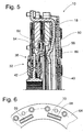
- FIGS. 5 and 6 show an alternative type of design, wherein here there are differences essentially in the configuration of the driver formation and the counter-driver formation. Therefore, in the following, essentially only the differences will be discussed.
- the remaining one Structure of the multi-plate clutch 10 corresponds to the above-described, so that reference can be made to this embodiment.
- driver formation 54 is realized on the cover disk element 40 again in its radially outer region by a plurality of axially bent driver projections 56. However, these are now bent away in the direction of the cover disk element 42 and thus extend in the direction of the pressure plate 18.
- FIGS. 7 and 8 show an embodiment variant in which the driver projections 56 in turn protrude axially from the cover disk element 40.
- the bend line about which the cam projections 56 are bent with respect to the body portion 72 of the cover disk member 40 does not extend approximately circumferentially or tangentially as in the previously described embodiments, but is substantially radial Direction, possibly with a peripheral inclination component extends.
- sections 82 are provided on the body region 72 radially outward, the first in the circumferential direction away extending and not further connected to the body portion 72 lobes, which are subsequently bent over the approximately radially extending bend line, so that the substantially axially extending driver projections 56 are obtained.
- driver projections 56 extending counter-Mit nowadaysaussparungen 70 are provided on the coupling element 64 of the friction lining assembly 50 with corresponding radial extent, ie, primarily from radially outside to radially inside, in which the Mit predominantlyvorsprünge 56 engage ,
- FIGS. 9 and 10 A modification to this is shown in FIGS. 9 and 10. It can be seen that the driver projections 56, which in turn are bent about an approximately radially extending bending line with respect to the body portion 72, are not provided on radially outward extensions of the body portion 72, but that by providing U-shaped punched-out portions initially in the circumferential direction extending tabs shown in phantom in Fig. 10, which are then bent to provide the approximately axially extending cam projections 56 from the plane of the body portion 72.
- FIGS. 11 and 12 show an embodiment variant in which the driver formation 54 provided on the cover disk element 40 is provided by driver projections 56, which are not extending substantially radially and are not bent relative to the body region 72.
- the counter-cam formation 66 is provided by a plurality of now axially bent counter-cam projections 68, between which the counter-cam recesses 70 which can also be seen in FIG. In this counter-engagement recesses 70 engage the radially outwardly extending driver projections 56th one.
- the driver projections 56 as shown in FIG.
- FIGS. 13 to 15 show a first such embodiment variant. It can be seen that on the cover disk element 40 or the disk-like body region 72 of the same in the radially outer region, ie radially outside the damper element arrangement 46, a plurality of driver projections 56 are defined as separate components in the circumferential direction successively. This can be done, for example, by welding on the driver projections 56 providing and approximately in the tangential and axial direction extending plate parts. In association with this, in the coupling element 64 of the friction lining assembly 50, a plurality of counter-engagement recesses 70 extending in the circumferential direction or tangential direction are again provided, in which the driving projections 56 engage axially. So here is basically one of the embodiment of FIGS. 5 and 6 created very similar arrangement, but in which the driver projections 56 do not form an integral part of the cover plate member 40, but are fixed thereto.
- the separately formed Mit psychologyvorsprünge 56 can not be fixed or not only by welding on the cover plate member 40, but that the connection can for example also be realized as the connection of the Mitprogressivelyvorsprünge 56 with the cover plate member 42 of FIG. 1 illustrated embodiment.
- FIGS. 16 and 17 Another alternative embodiment is shown in FIGS. 16 and 17.
- the driver formation 54 is not an integral part of one of the cover disk elements 40 or 42.
- a ring-like driver element 84 is provided, which is connected in the radially outer region with the cover disk elements 40, 42.
- the annular entrainment element 84 has at one axial end region projections 86 which pass through openings 88 in the cover disk element 42 and are shaped such that a form-fitting holding effect is achieved.
- the carrier arrangement 58 of the friction lining assembly 52 is fixed radially within this fixed connection between the cover disk element 42 and the driver element 84 on the cover disk element 42.
- the driver element 84 has the driver formation 54 in the form of a plurality of substantially axially extending driver projections 56. Between these driver projections 56 engage radially outwardly extending coupling projections 90 of the cover plate member 40, and that substantially without movement, so that, if necessary, even here an interference fit can be realized. In this way, a fixed support of the cover plate member 40 may be realized on the driver element 84.
- the driver projections 56 extend axially beyond the cover disk element 40 for coupling with the counter-driver formation 66 on the coupling element 64 of the friction lining assembly 50. It can be seen in FIG.
- this annular coupling element 64 is now arranged so as to be substantially lies radially within the annular carrier element 84 and the counter cam follower 66 extends with its counter-driver projections 68 substantially radially outward.
- both carrier assemblies 58, 62 may be configured substantially equal to each other, so that in the realization of the same as pad suspension also results in a substantially identical pad suspension behavior.
Landscapes
- Engineering & Computer Science (AREA)
- General Engineering & Computer Science (AREA)
- Mechanical Engineering (AREA)
- Mechanical Operated Clutches (AREA)
- Hydraulic Clutches, Magnetic Clutches, Fluid Clutches, And Fluid Joints (AREA)
Applications Claiming Priority (1)
| Application Number | Priority Date | Filing Date | Title |
|---|---|---|---|
| DE102005021344 | 2005-05-04 |
Publications (3)
| Publication Number | Publication Date |
|---|---|
| EP1719930A2 true EP1719930A2 (fr) | 2006-11-08 |
| EP1719930A3 EP1719930A3 (fr) | 2007-05-30 |
| EP1719930B1 EP1719930B1 (fr) | 2010-01-27 |
Family
ID=36649737
Family Applications (1)
| Application Number | Title | Priority Date | Filing Date |
|---|---|---|---|
| EP06008476A Not-in-force EP1719930B1 (fr) | 2005-05-04 | 2006-04-25 | Ensemble de disque d'embrayage pour embrayages multiples, en particulier embrayage à deux disques |
Country Status (4)
| Country | Link |
|---|---|
| US (1) | US7650975B2 (fr) |
| EP (1) | EP1719930B1 (fr) |
| AT (1) | ATE456750T1 (fr) |
| DE (1) | DE502006006020D1 (fr) |
Cited By (2)
| Publication number | Priority date | Publication date | Assignee | Title |
|---|---|---|---|---|
| EP1729024A3 (fr) * | 2005-06-04 | 2009-04-15 | Zf Friedrichshafen Ag | Disposition d'un moyeu et disque d'embrayage pour un embrayage à friction, en particulier embrayage à disques multiple |
| WO2013088211A1 (fr) * | 2011-12-14 | 2013-06-20 | Eaton Corporation | Amortisseur en série pour embrayage de grande puissance à double plateau de friction |
Families Citing this family (1)
| Publication number | Priority date | Publication date | Assignee | Title |
|---|---|---|---|---|
| US8430222B2 (en) * | 2009-11-02 | 2013-04-30 | Tnmj Caliber, Llc | Friction clutch system |
Family Cites Families (4)
| Publication number | Priority date | Publication date | Assignee | Title |
|---|---|---|---|---|
| FR2411999A2 (fr) * | 1977-02-25 | 1979-07-13 | Ferodo Sa | Friction d'embrayage a moyeu amortisseur pour vehicule automobile |
| US5501310A (en) * | 1993-08-20 | 1996-03-26 | Kabushiki Kaisha Daikin Seisakusho | Motorcycle clutch device |
| JP3518959B2 (ja) * | 1996-09-25 | 2004-04-12 | 株式会社エクセディ | ツインクラッチ |
| GB0009514D0 (en) * | 1999-05-19 | 2000-06-07 | Mannesmann Sachs Ag | Clutch disc arrangement for a multiple disc clutch |
-
2006
- 2006-04-25 AT AT06008476T patent/ATE456750T1/de active
- 2006-04-25 DE DE502006006020T patent/DE502006006020D1/de active Active
- 2006-04-25 EP EP06008476A patent/EP1719930B1/fr not_active Not-in-force
- 2006-05-03 US US11/416,746 patent/US7650975B2/en not_active Expired - Fee Related
Non-Patent Citations (1)
| Title |
|---|
| None |
Cited By (2)
| Publication number | Priority date | Publication date | Assignee | Title |
|---|---|---|---|---|
| EP1729024A3 (fr) * | 2005-06-04 | 2009-04-15 | Zf Friedrichshafen Ag | Disposition d'un moyeu et disque d'embrayage pour un embrayage à friction, en particulier embrayage à disques multiple |
| WO2013088211A1 (fr) * | 2011-12-14 | 2013-06-20 | Eaton Corporation | Amortisseur en série pour embrayage de grande puissance à double plateau de friction |
Also Published As
| Publication number | Publication date |
|---|---|
| US20060249347A1 (en) | 2006-11-09 |
| EP1719930A3 (fr) | 2007-05-30 |
| ATE456750T1 (de) | 2010-02-15 |
| EP1719930B1 (fr) | 2010-01-27 |
| US7650975B2 (en) | 2010-01-26 |
| DE502006006020D1 (de) | 2010-03-18 |
Similar Documents
| Publication | Publication Date | Title |
|---|---|---|
| EP2387674B1 (fr) | Système à embrayages multiples | |
| EP1693588B1 (fr) | Arrangement pour le support axial de deux éléments rotatifs. | |
| EP1862689B2 (fr) | Agencement de transmission d'un couple de rotation pour le conducteur de commande d'un véhicule | |
| DE19802251B4 (de) | Schlingfederkupplung | |
| WO2012110018A1 (fr) | Dispositif de transmission de couple de rotation | |
| WO2017186209A1 (fr) | Embrayage à répartition du flux de couple en vue d'un renforcement partiel | |
| WO2021228303A1 (fr) | Ensemble d'embrayage multidisques ayant des unités de plaque de ressort à action indépendante pour relier deux disques de composant à un arbre de sortie | |
| EP2340378A1 (fr) | Agencement amortisseur de vibrations torsionnelles, en particulier pour la chaîne cinématique d'un véhicule | |
| DE10156041B4 (de) | Hydrodynamische Kopplungseinrichtung | |
| WO2015120845A1 (fr) | Dispositif d'embrayage normalement embrayé | |
| EP2347145B1 (fr) | Amortisseur de vibrations torsionnelles pour la chaîne cinématique d'un véhicule | |
| DE10024088A1 (de) | Kupplungsscheibenanordnung für eine Mehrscheibenkupplung | |
| DE102011100864A1 (de) | Reibungskupplungseinrichtung | |
| EP3728889B1 (fr) | Unité de transmission de couple et chaîne cinématique | |
| EP1719930B1 (fr) | Ensemble de disque d'embrayage pour embrayages multiples, en particulier embrayage à deux disques | |
| EP1862685A1 (fr) | Agencement de transmission d'un couple de rotation pour le conducteur de commande d'un véhicule | |
| EP1647729A2 (fr) | Dispositif d'embrayages pour embrayages multiples | |
| EP1653103A2 (fr) | Dispositif d'embrayages pour embrayages multiples | |
| DE102005049669A1 (de) | Kupplungsscheibenanordnung für eine Mehrscheibenkupplung | |
| EP3953595B1 (fr) | Embrayage multidisque, en particulier embrayage multidisque sec, en particulier pour une chaîne cinématique hybride | |
| DE102006015907A1 (de) | Kupplungsscheibenanordnung für eine Mehrscheibenkupplung, insbesondere Zweischeibenkupplung | |
| EP1387104B1 (fr) | Moyens d'équilibrage dans un embrayage à friction | |
| EP1712807A1 (fr) | Système de transmission de couple | |
| EP3874174B1 (fr) | Embrayage à friction | |
| EP1950452A1 (fr) | Agencement d'amortissement des oscillations de torsion pour une transmission de véhicule |
Legal Events
| Date | Code | Title | Description |
|---|---|---|---|
| PUAI | Public reference made under article 153(3) epc to a published international application that has entered the european phase |
Free format text: ORIGINAL CODE: 0009012 |
|
| AK | Designated contracting states |
Kind code of ref document: A2 Designated state(s): AT BE BG CH CY CZ DE DK EE ES FI FR GB GR HU IE IS IT LI LT LU LV MC NL PL PT RO SE SI SK TR |
|
| AX | Request for extension of the european patent |
Extension state: AL BA HR MK YU |
|
| PUAL | Search report despatched |
Free format text: ORIGINAL CODE: 0009013 |
|
| AK | Designated contracting states |
Kind code of ref document: A3 Designated state(s): AT BE BG CH CY CZ DE DK EE ES FI FR GB GR HU IE IS IT LI LT LU LV MC NL PL PT RO SE SI SK TR |
|
| AX | Request for extension of the european patent |
Extension state: AL BA HR MK YU |
|
| 17P | Request for examination filed |
Effective date: 20070518 |
|
| 17Q | First examination report despatched |
Effective date: 20070905 |
|
| AKX | Designation fees paid |
Designated state(s): AT BE BG CH CY CZ DE DK EE ES FI FR GB GR HU IE IS IT LI LT LU LV MC NL PL PT RO SE SI SK TR |
|
| GRAP | Despatch of communication of intention to grant a patent |
Free format text: ORIGINAL CODE: EPIDOSNIGR1 |
|
| GRAS | Grant fee paid |
Free format text: ORIGINAL CODE: EPIDOSNIGR3 |
|
| GRAA | (expected) grant |
Free format text: ORIGINAL CODE: 0009210 |
|
| AK | Designated contracting states |
Kind code of ref document: B1 Designated state(s): AT BE BG CH CY CZ DE DK EE ES FI FR GB GR HU IE IS IT LI LT LU LV MC NL PL PT RO SE SI SK TR |
|
| REG | Reference to a national code |
Ref country code: GB Ref legal event code: FG4D Free format text: NOT ENGLISH |
|
| REG | Reference to a national code |
Ref country code: CH Ref legal event code: EP |
|
| REG | Reference to a national code |
Ref country code: IE Ref legal event code: FG4D |
|
| REF | Corresponds to: |
Ref document number: 502006006020 Country of ref document: DE Date of ref document: 20100318 Kind code of ref document: P |
|
| REG | Reference to a national code |
Ref country code: NL Ref legal event code: VDEP Effective date: 20100127 |
|
| LTIE | Lt: invalidation of european patent or patent extension |
Effective date: 20100127 |
|
| PG25 | Lapsed in a contracting state [announced via postgrant information from national office to epo] |
Ref country code: PT Free format text: LAPSE BECAUSE OF FAILURE TO SUBMIT A TRANSLATION OF THE DESCRIPTION OR TO PAY THE FEE WITHIN THE PRESCRIBED TIME-LIMIT Effective date: 20100527 Ref country code: IS Free format text: LAPSE BECAUSE OF FAILURE TO SUBMIT A TRANSLATION OF THE DESCRIPTION OR TO PAY THE FEE WITHIN THE PRESCRIBED TIME-LIMIT Effective date: 20100527 Ref country code: LT Free format text: LAPSE BECAUSE OF FAILURE TO SUBMIT A TRANSLATION OF THE DESCRIPTION OR TO PAY THE FEE WITHIN THE PRESCRIBED TIME-LIMIT Effective date: 20100127 Ref country code: ES Free format text: LAPSE BECAUSE OF FAILURE TO SUBMIT A TRANSLATION OF THE DESCRIPTION OR TO PAY THE FEE WITHIN THE PRESCRIBED TIME-LIMIT Effective date: 20100508 Ref country code: NL Free format text: LAPSE BECAUSE OF FAILURE TO SUBMIT A TRANSLATION OF THE DESCRIPTION OR TO PAY THE FEE WITHIN THE PRESCRIBED TIME-LIMIT Effective date: 20100127 |
|
| REG | Reference to a national code |
Ref country code: IE Ref legal event code: FD4D |
|
| REG | Reference to a national code |
Ref country code: HU Ref legal event code: AG4A Ref document number: E007925 Country of ref document: HU |
|
| PG25 | Lapsed in a contracting state [announced via postgrant information from national office to epo] |
Ref country code: SI Free format text: LAPSE BECAUSE OF FAILURE TO SUBMIT A TRANSLATION OF THE DESCRIPTION OR TO PAY THE FEE WITHIN THE PRESCRIBED TIME-LIMIT Effective date: 20100127 Ref country code: FI Free format text: LAPSE BECAUSE OF FAILURE TO SUBMIT A TRANSLATION OF THE DESCRIPTION OR TO PAY THE FEE WITHIN THE PRESCRIBED TIME-LIMIT Effective date: 20100127 Ref country code: LV Free format text: LAPSE BECAUSE OF FAILURE TO SUBMIT A TRANSLATION OF THE DESCRIPTION OR TO PAY THE FEE WITHIN THE PRESCRIBED TIME-LIMIT Effective date: 20100127 Ref country code: PL Free format text: LAPSE BECAUSE OF FAILURE TO SUBMIT A TRANSLATION OF THE DESCRIPTION OR TO PAY THE FEE WITHIN THE PRESCRIBED TIME-LIMIT Effective date: 20100127 |
|
| PG25 | Lapsed in a contracting state [announced via postgrant information from national office to epo] |
Ref country code: GR Free format text: LAPSE BECAUSE OF FAILURE TO SUBMIT A TRANSLATION OF THE DESCRIPTION OR TO PAY THE FEE WITHIN THE PRESCRIBED TIME-LIMIT Effective date: 20100428 Ref country code: EE Free format text: LAPSE BECAUSE OF FAILURE TO SUBMIT A TRANSLATION OF THE DESCRIPTION OR TO PAY THE FEE WITHIN THE PRESCRIBED TIME-LIMIT Effective date: 20100127 Ref country code: IE Free format text: LAPSE BECAUSE OF FAILURE TO SUBMIT A TRANSLATION OF THE DESCRIPTION OR TO PAY THE FEE WITHIN THE PRESCRIBED TIME-LIMIT Effective date: 20100127 Ref country code: SE Free format text: LAPSE BECAUSE OF FAILURE TO SUBMIT A TRANSLATION OF THE DESCRIPTION OR TO PAY THE FEE WITHIN THE PRESCRIBED TIME-LIMIT Effective date: 20100127 Ref country code: RO Free format text: LAPSE BECAUSE OF FAILURE TO SUBMIT A TRANSLATION OF THE DESCRIPTION OR TO PAY THE FEE WITHIN THE PRESCRIBED TIME-LIMIT Effective date: 20100127 Ref country code: CY Free format text: LAPSE BECAUSE OF FAILURE TO SUBMIT A TRANSLATION OF THE DESCRIPTION OR TO PAY THE FEE WITHIN THE PRESCRIBED TIME-LIMIT Effective date: 20100127 |
|
| BERE | Be: lapsed |
Owner name: ZF FRIEDRICHSHAFEN A.G. Effective date: 20100430 |
|
| PG25 | Lapsed in a contracting state [announced via postgrant information from national office to epo] |
Ref country code: MC Free format text: LAPSE BECAUSE OF NON-PAYMENT OF DUE FEES Effective date: 20100430 Ref country code: SK Free format text: LAPSE BECAUSE OF FAILURE TO SUBMIT A TRANSLATION OF THE DESCRIPTION OR TO PAY THE FEE WITHIN THE PRESCRIBED TIME-LIMIT Effective date: 20100127 Ref country code: CZ Free format text: LAPSE BECAUSE OF FAILURE TO SUBMIT A TRANSLATION OF THE DESCRIPTION OR TO PAY THE FEE WITHIN THE PRESCRIBED TIME-LIMIT Effective date: 20100127 Ref country code: BG Free format text: LAPSE BECAUSE OF FAILURE TO SUBMIT A TRANSLATION OF THE DESCRIPTION OR TO PAY THE FEE WITHIN THE PRESCRIBED TIME-LIMIT Effective date: 20100427 |
|
| PLBE | No opposition filed within time limit |
Free format text: ORIGINAL CODE: 0009261 |
|
| STAA | Information on the status of an ep patent application or granted ep patent |
Free format text: STATUS: NO OPPOSITION FILED WITHIN TIME LIMIT |
|
| GBPC | Gb: european patent ceased through non-payment of renewal fee |
Effective date: 20100427 |
|
| 26N | No opposition filed |
Effective date: 20101028 |
|
| PG25 | Lapsed in a contracting state [announced via postgrant information from national office to epo] |
Ref country code: DK Free format text: LAPSE BECAUSE OF FAILURE TO SUBMIT A TRANSLATION OF THE DESCRIPTION OR TO PAY THE FEE WITHIN THE PRESCRIBED TIME-LIMIT Effective date: 20100127 |
|
| PG25 | Lapsed in a contracting state [announced via postgrant information from national office to epo] |
Ref country code: GB Free format text: LAPSE BECAUSE OF NON-PAYMENT OF DUE FEES Effective date: 20100427 Ref country code: IT Free format text: LAPSE BECAUSE OF FAILURE TO SUBMIT A TRANSLATION OF THE DESCRIPTION OR TO PAY THE FEE WITHIN THE PRESCRIBED TIME-LIMIT Effective date: 20100127 Ref country code: BE Free format text: LAPSE BECAUSE OF NON-PAYMENT OF DUE FEES Effective date: 20100430 |
|
| PG25 | Lapsed in a contracting state [announced via postgrant information from national office to epo] |
Ref country code: LU Free format text: LAPSE BECAUSE OF NON-PAYMENT OF DUE FEES Effective date: 20100425 |
|
| PG25 | Lapsed in a contracting state [announced via postgrant information from national office to epo] |
Ref country code: TR Free format text: LAPSE BECAUSE OF FAILURE TO SUBMIT A TRANSLATION OF THE DESCRIPTION OR TO PAY THE FEE WITHIN THE PRESCRIBED TIME-LIMIT Effective date: 20100127 |
|
| REG | Reference to a national code |
Ref country code: AT Ref legal event code: MM01 Ref document number: 456750 Country of ref document: AT Kind code of ref document: T Effective date: 20110425 |
|
| PG25 | Lapsed in a contracting state [announced via postgrant information from national office to epo] |
Ref country code: AT Free format text: LAPSE BECAUSE OF NON-PAYMENT OF DUE FEES Effective date: 20110425 |
|
| PGFP | Annual fee paid to national office [announced via postgrant information from national office to epo] |
Ref country code: CH Payment date: 20140414 Year of fee payment: 9 |
|
| REG | Reference to a national code |
Ref country code: CH Ref legal event code: PL |
|
| PG25 | Lapsed in a contracting state [announced via postgrant information from national office to epo] |
Ref country code: CH Free format text: LAPSE BECAUSE OF NON-PAYMENT OF DUE FEES Effective date: 20150430 Ref country code: LI Free format text: LAPSE BECAUSE OF NON-PAYMENT OF DUE FEES Effective date: 20150430 |
|
| REG | Reference to a national code |
Ref country code: FR Ref legal event code: PLFP Year of fee payment: 11 |
|
| REG | Reference to a national code |
Ref country code: FR Ref legal event code: PLFP Year of fee payment: 12 |
|
| REG | Reference to a national code |
Ref country code: FR Ref legal event code: PLFP Year of fee payment: 13 |
|
| PGFP | Annual fee paid to national office [announced via postgrant information from national office to epo] |
Ref country code: FR Payment date: 20220308 Year of fee payment: 17 |
|
| PGFP | Annual fee paid to national office [announced via postgrant information from national office to epo] |
Ref country code: HU Payment date: 20220319 Year of fee payment: 17 Ref country code: DE Payment date: 20220302 Year of fee payment: 17 |
|
| REG | Reference to a national code |
Ref country code: DE Ref legal event code: R119 Ref document number: 502006006020 Country of ref document: DE |
|
| PG25 | Lapsed in a contracting state [announced via postgrant information from national office to epo] |
Ref country code: HU Free format text: LAPSE BECAUSE OF NON-PAYMENT OF DUE FEES Effective date: 20230426 Ref country code: FR Free format text: LAPSE BECAUSE OF NON-PAYMENT OF DUE FEES Effective date: 20230430 Ref country code: DE Free format text: LAPSE BECAUSE OF NON-PAYMENT OF DUE FEES Effective date: 20231103 |