EP1719660A2 - Hinge arrangement for a tailboard - Google Patents
Hinge arrangement for a tailboard Download PDFInfo
- Publication number
- EP1719660A2 EP1719660A2 EP06007786A EP06007786A EP1719660A2 EP 1719660 A2 EP1719660 A2 EP 1719660A2 EP 06007786 A EP06007786 A EP 06007786A EP 06007786 A EP06007786 A EP 06007786A EP 1719660 A2 EP1719660 A2 EP 1719660A2
- Authority
- EP
- European Patent Office
- Prior art keywords
- arrangement according
- bearing
- container
- axis
- rotation
- Prior art date
- Legal status (The legal status is an assumption and is not a legal conclusion. Google has not performed a legal analysis and makes no representation as to the accuracy of the status listed.)
- Granted
Links
Images


Classifications
-
- B—PERFORMING OPERATIONS; TRANSPORTING
- B60—VEHICLES IN GENERAL
- B60P—VEHICLES ADAPTED FOR LOAD TRANSPORTATION OR TO TRANSPORT, TO CARRY, OR TO COMPRISE SPECIAL LOADS OR OBJECTS
- B60P1/00—Vehicles predominantly for transporting loads and modified to facilitate loading, consolidating the load, or unloading
- B60P1/04—Vehicles predominantly for transporting loads and modified to facilitate loading, consolidating the load, or unloading with a tipping movement of load-transporting element
- B60P1/26—Means for controlling movement of tailboards or sideboards
Definitions
- the invention relates to a vehicle container assembly having a pivotable container wall and a hinge assembly between a container frame and a container wall.
- Such vehicle container arrangements with a container wall pivotable about a horizontal pivot axis are, in particular, tiltable containers with a tailgate hingedly suspended in a hinge arrangement on a container frame.
- tiltable containers with a tailgate hingedly suspended in a hinge arrangement on a container frame.
- the smallest possible gap between the container wall and the container opening closed by the latter is essential.
- the hinge assembly frame side On a support body which is fixed to the frame, wherein the position of the support body and thus given by this position of the pivot axis relative to the container frame in a small Scope is adjustable.
- the support body parallel to the pivot axis on a horizontal and a vertical surface, which faces surfaces of the container frame.
- the distances of the opposing surfaces can be varied and an optimal position for the pivot axis can be adjusted.
- spacer plates are inserted between opposing surfaces.
- the invention has for its object to provide an advantageous vehicle container assembly with a pivotable container wall and a hinge assembly between a container frame and a container wall, in particular a vehicle container assembly with improved possibility for setting an optimal position of the pivot axis.
- a rotatable about a first axis of rotation first actuator with an eccentric to the first axis of rotation bearing surface over which the support body is supported with a counter-bearing surface against the container frame allows a particularly simple and advantageous manner, a change in the position of the support body relative to the holding frame.
- the axis of rotation eccentric course is a priori not concentric with the rotation axis course understood with woowinkelukem distance of the contact surface of the rotation axis, whereby upon rotation of the actuator, a preferably continuous change in position of the support body relative to the container frame can be achieved.
- the abutment surface extends in a circle around an offset from the axis of rotation center.
- Under the attachment to the container frame is generally a fixture fixed relative to the container regarded as rigid considered, with fixed elements connected to parts of the container frame can serve as a mounting base.
- the first axis of rotation and / or the second axis of rotation is aligned parallel to the pivot axis.
- the change in position of the carrier body relative to the carrier body upon actuation of the adjusting means by rotating the first and the second actuator about the respective axis of rotation is advantageously perpendicular to the pivot axis with parallel displacement of the pivot axis.
- the carrier body is advantageously guided on the frame along a plane extending transversely, preferably perpendicular to the pivot axis.
- the carrier body is designed as a metallic plate, which is preferably carried out in the region of the system to the contact surface of the first and / or optionally the second actuator substantially planar.
- the rotatable about the respective axis of rotation actuators are advantageously fixed in different, preferably continuously adjustable rotational positions.
- the actuators By fixing the actuators in a set rotational position, the support of the carrier body is maintained via the actuators.
- additional means for fixing the carrier body are provided.
- the axes of rotation of the two actuators are advantageously arranged angularly offset with respect to the pivot axis by an angle of approximately 90 °, in particular between 70 ° and 110 °.
- the at least one first actuator preferably also the second actuator, is advantageously rotatably mounted in the container frame and fixed in various representations on the container frame, in particular screwed, wherein the screw axis preferably coincides with the axis of rotation.
- the actuators have for rotation advantageously a non-rotationally symmetric structure, for example a polygonal structure, as a tool approach.
- a non-rotationally symmetric structure for example a polygonal structure
- an operation of the adjusting devices in hinged and in the closed position befindaji container wall is possible, as well as a determination of the actuators or a release of such a definition for readjustment.
- a bearing pin is connected as a frame-side part of the pivot joint arrangement with the support body, which forms a pivot bearing with a recess in a pivot arm on the side of the container wall.
- the bearing pin can extend in a particularly advantageous embodiment through the carrier body through to the container frame and serve to fix the carrier body on the container frame parallel and transverse to the pivot axis.
- the bearing pin can have a screw thread, in particular on the side facing the container frame.
- the wall-side portion of the pivot joint assembly is advantageously formed as a plate-shaped extension from a side edge of the container wall, wherein the pivot axis is spaced horizontally and / or vertically against the upper edge of the container wall of the container wall.
- a hinge assembly for swinging suspension of a container wall, in which a bearing spigot is clamped on one side of the container frame and deviating from conventional container wall-mounted bearings with container-side storage forks, the storage container side and wall side only einschalig (single-ended) is formed.
- the bearing pin protrudes in a preferred embodiment with a free end, which is advantageously completed by a bolt head, in particular with tool attachment, beyond the support body and the bearing surface of the pivot joint assembly is arranged in the axial direction in the region of the support body to the bolt head projecting end.
- the bearing surface can be formed in a particularly advantageous embodiment by the bolt shank in the free end of the bolt itself.
- the bolt shank runs advantageously radially stepped in the axial direction in such a way that the diameter in the axial region between the carrier body and bolt head is greater than in the engaging in the recess in the carrier body part of the bolt shaft and the bolt with the step or collar at the edge the recess of the carrier body is supported on this and is clamped axially against it.
- a bearing sleeve can be plugged onto the bolt and form the bearing surface.
- the bearing pin is formed in a preferred embodiment as a so-called stepped bolt or collar bolts, which is axially supported on the support body with the step or the collar.
- the axial length of the bearing surface is advantageously greater than the thickness of the container wall-side part of the pivot bearing forming pivot arm, so that one side or both sides of the pivot arm remains a narrow gap to the bolt head and / or to the carrier body out, creating a particularly low-friction storage of the container wall in the Swivel joint arrangement is achieved and the bolt held in a stable position on the carrier body is.
- the excess of the axial length of the bearing surface against the axial thickness of the pivot arm in the axial direction is advantageously at least 4%, in particular at least 7.5% or at most 20%, in particular at most 15% of the axial length of the bearing surface.
- the execution of the pivot joint arrangement with the einschaligen on the frame side and container wall side bearing with a collar bolt is also independent of the adjustability of the pivot axis position by means of an adjustable support body of particular advantage and can be particularly advantageous for fixed pivot axis and without interposition of a support body with attachment of the collar bolt directly to the container frame be feasible.
- Such a bearing design is on the one hand the high stability requirement for the pendulum mounting of the heavy tailgate just and at the same time provides easy mounting and dismounting of the tailgate on the frame with a low axial depth in the axial direction.
- the one-sided bearing with the collar bolt is simpler and thus more cost-effective and more reliable in the surface treatment for corrosion protection and / or paint on all sides accessible.
- the contact surface of the at least one first actuator is advantageously designed as a peripheral surface along the edge of a disc.
- the disc is in a preferred embodiment, an eccentric to the axis of rotation of the actuator disc.
- the disc is located in a recess of the carrier body.
- the recess may have an oval shape according to an advantageous embodiment.
- An inner wall surface of the recess forms the counter bearing surface to the contact surface of the actuator.
- the axial tension of the bolt against the carrier body is preferably used at the same time for clamping the carrier body against the container frame.
- By both the carrier body and a plate of the container frame by cross-bolt length results in a high support against tilting of the bolt.
- the embodiment of the pivot bearing arrangement with the bearing surface at a free end of a bearing pin and the tension of the bearing pin against the container frame via a step or a collar of the bearing pin are measures which are also independent of the execution of the adjustment of particular advantage.
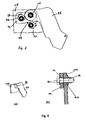
- Fig. 1 a section of a vehicle container assembly according to the invention is shown in an oblique view, which represents details of a pivot joint assembly. Further details can also be seen in particular from the sectional illustrations according to FIG. 5 and FIG. 6.
- the vehicle container may, in particular, be an upwardly open dump body which has a tailgate suspended at its upper edge at the rear.
- the tailgate closes in the lowered state of the dump body, the rear failure opening of the dump body.
- the tailgate may be lockable in the closed position.
- the dump body can be tilted in the usual manner by a tilting axis arranged at the bottom of the dump body by lifting the front area in order to dispense bulk goods transported in the dump body via the rear opening.
- the unlocked tailgate is due to the pendulum suspension in a pivot bearing at the top of the tailgate, the opening when lifting the front of the dump body free, so that the bulk material can fall backwards.
- Fig. 1 From the tailgate of such a dump body suspended as a hinged container wall is shown in Fig. 1 only one of the flat tailgate to the pivot joint arrangement continuing pendulum PA partial.
- the pendulum PA is as firm with the only with a broken line indicated tailgate HK connected, in particular considered welded.
- a support body LT is inserted, which carries the frame-side part of a self-aligning bearing, in the example sketched in the form of a bearing pin BL with a circular cylindrical bearing surface PL.
- the trained on the part of the pendulum arm PA part of the pendulum bearing is preferably given by a relative to the pendulum arm PA stationary circular, a circular cylindrical bearing surface of the bearing bolt surrounding bearing recess in the pendulum.
- Fig. 1 Shown in Fig. 1 is an x-y-z coordinate system, wherein the y-direction parallel to the pivot axis SA of the pendulum bearing, the x-axis perpendicular to this pivot axis horizontally and the z-axis perpendicular to the pivot axis vertically.
- the bearing pin BL is transverse to the pivot axis, d. H. in an x-z plane, relative to the bearing plate LP considered to be stationary, held adjustably thereon.
- the bearing pin is at the end facing away from the carrier body of the bearing surface by the bolt head, which in turn has a larger diameter than the bearing surface, completed.
- a tool approach such as an external hexagon shape educated.
- the axial length of the bearing surface is slightly larger than the axial thickness of the pendulum arm PA, so that the pendulum arm is mounted with low friction on the bearing surface with axial play.
- the axial gap SP is advantageously between 4% and 20% of the thickness of the pendulum arm.
- the bearing pin is z. B. via a screwed onto a bolt thread nut BM with the stage between bolt shank BS and bearing surface against the support body firmly clamped and thereby kept stable in position.
- the support body LT preferably consists of a flat metallic plate and lies flat against a flat surface of the bearing plate LP.
- a first recess AH and a second recess AV are given, which are spaced from the recess AB for receiving the bearing pin BL.
- a first recess AH in the carrier body LT is preferably arranged predominantly horizontally, a second recess AV is arranged predominantly vertically spaced from the recess AB for the bearing bolt BL.
- the hinge assembly is advantageously both on the frame side with the plate-shaped support body LT as well as on the side of the container wall with the pendulum PA each with a single shell, in particular designed as a plate or plate section. This results in an advantageously simple design with low axial depth.
- the actuators include circular discs which are rotatable about axes of rotation DH and DV of bolts BH and BV and in any rotational position by tightening the bolts against the bearing plate LP can be clamped and thereby fixed in the respective rotational position.
- the circular disks are arranged eccentrically to the axes of rotation DH and DV. For rotating the circular disks, these advantageously have one not rotationally symmetrical tool approach.
- a nut is firmly connected to the circular discs, in particular welded, which advantageously as a tool approach for rotating the discs around the bolt in any rotational positions and at the same time fixing the discs in selected rotational positions by tightening the bolts BH or BV serves.
- the determination of the support body LT relative to the support plate LP can also be done by other fasteners or by modifying the actuators.
- the determination about the bearing pin is particularly advantageous because of the small number of components. In the fixed state of the support body LT this is held perpendicular to the support plate LP primarily by the braced bearing pin BL and supported transversely to the pivot axis SA by the force-locking on the bearing plate LP in certain rotational position specified actuators SH and SV against the bearing plate.
- the recesses AH and AV in the carrier body are each executed in the preferred embodiment outlined oval, so that the circular discs of the actuators SH and SV are guided along the large oval axis slidably and by dimensioning the short oval axis with little play in the oval recesses ,
- the long oval axis of the recess AH is oriented substantially vertically in a middle position of the carrier body LT sketched in FIG. 4, the long oval axis of the recess AV being substantially horizontal.
- the support body LT and thus also the associated in this position in a defined bearing pin is advantageously positively supported in each adjustment position relative to the bearing plate LP in the adjustment plane by the eccentric discs of the spring.
- the actuator SH guided in the recess AH is predominantly horizontally spaced from the bearing bolt BL
- the actuator SV guided in the recess AV is substantially vertically spaced from the bearing bolt BL.
- This advantageously causes a rotation of the actuator SH about the rotation axis DH substantially horizontal displacement of the position of the pivot axis SA, a rotation of the actuator SV about the rotation axis DV, however, a substantially vertical displacement of the position of the pivot axis SA.
- This favors a simple for the user intuitive and thus fast adjustment of the optimal position of the swivel axis.
- the carrier body LT is shown in a relative to the horizontal and vertical adjustment of the pivot axis position in a middle position, in which the two actuators SH and SV are each in a middle rotational position.
- the outlined rotational positions are equivalent to each rotated by 180 ° positions of the two actuators.
- the eccentric distances of the centers of the circular disks of the actuators SH and SV of the respective axes of rotation DH and DV are denoted by EH and EV.
- EH and EV are typically in a range of 2 mm to 10 mm.
- another guide member is provided in the form of a guide pin BF fixed with respect to the bearing plate LP, which is guided in a longitudinal hole AF as a further recess of the support body.
- This additional linear guide is assigned to each of a combination of positions of the two actuators SH, SV a unique position of the pivot axis.
- the position of the pivot axis in this central position of the actuators is designated by the coordinates XO and ZO.
- a flat tailgate HK is indicated as a container wall with a broken line.
- the pivot axis SA is advantageously arranged horizontally and / or vertically away from the tailgate from the top edge OK of the container wall.
- the swivel arm is advantageously plate-shaped, in particular made from a flat plate blank produced.
- the pivot axis SA is advantageously spaced over the pendulum PA from the wall surface of the tailgate HK, which is indicated by a broken line, in the horizontal and / or vertical direction.
- Fig. 3 is a relation to FIG. 2 changed position of the support body LT and thus the pivot axis SA is shown.
- the actuator SH is rotated counterclockwise by 90 ° with respect to FIG. 2, whereby substantially the horizontal displacement DX of the pivot axis SA to the left from the central position of FIG. 2 is effected.
- the likewise made rotation of the actuator SV by 90 ° clockwise in the outlined in Fig. 3 rotational position causes substantially the vertical displacement Z of the pivot axis position relative to the central position of FIG. 2 down.
- the influence of the vertical position of the pivot axis by a rotation of the actuator SH and the influence of the horizontal position of the pivot axis upon rotation of the actuator SH are negligible, so that DX is approximately equal to EH and DZ approximately equal to EV.
- a position of the support body LT is outlined in which by rotating the actuator SH by 90 ° clockwise relative to the center position of FIG. 2, the position of the pivot axis is shifted horizontally by DX to the right.
- a displacement of the position of the pivot axis in the vertical direction by DZ causes upward.
- the horizontal displacements DX according to FIG. 3 or FIG. 4 and the vertical displacements DZ essentially represent the maximum possible displacement paths in the x-direction or z-direction. All possible intermediate positions for the position of the pivot axis SA are substantially within a rectangle with side lengths 2DX and 2DZ around the center position of FIG. 2.
- one of the two recesses AH or AV can also be selected circular in adaptation to the circular disk SH or SV.
- the linear guide eliminates the guide pin BF in a recess AF. If necessary, can be provided in its place a tension of the support body LT against the bearing plate without linear guide properties.
- FIG. 7 an embodiment is sketched with a plate-shaped carrier body TS, in which the oval recess AH is replaced after the previous sketches by one of the circular disc of the actuator diameter-adapted circular recess KH is replaced and instead of the oval recess AV of the previous sketches only a lower edge UK of the support body TS is present as a counter-bearing surface to the peripheral surface of the rotary actuator SV.
- pendulum bearing a plate-shaped support body from the contact surface of the actuator SV upwardly lifting force does not occur during a Justierphase, so that the removal of the lower guide surface is unproblematic.
- the carrier body LT or TS is advantageously formed by a flat metallic plate and can thereby conveniently be used in identical form on both arranged in the longitudinal direction of the container wall at opposite ends hinge assemblies. The same applies to the bearing plate LP in a flat design.
- Fig. 8 shows in an oblique view (a) and as a sectional view (b) (corresponding to Fig. 1 and Fig. 5 for the adjustable spherical bearing) an advantageous hinge assembly with fixed, non-adjustable pivot axis, again giving the particularly advantageous structure is on the frame side with a bearing plate LPS, here without additional adjustable support body, and on the side of the container wall with the pendulum PA each has a single-shell (single-ended) bearing design.
- the bearing pin is again designed as a collar bolt, which is axially supported with a shoulder against a recess in the bearing plate.
- the one-sided bearing with the tensioned by screwing against the bearing plate collar bolt is simple and inexpensive with a few standard components compared to conventional two-section bearings or bearings with special bearing bodies or closure bodies.
- the bearing is easy to assemble and disassemble and ensures that all surface areas are reliably detected during surface treatment for corrosion protection and / or painting.
- the bearing has the high stability required for the swinging mounting of the heavy tailgate.
- the actuators can be arranged transversely to the pivot axis SA in a fixed position on the support body LT and be supported with their contact surfaces against counter-bearing surfaces of the bearing plate and the container frame and thereby cause a rotation of the support body upon rotation about the axes of rotation.
- the actuators can simultaneously serve to fix the carrier body in the direction of the pivot axis on the bearing plate.
Abstract
Description
Die Erfindung betrifft eine Fahrzeugbehälteranordnung mit einer schwenkbaren Behälterwand und eine Gelenkanordnung zwischen einem Behälterrahmen und einer Behälterwand.The invention relates to a vehicle container assembly having a pivotable container wall and a hinge assembly between a container frame and a container wall.
Derartige Fahrzeugbehälteranordnungen mit um eine horizontale Schwenkachse schwenkbarer Behälterwand sind insbesondere kippbare Behälter mit pendelnd in einer Gelenkanordnung an einem Behälterrahmen eingehängter Heckklappe. Um beim Transport von feuchtem oder feinkörnigem Schüttgut ein Austreten von Schüttgut zu vermeiden, ist ein möglichst geringer Spalt zwischen der Behälterwand und der durch diese verschlossenen Behälteröffnung wesentlich. Zugleich soll aber auch gewährleistet sein, dass die Behälterwand beim Kippvorgang des Behälters zuverlässig pendelnd öffnet.Such vehicle container arrangements with a container wall pivotable about a horizontal pivot axis are, in particular, tiltable containers with a tailgate hingedly suspended in a hinge arrangement on a container frame. In order to avoid the escape of bulk material during the transport of moist or fine-grained bulk material, the smallest possible gap between the container wall and the container opening closed by the latter is essential. At the same time, however, it should also be ensured that the container wall reliably opens during the tilting operation of the container.
Für die hierfür genaue Ausrichtung der Behälterwand bezüglich der Behälteröffnung ist es bekannt, die Gelenkanordnung rahmenseitig an einem Trägerkörper anzuordnen, welcher an dem Rahmen befestigt ist, wobei die Position des Trägerkörpers und damit auch die durch diesen gegebene Position der Schwenkachse relativ zu dem Behälterrahmen in geringem Umfang verstellbar ist. Hierzu weist in bekannter Ausführung der Trägerkörper parallel zu der Schwenkachse eine horizontale und eine vertikale Fläche auf, welchen Flächen des Behälterrahmens gegenüberstehen. Mittels Stellschrauben können die Abstände der einander gegenüberstehenden Flächen variiert und eine optimale Position für die Schwenkachse eingestellt werden. Zur Stabilisierung werden Distanzbleche zwischen gegenüberstehende Flächen eingelegt.For the purpose of this precise alignment of the container wall with respect to the container opening, it is known to arrange the hinge assembly frame side on a support body which is fixed to the frame, wherein the position of the support body and thus given by this position of the pivot axis relative to the container frame in a small Scope is adjustable. For this purpose, in a known embodiment of the support body parallel to the pivot axis on a horizontal and a vertical surface, which faces surfaces of the container frame. By means of adjusting screws, the distances of the opposing surfaces can be varied and an optimal position for the pivot axis can be adjusted. For stabilization, spacer plates are inserted between opposing surfaces.
Der Erfindung liegt die Aufgabe zugrunde, eine vorteilhafte Fahrzeugbehälteranordnung mit einer schwenkbaren Behälterwand und eine Gelenkanordnung zwischen einem Behälterrahmen und einer Behälterwand anzugeben, insbesondere eine Fahrzeugbehälteranordnung mit verbesserter Möglichkeit zur Einstellung einer optimalen Position der Schwenkachse.The invention has for its object to provide an advantageous vehicle container assembly with a pivotable container wall and a hinge assembly between a container frame and a container wall, in particular a vehicle container assembly with improved possibility for setting an optimal position of the pivot axis.
Erfindungsgemäße Lösungen sind in den unabhängigen Ansprüchen beschrieben. Die abhängigen Ansprüche enthalten vorteilhafte Ausgestaltungen und Weiterbildungen der Erfindung.Solutions according to the invention are described in the independent claims. The dependent claims contain advantageous refinements and developments of the invention.
Die Verwendung wenigstens eines um eine erste Drehachse drehbaren ersten Stellglieds mit einer zu der ersten Drehachse exzentrisch verlaufenden Anlagefläche, über welche sich der Trägerkörper mit einer Gegenanlagefläche gegen den Behälterrahmen abstützt, ermöglicht auf besonders einfache und vorteilhafte Weise eine Veränderung der Position des Trägerkörpers relativ zu dem Halterahmen. Als bezüglich der Drehachse exzentrischer Verlauf sei a priori jeder nicht zur Drehachse konzentrische Verlauf mit drehwinkelabhängigem Abstand der Anlagefläche von der Drehachse verstanden, wodurch bei Drehung des Stellglieds eine vorzugsweise kontinuierliche Positionsveränderung des Trägerkörpers relativ zum Behälterrahmen erreicht werden kann. In bevorzugter Ausführung verläuft die Anlagefläche kreisförmig um einen gegen die Drehachse versetzten Mittelpunkt.The use of at least one rotatable about a first axis of rotation first actuator with an eccentric to the first axis of rotation bearing surface over which the support body is supported with a counter-bearing surface against the container frame, allows a particularly simple and advantageous manner, a change in the position of the support body relative to the holding frame. As with respect to the axis of rotation eccentric course is a priori not concentric with the rotation axis course understood with drehwinkelabhängigem distance of the contact surface of the rotation axis, whereby upon rotation of the actuator, a preferably continuous change in position of the support body relative to the container frame can be achieved. In a preferred embodiment, the abutment surface extends in a circle around an offset from the axis of rotation center.
Unter der Befestigung am Behälterrahmen sei allgemein eine Befestigung ortsfest relativ zu dem als starr betrachteten Behälter angesehen, wobei auch fest mit Teilen des Behälterrahmens verbundene Zwischenelemente als Befestigungsbasis dienen können.Under the attachment to the container frame is generally a fixture fixed relative to the container regarded as rigid considered, with fixed elements connected to parts of the container frame can serve as a mounting base.
Vorzugsweise ist ein zweites um eine zweite Drehachse drehbares Stellglied mit einem zur zweiten Drehachse exzentrischen Verlauf einer zweiten Anlagefläche, über welche vorteilhafterweise wiederum der Trägerkörper gegen den Behälterrahmen abgestützt ist, als Teil der Justiereinrichtungen vorgesehen. Vorteilhafterweise ist die erste Drehachse und/oder die zweite Drehachse parallel zur Schwenkachse ausgerichtet.Preferably, a second rotatable about a second axis of rotation actuator with a second axis of rotation eccentric course of a second contact surface, via which advantageously in turn the carrier body is supported against the container frame, provided as part of the adjusting devices. Advantageously, the first axis of rotation and / or the second axis of rotation is aligned parallel to the pivot axis.
Die Positionsveränderung des Trägerkörpers relativ zum Trägerkörper bei Betätigung der Justiereinrichtungen durch Drehen des ersten bzw. des zweiten Stellglieds um die jeweilige Drehachse erfolgt vorteilhafterweise senkrecht zur Schwenkachse unter paralleler Verschiebung der Schwenkachse. Der Trägerkörper ist hierfür vorteilhafterweise entlang einer quer, vorzugsweise senkrecht zur Schwenkachse verlaufenden Ebene an dem Rahmen geführt.The change in position of the carrier body relative to the carrier body upon actuation of the adjusting means by rotating the first and the second actuator about the respective axis of rotation is advantageously perpendicular to the pivot axis with parallel displacement of the pivot axis. For this purpose, the carrier body is advantageously guided on the frame along a plane extending transversely, preferably perpendicular to the pivot axis.
In besonders vorteilhafter Ausführungsform ist der Trägerkörper als eine metallische Platte ausgeführt, welche vorzugsweise im Bereich der Anlage an die Anlagefläche des ersten und/oder gegebenenfalls des zweiten Stellglieds im wesentlichen eben ausgeführt ist.In a particularly advantageous embodiment, the carrier body is designed as a metallic plate, which is preferably carried out in the region of the system to the contact surface of the first and / or optionally the second actuator substantially planar.
Die um die jeweilige Drehachse verdrehbaren Stellglieder sind vorteilhafterweise in verschiedenen, vorzugsweise kontinuierlich einstellbaren Drehpositionen festlegbar. Durch die Festlegung der Stellglieder in einer eingestellten Drehposition bleibt die Abstützung des Trägerkörpers über die Stellglieder erhalten. Vorteilhafterweise sind zusätzliche Mittel zur Festlegung des Trägerkörpers vorgesehen.The rotatable about the respective axis of rotation actuators are advantageously fixed in different, preferably continuously adjustable rotational positions. By fixing the actuators in a set rotational position, the support of the carrier body is maintained via the actuators. Advantageously, additional means for fixing the carrier body are provided.
Die Drehachsen der beiden Stellglieder sind vorteilhafterweise bezüglich der Schwenkachse um einen Winkel von annähernd 90°, insbesondere zwischen 70° und 110° gegeneinander winkelversetzt angeordnet. Insbesondere ist vorteilhafterweise die Drehachse eines Stellglieds überwiegend vertikal und/oder die Drehachse des anderen Stellglieds überwiegend horizontal gegen die Schwenkachse versetzt angeordnet.The axes of rotation of the two actuators are advantageously arranged angularly offset with respect to the pivot axis by an angle of approximately 90 °, in particular between 70 ° and 110 °. In particular, it is advantageous the axis of rotation of an actuator predominantly vertically and / or arranged the axis of rotation of the other actuator predominantly horizontally offset from the pivot axis.
Das wenigstens eine erste Stellglied, vorzugsweise auch das zweite Stellglied, ist vorteilhafterweise drehbar im Behälterrahmen gelagert und in verschiedenen Darstellungen am Behälterrahmen festlegbar, insbesondere verschraubbar, wobei die Schraubenachse vorzugsweise mit der Drehachse zusammenfällt.The at least one first actuator, preferably also the second actuator, is advantageously rotatably mounted in the container frame and fixed in various representations on the container frame, in particular screwed, wherein the screw axis preferably coincides with the axis of rotation.
Die Stellglieder weisen zur Drehung vorteilhafterweise eine nicht rotationssymmetrische Struktur, beispielsweise eine Mehrkantstruktur, als Werkzeugansatz auf. Vorteilhafterweise ist eine Betätigung der Justiereinrichtungen bei eingehängter und in Schließstellung befindlicher Behälterwand möglich, ebenso eine Festlegung der Stellglieder oder ein Lösen einer solchen Festlegung zur Nachjustierung.The actuators have for rotation advantageously a non-rotationally symmetric structure, for example a polygonal structure, as a tool approach. Advantageously, an operation of the adjusting devices in hinged and in the closed position befindlicher container wall is possible, as well as a determination of the actuators or a release of such a definition for readjustment.
Vorteilhafterweise ist mit dem Trägerkörper ein Lagerbolzen als rahmenseitiger Teil der Schwenkgelenkanordnung verbunden, welcher mit einer Aussparung in einem Schwenkarm auf Seiten der Behälterwand ein Schwenklager bildet. Der Lagerbolzen kann in besonders vorteilhafter Ausführung durch den Trägerkörper hindurch bis zu dem Behälterrahmen reichen und zur Festlegung des Trägerkörpers am Behälterrahmen parallel und quer zur Schwenkachse dienen. Der Lagerbolzen kann hierfür insbesondere auf der dem Behälterrahmen zuweisenden Seite ein Schraubgewinde aufweisen. Der wandseitige Teil der Schwenkgelenkanordnung ist vorteilhafterweise als ein plattenförmiger Fortsatz von einer Seitenkante der Behälterwand ausgebildet, wobei die Schwenkachse horizontal und/oder vertikal gegen die obere Kante der Behälterwand von der Behälterwand weg beabstandet ist.Advantageously, a bearing pin is connected as a frame-side part of the pivot joint arrangement with the support body, which forms a pivot bearing with a recess in a pivot arm on the side of the container wall. The bearing pin can extend in a particularly advantageous embodiment through the carrier body through to the container frame and serve to fix the carrier body on the container frame parallel and transverse to the pivot axis. For this purpose, the bearing pin can have a screw thread, in particular on the side facing the container frame. The wall-side portion of the pivot joint assembly is advantageously formed as a plate-shaped extension from a side edge of the container wall, wherein the pivot axis is spaced horizontally and / or vertically against the upper edge of the container wall of the container wall.
Besonders vorteilhaft ist eine Gelenkanordnung zur pendelnden Aufhängung einer Behälterwand, bei welcher ein Lagerbozen an dem Behälterrahmen einseitig eingespannt ist und abweichend von üblichen Behälterwand-Pendellagern mit behälterseitigen Lagergabeln das Lager behälterseitig und wandseitig jeweils nur einschalig (einschnittig) ausgebildet ist.Particularly advantageous is a hinge assembly for swinging suspension of a container wall, in which a bearing spigot is clamped on one side of the container frame and deviating from conventional container wall-mounted bearings with container-side storage forks, the storage container side and wall side only einschalig (single-ended) is formed.
Der Lagerbolzen ragt in bevorzugter Ausführung mit einem freien Ende, welches vorteilhafterweise durch einen Bolzenkopf insbesondere mit Werkzeugansatz abgeschlossen ist, über den Trägerkörper hinaus und die Lagerfläche der Schwenkgelenkanordnung ist in axialer Richtung im Bereich des von dem Trägerkörper bis zum Bolzenkopf überstehenden Endes angeordnet. Die Lagerfläche kann in besonders vorteilhafter Ausführung durch den Bolzenschaft in dem freien Ende des Bolzens selbst gebildet sein. Der Bolzenschaft verläuft dabei vorteilhafterweise in axialer Richtung radial gestuft in der Weise, dass der Durchmesser in dem axialen Bereich zwischen Trägerkörper und Bolzenkopf größer ist als in dem in die Aussparung im Trägerkörper eingreifenden Teil des Bolzenschafts und der Bolzen sich mit der Stufe oder Bund am Rand der Aussparung des Trägerkörpers an diesem abstützt und axial gegen diesen verspannt ist. In anderer Ausführung kann auch eine Lagerhülse auf dem Bolzen aufgesteckt sein und die Lagerfläche bilden. Der Lagerbolzen ist in bevorzugter Ausführung als sogenannter Stufenbolzen oder Bundbolzen ausgebildet, welcher sich mit der Stufe bzw. dem Bund axial an dem Trägerkörper abstützt.The bearing pin protrudes in a preferred embodiment with a free end, which is advantageously completed by a bolt head, in particular with tool attachment, beyond the support body and the bearing surface of the pivot joint assembly is arranged in the axial direction in the region of the support body to the bolt head projecting end. The bearing surface can be formed in a particularly advantageous embodiment by the bolt shank in the free end of the bolt itself. The bolt shank runs advantageously radially stepped in the axial direction in such a way that the diameter in the axial region between the carrier body and bolt head is greater than in the engaging in the recess in the carrier body part of the bolt shaft and the bolt with the step or collar at the edge the recess of the carrier body is supported on this and is clamped axially against it. In another embodiment, a bearing sleeve can be plugged onto the bolt and form the bearing surface. The bearing pin is formed in a preferred embodiment as a so-called stepped bolt or collar bolts, which is axially supported on the support body with the step or the collar.
Die axiale Länge der Lagerfläche ist vorteilhafterweise größer als die Dicke eines den behälterwandseitigen Teil des Schwenklagers bildenden Schwenkarms, so dass einseitig oder beidseitig des Schwenkarms ein schmaler Spalt zum Bolzenkopf und/oder zu dem Trägerkörper hin verbleibt, wodurch eine besonders reibungsarme Lagerung der Behälterwand in der Schwenkgelenkanordnung erzielt wird und der Bolzen lagestabil an dem Trägerkörper gehalten ist. Das Übermaß der axialen Länge der Lagerfläche gegen die axiale Dicke des Schwenkarms in axialer Richtung beträgt vorteilhafterweise wenigstens 4 %, insbesondere wenigstens 7,5 % bzw. höchstens 20 %, insbesondere höchstens 15 % der axialen Länge der Lagerfläche.The axial length of the bearing surface is advantageously greater than the thickness of the container wall-side part of the pivot bearing forming pivot arm, so that one side or both sides of the pivot arm remains a narrow gap to the bolt head and / or to the carrier body out, creating a particularly low-friction storage of the container wall in the Swivel joint arrangement is achieved and the bolt held in a stable position on the carrier body is. The excess of the axial length of the bearing surface against the axial thickness of the pivot arm in the axial direction is advantageously at least 4%, in particular at least 7.5% or at most 20%, in particular at most 15% of the axial length of the bearing surface.
Die Ausführung der Schwenkgelenkanordnung mit dem auf Rahmenseite und Behälterwandseite einschaligen Lager mit einem Bundbolzen ist auch unabhängig von der Verstellbarkeit der Schwenkachsenposition mittels eines justierbaren Trägerkörpers von besonderem Vorteil und kann insbesondere auch bei feststehender Schwenkachse sowie ohne Zwischenfügung eines Trägerkörpers mit Befestigung des Bundbolzens direkt am Behälterrahmen vorteilhaft realisierbar sein. Eine solche Lagerausführung wird zum einen der hohen Stabilitätsanforderung für die pendelnde Lagerung der schweren Heckklappe gerecht und bietet zugleich eine einfache Montage und Demontage der Heckklappe am Rahmen mit in axialer Richtung geringer Bautiefe. Gegenüber den gebräuchlichen zweischnittigen Pendellagern für Heckklappen von Kippmulden mit einer Lagergabel auf Seiten der Heckklappe oder des Rahmens ist das einschnittige Lager mit dem Bundbolzen einfacher aufgebaut und damit kostengünstiger und bei der Oberflächenbehandlung für Korrosionsschutz und/oder Lackierung zuverlässiger allseitig zugänglich.The execution of the pivot joint arrangement with the einschaligen on the frame side and container wall side bearing with a collar bolt is also independent of the adjustability of the pivot axis position by means of an adjustable support body of particular advantage and can be particularly advantageous for fixed pivot axis and without interposition of a support body with attachment of the collar bolt directly to the container frame be feasible. Such a bearing design is on the one hand the high stability requirement for the pendulum mounting of the heavy tailgate just and at the same time provides easy mounting and dismounting of the tailgate on the frame with a low axial depth in the axial direction. Compared to the usual two-pronged pendulum bearings for tailgates of dump bodies with a bearing fork on the side of the tailgate or the frame, the one-sided bearing with the collar bolt is simpler and thus more cost-effective and more reliable in the surface treatment for corrosion protection and / or paint on all sides accessible.
Die Anlagefläche des wenigstens einen ersten Stellglieds, vorzugsweise auch die des zweiten Stellglieds, ist vorteilhafterweise als Umfangsfläche entlang des Randes einer Scheibe ausgeführt. Die Scheibe ist in bevorzugter Ausführung eine zur Drehachse des Stellglieds exzentrische Kreisscheibe. Vorzugsweise liegt die Scheibe in einer Aussparung des Trägerkörpers ein. Die Aussparung kann gemäß einer vorteilhaften Ausführungsform eine ovale Form aufweisen. Eine Innenwandfläche der Aussparung bildet die Gegenanlagefläche zu der Anlagefläche des Stellglieds.The contact surface of the at least one first actuator, preferably also that of the second actuator, is advantageously designed as a peripheral surface along the edge of a disc. The disc is in a preferred embodiment, an eccentric to the axis of rotation of the actuator disc. Preferably, the disc is located in a recess of the carrier body. The recess may have an oval shape according to an advantageous embodiment. An inner wall surface of the recess forms the counter bearing surface to the contact surface of the actuator.
Die axiale Verspannung des Bolzens gegen den Trägerkörper ist vorzugsweise zugleich zur Verspannung des Trägerkörpers gegen den Behälterrahmen eingesetzt. Durch die sowohl den Trägerkörper als auch eine Platte des Behälterrahmens durchgreifende Bolzenlänge ergibt sich eine hohe Abstützung gegen eine Verkippung des Bolzens. Die Ausführung der Schwenklageranordnung mit der Lagerfläche an einem freien Ende eines Lagerbolzens und die Verspannung des Lagerbolzens gegen den Behälterrahmen über eine Stufe bzw. einen Bund des Lagerbolzens sind Maßnahmen, welche auch unabhängig von der Ausführung der Justiereinrichtungen von besonderem Vorteil sind.The axial tension of the bolt against the carrier body is preferably used at the same time for clamping the carrier body against the container frame. By both the carrier body and a plate of the container frame by cross-bolt length results in a high support against tilting of the bolt. The embodiment of the pivot bearing arrangement with the bearing surface at a free end of a bearing pin and the tension of the bearing pin against the container frame via a step or a collar of the bearing pin are measures which are also independent of the execution of the adjustment of particular advantage.
Die Erfindung ist nachfolgend anhand eines bevorzugten Ausführungsbeispiels unter Bezugnahme auf die Abbildungen noch eingehend veranschaulicht. Dabei zeigt:
- Fig. 1
- eine Schrägansicht einer Schwenkgelenkanordnung,
- Fig. 2
- eine Ansicht der Schwenkgelenkanordnung mit Blick in Richtung der Schwenkachse in einer ersten Stellung,
- Fig. 3
- die Anordnung nach Fig. 2 in einer zweiten Stellung,
- Fig. 4
- die Anordnung nach Fig. 2 in einer dritten Stellung,
- Fig. 5
- einen Schnitt durch Fig. 2 entlang A - A,
- Fig. 6
- einen Schnitt durch Fig. 2 entlang B-B,
- Fig. 7
- eine vereinfachte Ausführung einer Trägerplatte,
- Fig. 8
- eine bevorzugte Lageranordnung an einem feststehenden Trägerkörper.
- Fig. 1
- an oblique view of a pivot joint assembly,
- Fig. 2
- a view of the pivot assembly as viewed in the direction of the pivot axis in a first position,
- Fig. 3
- the arrangement of FIG. 2 in a second position,
- Fig. 4
- the arrangement of FIG. 2 in a third position,
- Fig. 5
- a section through Fig. 2 along A - A,
- Fig. 6
- a section through Fig. 2 along BB,
- Fig. 7
- a simplified embodiment of a carrier plate,
- Fig. 8
- a preferred bearing arrangement on a fixed support body.
In Fig. 1 ist in Schrägdarstellung ein Ausschnitt aus einer erfindungsgemäßen Fahrzeugbehälteranordnung gezeigt, welcher Details einer Schwenkgelenkanordnung darstellt. Weitere Details sind insbesondere auch aus den Schnittdarstellungen nach Fig. 5 und Fig. 6 ersichtlich.In Fig. 1 a section of a vehicle container assembly according to the invention is shown in an oblique view, which represents details of a pivot joint assembly. Further details can also be seen in particular from the sectional illustrations according to FIG. 5 and FIG. 6.
Stellvertretend für den Behälterrahmen sei ein Ausschnitt aus einer Lagerplatte LP dargestellt, welche Bestandteil des Behälterrahmens oder fest mit diesem verbunden, insbesondere verschweißt ist. Der Fahrzeugbehälter kann insbesondere eine nach oben offene Kippmulde sein, welche am Heck eine an ihrer oberen Kante pendelnd aufgehängte Heckklappe aufweist. Die Heckklappe verschließt im abgesenkten Zustand der Kippmulde die hintere Ausfallöffnung der Kippmulde. Die Heckklappe kann in der geschlossenen Stellung verriegelbar sein. Die Kippmulde kann in gebräuchlicher Weise um eine im Heckbereich der Kippmulde unten angeordnete Kippachse durch Anheben des Frontbereichs kippbar sein, um in der Kippmulde transportiertes Schüttgut über die heckseitige Öffnung auszugeben. Die entriegelte Heckklappe gibt aufgrund der pendelnden Aufhängung in einem Schwenklager an der Oberseite der Heckklappe die Öffnung beim Anheben des Frontbereichs der Kippmulde frei, so dass das Schüttgut nach hinten ausfallen kann.Representing the container frame is a section of a bearing plate LP shown, which is part of the container frame or fixedly connected to this, in particular welded. The vehicle container may, in particular, be an upwardly open dump body which has a tailgate suspended at its upper edge at the rear. The tailgate closes in the lowered state of the dump body, the rear failure opening of the dump body. The tailgate may be lockable in the closed position. The dump body can be tilted in the usual manner by a tilting axis arranged at the bottom of the dump body by lifting the front area in order to dispense bulk goods transported in the dump body via the rear opening. The unlocked tailgate is due to the pendulum suspension in a pivot bearing at the top of the tailgate, the opening when lifting the front of the dump body free, so that the bulk material can fall backwards.
Von der Heckklappe einer solchen Kippmulde als pendelnd eingehängte Behälterwand ist in Fig. 1 lediglich ein sich von der flächigen Heckklappe zu der Schwenkgelenkanordnung fortsetzender Pendelarm PA ausschnittsweise gezeichnet. Der Pendelarm PA sei als fest mit der nur mit unterbrochener Linie angedeuteten Heckklappe HK verbunden, insbesondere verschweißt betrachtet.From the tailgate of such a dump body suspended as a hinged container wall is shown in Fig. 1 only one of the flat tailgate to the pivot joint arrangement continuing pendulum PA partial. The pendulum PA is as firm with the only with a broken line indicated tailgate HK connected, in particular considered welded.
Zwischen der fest mit dem Behälterrahmen verbundenen Lagerplatte LP und dem fest mit der Heckklappe verbundenen Pendelarm PA ist ein Trägerkörper LT eingefügt, welcher den rahmenseitigen Teil eines Pendellagers, im skizzierten Beispiel in Form eines Lagerbolzens BL mit einer kreiszylindrischen Lagerfläche PL trägt. Der auf Seiten des Pendelarms PA ausgebildete Teil des Pendellagers ist vorzugsweise durch eine bezüglich des Pendelarms PA ortsfeste kreisförmige, eine kreiszylindrische Lagerfläche des Lagerbolzens umgebende Lageraussparung in dem Pendelarm gegeben.Between the fixedly connected to the container frame bearing plate LP and the fixedly connected to the tailgate pendulum PA a support body LT is inserted, which carries the frame-side part of a self-aligning bearing, in the example sketched in the form of a bearing pin BL with a circular cylindrical bearing surface PL. The trained on the part of the pendulum arm PA part of the pendulum bearing is preferably given by a relative to the pendulum arm PA stationary circular, a circular cylindrical bearing surface of the bearing bolt surrounding bearing recess in the pendulum.
In Fig. 1 mit eingezeichnet ist ein x-y-z-Koordinatensystem, wobei die y-Richtung parallel zur Schwenkachse SA des Pendellagers, die x-Achse senkrecht zu dieser Schwenkachse horizontal und die z-Achse senkrecht zur Schwenkachse vertikal verlaufe.Shown in Fig. 1 is an x-y-z coordinate system, wherein the y-direction parallel to the pivot axis SA of the pendulum bearing, the x-axis perpendicular to this pivot axis horizontally and the z-axis perpendicular to the pivot axis vertically.
Der Lagerbolzen BL ist quer zur Schwenkachse, d. h. in einer x-z-Ebene, relativ zu der als feststehend angesehenen Lagerplatte LP verstellbar an dieser gehalten. Mit der Verstellung des Trägerkörpers LT quer zur Schwenkachse wird der in dem Trägerkörper LT in fester Position gehaltene Lagerbozen BL mit verschoben, so dass sich bei einer Verstellung der Position des Trägerkörpers LT die Position der Schwenkachse in der x-z-Ebene verändert. Die Ausrichtung der Schwenkachse parallel zur y-Richtung bleibt dabei erhalten.The bearing pin BL is transverse to the pivot axis, d. H. in an x-z plane, relative to the bearing plate LP considered to be stationary, held adjustably thereon. With the adjustment of the support body LT transversely to the pivot axis of the support body LT held in a fixed position Lagerbozen BL is moved with, so that changes in an adjustment of the position of the support body LT, the position of the pivot axis in the x-z plane. The orientation of the pivot axis parallel to the y-direction is maintained.
Der Lagerbolzen ist an dem dem Trägerkörper axial abgewandten Ende der Lagerfläche durch den Bolzenkopf, welcher wiederum einen größeren Durchmesser besitzt als die Lagerfläche, abgeschlossen. Am Bolzenkopf ist vorteilhafterweise ein Werkzeugansatz, beispielsweise eine Außen-Sechskant-Form ausgebildet. Die axiale Länge der Lagerfläche ist geringfügig größer als die axiale Dicke des Pendelarms PA, so dass der Pendelarm mit axialem Spiel auf der Lagerfläche reibungsarm gelagert ist. Der axiale Spalt SP beträgt vorteilhafterweise zwischen 4 % und 20 % der Dicke des Pendelarms. Der Lagerbolzen ist z. B. über eine auf ein Bolzengewinde aufgeschraubte Mutter BM mit der Stufe zwischen Bolzenschaft BS und Lagerfläche gegen den Trägerkörper fest verspannbar und dadurch lagestabil gehalten.The bearing pin is at the end facing away from the carrier body of the bearing surface by the bolt head, which in turn has a larger diameter than the bearing surface, completed. At the bolt head is advantageously a tool approach, such as an external hexagon shape educated. The axial length of the bearing surface is slightly larger than the axial thickness of the pendulum arm PA, so that the pendulum arm is mounted with low friction on the bearing surface with axial play. The axial gap SP is advantageously between 4% and 20% of the thickness of the pendulum arm. The bearing pin is z. B. via a screwed onto a bolt thread nut BM with the stage between bolt shank BS and bearing surface against the support body firmly clamped and thereby kept stable in position.
Der Trägerkörper LT besteht vorzugsweise aus einer ebenen metallischen Platte und liegt flächig an einer ebenen Fläche der Lagerplatte LP an. In dem Trägerkörper sind eine erste Aussparung AH und eine zweite Aussparung AV gegeben, welche von der Aussparung AB zur Aufnahme des Lagerbolzens BL beabstandet sind. Vorzugsweise ist eine erste Aussparung AH im Trägerkörper LT überwiegend horizontal, eine zweite Aussparung AV überwiegend vertikal von der Aussparung AB für den Lagerbolzen BL beabstandet angeordnet.The support body LT preferably consists of a flat metallic plate and lies flat against a flat surface of the bearing plate LP. In the carrier body, a first recess AH and a second recess AV are given, which are spaced from the recess AB for receiving the bearing pin BL. A first recess AH in the carrier body LT is preferably arranged predominantly horizontally, a second recess AV is arranged predominantly vertically spaced from the recess AB for the bearing bolt BL.
Die Gelenkanordnung ist vorteilhafterweise sowohl auf Rahmenseite mit dem plattenförmigen Trägerkörper LT als auch auf Seiten der Behälterwand mit dem Pendelarm PA jeweils einschalig, insbesondere als Platte oder Plattenabschnitt ausgeführt. Hieraus ergibt sich eine vorteilhaft einfache Bauweise mit geringer axialer Bautiefe.The hinge assembly is advantageously both on the frame side with the plate-shaped support body LT as well as on the side of the container wall with the pendulum PA each with a single shell, in particular designed as a plate or plate section. This results in an advantageously simple design with low axial depth.
In den Aussparungen AH bzw. AV ist jeweils ein Stellglied SH bzw. SV eingesetzt. Die Stellglieder enthalten kreisförmige Scheiben, welche um Drehachsen DH bzw. DV von Schraubbolzen BH bzw. BV verdrehbar und in beliebiger Drehposition durch Festziehen der Schraubbolzen gegen die Lagerplatte LP verspannbar und dadurch in der jeweiligen Drehposition festlegbar sind. Die Kreisscheiben sind dabei exzentrisch zu den Drehachsen DH bzw. DV angeordnet. Zur Verdrehung der Kreisscheiben weisen diese vorteilhafterweise einen nicht drehsymmetrischen Werkzeugansatz auf. In der skizzierten bevorzugten Ausführung ist hierbei jeweils eine Schraubenmutter fest mit den Kreisscheiben verbunden, insbesondere verschweißt, welche vorteilhafterweise zum einen als Werkzeugansatz zur Verdrehung der Scheiben um die Bolzen in beliebige Drehpositionen und zum anderen zugleich zur Festlegung der Scheiben in gewählten Drehpositionen durch Anziehen der Schraubbolzen BH bzw. BV dient.In the recesses AH and AV respectively an actuator SH or SV is used. The actuators include circular discs which are rotatable about axes of rotation DH and DV of bolts BH and BV and in any rotational position by tightening the bolts against the bearing plate LP can be clamped and thereby fixed in the respective rotational position. The circular disks are arranged eccentrically to the axes of rotation DH and DV. For rotating the circular disks, these advantageously have one not rotationally symmetrical tool approach. In the preferred embodiment sketched here in each case a nut is firmly connected to the circular discs, in particular welded, which advantageously as a tool approach for rotating the discs around the bolt in any rotational positions and at the same time fixing the discs in selected rotational positions by tightening the bolts BH or BV serves.
Die bezüglich der Drehachsen DH bzw. DV exzentrisch gelagerten Scheiben bilden mit ihren äußeren Umfangsflächen Anlageflächen für innere Wandflächen der Aussparungen AH bzw. AV des Trägerkörpers LT, über welche der Trägerkörper dadurch gegen den Behälterrahmen bzw. die mit diesem fest verbundene Lagerplatte LP in der x-z-Ebene abgestützt ist. Nach Einstellung einer optimalen Position der Schwenkachse SA durch Verschieben des Trägerkörpers LT mittels Verdrehen der beiden Stellglieder SH, SV wird der Trägerkörper in der gewählten Position relativ zur Lagerplatte LP bzw. dem Behälterrahmen festgelegt. Hierfür dient in dem skizzierten bevorzugten Beispiel der Lagerbolzen BL, welcher auf der dem Pendelarm abgewandten Seite durch den Trägerkörper LT hindurch bis zum Behälterrahmen bzw. der Lagerplatte LP reicht und ein Gewinde aufweist, mittels dessen der in der Aussparung AB des Trägerkörpers einliegende Lagerbozen fest gegen die Lagerplatte verspannt wird. In der Lagerplatte ist hierfür eine gegenüber der Querabmessung des Bolzenschafts des Lagerbolzens BL vergrößerte Aussparung AL vorgesehen, innerhalb derer der Lagerbolzen zur Einstellung der optimalen Schwenkachsposition verstellbar ist. Auf der dem Trägerkörper LT abgewandten Seite der Lagerplatte ist eine Stützscheibe SS für die Schraubverspannung des Lagerbolzens gegen die Lagerplatte und den Trägerkörper eingefügt. Die Festlegung des Trägerkörpers LT relativ zur Trägerplatte LP kann auch durch andere Befestigungsmittel oder durch Modifizierung der Stellglieder erfolgen. Die Festlegung über den Lagerbolzen ist wegen der geringen Anzahl von Bauelementen besonders vorteilhaft. In dem festgelegten Zustand des Trägerkörpers LT wird dieser senkrecht zur Trägerplatte LP primär durch den verspannten Lagerbolzen BL gehalten und quer zur Schwenkachse SA durch die für sich kraftschlüssig an der Lagerplatte LP in bestimmter Drehposition festgelegten Stellglieder SH und SV gegen die Lagerplatte abgestützt.With respect to the axes of rotation DH and DV eccentrically mounted discs form with their outer peripheral surfaces contact surfaces for inner wall surfaces of the recesses AH and AV of the support body LT, via which the support body thereby against the container frame or fixedly connected to this bearing plate LP in the xz Level is supported. After setting an optimal position of the pivot axis SA by moving the support body LT by rotating the two actuators SH, SV, the support body is fixed in the selected position relative to the bearing plate LP and the container frame. For this purpose, in the sketched preferred example of the bearing pin BL, which extends on the side facing away from the pendulum arm through the support body LT through to the container frame or the bearing plate LP and has a thread, by means of which in the recess AB of the carrier body einliegen bearing studs firmly against the bearing plate is clamped. In the bearing plate an enlarged relative to the transverse dimension of the bolt shaft of the bearing pin BL recess AL is provided, within which the bearing pin is adjustable to adjust the optimal Schwenkachsposition. On the side facing away from the support body LT side of the bearing plate, a support plate SS is inserted for the Schraubverspannung the bearing pin against the bearing plate and the support body. The determination of the support body LT relative to the support plate LP can also be done by other fasteners or by modifying the actuators. The determination about the bearing pin is particularly advantageous because of the small number of components. In the fixed state of the support body LT this is held perpendicular to the support plate LP primarily by the braced bearing pin BL and supported transversely to the pivot axis SA by the force-locking on the bearing plate LP in certain rotational position specified actuators SH and SV against the bearing plate.
Die Aussparungen AH bzw. AV in dem Trägerkörper sind in der skizzierten bevorzugten Ausführungsform jeweils oval ausgeführt, so dass die kreisrunden Scheiben der Stellglieder SH bzw. SV entlang der großen Ovalachse verschiebbar und durch Bemessung der kurzen Ovalachse mit geringem Spiel in den ovalen Aussparungen geführt sind. Die lange Ovalachse der Aussparung AH ist dabei in einer in Fig. 4 skizzierten Mittelstellung des Trägerkörpers LT im wesentlichen vertikal ausgerichtet, die lange Ovalachse der Aussparung AV im wesentlichen horizontal.The recesses AH and AV in the carrier body are each executed in the preferred embodiment outlined oval, so that the circular discs of the actuators SH and SV are guided along the large oval axis slidably and by dimensioning the short oval axis with little play in the oval recesses , The long oval axis of the recess AH is oriented substantially vertically in a middle position of the carrier body LT sketched in FIG. 4, the long oval axis of the recess AV being substantially horizontal.
Die Trägerkörper LT und damit auch der in diesem in definierter Position verbundene Lagerbolzen ist vorteilhaft in jeder Einstellposition relativ zu der Lagerplatte LP in der Verstellebene durch die exzentrischen Scheiben der Stellfeder formschlüssig abgestützt.The support body LT and thus also the associated in this position in a defined bearing pin is advantageously positively supported in each adjustment position relative to the bearing plate LP in the adjustment plane by the eccentric discs of the spring.
Vorteilhafterweise ist das in der Aussparung AH geführte Stellglied SH überwiegend horizontal von dem Lagerbozen BL beabstandet, das in der Aussparung AV geführte Stellglied SV im wesentlichen vertikal von dem Lagerbolzen BL beabstandet. Hierdurch bewirkt vorteilhafterweise eine Drehung des Stellglieds SH um die Drehachse DH im wesentlichen eine horizontale Verschiebung der Position der Schwenkachse SA, eine Drehung des Stellglieds SV um die Drehachse DV hingegen eine im wesentlichen vertikale Verschiebung der Position der Schwenkachse SA. Dies begünstigt eine für den Benutzer einfache intuitive und damit schnelle Einstellung der optimalen Position der Schwenkachse.Advantageously, the actuator SH guided in the recess AH is predominantly horizontally spaced from the bearing bolt BL, the actuator SV guided in the recess AV is substantially vertically spaced from the bearing bolt BL. This advantageously causes a rotation of the actuator SH about the rotation axis DH substantially horizontal displacement of the position of the pivot axis SA, a rotation of the actuator SV about the rotation axis DV, however, a substantially vertical displacement of the position of the pivot axis SA. This favors a simple for the user intuitive and thus fast adjustment of the optimal position of the swivel axis.
In Fig. 2 ist der Trägerkörper LT in einer bezüglich des horizontalen und vertikalen Verstellbereichs der Schwenkachsenposition in einer mittleren Position gezeigt, bei welcher sich die beiden Stellglieder SH bzw. SV jeweils in einer mittleren Drehposition befinden. Die skizzierten Drehpositionen sind äquivalent zu einer jeweils um 180° verdrehten Positionen der beiden Stellglieder. Die Exzenterabstände der Mittelpunkte der Kreisscheiben der Stellglieder SH und SV von den jeweiligen Drehachsen DH bzw. DV sind mit EH bzw. EV bezeichnet. EH und EV liegen typischerweise in einem Bereich von 2 mm bis 10 mm. Da durch die ovale Gestaltung beider Aussparungen bei festgelegten Stellgliedern die Position des Längsträgers noch nicht eindeutig ist, ist ein weiteres Führungsglied in Form eines bezüglich der Lagerplatte LP feststehenden Führungsbolzens BF, welcher in einem Längsloch AF als weiterer Aussparung des Trägerkörpers geführt ist, vorgesehen. Mit dieser zusätzlichen Linearführung ist jeweils einer Kombination von Stellungen der beiden Stellglieder SH, SV eine eindeutige Position der Schwenkachse zugeordnet. Die Position der Schwenkachse in dieser Mittelstellung der Stellglieder ist mit den Koordinaten XO und ZO bezeichnet.In Fig. 2, the carrier body LT is shown in a relative to the horizontal and vertical adjustment of the pivot axis position in a middle position, in which the two actuators SH and SV are each in a middle rotational position. The outlined rotational positions are equivalent to each rotated by 180 ° positions of the two actuators. The eccentric distances of the centers of the circular disks of the actuators SH and SV of the respective axes of rotation DH and DV are denoted by EH and EV. EH and EV are typically in a range of 2 mm to 10 mm. Since the position of the longitudinal member is not yet clear due to the oval configuration of both recesses in fixed actuators, another guide member is provided in the form of a guide pin BF fixed with respect to the bearing plate LP, which is guided in a longitudinal hole AF as a further recess of the support body. With this additional linear guide is assigned to each of a combination of positions of the two actuators SH, SV a unique position of the pivot axis. The position of the pivot axis in this central position of the actuators is designated by the coordinates XO and ZO.
In Fig. 2 ist mit unterbrochener Linie eine flächige Heckklappe HK als Behälterwand angedeutet. Die Schwenkachse SA ist vorteilhafterweise von der Oberkante OK der Behälterwand horizontal und/oder vertikal von der Heckklappe weg beabstandet angeordnet. Der Schwenkarm ist vorteilhafterweise plattenförmig, insbesondere aus einem ebenen Plattenzuschnitt herstellbar ausgeführt.In Fig. 2, a flat tailgate HK is indicated as a container wall with a broken line. The pivot axis SA is advantageously arranged horizontally and / or vertically away from the tailgate from the top edge OK of the container wall. The swivel arm is advantageously plate-shaped, in particular made from a flat plate blank produced.
Die Schwenkachse SA ist vorteilhafterweise über den Pendelarm PA von der Wandfläche der Heckklappe HK, welche mit unterbrochener Linie angedeutet ist, in horizontaler und/oder vertikaler Richtung beabstandet.The pivot axis SA is advantageously spaced over the pendulum PA from the wall surface of the tailgate HK, which is indicated by a broken line, in the horizontal and / or vertical direction.
In Fig. 3 ist eine gegenüber der Fig. 2 veränderte Position des Trägerkörpers LT und damit der Schwenkachse SA dargestellt. Hierbei ist das Stellglied SH gegenüber Fig. 2 um 90° entgegen dem Uhrzeigersinn verdreht, wodurch im wesentlichen die horizontale Verschiebung DX der Schwenkachse SA nach links aus der Mittelposition nach Fig. 2 bewirkt wird. Die gleichfalls vorgenommene Verdrehung des Stellglieds SV um 90° im Uhrzeigersinn in die in Fig. 3 skizzierte Drehposition bewirkt im wesentlichen die vertikale Verschiebung Z der Schwenkachsenposition gegenüber der Mittelposition nach Fig. 2 nach unten. Die Beeinflussung der vertikalen Position der Schwenkachse durch eine Verdrehung des Stellgliedes SH sowie die Beeinflussung der horizontalen Position der Schwenkachse bei Verdrehen des Stellgliedes SH sind demgegenüber vernachlässigbar, so dass DX ungefähr gleich EH und DZ ungefähr gleich EV ist.In Fig. 3 is a relation to FIG. 2 changed position of the support body LT and thus the pivot axis SA is shown. In this case, the actuator SH is rotated counterclockwise by 90 ° with respect to FIG. 2, whereby substantially the horizontal displacement DX of the pivot axis SA to the left from the central position of FIG. 2 is effected. The likewise made rotation of the actuator SV by 90 ° clockwise in the outlined in Fig. 3 rotational position causes substantially the vertical displacement Z of the pivot axis position relative to the central position of FIG. 2 down. The influence of the vertical position of the pivot axis by a rotation of the actuator SH and the influence of the horizontal position of the pivot axis upon rotation of the actuator SH are negligible, so that DX is approximately equal to EH and DZ approximately equal to EV.
In Fig. 4 ist eine Position des Trägerkörpers LT skizziert, in welcher durch Verdrehen des Stellgliedes SH um 90° im Uhrzeigersinn gegenüber der Mittelposition nach Fig. 2 die Position der Schwenkachse horizontal um DX nach rechts verschoben ist. Durch Verdrehen des Stellgliedes SV um 90° entgegen den Uhrzeigersinn im Vergleich zur Mittenposition nach Fig. 2 ist eine Verschiebung der Position der Schwenkachse in vertikaler Richtung um DZ nach oben bewirkt. Die Horizontalverschiebungen DX nach Fig. 3 bzw. Fig. 4 sowie die Vertikalverschiebungen DZ stellen im wesentlichen die maximal möglichen Verschiebungswege in x-Richtung bzw. z-Richtung dar. Alle möglichen Zwischenpositionen für die Position der Schwenkachse SA liegen im wesentlichen innerhalb eines Rechtecks mit Seitenlängen 2DX und 2DZ um die Mittelposition nach Fig. 2.In Fig. 4, a position of the support body LT is outlined in which by rotating the actuator SH by 90 ° clockwise relative to the center position of FIG. 2, the position of the pivot axis is shifted horizontally by DX to the right. By rotating the actuator SV by 90 ° counterclockwise compared to the center position of FIG. 2, a displacement of the position of the pivot axis in the vertical direction by DZ causes upward. The horizontal displacements DX according to FIG. 3 or FIG. 4 and the vertical displacements DZ essentially represent the maximum possible displacement paths in the x-direction or z-direction. All possible intermediate positions for the position of the pivot axis SA are substantially within a rectangle with side lengths 2DX and 2DZ around the center position of FIG. 2.
In anderer Ausführung kann eine der beiden Aussparungen AH oder AV auch in Anpassung an die Kreisscheibe SH bzw. SV kreisrund gewählt sein. In diesem Fall entfällt die Linearführung durch den Führungsbolzen BF in einer Aussparung AF. Soweit benötigt, kann an dessen Stelle eine Verspannung des Trägerkörpers LT gegen die Lagerplatte ohne Linearführungseigenschaften vorgesehen sein.In another embodiment, one of the two recesses AH or AV can also be selected circular in adaptation to the circular disk SH or SV. In this case, the linear guide eliminates the guide pin BF in a recess AF. If necessary, can be provided in its place a tension of the support body LT against the bearing plate without linear guide properties.
In Fig. 7 ist eine Ausführungsform mit einem plattenförmigen Trägerkörper TS skizziert, bei welchem die ovale Aussparung AH nach den vorangegangenen Skizzen ersetzt ist durch eine der kreisrunden Scheibe des Stellglieds im Durchmesser angepasste kreisförmige Aussparung KH ersetzt ist und anstelle der ovalen Aussparung AV der vorangegangenen Skizzen nur eine Unterkante UK des Trägerkörpers TS als Gegenanlagefläche zu der Umfangsfläche des drehbaren Stellglieds SV vorhanden ist. Bei pendelnder Lagerung tritt eine den plattenförmigen Trägerkörper von der Anlagefläche des Stellglieds SV nach oben abhebende Kraft während einer Justierphase nicht auf, so dass das Wegfallen der unteren Führungsfläche unproblematisch ist.In Fig. 7, an embodiment is sketched with a plate-shaped carrier body TS, in which the oval recess AH is replaced after the previous sketches by one of the circular disc of the actuator diameter-adapted circular recess KH is replaced and instead of the oval recess AV of the previous sketches only a lower edge UK of the support body TS is present as a counter-bearing surface to the peripheral surface of the rotary actuator SV. In pendulum bearing a plate-shaped support body from the contact surface of the actuator SV upwardly lifting force does not occur during a Justierphase, so that the removal of the lower guide surface is unproblematic.
Der Trägerkörper LT bzw. TS ist vorteilhafterweise durch eine ebene metallische Platte gebildet und kann dadurch günstigerweise in identischer Form auf beiden in Längsrichtung der Behälterwand an entgegen gesetzten Enden angeordneten Gelenkanordnungen eingesetzt werden. Gleiches gilt für die Lagerplatte LP in ebener Ausführung.The carrier body LT or TS is advantageously formed by a flat metallic plate and can thereby conveniently be used in identical form on both arranged in the longitudinal direction of the container wall at opposite ends hinge assemblies. The same applies to the bearing plate LP in a flat design.
Fig. 8 zeigt in Schrägansicht (a) und als Schnittbild (b) (entsprechend Fig. 1 und Fig. 5 für das einstellbare Pendellager) eine vorteilhafte Gelenkanordnung mit fest positionierter, nicht einstellbarer Schwenkachse, wobei wiederum der besonders vorteilhafte Aufbau gegeben ist, der auf Rahmenseite mit einer Lagerplatte LPS, hier ohne zusätzlichen verstellbaren Trägerkörper, und auf Seiten der Behälterwand mit dem Pendelarm PA jeweils eine einschalige (einschnittige) Lagerausführung aufweist. Der Lagerbolzen ist wieder als Bundbolzen ausgeführt, welcher mit einer Schulter gegen eine Aussparung in der Lagerplatte axial abgestützt ist.Fig. 8 shows in an oblique view (a) and as a sectional view (b) (corresponding to Fig. 1 and Fig. 5 for the adjustable spherical bearing) an advantageous hinge assembly with fixed, non-adjustable pivot axis, again giving the particularly advantageous structure is on the frame side with a bearing plate LPS, here without additional adjustable support body, and on the side of the container wall with the pendulum PA each has a single-shell (single-ended) bearing design. The bearing pin is again designed as a collar bolt, which is axially supported with a shoulder against a recess in the bearing plate.
Durch die Verwendung des Bundbolzens BL zur Bildung der Lagerfläche PL des Pendellagers mit dem radial erweiterten Schaftteil zwischen dem Bund und dem Bolzenkopf ergibt sich eine durch die Einfachheit besonders vorteilhafte Aufführungsform eines nicht einstellbaren Pendellagers. Der bezüglich des Bundes BU dem Gewindeende des Bolzens zugewandte Schaftteil ist mit geringem Spiel in einer Aussparung ALS der feststehenden Lagerplatte LPS gehalten und mit dem Bund BU über die Mutter BM und eine zwischengefügte Scheibe axial fest gegen die Lagerplatte LPS verspannt. Der Pendelarm PL ist mit axialem Spiel und dadurch reibungsarm auf dem radial größeren Abschnitt des Bolzenschafts gelagert.By using the collar bolt BL to form the bearing surface PL of the self-aligning bearing with the radially enlarged shaft portion between the collar and the bolt head results in a particularly advantageous by the simplicity performance of a non-adjustable self-aligning bearing. The respect to the federal BU the threaded end of the bolt facing shaft member is held with a small clearance in a recess ALS the fixed bearing plate LPS and braced with the collar BU via the mother BM and an intermediate disc axially fixed against the bearing plate LPS. The pendulum arm PL is mounted with axial play and thus low friction on the radially larger portion of the bolt shaft.
Das einschnittige Lager mit dem durch Verschrauben gegen die Lagerplatte verspannten Bundbolzen ist mit wenigen Standard-Bauteilen einfach und kostengünstig aufgebaut gegenüber gebräuchlichen zweischnittigen Lagern oder Lagern mit speziellen Lagerkörpern oder Verschlusskörpern. Das Lager ist einfach in Montage und Demontage und gewährleistet bei der Oberflächenbehandlung für Korrosionsschutz und/oder Lackierung, dass alle Oberflächenbereiche zuverlässig erfasst werden. Trotz des einfachen und vorteilhaften Aufbaus weist das Lager die für die pendelnde Lagerung der schweren Heckklappe erforderliche hohe Stabilität auf.The one-sided bearing with the tensioned by screwing against the bearing plate collar bolt is simple and inexpensive with a few standard components compared to conventional two-section bearings or bearings with special bearing bodies or closure bodies. The bearing is easy to assemble and disassemble and ensures that all surface areas are reliably detected during surface treatment for corrosion protection and / or painting. Despite the simple and advantageous construction, the bearing has the high stability required for the swinging mounting of the heavy tailgate.
Die vorstehend und die in den Ansprüchen angegebenen sowie die den Abbildungen entnehmbaren Merkmale sind sowohl einzeln als auch in verschiedener Kombination vorteilhaft realisierbar. Die Erfindung ist nicht auf die beschriebenen Ausführungsbeispiele beschränkt, sondern im Rahmen fachmännischen Könnens in mancherlei Weise abwandelbar. Insbesondere können die Stellglieder quer zur Schwenkachse SA in fester Position an dem Trägerkörper LT angeordnet und mit ihren Anlageflächen an Gegenanlageflächen der Lagerplatte bzw. des Behälterrahmens abgestützt sein und hierdurch bei Verdrehung um die Drehachsen eine Verschiebung des Trägerkörpers bewirken. Die Stellglieder können gleichzeitig auch zur Festlegung des Trägerkörpers in Richtung der Schwenkachse an der Lagerplatte dienen.The features indicated above and in the claims, as well as the features which can be seen in the figures, can be implemented advantageously both individually and in various combinations. The invention is not limited to the embodiments described, but can be modified within the scope of expert knowledge in many ways. In particular, the actuators can be arranged transversely to the pivot axis SA in a fixed position on the support body LT and be supported with their contact surfaces against counter-bearing surfaces of the bearing plate and the container frame and thereby cause a rotation of the support body upon rotation about the axes of rotation. The actuators can simultaneously serve to fix the carrier body in the direction of the pivot axis on the bearing plate.
Claims (18)
Priority Applications (1)
| Application Number | Priority Date | Filing Date | Title |
|---|---|---|---|
| PL06007786T PL1719660T3 (en) | 2005-05-07 | 2006-04-13 | Hinge arrangement for a tailboard |
Applications Claiming Priority (1)
| Application Number | Priority Date | Filing Date | Title |
|---|---|---|---|
| DE102005021240A DE102005021240A1 (en) | 2005-05-07 | 2005-05-07 | Vehicle container arrangement with a pivotable container wall and hinge arrangement between container frame and container wall |
Publications (3)
| Publication Number | Publication Date |
|---|---|
| EP1719660A2 true EP1719660A2 (en) | 2006-11-08 |
| EP1719660A3 EP1719660A3 (en) | 2007-12-19 |
| EP1719660B1 EP1719660B1 (en) | 2009-11-25 |
Family
ID=36794510
Family Applications (1)
| Application Number | Title | Priority Date | Filing Date |
|---|---|---|---|
| EP06007786A Active EP1719660B1 (en) | 2005-05-07 | 2006-04-13 | Hinge arrangement for a tailboard |
Country Status (6)
| Country | Link |
|---|---|
| EP (1) | EP1719660B1 (en) |
| AT (1) | ATE449701T1 (en) |
| DE (2) | DE102005021240A1 (en) |
| ES (1) | ES2336691T3 (en) |
| PL (1) | PL1719660T3 (en) |
| PT (1) | PT1719660E (en) |
Cited By (2)
| Publication number | Priority date | Publication date | Assignee | Title |
|---|---|---|---|---|
| DE202011052015U1 (en) | 2011-11-18 | 2013-03-20 | Kögel Trailer GmbH & Co. KG | vehicle body |
| EP3798054A1 (en) | 2019-09-26 | 2021-03-31 | Schmitz Cargobull AG | Tipping device for a vehicle |
Citations (2)
| Publication number | Priority date | Publication date | Assignee | Title |
|---|---|---|---|---|
| DE3336668A1 (en) | 1983-10-08 | 1985-04-25 | Fa. Edgar Georg, 5231 Neitersen | Tipper body on motor vehicles, in particular for rear dump trucks |
| EP1386780A1 (en) | 2002-07-31 | 2004-02-04 | Etablissements Rolland S.A. | Control system for an articulated tailboard or sideboard |
Family Cites Families (6)
| Publication number | Priority date | Publication date | Assignee | Title |
|---|---|---|---|---|
| CS175934B1 (en) * | 1975-04-10 | 1977-05-31 | ||
| DE8603758U1 (en) * | 1986-02-13 | 1986-05-15 | Krampe jun., August, 4420 Coesfeld | Combined push-pull rod with variably usable fastening bolts |
| FR2650240B1 (en) * | 1989-07-31 | 1993-06-04 | Trailor Sa | TAILGATE MOUNTING DEVICE FOR TIPPER VEHICLE |
| FR2705628B1 (en) * | 1993-05-27 | 1998-07-10 | Maysonnave Jean Patrick | Skips unloading devices. |
| US6767173B1 (en) * | 2000-05-05 | 2004-07-27 | Raymond Scott Sunila | Compact tailgate lifter |
| DE20011942U1 (en) * | 2000-07-10 | 2001-11-22 | Meiller Fahrzeuge | Locking device for a rear wall of a tipping bridge |
-
2005
- 2005-05-07 DE DE102005021240A patent/DE102005021240A1/en not_active Withdrawn
-
2006
- 2006-04-13 EP EP06007786A patent/EP1719660B1/en active Active
- 2006-04-13 ES ES06007786T patent/ES2336691T3/en active Active
- 2006-04-13 PT PT06007786T patent/PT1719660E/en unknown
- 2006-04-13 PL PL06007786T patent/PL1719660T3/en unknown
- 2006-04-13 AT AT06007786T patent/ATE449701T1/en active
- 2006-04-13 DE DE502006005438T patent/DE502006005438D1/en active Active
Patent Citations (2)
| Publication number | Priority date | Publication date | Assignee | Title |
|---|---|---|---|---|
| DE3336668A1 (en) | 1983-10-08 | 1985-04-25 | Fa. Edgar Georg, 5231 Neitersen | Tipper body on motor vehicles, in particular for rear dump trucks |
| EP1386780A1 (en) | 2002-07-31 | 2004-02-04 | Etablissements Rolland S.A. | Control system for an articulated tailboard or sideboard |
Cited By (5)
| Publication number | Priority date | Publication date | Assignee | Title |
|---|---|---|---|---|
| DE202011052015U1 (en) | 2011-11-18 | 2013-03-20 | Kögel Trailer GmbH & Co. KG | vehicle body |
| WO2013072482A1 (en) * | 2011-11-18 | 2013-05-23 | Kögel Trailer GmbH & Co. KG | Vehicle body |
| DE102012110810A1 (en) | 2011-11-18 | 2013-05-23 | Kögel Trailer GmbH & Co. KG | vehicle body |
| DE102012110810B4 (en) | 2011-11-18 | 2019-05-29 | Kögel Trailer GmbH | vehicle body |
| EP3798054A1 (en) | 2019-09-26 | 2021-03-31 | Schmitz Cargobull AG | Tipping device for a vehicle |
Also Published As
| Publication number | Publication date |
|---|---|
| DE102005021240A1 (en) | 2006-11-09 |
| PL1719660T3 (en) | 2010-04-30 |
| EP1719660B1 (en) | 2009-11-25 |
| PT1719660E (en) | 2010-02-11 |
| EP1719660A3 (en) | 2007-12-19 |
| ES2336691T3 (en) | 2010-04-15 |
| ATE449701T1 (en) | 2009-12-15 |
| DE502006005438D1 (en) | 2010-01-07 |
Similar Documents
| Publication | Publication Date | Title |
|---|---|---|
| DE102018131648A1 (en) | FUSE ARRANGEMENT FOR THE HARD OF A GRADER | |
| EP2681071A1 (en) | Vehicle seat | |
| EP2169163B1 (en) | Height-adjustable hinge | |
| DE102008056430B3 (en) | Hood hinge for motor vehicle for linking arrangement of vehicle hood, particularly luggage compartment door or front hood in vehicle, has base carrier attached to body part and hood support connected with vehicle hood | |
| DE102007054476B4 (en) | link arrangement | |
| EP1719660B1 (en) | Hinge arrangement for a tailboard | |
| AT394130B (en) | SWIVEL ARM DEVICE | |
| DE4432862C1 (en) | Radius actuator for a safety switch | |
| WO2000060199A1 (en) | Adjusting device for hinged windows | |
| EP1881142B1 (en) | Hinge | |
| DE102006032681A1 (en) | Arrangement of movable parts for adjusting backrest of vehicle seat, comprises hinge spring positioned between components | |
| EP1598260B1 (en) | Bodywork side connection of a suspension arm of a motor vehicle | |
| EP1781881B1 (en) | Mounting plate for adjustably retaining furniture hinges on the frame of pieces of furniture | |
| DE19960432A1 (en) | Hinge for vehicle door; has hinge bolt fixed to one hinge part and rotating in other hinge part and device, having threaded pin and engagement element, to adjust hinge parts with respect to hinge axis | |
| AT390818B (en) | FURNITURE HINGE | |
| DE102008036151A1 (en) | Hinge strap with a substructure for attachment to a door leaf | |
| DE102008040659B3 (en) | Door hinge as well as door | |
| EP0756662A1 (en) | Door hinge with integrated securing device | |
| EP0791713A1 (en) | Hinge | |
| EP2284342A2 (en) | Hinge with notched supporting surface | |
| WO2005044617A1 (en) | Joint fitting comprising at least two locking arms | |
| EP0874164B1 (en) | Furniture hinge | |
| EP1887151B1 (en) | Articulation fitting | |
| DE60036243T2 (en) | Glass panel with means for connecting to an adjacent structure | |
| EP3547012A1 (en) | Spectacles hinge |
Legal Events
| Date | Code | Title | Description |
|---|---|---|---|
| PUAI | Public reference made under article 153(3) epc to a published international application that has entered the european phase |
Free format text: ORIGINAL CODE: 0009012 |
|
| AK | Designated contracting states |
Kind code of ref document: A2 Designated state(s): AT BE BG CH CY CZ DE DK EE ES FI FR GB GR HU IE IS IT LI LT LU LV MC NL PL PT RO SE SI SK TR |
|
| AX | Request for extension of the european patent |
Extension state: AL BA HR MK YU |
|
| PUAL | Search report despatched |
Free format text: ORIGINAL CODE: 0009013 |
|
| AK | Designated contracting states |
Kind code of ref document: A3 Designated state(s): AT BE BG CH CY CZ DE DK EE ES FI FR GB GR HU IE IS IT LI LT LU LV MC NL PL PT RO SE SI SK TR |
|
| AX | Request for extension of the european patent |
Extension state: AL BA HR MK YU |
|
| 17P | Request for examination filed |
Effective date: 20080619 |
|
| AKX | Designation fees paid |
Designated state(s): AT BE BG CH CY CZ DE DK EE ES FI FR GB GR HU IE IS IT LI LT LU LV MC NL PL PT RO SE SI SK TR |
|
| 17Q | First examination report despatched |
Effective date: 20080806 |
|
| GRAP | Despatch of communication of intention to grant a patent |
Free format text: ORIGINAL CODE: EPIDOSNIGR1 |
|
| GRAS | Grant fee paid |
Free format text: ORIGINAL CODE: EPIDOSNIGR3 |
|
| GRAA | (expected) grant |
Free format text: ORIGINAL CODE: 0009210 |
|
| AK | Designated contracting states |
Kind code of ref document: B1 Designated state(s): AT BE BG CH CY CZ DE DK EE ES FI FR GB GR HU IE IS IT LI LT LU LV MC NL PL PT RO SE SI SK TR |
|
| REG | Reference to a national code |
Ref country code: GB Ref legal event code: FG4D Free format text: NOT ENGLISH |
|
| REG | Reference to a national code |
Ref country code: CH Ref legal event code: EP |
|
| REG | Reference to a national code |
Ref country code: IE Ref legal event code: FG4D |
|
| REF | Corresponds to: |
Ref document number: 502006005438 Country of ref document: DE Date of ref document: 20100107 Kind code of ref document: P |
|
| REG | Reference to a national code |
Ref country code: PT Ref legal event code: SC4A Free format text: AVAILABILITY OF NATIONAL TRANSLATION Effective date: 20100204 |
|
| REG | Reference to a national code |
Ref country code: NL Ref legal event code: VDEP Effective date: 20091125 |
|
| REG | Reference to a national code |
Ref country code: ES Ref legal event code: FG2A Ref document number: 2336691 Country of ref document: ES Kind code of ref document: T3 |
|
| LTIE | Lt: invalidation of european patent or patent extension |
Effective date: 20091125 |
|
| PG25 | Lapsed in a contracting state [announced via postgrant information from national office to epo] |
Ref country code: FI Free format text: LAPSE BECAUSE OF FAILURE TO SUBMIT A TRANSLATION OF THE DESCRIPTION OR TO PAY THE FEE WITHIN THE PRESCRIBED TIME-LIMIT Effective date: 20091125 Ref country code: SE Free format text: LAPSE BECAUSE OF FAILURE TO SUBMIT A TRANSLATION OF THE DESCRIPTION OR TO PAY THE FEE WITHIN THE PRESCRIBED TIME-LIMIT Effective date: 20091125 Ref country code: LT Free format text: LAPSE BECAUSE OF FAILURE TO SUBMIT A TRANSLATION OF THE DESCRIPTION OR TO PAY THE FEE WITHIN THE PRESCRIBED TIME-LIMIT Effective date: 20091125 Ref country code: IS Free format text: LAPSE BECAUSE OF FAILURE TO SUBMIT A TRANSLATION OF THE DESCRIPTION OR TO PAY THE FEE WITHIN THE PRESCRIBED TIME-LIMIT Effective date: 20100325 |
|
| REG | Reference to a national code |
Ref country code: PL Ref legal event code: T3 |
|
| PG25 | Lapsed in a contracting state [announced via postgrant information from national office to epo] |
Ref country code: SI Free format text: LAPSE BECAUSE OF FAILURE TO SUBMIT A TRANSLATION OF THE DESCRIPTION OR TO PAY THE FEE WITHIN THE PRESCRIBED TIME-LIMIT Effective date: 20091125 Ref country code: LV Free format text: LAPSE BECAUSE OF FAILURE TO SUBMIT A TRANSLATION OF THE DESCRIPTION OR TO PAY THE FEE WITHIN THE PRESCRIBED TIME-LIMIT Effective date: 20091125 Ref country code: CY Free format text: LAPSE BECAUSE OF FAILURE TO SUBMIT A TRANSLATION OF THE DESCRIPTION OR TO PAY THE FEE WITHIN THE PRESCRIBED TIME-LIMIT Effective date: 20091125 |
|
| REG | Reference to a national code |
Ref country code: IE Ref legal event code: FD4D |
|
| REG | Reference to a national code |
Ref country code: HU Ref legal event code: AG4A Ref document number: E007447 Country of ref document: HU |
|
| PG25 | Lapsed in a contracting state [announced via postgrant information from national office to epo] |
Ref country code: RO Free format text: LAPSE BECAUSE OF FAILURE TO SUBMIT A TRANSLATION OF THE DESCRIPTION OR TO PAY THE FEE WITHIN THE PRESCRIBED TIME-LIMIT Effective date: 20091125 Ref country code: NL Free format text: LAPSE BECAUSE OF FAILURE TO SUBMIT A TRANSLATION OF THE DESCRIPTION OR TO PAY THE FEE WITHIN THE PRESCRIBED TIME-LIMIT Effective date: 20091125 Ref country code: IE Free format text: LAPSE BECAUSE OF FAILURE TO SUBMIT A TRANSLATION OF THE DESCRIPTION OR TO PAY THE FEE WITHIN THE PRESCRIBED TIME-LIMIT Effective date: 20091125 Ref country code: EE Free format text: LAPSE BECAUSE OF FAILURE TO SUBMIT A TRANSLATION OF THE DESCRIPTION OR TO PAY THE FEE WITHIN THE PRESCRIBED TIME-LIMIT Effective date: 20091125 Ref country code: BG Free format text: LAPSE BECAUSE OF FAILURE TO SUBMIT A TRANSLATION OF THE DESCRIPTION OR TO PAY THE FEE WITHIN THE PRESCRIBED TIME-LIMIT Effective date: 20100225 Ref country code: DK Free format text: LAPSE BECAUSE OF FAILURE TO SUBMIT A TRANSLATION OF THE DESCRIPTION OR TO PAY THE FEE WITHIN THE PRESCRIBED TIME-LIMIT Effective date: 20091125 |
|
| PG25 | Lapsed in a contracting state [announced via postgrant information from national office to epo] |
Ref country code: SK Free format text: LAPSE BECAUSE OF FAILURE TO SUBMIT A TRANSLATION OF THE DESCRIPTION OR TO PAY THE FEE WITHIN THE PRESCRIBED TIME-LIMIT Effective date: 20091125 |
|
| PLBE | No opposition filed within time limit |
Free format text: ORIGINAL CODE: 0009261 |
|
| STAA | Information on the status of an ep patent application or granted ep patent |
Free format text: STATUS: NO OPPOSITION FILED WITHIN TIME LIMIT |
|
| PG25 | Lapsed in a contracting state [announced via postgrant information from national office to epo] |
Ref country code: GR Free format text: LAPSE BECAUSE OF FAILURE TO SUBMIT A TRANSLATION OF THE DESCRIPTION OR TO PAY THE FEE WITHIN THE PRESCRIBED TIME-LIMIT Effective date: 20100226 |
|
| 26N | No opposition filed |
Effective date: 20100826 |
|
| PG25 | Lapsed in a contracting state [announced via postgrant information from national office to epo] |
Ref country code: MC Free format text: LAPSE BECAUSE OF NON-PAYMENT OF DUE FEES Effective date: 20100430 |
|
| REG | Reference to a national code |
Ref country code: CH Ref legal event code: PL |
|
| PG25 | Lapsed in a contracting state [announced via postgrant information from national office to epo] |
Ref country code: LI Free format text: LAPSE BECAUSE OF NON-PAYMENT OF DUE FEES Effective date: 20100430 Ref country code: CH Free format text: LAPSE BECAUSE OF NON-PAYMENT OF DUE FEES Effective date: 20100430 |
|
| REG | Reference to a national code |
Ref country code: DE Ref legal event code: R082 Ref document number: 502006005438 Country of ref document: DE Representative=s name: GERHARD WEBER, DE |
|
| REG | Reference to a national code |
Ref country code: DE Ref legal event code: R082 Ref document number: 502006005438 Country of ref document: DE Representative=s name: BAUR & WEBER PATENTANWAELTE PARTG MBB, DE Effective date: 20120402 Ref country code: DE Ref legal event code: R081 Ref document number: 502006005438 Country of ref document: DE Owner name: SCHMITZ CARGOBULL GOTHA GMBH, DE Free format text: FORMER OWNER: SCHMITZ GOTHA FAHRZEUGWERKE GMBH, 99867 GOTHA, DE Effective date: 20120402 Ref country code: DE Ref legal event code: R082 Ref document number: 502006005438 Country of ref document: DE Representative=s name: BAUR & WEBER PATENTANWAELTE, DE Effective date: 20120402 |
|
| PG25 | Lapsed in a contracting state [announced via postgrant information from national office to epo] |
Ref country code: LU Free format text: LAPSE BECAUSE OF NON-PAYMENT OF DUE FEES Effective date: 20100413 |
|
| PG25 | Lapsed in a contracting state [announced via postgrant information from national office to epo] |
Ref country code: TR Free format text: LAPSE BECAUSE OF FAILURE TO SUBMIT A TRANSLATION OF THE DESCRIPTION OR TO PAY THE FEE WITHIN THE PRESCRIBED TIME-LIMIT Effective date: 20091125 |
|
| REG | Reference to a national code |
Ref country code: DE Ref legal event code: R082 Ref document number: 502006005438 Country of ref document: DE Representative=s name: BAUR & WEBER PATENTANWAELTE PARTG MBB, DE Ref country code: DE Ref legal event code: R082 Ref document number: 502006005438 Country of ref document: DE Representative=s name: BAUR & WEBER PATENTANWAELTE, DE |
|
| REG | Reference to a national code |
Ref country code: FR Ref legal event code: PLFP Year of fee payment: 11 |
|
| PGFP | Annual fee paid to national office [announced via postgrant information from national office to epo] |
Ref country code: HU Payment date: 20160331 Year of fee payment: 11 Ref country code: PT Payment date: 20160407 Year of fee payment: 11 |
|
| REG | Reference to a national code |
Ref country code: FR Ref legal event code: PLFP Year of fee payment: 12 |
|
| PG25 | Lapsed in a contracting state [announced via postgrant information from national office to epo] |
Ref country code: HU Free format text: LAPSE BECAUSE OF NON-PAYMENT OF DUE FEES Effective date: 20170414 |
|
| PG25 | Lapsed in a contracting state [announced via postgrant information from national office to epo] |
Ref country code: PT Free format text: LAPSE BECAUSE OF NON-PAYMENT OF DUE FEES Effective date: 20171013 |
|
| REG | Reference to a national code |
Ref country code: FR Ref legal event code: PLFP Year of fee payment: 13 |
|
| PGFP | Annual fee paid to national office [announced via postgrant information from national office to epo] |
Ref country code: GB Payment date: 20180403 Year of fee payment: 13 |
|
| GBPC | Gb: european patent ceased through non-payment of renewal fee |
Effective date: 20190413 |
|
| PG25 | Lapsed in a contracting state [announced via postgrant information from national office to epo] |
Ref country code: GB Free format text: LAPSE BECAUSE OF NON-PAYMENT OF DUE FEES Effective date: 20190413 |
|
| PGFP | Annual fee paid to national office [announced via postgrant information from national office to epo] |
Ref country code: CZ Payment date: 20210406 Year of fee payment: 16 Ref country code: IT Payment date: 20210430 Year of fee payment: 16 |
|
| PGFP | Annual fee paid to national office [announced via postgrant information from national office to epo] |
Ref country code: ES Payment date: 20210519 Year of fee payment: 16 Ref country code: BE Payment date: 20210421 Year of fee payment: 16 |
|
| REG | Reference to a national code |
Ref country code: BE Ref legal event code: MM Effective date: 20220430 |
|
| PG25 | Lapsed in a contracting state [announced via postgrant information from national office to epo] |
Ref country code: CZ Free format text: LAPSE BECAUSE OF NON-PAYMENT OF DUE FEES Effective date: 20220413 |
|
| PG25 | Lapsed in a contracting state [announced via postgrant information from national office to epo] |
Ref country code: BE Free format text: LAPSE BECAUSE OF NON-PAYMENT OF DUE FEES Effective date: 20220430 |
|
| REG | Reference to a national code |
Ref country code: ES Ref legal event code: FD2A Effective date: 20230526 |
|
| PG25 | Lapsed in a contracting state [announced via postgrant information from national office to epo] |
Ref country code: IT Free format text: LAPSE BECAUSE OF NON-PAYMENT OF DUE FEES Effective date: 20220413 |
|
| PGFP | Annual fee paid to national office [announced via postgrant information from national office to epo] |
Ref country code: PL Payment date: 20230331 Year of fee payment: 18 |
|
| PG25 | Lapsed in a contracting state [announced via postgrant information from national office to epo] |
Ref country code: ES Free format text: LAPSE BECAUSE OF NON-PAYMENT OF DUE FEES Effective date: 20220414 |
|
| PGFP | Annual fee paid to national office [announced via postgrant information from national office to epo] |
Ref country code: FR Payment date: 20230417 Year of fee payment: 18 Ref country code: DE Payment date: 20230430 Year of fee payment: 18 |
|
| PGFP | Annual fee paid to national office [announced via postgrant information from national office to epo] |
Ref country code: AT Payment date: 20230414 Year of fee payment: 18 |