EP1717376A1 - Vibratory pile driver/extractor with two-stage vibration/tension load suppressor - Google Patents
Vibratory pile driver/extractor with two-stage vibration/tension load suppressor Download PDFInfo
- Publication number
- EP1717376A1 EP1717376A1 EP06008591A EP06008591A EP1717376A1 EP 1717376 A1 EP1717376 A1 EP 1717376A1 EP 06008591 A EP06008591 A EP 06008591A EP 06008591 A EP06008591 A EP 06008591A EP 1717376 A1 EP1717376 A1 EP 1717376A1
- Authority
- EP
- European Patent Office
- Prior art keywords
- tension load
- vibration
- vibratory
- housing
- tension
- Prior art date
- Legal status (The legal status is an assumption and is not a legal conclusion. Google has not performed a legal analysis and makes no representation as to the accuracy of the status listed.)
- Granted
Links
- 230000006835 compression Effects 0.000 claims abstract description 109
- 238000007906 compression Methods 0.000 claims abstract description 109
- 238000000034 method Methods 0.000 claims abstract description 11
- 239000002184 metal Substances 0.000 claims description 11
- 239000013536 elastomeric material Substances 0.000 claims description 10
- SGPGESCZOCHFCL-UHFFFAOYSA-N Tilisolol hydrochloride Chemical compound [Cl-].C1=CC=C2C(=O)N(C)C=C(OCC(O)C[NH2+]C(C)(C)C)C2=C1 SGPGESCZOCHFCL-UHFFFAOYSA-N 0.000 claims 3
- 239000006096 absorbing agent Substances 0.000 abstract description 10
- 206010009232 Clang associations Diseases 0.000 description 3
- 230000006978 adaptation Effects 0.000 description 2
- 230000003993 interaction Effects 0.000 description 2
- 238000012986 modification Methods 0.000 description 2
- 230000004048 modification Effects 0.000 description 2
- 238000010521 absorption reaction Methods 0.000 description 1
- 230000009977 dual effect Effects 0.000 description 1
- 238000000605 extraction Methods 0.000 description 1
- 239000002689 soil Substances 0.000 description 1
- 239000000126 substance Substances 0.000 description 1
- 239000013589 supplement Substances 0.000 description 1
Images


Classifications
-
- E—FIXED CONSTRUCTIONS
- E02—HYDRAULIC ENGINEERING; FOUNDATIONS; SOIL SHIFTING
- E02D—FOUNDATIONS; EXCAVATIONS; EMBANKMENTS; UNDERGROUND OR UNDERWATER STRUCTURES
- E02D9/00—Removing sheet piles bulkheads, piles, mould-pipes or other moulds or parts thereof
- E02D9/02—Removing sheet piles bulkheads, piles, mould-pipes or other moulds or parts thereof by withdrawing
-
- E—FIXED CONSTRUCTIONS
- E02—HYDRAULIC ENGINEERING; FOUNDATIONS; SOIL SHIFTING
- E02D—FOUNDATIONS; EXCAVATIONS; EMBANKMENTS; UNDERGROUND OR UNDERWATER STRUCTURES
- E02D11/00—Methods or apparatus specially adapted for both placing and removing sheet pile bulkheads, piles, or mould-pipes
-
- E—FIXED CONSTRUCTIONS
- E02—HYDRAULIC ENGINEERING; FOUNDATIONS; SOIL SHIFTING
- E02D—FOUNDATIONS; EXCAVATIONS; EMBANKMENTS; UNDERGROUND OR UNDERWATER STRUCTURES
- E02D13/00—Accessories for placing or removing piles or bulkheads, e.g. noise attenuating chambers
- E02D13/02—Accessories for placing or removing piles or bulkheads, e.g. noise attenuating chambers specially adapted for placing or removing bulkheads
-
- E—FIXED CONSTRUCTIONS
- E02—HYDRAULIC ENGINEERING; FOUNDATIONS; SOIL SHIFTING
- E02D—FOUNDATIONS; EXCAVATIONS; EMBANKMENTS; UNDERGROUND OR UNDERWATER STRUCTURES
- E02D7/00—Methods or apparatus for placing sheet pile bulkheads, piles, mouldpipes, or other moulds
- E02D7/18—Placing by vibrating
Definitions
- the present invention relates generally to devices or rigs for driving piles and the like into the ground and for extracting piles that have been driven into the ground, and more particularly to rigs of this type that are provided with a vibration/tension load suppressor for absorbing vibration and tension loads generated by the driving and extracting operations.
- Vibratory pile driver/extractors which are used for driving and extracting piles and the like generally include a vibratory unit that is connected to a housing which in turn is connected to a cable or other support that lowers and lifts the housing and vibratory unit during the driving and extracting operations, respectively.
- the vibratory unit is connected to the pile and usually includes rotating eccentrics that impart vibrations to the pile to assist in driving and extracting the pile.
- the housing and vibratory unit are positioned on top of the pile itself and to a large extent are supported thereby. Therefore, there is little or no tension load on the cable as it lowers the housing and vibratory unit while the pile is driven into the ground.
- the cable must not only bear the dead weight of the housing and vibratory unit, it is also subjected to the high tension loads required to extract the pile from the ground. Vibration and tension loads generated during the pile extraction operation can damage the supporting cable and hoisting machinery if the vibration and tension loads are not properly absorbed.
- the second set of springs is stiffer than the first set, whereby during pile extracting operations the higher tension load on the cable is taken over by the set of stiffer springs when the tension load reaches a predetermined level.
- One disadvantage of this arrangement is that during pile driving operations, when there is generally some tension maintained in the cable, the vibration imparted to the cable is not absorbed since the first set of weaker springs maintains the yoke and the vibratory unit in fixed, rigid relation to one another. Additionally, during pile extracting operations, when the tension load exceeds the level at which the set of stiffer springs come into play, the first set of weaker springs become essentially non-functional and do not supplement the tension absorbing action of the set of stiffer springs.
- Kniep U.S. Patent No. 3,865,501 discloses a soil compactor that is operated by a vibratory unit carried on a housing by multiple compression springs that appears to be generally similar to the Herz arrangement, but since the Kniep patent does not include any detailed description of the compressions springs and their operation, it is not dear exactly how the multiple springs operate.
- pile driving and extracting rigs which include multi-stage vibration/tension load absorbing elements for absorbing the vibration generated by a vibratory unit and tension loads.
- some of the vibration/tension load absorbing elements are connected between a base section and an intermediate section, and others of the vibration/tension load absorbing elements are connected between the intermediate section and a connection section.
- All of the vibration/tension load absorbing elements are in the form of horizontally extending elastomeric members arranged to absorb the loads by shear strain.
- the elastomeric members have varying thicknesses, and the vibration loads and tension loads are absorbed in stages.
- each member While these shear members are capable of absorbing loads encountered in conventional pile driving and pile extracting rigs, each member has a somewhat limited vibration and tension load absorbing capacity, and therefore in instances where the tension loads are very high, the number of vibration/tension load absorbing elements must be increased, all of which can increase the expense of the rig and the size of rig that must accommodate the increased number of shear members.
- an apparatus for driving and extracting piles which overcomes drawbacks of known devices of this type, and which provides an improved arrangement for absorbing vibration and tension loads associated with devices of this type.
- the present invention provides an apparatus for driving and extracting piles using a vibratory and tension force which includes a housing adapted to be connected to a support (e.g. a cable) that lifts and lowers the housing, the housing having at least one wall portion, and a vibratory unit adapted to be connected to a pile and generating a vibratory force for driving and extracting a pile.
- a support e.g. a cable
- At least one first vibration/tension load absorbing element is connected between the wall portion of the housing and the vibratory unit, such first vibration/tension load absorbing element being formed of an elastomeric material for absorbing vibration and tension loads by shear strain and being positioned to absorb vibration generated by the vibratory unit and tension load applied by the support.
- At least one second vibration/tension load absorbing compression element formed of an elastomeric material is positioned between the housing and the vibratory unit to be compressed between the housing and the vibratory unit to absorb vibration generated by the vibratory unit and tension load generated by the support when the tension load applied by the support exceeds a predetermined level.
- the housing has a first compression plate mounted thereon
- the vibratory unit has a second compression plate mounted thereon in spaced relation to the first compression plate so that the tension load applied by the support results in the first and second compression plates moving toward one another.
- the second vibration/tension load absorbing element is mounted on one of the first or second compression plates in the spacing between the first and second compression plates.
- the second vibration/tension load absorbing element can be positioned between the first and second compression plates to stop further movement of the first and second compression plates toward one another when the second vibration/tension load absorbing element is fully compressed by the first and second compression plates so that the second vibration/tension load absorbing element also acts as a stop when it is fully compressed.
- the first vibration/tension load absorbing elements are constructed and arranged so that they will continue to absorb vibration by shear strain after the tension load applied by the support exceeds the predetermined level at which the second vibration/tension load absorbing element begins its vibration and tension load absorbing function.
- a rigid member may be mounted on one of the first and second compression plates to extend in a direction toward the other of the first and second compression plates.
- the extending length of the rigid member is substantially equal to the maximum height of the second vibration/tension load absorbing element when it is fully compressed between the first and second compression, so that when the second vibration/tension load absorbing element is fully compressed the rigid element is engaged by one of the first and second compression plates and acts as a stop to prevent further movement of the first and second compression plates toward one another.
- the rigid element and the first and second compression plates are preferably made of metal so that a sound is generated by the engagement of the rigid member with one of the first and second compression plates.
- the rigid element may be a bolt with a head, and the second vibration absorbing member may be held in place by the bolt and may be formed with an opening through which the head of the bolt can extend to engage one of the first and second compression plates when the second vibration/tension load absorbing element is fully compressed.
- the rigid member may be a bracket and the second vibration/tension load absorbing element may be held in place by the bracket being secured to one of the first and second compression plates.
- the height of the bracket above the compression plate to which it is secured is substantially equal to the maximum height of the second vibration/tension load absorbing element when it is fully compressed between the first and second compression so that when the second vibration/tension load absorbing element is fully compressed the bracket is engaged by one of the first and second compression plates and acts as a stop to prevent further movement of the first and second compression plates toward one another.
- the bracket and the first and second compression plates are preferably made of metal, whereby a sound is generated by the engagement of the bracket with one of the first and second compression plates.
- the plurality of first elastomeric vibration/tension load absorbing elements be mounted between the wall portion of the housing and the vibratory unit, and that each such first elastomeric vibration/tension load absorbing element extend generally horizontally when there is no tension load imposed thereon and distorts vertically under the influence of the shear strain.
- the present invention also includes a method of absorbing the vibration and tension loads generated by a vibratory unit carried in a housing and connected to a pile for driving and extracting the pile.
- the method includes the steps of raising and lowering the housing and the vibratory unit using a support; absorbing the vibration generated by the vibratory unit and absorbing the tension load applied by the support utilizing shear strain; and absorbing the vibration generated by the vibratory unit and absorbing the tension load applied by the support using an elastomeric compression element positioned to be compressed between the vibratory unit and the housing whenever the tension load generated by the support exceeds a predetermined level.
- This method may also include the step of generating an audible sound of metal engaging metal when the compression element positioned between the vibratory unit and the housing is fully compressed by the tension load.
- Fig. 1 is a general view of a rig for driving and extracting piles which embodies the present invention
- Fig. 2 is a perspective view of the vibration/tension load suppressor of the rig
- Fig. 3 is an exploded view, partially in section, of the vibration/tension load suppressor illustrated in Fig. 2;
- Fig. 4 is a side elevational view taken through line 4-4 in Fig. 5A showing the connection of the shear-type elastomeric members between the housing and the vibratory unit of the rig;
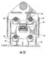
- Figs. 5A, 5B, and 5C show the elastomeric shear members and the elastomeric compression member acting as vibration/tension load absorbing elements when vibratory and tension loads are being applied;
- Figs. 6A, 6B, and 6C are side views of the elastomeric shear members and the elastomeric compression member illustrated in Figs. 5A, 5B and 5C, taken along line 6-6 in Fig. 5A;
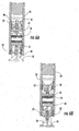
- Fig. 7 is a detail sectional view of an alternate embodiment of the compression member of the present invention.
- Fig. 8 is a side view showing an alternate embodiment of the housing and the vibratory unit, and the location of the compression members therebetween;
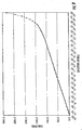
- Fig. 9 is a chart showing the relationship between increasing tension load and accompanying deflection in a typical rig utilizing the vibration/tension load absorbing features of the present invention.
- FIG. 1 illustrates a typical pile driving and extracting rig with which the vibration/tension load absorbing features of the present invention may be utilized.
- This rig includes a crane 10 having a boom 12 that is pivotally mounted on the crane 10.
- a support cable 14 extends upwardly through the boom 12 and over a pulley 16 at the top of the boom 12, and the end of the cable 14 supports a vibratory pile driver/extractor 18.
- the vibratory pile driver/extractor 18 includes a housing 20, and a vibrator 22 which is mounted within the housing 20 in a manner to be described in greater detail below.
- the crane 10 manipulates the vibratory pile driver/extractor 18 over a pile 24 so that the vibrator 22 can engage the upper end of the pile 24 as illustrated in Fig. 1.
- the cable 14 is then extended or retracted to raise or lower the vibratory pile driver/extractor 18, depending on whether the pile 24 is being extracted from the ground or driven into the ground, and the vibration imparted to the pile by the vibrator 22 assists in driving the pile 24 into the ground or extracting the pile 24 out of the ground.
- the vibratory pile driver/extractor 18 can be directly supported by equipment other than a crane 10.
- the vibratory pile driver/extractor 18 could be mounted directly on the "stick" of an excavator (not shown), or directly supported on a forklift (not shown).
- the vibratory/tension load suppressor 23 portion of the vibratory pile driver/extractor 18 is best seen in Figs. 2 and 3.
- the vibrator 22 includes an upper plate 26, and the housing 20 includes two generally flat sidewalls 28 that extend vertically in spaced parallel relation to one another.
- the upper plate 26 includes a vertically extending center wall portion 30 that extends upwardly into the spacing between the housing sidewalls 28.
- the center wall portion 30 of the upper plate 26 of the vibrator 22 is mounted to the sidewalls 28 of the housing 20 by a plurality of shear-type vibration/tension load absorbing elements 32, which in the preferred embodiment of the present invention are in the form of generally cylindrical elastomeric elements that extend on their horizontal axes between the center wall portion 30 of the upper plate 26 and the sidewalls 28.
- Each of the shear-type vibration/tension load absorbing elements 32 includes a pair of mounting plates 34 located at the ends thereof so that one end of the vibration/tension load absorbing elements 32 can be mounted to one of the side walls 28, and the other end can be mounted to the center wall portion 30. It will be understood that the number, location, and configuration of the shear-type vibration/tension load absorbing elements 32 can be varied depending on the particular application of the vibratory pile driver/extractor 18, and the loads likely to be encountered by the vibratory pile driver/extractor 18.
- At least one compression-type vibration/tension load absorbing element 36 is mounted on top of a first compression plate 38 that is mounted on one or both of the housing sidewalls 28 to extend therebetween.
- the compression-type vibration/tension load absorbing element 36 is a conventional wing-type compression element that is mounted on the first compression plate 38 by a pair of L-shaped brackets 40 that extend over the horizontal wings of the compression-type vibration/tension load absorbing element 36. While it is believed that the wing-type compression vibration/tension load absorbing elements 36 will work best in most applications of the vibration absorbing apparatus of the present invention, it is to be understood that other types of compression-type vibration absorbers could also be used, if desired.
- the compression-type vibration/tension load absorbing element 36 is mounted on the first compression plate 38 so as to be positioned directly beneath a second compression plate 42 which is fixed to a mounting plate 44 which, in turn, is mounted on the center wall portion 30.
- the bottom face of the second compression plate 42 may be configured to have a curved center portion 46 and two flat end portions 48.
- the vibratory pile driver/extractor 18 is subjected to vibratory loads generated by the conventional rotating eccentrics (not shown) within the vibrator 22 and, more importantly, the vibratory pile driver/extractor 18 is subjected to very high tension loads created by the difficulty of raising and extracting a sunken pile from the ground.
- Figs. 5A-5C which are sectional views taken along a vertical plane of a front view, and Figs.
- 6A-6C which are corresponding sectional views taken along a vertical plane of a side view, illustrate the interaction of the shear-type vibration absorber elements 32 and the compression-type vibration/tension load absorbing element 36 when the vibratory pile driver/extractor 18 is subjected to these loads.
- Figs. 5A and 6A illustrate the vibratory pile driver/extractor 18 under a no-tension-load condition.
- the shear-type vibration/tension load absorbing elements 32 extend generally horizontally between the sidewalls 28 of the housing 20 and the center wall portion 30 of the vibrator upper plate 26. Since there is essentially no significant tension load, there is no significant deflection of the shear-type vibration/tension load absorbing elements 32. It will also be noted that in this condition the second compression plate 42 is positioned to be spaced above and out of contact with the compression-type vibration/tension load absorbing element 36.
- the tension load increases, and the shear-type vibration/tension load absorbing elements 32 begin to deform in a vertical direction and thereby absorb the vibration and tension loads by shear-strain as center wall portion 30 the upper plate 26 of the vibrator 22 moves vertically downward within the spacing between the sidewalls 28 of the housing 20, all in a manner well known in the art.
- This vibration and tension load absorbing action will continue from the no-tension-load condition until the tension load reaches a predetermined level, and, in accordance with the present invention, when the tension load reaches that predetermined level, the vertical movement of the center wall portion 30 of the vibrator 22 relative to the sidewalls 28 of the housing 20 will have increased to a point that is illustrated in Figs. 5B and 6B.
- the shear-type vibration/tension load absorbing elements 32 are significantly deformed in a vertical direction, and the second compression plate 42 makes initial contact with the top surface of the compression-type vibration/tension load absorbing element 36, as best illustrated in Fig. 5B.
- the shear-type vibration/tension load absorbing elements 32 will continue to absorb vibration and tension loads by shear-strain and further deflection in a vertical direction, and, in addition, the compression-type vibration/tension load absorbing element 36 is now compressed by the vertical movement of the first compression plate 38 toward the second compression plate 42, whereby the compression-type vibration/tension load absorbing element 36 provides significant tension load absorbing capability in addition to the tension load absorbing action of the shear-type vibration/tension load absorbing elements 32.
- both the second compression plate 42 and the mounting brackets 40 are made of metal, and when the tension load reaches the high level at which the second compression plate 42 makes contact with the mounting brackets 40, an audible clanging sound is generated as metal strikes metal.
- This audible sound constitutes a warning to the operator of the rig that the vibratory pile driver/extractor 18 has reached the maximum tension load that it can reasonably absorb, whereby the operator can make appropriate adjustments to the operation of the rig to decrease the tension load on the vibratory pile driver/extractor 18.
- the compression-type vibration/tension load absorbing element 36 is mounted on the first compression plate 38 but it will be understood that the compression-type vibration absorber could just as readily be mounted on the bottom surface of the second compression plate 42.
- the first compression plate 38 would have a configuration like that described above for the second compression plate 42.
- the preferred configuration of the second compression plate 42 includes the curved center portion 46 as described above and as illustrated in the drawings, the second compression plate 42 could also be formed with a flat surface configuration if desired.
- the present invention provides a unique vibration and tension load absorbing capability that utilizes traditional shear-strain vibration and tension load absorption offered by known shear-type vibration/tension load absorber elements operating in concert with a compression-type vibration/tension load absorber element that is uniquely capable of absorbing high tension loads that may be encountered when the tension loads exceed a predetermined level.
- This interplay is illustrated by a typical chart shown in Fig. 9, which is exemplary only, wherein the Y-coordinate is the tension load in tons, and the X-coordinate represents the vertical deflection of the vibrator 22 relative to the housing 20 utilizing the vibration and tension load absorbing arrangement of the present invention.
- Fig. 9 which is exemplary only, wherein the Y-coordinate is the tension load in tons, and the X-coordinate represents the vertical deflection of the vibrator 22 relative to the housing 20 utilizing the vibration and tension load absorbing arrangement of the present invention.
- Fig. 7 illustrates an alternate embodiment of the present invention in which a conventional D-shaped compression-type vibration/tension load absorbing element 36 is used.
- the compression-type vibration/tension load absorbing element 36 is mounted on the first compression plate 38 by a bolt 50, and the top of the D-shaped compression-type vibration/tension load absorbing element 36 is formed with an opening that is slightly larger than the head of the bolt 50. Accordingly, in this embodiment, when the vibration/tension load absorbing element 36 reaches its fully compressed condition, the head of the bolt 50 will pass upwardly through the opening and it will be struck by the bottom surface of the second compression plate 42 to create a audible clanging sound similar to the clanging sound described above.
- Fig. 8 one suitable alternative embodiment of the present invention is illustrated in Fig. 8.
- two compression-type vibration/tension load absorbing elements 36 are mounted on two first compression plates 38, and two second compression plates 42 are mounted on the vibrator 22 above the compression-type vibration/tension load absorbing elements 36.
- the compression of the compression-type vibration/tension load absorbing elements 36 between the first compression plates 38 and the second compression plates 42 is identical to that described above, except that in this embodiment there are multiple compression-type vibration absorber elements 36.
Landscapes
- Engineering & Computer Science (AREA)
- Life Sciences & Earth Sciences (AREA)
- General Life Sciences & Earth Sciences (AREA)
- Mining & Mineral Resources (AREA)
- Paleontology (AREA)
- Civil Engineering (AREA)
- General Engineering & Computer Science (AREA)
- Structural Engineering (AREA)
- Placing Or Removing Of Piles Or Sheet Piles, Or Accessories Thereof (AREA)
- Vibration Prevention Devices (AREA)
Abstract

Description
- The present invention relates generally to devices or rigs for driving piles and the like into the ground and for extracting piles that have been driven into the ground, and more particularly to rigs of this type that are provided with a vibration/tension load suppressor for absorbing vibration and tension loads generated by the driving and extracting operations.
- Vibratory pile driver/extractors which are used for driving and extracting piles and the like generally include a vibratory unit that is connected to a housing which in turn is connected to a cable or other support that lowers and lifts the housing and vibratory unit during the driving and extracting operations, respectively. The vibratory unit is connected to the pile and usually includes rotating eccentrics that impart vibrations to the pile to assist in driving and extracting the pile.
- During driving operations, the housing and vibratory unit are positioned on top of the pile itself and to a large extent are supported thereby. Therefore, there is little or no tension load on the cable as it lowers the housing and vibratory unit while the pile is driven into the ground. However, during pile extracting operations, the cable must not only bear the dead weight of the housing and vibratory unit, it is also subjected to the high tension loads required to extract the pile from the ground. Vibration and tension loads generated during the pile extraction operation can damage the supporting cable and hoisting machinery if the vibration and tension loads are not properly absorbed.
- In early designs, springs were provided as vibration/tension load absorbers, but because the tension loads varied so much, depending on whether the rig was driving or extracting piles, it was necessary to manually adjust the stiffness of the springs each time the rig changed from pile driving and pile extracting operations; and vice versa. This arrangement had the major disadvantage of being both time consuming and labor intensive.
- Another vibration/tension load absorbing arrangement is disclosed in Herz
U.S. Patent No. 3,502,160 . To avoid the problem of having to manually adjust the vibration/tension load absorbing springs, this patent utilizes two different sets of compression springs acting between a yoke and the vibratory unit or body, with one set having a greater stiffness than the other. The first set of weaker springs is connected between the yoke and the vibratory unit and is designed to maintain the yoke and the vibratory unit in fixed relation to one another during pile driving operations when there is little or no tension load on the cable. The second set of springs is stiffer than the first set, whereby during pile extracting operations the higher tension load on the cable is taken over by the set of stiffer springs when the tension load reaches a predetermined level. One disadvantage of this arrangement is that during pile driving operations, when there is generally some tension maintained in the cable, the vibration imparted to the cable is not absorbed since the first set of weaker springs maintains the yoke and the vibratory unit in fixed, rigid relation to one another. Additionally, during pile extracting operations, when the tension load exceeds the level at which the set of stiffer springs come into play, the first set of weaker springs become essentially non-functional and do not supplement the tension absorbing action of the set of stiffer springs. - Kniep
U.S. Patent No. 3,865,501 discloses a soil compactor that is operated by a vibratory unit carried on a housing by multiple compression springs that appears to be generally similar to the Herz arrangement, but since the Kniep patent does not include any detailed description of the compressions springs and their operation, it is not dear exactly how the multiple springs operate. - In White
U.S. Patent Nos. 5,117,925 and5,263,544 , pile driving and extracting rigs are disclosed which include multi-stage vibration/tension load absorbing elements for absorbing the vibration generated by a vibratory unit and tension loads. In these rigs, some of the vibration/tension load absorbing elements are connected between a base section and an intermediate section, and others of the vibration/tension load absorbing elements are connected between the intermediate section and a connection section. All of the vibration/tension load absorbing elements are in the form of horizontally extending elastomeric members arranged to absorb the loads by shear strain. The elastomeric members have varying thicknesses, and the vibration loads and tension loads are absorbed in stages. While these shear members are capable of absorbing loads encountered in conventional pile driving and pile extracting rigs, each member has a somewhat limited vibration and tension load absorbing capacity, and therefore in instances where the tension loads are very high, the number of vibration/tension load absorbing elements must be increased, all of which can increase the expense of the rig and the size of rig that must accommodate the increased number of shear members. - In accordance with the present invention, an apparatus for driving and extracting piles is provided which overcomes drawbacks of known devices of this type, and which provides an improved arrangement for absorbing vibration and tension loads associated with devices of this type.
- Briefly summarized, the present invention provides an apparatus for driving and extracting piles using a vibratory and tension force which includes a housing adapted to be connected to a support (e.g. a cable) that lifts and lowers the housing, the housing having at least one wall portion, and a vibratory unit adapted to be connected to a pile and generating a vibratory force for driving and extracting a pile. At least one first vibration/tension load absorbing element is connected between the wall portion of the housing and the vibratory unit, such first vibration/tension load absorbing element being formed of an elastomeric material for absorbing vibration and tension loads by shear strain and being positioned to absorb vibration generated by the vibratory unit and tension load applied by the support. At least one second vibration/tension load absorbing compression element formed of an elastomeric material is positioned between the housing and the vibratory unit to be compressed between the housing and the vibratory unit to absorb vibration generated by the vibratory unit and tension load generated by the support when the tension load applied by the support exceeds a predetermined level.
- In the preferred embodiment of the present invention, the housing has a first compression plate mounted thereon, and the vibratory unit has a second compression plate mounted thereon in spaced relation to the first compression plate so that the tension load applied by the support results in the first and second compression plates moving toward one another. The second vibration/tension load absorbing element is mounted on one of the first or second compression plates in the spacing between the first and second compression plates.
- The second vibration/tension load absorbing element can be positioned between the first and second compression plates to stop further movement of the first and second compression plates toward one another when the second vibration/tension load absorbing element is fully compressed by the first and second compression plates so that the second vibration/tension load absorbing element also acts as a stop when it is fully compressed.
- Preferably, the first vibration/tension load absorbing elements are constructed and arranged so that they will continue to absorb vibration by shear strain after the tension load applied by the support exceeds the predetermined level at which the second vibration/tension load absorbing element begins its vibration and tension load absorbing function.
- Also, in accordance with one feature of the present invention, a rigid member may be mounted on one of the first and second compression plates to extend in a direction toward the other of the first and second compression plates. The extending length of the rigid member is substantially equal to the maximum height of the second vibration/tension load absorbing element when it is fully compressed between the first and second compression, so that when the second vibration/tension load absorbing element is fully compressed the rigid element is engaged by one of the first and second compression plates and acts as a stop to prevent further movement of the first and second compression plates toward one another. The rigid element and the first and second compression plates are preferably made of metal so that a sound is generated by the engagement of the rigid member with one of the first and second compression plates. The rigid element may be a bolt with a head, and the second vibration absorbing member may be held in place by the bolt and may be formed with an opening through which the head of the bolt can extend to engage one of the first and second compression plates when the second vibration/tension load absorbing element is fully compressed.
- In another embodiment, the rigid member may be a bracket and the second vibration/tension load absorbing element may be held in place by the bracket being secured to one of the first and second compression plates. The height of the bracket above the compression plate to which it is secured is substantially equal to the maximum height of the second vibration/tension load absorbing element when it is fully compressed between the first and second compression so that when the second vibration/tension load absorbing element is fully compressed the bracket is engaged by one of the first and second compression plates and acts as a stop to prevent further movement of the first and second compression plates toward one another. In this embodiment, the bracket and the first and second compression plates are preferably made of metal, whereby a sound is generated by the engagement of the bracket with one of the first and second compression plates.
- It is preferred that the plurality of first elastomeric vibration/tension load absorbing elements be mounted between the wall portion of the housing and the vibratory unit, and that each such first elastomeric vibration/tension load absorbing element extend generally horizontally when there is no tension load imposed thereon and distorts vertically under the influence of the shear strain.
- The present invention also includes a method of absorbing the vibration and tension loads generated by a vibratory unit carried in a housing and connected to a pile for driving and extracting the pile. The method includes the steps of raising and lowering the housing and the vibratory unit using a support; absorbing the vibration generated by the vibratory unit and absorbing the tension load applied by the support utilizing shear strain; and absorbing the vibration generated by the vibratory unit and absorbing the tension load applied by the support using an elastomeric compression element positioned to be compressed between the vibratory unit and the housing whenever the tension load generated by the support exceeds a predetermined level. This method may also include the step of generating an audible sound of metal engaging metal when the compression element positioned between the vibratory unit and the housing is fully compressed by the tension load.
- Further features, embodiments, and advantages of the present invention will become apparent from the following detailed description with reference to the drawings, wherein:
- Fig. 1 is a general view of a rig for driving and extracting piles which embodies the present invention;
- Fig. 2 is a perspective view of the vibration/tension load suppressor of the rig;
- Fig. 3 is an exploded view, partially in section, of the vibration/tension load suppressor illustrated in Fig. 2;
- Fig. 4 is a side elevational view taken through line 4-4 in Fig. 5A showing the connection of the shear-type elastomeric members between the housing and the vibratory unit of the rig;
- Figs. 5A, 5B, and 5C show the elastomeric shear members and the elastomeric compression member acting as vibration/tension load absorbing elements when vibratory and tension loads are being applied;
- Figs. 6A, 6B, and 6C are side views of the elastomeric shear members and the elastomeric compression member illustrated in Figs. 5A, 5B and 5C, taken along line 6-6 in Fig. 5A;
- Fig. 7 is a detail sectional view of an alternate embodiment of the compression member of the present invention;
- Fig. 8 is a side view showing an alternate embodiment of the housing and the vibratory unit, and the location of the compression members therebetween; and
- Fig. 9 is a chart showing the relationship between increasing tension load and accompanying deflection in a typical rig utilizing the vibration/tension load absorbing features of the present invention.
- Looking now in greater detail at the accompanying drawings, Fig. 1 illustrates a typical pile driving and extracting rig with which the vibration/tension load absorbing features of the present invention may be utilized. This rig includes a
crane 10 having aboom 12 that is pivotally mounted on thecrane 10. Asupport cable 14 extends upwardly through theboom 12 and over apulley 16 at the top of theboom 12, and the end of thecable 14 supports a vibratory pile driver/extractor 18. The vibratory pile driver/extractor 18 includes ahousing 20, and avibrator 22 which is mounted within thehousing 20 in a manner to be described in greater detail below. - In operation, the
crane 10 manipulates the vibratory pile driver/extractor 18 over apile 24 so that thevibrator 22 can engage the upper end of thepile 24 as illustrated in Fig. 1. Thecable 14 is then extended or retracted to raise or lower the vibratory pile driver/extractor 18, depending on whether thepile 24 is being extracted from the ground or driven into the ground, and the vibration imparted to the pile by thevibrator 22 assists in driving thepile 24 into the ground or extracting thepile 24 out of the ground. - While the rig illustrated in Fig. 1 and described above is the most common arrangement for supporting and manipulating the vibratory pile driver/
extractor 18, it is also well known in the art that the vibratory pile driver/extractor 18 can be directly supported by equipment other than acrane 10. For example, the vibratory pile driver/extractor 18 could be mounted directly on the "stick" of an excavator (not shown), or directly supported on a forklift (not shown). - The vibratory/
tension load suppressor 23 portion of the vibratory pile driver/extractor 18 is best seen in Figs. 2 and 3. Thevibrator 22 includes anupper plate 26, and thehousing 20 includes two generallyflat sidewalls 28 that extend vertically in spaced parallel relation to one another. Theupper plate 26 includes a vertically extendingcenter wall portion 30 that extends upwardly into the spacing between thehousing sidewalls 28. - As best seen in Figs. 3 and 4, the
center wall portion 30 of theupper plate 26 of thevibrator 22 is mounted to thesidewalls 28 of thehousing 20 by a plurality of shear-type vibration/tensionload absorbing elements 32, which in the preferred embodiment of the present invention are in the form of generally cylindrical elastomeric elements that extend on their horizontal axes between thecenter wall portion 30 of theupper plate 26 and thesidewalls 28. Each of the shear-type vibration/tensionload absorbing elements 32 includes a pair of mountingplates 34 located at the ends thereof so that one end of the vibration/tensionload absorbing elements 32 can be mounted to one of theside walls 28, and the other end can be mounted to thecenter wall portion 30. It will be understood that the number, location, and configuration of the shear-type vibration/tensionload absorbing elements 32 can be varied depending on the particular application of the vibratory pile driver/extractor 18, and the loads likely to be encountered by the vibratory pile driver/extractor 18. - In addition to the shear-type vibration/tension
load absorbing elements 32, and as best seen in Figs. 3 and 5A, at least one compression-type vibration/tensionload absorbing element 36 is mounted on top of afirst compression plate 38 that is mounted on one or both of the housing sidewalls 28 to extend therebetween. In the preferred embodiment of the present invention that is illustrated in Figs. 1-6, the compression-type vibration/tensionload absorbing element 36 is a conventional wing-type compression element that is mounted on thefirst compression plate 38 by a pair of L-shapedbrackets 40 that extend over the horizontal wings of the compression-type vibration/tensionload absorbing element 36. While it is believed that the wing-type compression vibration/tensionload absorbing elements 36 will work best in most applications of the vibration absorbing apparatus of the present invention, it is to be understood that other types of compression-type vibration absorbers could also be used, if desired. - The compression-type vibration/tension
load absorbing element 36 is mounted on thefirst compression plate 38 so as to be positioned directly beneath asecond compression plate 42 which is fixed to a mountingplate 44 which, in turn, is mounted on thecenter wall portion 30. For a purpose to be described in greater detail below, the bottom face of thesecond compression plate 42 may be configured to have acurved center portion 46 and twoflat end portions 48. - As explained in greater detail above, when the pile driving and extracting rig is used to extract piles, the vibratory pile driver/
extractor 18 is subjected to vibratory loads generated by the conventional rotating eccentrics (not shown) within thevibrator 22 and, more importantly, the vibratory pile driver/extractor 18 is subjected to very high tension loads created by the difficulty of raising and extracting a sunken pile from the ground. Figs. 5A-5C, which are sectional views taken along a vertical plane of a front view, and Figs. 6A-6C, which are corresponding sectional views taken along a vertical plane of a side view, illustrate the interaction of the shear-typevibration absorber elements 32 and the compression-type vibration/tensionload absorbing element 36 when the vibratory pile driver/extractor 18 is subjected to these loads. - More specifically, Figs. 5A and 6A illustrate the vibratory pile driver/
extractor 18 under a no-tension-load condition. In this condition, it will be noted that the shear-type vibration/tensionload absorbing elements 32 extend generally horizontally between thesidewalls 28 of thehousing 20 and thecenter wall portion 30 of the vibratorupper plate 26. Since there is essentially no significant tension load, there is no significant deflection of the shear-type vibration/tensionload absorbing elements 32. It will also be noted that in this condition thesecond compression plate 42 is positioned to be spaced above and out of contact with the compression-type vibration/tensionload absorbing element 36. - However, when the rig begins to extract a
pile 24 from the ground; the tension load increases, and the shear-type vibration/tensionload absorbing elements 32 begin to deform in a vertical direction and thereby absorb the vibration and tension loads by shear-strain ascenter wall portion 30 theupper plate 26 of thevibrator 22 moves vertically downward within the spacing between thesidewalls 28 of thehousing 20, all in a manner well known in the art. This vibration and tension load absorbing action will continue from the no-tension-load condition until the tension load reaches a predetermined level, and, in accordance with the present invention, when the tension load reaches that predetermined level, the vertical movement of thecenter wall portion 30 of thevibrator 22 relative to thesidewalls 28 of thehousing 20 will have increased to a point that is illustrated in Figs. 5B and 6B. At this point, the shear-type vibration/tensionload absorbing elements 32 are significantly deformed in a vertical direction, and thesecond compression plate 42 makes initial contact with the top surface of the compression-type vibration/tensionload absorbing element 36, as best illustrated in Fig. 5B. If the tension load increases beyond this predetermined level, the shear-type vibration/tensionload absorbing elements 32 will continue to absorb vibration and tension loads by shear-strain and further deflection in a vertical direction, and, in addition, the compression-type vibration/tensionload absorbing element 36 is now compressed by the vertical movement of thefirst compression plate 38 toward thesecond compression plate 42, whereby the compression-type vibration/tensionload absorbing element 36 provides significant tension load absorbing capability in addition to the tension load absorbing action of the shear-type vibration/tensionload absorbing elements 32. - This dual action of the shear-type vibration/tension
load absorbing elements 32 and the compression-type vibration/tensionload absorbing element 36 will continue until the tension load exceeds the predetermined level to such an extent that the compression-type vibration/tensionload absorbing element 36 is fully compressed between thefirst compression plate 38 and thesecond compression plate 42 as illustrated in Figs. 5C and 6C. At this point, theflat end portions 48 of the lower face of thesecond compression plate 42 contact the upper surface of the two mountingbrackets 40 which thereby prevents any further relative movement of thevibrator 22 relative to thehousing 20. In accordance with one feature of the present invention, both thesecond compression plate 42 and the mountingbrackets 40 are made of metal, and when the tension load reaches the high level at which thesecond compression plate 42 makes contact with the mountingbrackets 40, an audible clanging sound is generated as metal strikes metal. This audible sound constitutes a warning to the operator of the rig that the vibratory pile driver/extractor 18 has reached the maximum tension load that it can reasonably absorb, whereby the operator can make appropriate adjustments to the operation of the rig to decrease the tension load on the vibratory pile driver/extractor 18. - In the preferred embodiment of the present invention the compression-type vibration/tension
load absorbing element 36 is mounted on thefirst compression plate 38 but it will be understood that the compression-type vibration absorber could just as readily be mounted on the bottom surface of thesecond compression plate 42. In that arrangement, thefirst compression plate 38 would have a configuration like that described above for thesecond compression plate 42. It will be understood that while the preferred configuration of thesecond compression plate 42 includes thecurved center portion 46 as described above and as illustrated in the drawings, thesecond compression plate 42 could also be formed with a flat surface configuration if desired. - It will be appreciated from the description above that the present invention provides a unique vibration and tension load absorbing capability that utilizes traditional shear-strain vibration and tension load absorption offered by known shear-type vibration/tension load absorber elements operating in concert with a compression-type vibration/tension load absorber element that is uniquely capable of absorbing high tension loads that may be encountered when the tension loads exceed a predetermined level. This interplay is illustrated by a typical chart shown in Fig. 9, which is exemplary only, wherein the Y-coordinate is the tension load in tons, and the X-coordinate represents the vertical deflection of the
vibrator 22 relative to thehousing 20 utilizing the vibration and tension load absorbing arrangement of the present invention. In Fig. 9, it will be noted that as long as the tension load remains beneath a predetermined level, there is a generally straight line relationship between the tension load and the deflection, which results from the vibration and tension load absorbing action of the shear-type vibration/tensionload absorbing elements 32. However, when the tension load reaches a predetermined level, which is approximately 125 tons in the illustrative chart shown in Fig. 9, the compression-type vibration/tensionload absorbing element 36 comes into play, and the straight line relationship between the load and deflection changes significantly and assumes a much steeper curve indicating that substantial load increases can be absorbed by the compression-type vibration/tensionload absorbing element 36 with only a small degree of deflection. - Fig. 7 illustrates an alternate embodiment of the present invention in which a conventional D-shaped compression-type vibration/tension
load absorbing element 36 is used. The compression-type vibration/tensionload absorbing element 36 is mounted on thefirst compression plate 38 by abolt 50, and the top of the D-shaped compression-type vibration/tensionload absorbing element 36 is formed with an opening that is slightly larger than the head of thebolt 50. Accordingly, in this embodiment, when the vibration/tensionload absorbing element 36 reaches its fully compressed condition, the head of thebolt 50 will pass upwardly through the opening and it will be struck by the bottom surface of thesecond compression plate 42 to create a audible clanging sound similar to the clanging sound described above. - It will be appreciated that in some applications, particularly where there are very high tension loads to be encountered, it may be necessary or desirable to increase the number of compression-type vibration/tension
load absorbing elements 36, and one suitable alternative embodiment of the present invention is illustrated in Fig. 8. In this embodiment, two compression-type vibration/tensionload absorbing elements 36 are mounted on twofirst compression plates 38, and twosecond compression plates 42 are mounted on thevibrator 22 above the compression-type vibration/tensionload absorbing elements 36. In this embodiment of the present invention, the compression of the compression-type vibration/tensionload absorbing elements 36 between thefirst compression plates 38 and thesecond compression plates 42 is identical to that described above, except that in this embodiment there are multiple compression-typevibration absorber elements 36. - In view of the aforesaid written description of the present invention, it will be readily understood by those persons skilled in the art that the present invention is susceptible of broad utility and application. Many embodiments and adaptations of the present invention other than those herein described, as well as many variations, modifications, and equivalent arrangements, will be apparent from or reasonably suggested by the present invention and the foregoing description thereof, without departing from the substance or scope of the present invention. Accordingly, while the present invention has been described herein in detail in relation to preferred embodiments, it is to be understood that this disclosure is only illustrative and exemplary of the present invention and is made merely for purposes of providing a full and enabling disclosure of the invention. The foregoing disclosure is not intended nor is to be construed to limit the present invention or otherwise to exclude any such other embodiments, adaptations, variations, modifications and equivalent arrangements, the present invention being limited only by the claims appended hereto and the equivalents thereof.
Claims (17)
- Apparatus for driving and extracting piles using a vibratory and tension force, such apparatus comprising:(a) a housing adapted to be connected to a support that lifts and lowers the housing and having at least one wall portion;(b) a vibratory unit adapted to be connected to a pile and generating a vibratory force for driving and extracting a pile;(c) at least one first vibration/tension load absorbing element connected between the wall portion of the housing and the vibratory unit, such first vibration/tension load absorbing element being formed of an elastomeric material for absorbing vibration and tension loads by shear strain and being positioned to absorb by shear stain the vibration generated by the vibratory unit and tension load applied by the support; and(d) at least one second vibration/tension load absorbing compression element formed of an elastomeric material and positioned between the housing and the vibratory unit to be compressed between the housing and the vibratory unit to absorb vibration generated by the vibratory unit and to absorb the tension load generated by the support when the tension load generated by the support exceeds a predetermined level.
- Apparatus for driving and extracting piles using a vibratory and tension load force as defined in daim 1 wherein the first vibration/tension load absorbing element is constructed and arranged to absorb vibration and tension loads by shear strain after the tension load applied by the support exceeds the predetermined level.
- Apparatus for driving and extracting piles using a vibratory and tension load force as defined in claim 1 wherein the housing has a first compression plate mounted thereon, wherein the vibratory unit has a second compression plate mounted thereon in spaced relation to the first compression plate so that the tension load applied by the support results in the first and second compression plates moving toward one another, and wherein the second vibration/tension load absorbing element is mounted on one of the first and second compression plates in the spacing between the first and second compression plates.
- Apparatus for driving and extracting piles using a vibratory and tension load force as defined in claim 3 wherein the second vibration/tension load absorbing element is positioned between the first and second compression plates to stop further movement of the first and second compression plates toward one another when the second vibration/tension load absorbing element is fully compressed by the first and second compression plates, whereby the second vibration/tension load absorbing element also acts as a stop when it is fully compressed.
- Apparatus for driving and extracting piles using a vibratory and tension load force as defined in claim 3 wherein a rigid member is mounted on one of the first and second compression plates to extend in a direction toward the other of the first and second compression plates, and wherein the extending length of the rigid member is substantially equal to the maximum height of the second vibration/tension load absorbing element when it is fully compressed between the first and second compression plates, whereby when the second vibration/tension load absorbing element is fully compressed the rigid element is engaged by one of the first and second compression plates and acts as a stop to prevent further movement of the first and second compression plates toward one another.
- Apparatus for driving and extracting piles using a vibratory and tension load force as defined in daim 5 wherein the rigid element and the first and second compression plates are made of metal, whereby a sound is generated by the engagement of the rigid member with one of the first and second compression plates.
- Apparatus for driving and extracting piles using a vibratory and tension load force as defined in claim 6 wherein the rigid member is a bolt, and wherein the second vibration absorbing member is held in place by the bolt and is formed with an opening through which the head of the bolt can extend to engage one of the first and second compression plates when the second vibration/tension load absorbing element is fully compressed.
- Apparatus for driving and extracting piles using a vibratory and tension load force as defined in daim 6 wherein the rigid member is a bracket, and wherein the second vibration/tension load absorbing element is held in place by the bracket being secured to one of the first and second compression plates, and wherein the height of the bracket above the compression plate to which it is secured is substantially equal to the maximum height of the second vibration/tension load absorbing element when it is fully compressed between the first and second compression, whereby when the second vibration/tension load absorbing element is fully compressed the bracket is engaged by one of the first and second compression plates and acts as a stop to prevent further movement of the first and second compression plates toward one another.
- Apparatus for driving and extracting piles using a vibratory and tension load force as defined in claim 8 wherein the bracket and the first and second compression plates are made of metal, whereby a sound is generated by the engagement of the bracket with one of the first and second compression plates.
- Apparatus for driving and extracting piles using a vibratory and tension load force as defined in claim 1 wherein a plurality of first elastomeric vibration/tension load absorbing elements are mounted between the wall portion of the housing and the vibratory unit, and wherein each such first elastomeric vibration/tension load absorbing element extends generally horizontally when there is no significant tension load imposed thereon and distorts vertically under the influence of the shear strain.
- Apparatus for driving and extracting piles using a vibratory and tension force, such apparatus comprising:(a) a housing adapted to be connected to a support cable that lifts and lowers the housing and having at least one wall portion, the housing being provided with a first compression plate;(b) a vibratory unit adapted to be connected to a pile and generating a vibratory force for driving and extracting a pile, the vibratory unit including a second compression plate that is positioned in spaced parallel relation to the first compression plate;(c) a plurality of first vibration/tension load absorbing elements connected to and extending generally horizontally between the wall portion of the housing and the vibratory unit, such first vibration/tension load absorbing elements being formed of an elastomeric material for absorbing vibration and for absorbing tension loads by shear strain and being positioned to absorb by shear strain the vibration generated by the vibratory unit and to absorb the tension load applied by the support cable before and after such tension load reaches a predetermined level;(d) at least one second vibration/tension load absorbing compression element formed of an elastomeric material and positioned between the first compression plate on the housing and second compression plate on the vibratory unit to be compressed between the first and second compression plates to absorb vibration generated by the vibratory unit and tension load applied by the support only when the tension load applied by the support cable exceeds the predetermined level; and(e) a rigid member mounted on one of the first and second compression plates to extend in a direction toward the other of the first and second compression plates, the extending length of the rigid member being substantially equal to the maximum height of the second vibration/tension load absorbing element when it is fully compressed between the first and second compression plates, whereby when the second vibration/tension load absorbing element is fully compressed the rigid element is engaged by the other of the first and second compression plates and acts as a stop to prevent further movement of the first and second compression plates toward one another.
- Apparatus for driving and extracting piles using a vibratory and tension force, such apparatus comprising:(a) a housing adapted to be connected to a support cable that lifts and lowers the housing and having at least one wall portion;(b) a vibratory unit adapted to be connected to a pile and generating a vibratory force for driving and extracting a pile;(c) a plurality of elastomeric first shear-type vibration/tension load absorbing elements connected to and extending generally horizontally between the wall portion of the housing and the vibratory unit, such first vibration/tension load absorbing element being formed of an elastomeric material for absorbing vibration and tension loads by shear strain and being positioned to absorb vibration generated by the vibratory unit and tension load applied by the support cable when the tension load applied by the support cable is above and below a predetermined level; and(d) at least one second vibration/tension load absorbing compression element formed of an elastomeric material and positioned between the housing and the vibratory unit to be compressed between the housing and the vibratory unit to absorb vibration generated by the vibratory unit and to absorb tension load applied by the support cable only when the tension load generated by the support cable exceeds a predetermined level.
- Apparatus for driving and extracting piles using a vibratory and tension force, such apparatus comprising:(a) a housing adapted to be connected to a support cable that lifts and lowers the housing and having at least one wall portion;(b) a vibratory unit adapted to be connected to a pile and generating a vibratory force for driving and extracting a pile;(c) a plurality of first shear-type vibration/tension load absorbing elements connected to and extending generally horizontally between the wall portion of the housing and the vibratory unit, such first vibration/tension load absorbing elements being formed of an elastomeric material for permitting relative movement of the housing in a direction toward and away from the vibratory unit as a result of the tension load applied by the support cable; and(d) at least one second vibration/tension load absorbing compression element formed of an elastomeric material and positioned between the housing and the vibratory unit to be compressed between the housing and the vibratory unit to absorb vibration and tension loads generated by the vibratory unit and the support only when the distance between the housing and the vibratory unit resulting from the relative movement thereof is less than a predetermined distance.
- A method of absorbing the vibration and tension loads generated by a vibratory unit carried in the housing and connected to a pile for driving and extracting the pile, said method comprising the steps of:(a) raising and lowering the housing and the vibratory unit using a support;(b) absorbing the vibration generated by the vibratory unit and absorbing the tension load generated by the support utilizing shear strain; and(c) absorbing the vibration generated by the vibratory unit and absorbing the tension load generated by the support using an elastomeric compression element positioned to be compressed between the vibratory unit and the housing whenever the tension load generated by the support exceeds a predetermined level.
- A method of absorbing the vibration and tension loads as defined in claim 14, wherein the method includes the step of generating an audible sound of metal engaging metal when the compression element positioned between the vibratory unit and the housing is fully compressed by the tension load.
- A method of absorbing the vibration and tension loads as defined in claim 14, wherein the step of absorbing the vibration generated by the vibratory unit and absorbing the tension load generated by the support utilizing shear strain continues after the tension load exceeds the predetermined level.
- A method of absorbing the vibration and tension loads generated by a vibratory unit carried in the housing and connected to a pile for driving and extracting the pile, said method comprising the steps of:(a) raising and lowering the housing and the vibratory unit using a support;(b) absorbing the vibration generated by the vibratory unit and the tension load generated by the support using shear-type vibration/tension load absorbing elements;(c) positioning opposed compression plates on the housing and the vibratory unit so that they move toward and away from one another during the relative movement of the housing and the vibratory unit; and(d) absorbing the vibration generated by the vibratory unit and the tension load applied by the support using an elastomeric compression element positioned to be compressed between the opposed compression plates when the distance between the opposed compression plates reaches a predetermined minimum distance.
Applications Claiming Priority (1)
| Application Number | Priority Date | Filing Date | Title |
|---|---|---|---|
| US11/116,040 US7080958B1 (en) | 2005-04-27 | 2005-04-27 | Vibratory pile driver/extractor with two-stage vibration/tension load suppressor |
Publications (2)
| Publication Number | Publication Date |
|---|---|
| EP1717376A1 true EP1717376A1 (en) | 2006-11-02 |
| EP1717376B1 EP1717376B1 (en) | 2010-07-28 |
Family
ID=36687027
Family Applications (1)
| Application Number | Title | Priority Date | Filing Date |
|---|---|---|---|
| EP06008591A Active EP1717376B1 (en) | 2005-04-27 | 2006-04-26 | Vibratory pile driver/extractor with two-stage vibration/tension load suppressor |
Country Status (5)
| Country | Link |
|---|---|
| US (1) | US7080958B1 (en) |
| EP (1) | EP1717376B1 (en) |
| JP (1) | JP2006307637A (en) |
| CN (1) | CN1854396B (en) |
| DE (1) | DE602006015736D1 (en) |
Families Citing this family (24)
| Publication number | Priority date | Publication date | Assignee | Title |
|---|---|---|---|---|
| US7805865B2 (en) * | 2006-01-13 | 2010-10-05 | M-B-W, Inc. | Vibratory exciter unit for interchangeable connection to various vibratory tools |
| GB2447492A (en) * | 2007-03-15 | 2008-09-17 | Roxbury Ltd | A driving assembly, using both crowd and vibration driving forces |
| DE102007023963B4 (en) * | 2007-05-23 | 2014-01-02 | Abi Anlagentechnik-Baumaschinen-Industriebedarf Maschinenfabrik Und Vertriebsgesellschaft Mbh | Device for a vibration exciter |
| SE530501C2 (en) * | 2007-09-12 | 2008-06-24 | Bruno Vedin | Lifting and lowering device for e.g. pile, has outer casing held against inner casing by vibration damping device and provided with surfaces for centering and vertically positioning pile |
| US7669306B2 (en) | 2007-12-04 | 2010-03-02 | Waldemar Palka | Gear puller |
| US8474547B2 (en) * | 2008-10-14 | 2013-07-02 | Longyear Tm, Inc. | Isolation system for drilling systems |
| US8974771B2 (en) * | 2010-03-09 | 2015-03-10 | Penn-Century, Inc. | Apparatus and method for aerosol delivery to the lungs or other locations of the body |
| AU2011257942B2 (en) | 2010-05-28 | 2013-06-27 | A.C.N. 166 970 627 Pty Ltd | Vibration dampening device |
| NL2013871B1 (en) * | 2014-06-10 | 2016-05-03 | Cape Holland Holding B V | Vibrating device and method for placing a foundation element in a substrate. |
| EP3256648B1 (en) * | 2015-02-10 | 2019-10-30 | Ozkan, Aydin | A connection adapter |
| JP6059752B2 (en) * | 2015-03-03 | 2017-01-11 | 調和工業株式会社 | Anti-vibration rubber fittings for vibratory hammers and vibratory hammers |
| DE202015001862U1 (en) * | 2015-03-10 | 2016-06-13 | Liebherr-Werk Nenzing Gmbh | Jogger as an attachment for a construction machine |
| US10392871B2 (en) | 2015-11-18 | 2019-08-27 | American Piledriving Equipment, Inc. | Earth boring systems and methods with integral debris removal |
| US9957684B2 (en) | 2015-12-11 | 2018-05-01 | American Piledriving Equipment, Inc. | Systems and methods for installing pile structures in permafrost |
| EP3228392B1 (en) * | 2016-04-05 | 2019-08-28 | BAUER Maschinen GmbH | Vibration ram |
| US9926676B1 (en) * | 2016-09-28 | 2018-03-27 | Caterpillar Inc. | Locking mechanism for removable base plate on vibratory compactor |
| US10323377B2 (en) * | 2016-11-21 | 2019-06-18 | John Powers, III | Method and apparatus for emplacing steel columns |
| US10563370B2 (en) * | 2017-05-01 | 2020-02-18 | Terra Sonic International, LLC | Bolting adapter mechanism for sonic pile driving |
| US10815731B2 (en) * | 2017-11-20 | 2020-10-27 | John Powers, III | Method and apparatus for emplacing columns |
| US10246944B1 (en) * | 2017-11-20 | 2019-04-02 | John Powers, III | Method and apparatus for emplacing columns |
| US11274400B2 (en) * | 2018-07-25 | 2022-03-15 | Robel Bahnbaumaschinen Gmbh | Nail punching machine for driving in or pulling out rail spikes of a rail track |
| US11629474B2 (en) * | 2020-05-08 | 2023-04-18 | John L. White | Multi-stage suppressor for vibrating pile driver |
| US20230287644A1 (en) * | 2022-03-11 | 2023-09-14 | John L. White | Dampening assembly for vibratory pile drivers |
| KR102568362B1 (en) * | 2023-01-26 | 2023-08-17 | 김양형 | Casing pulling device that can be pulled out with low vibration and low noise using hydraulic pressure and vibrator |
Citations (6)
| Publication number | Priority date | Publication date | Assignee | Title |
|---|---|---|---|---|
| US3502160A (en) | 1968-12-16 | 1970-03-24 | Foster Co L B | Resilient yoke mounting for vibratory pile driver and extractor |
| US3865501A (en) | 1973-07-09 | 1975-02-11 | Int Tech Handelsonderneming En | Method and device for soil compacting |
| US4522304A (en) * | 1982-04-19 | 1985-06-11 | The Budd Company | Shock mount apparatus |
| DE4010357A1 (en) * | 1989-04-01 | 1990-10-04 | Anlagentech Baumasch Ind | Pile driving and pull-out hammer - has impact mass with lower end shaped as ramming piston, and cylindrical cavity in clamping jaw socket |
| US5117925A (en) | 1990-01-12 | 1992-06-02 | White John L | Shock absorbing apparatus and method for a vibratory pile driving machine |
| US5263544A (en) | 1990-01-12 | 1993-11-23 | American Piledriving Equipment, Inc. | Shock absorbing apparatus and method for a vibratory pile driving machine |
Family Cites Families (25)
| Publication number | Priority date | Publication date | Assignee | Title |
|---|---|---|---|---|
| US2975846A (en) | 1957-03-08 | 1961-03-21 | Jr Albert G Bodine | Acoustic method and apparatus for driving piles |
| US3362485A (en) | 1965-10-21 | 1968-01-09 | John J. Dyer Sr. | Post driver |
| US3394766A (en) | 1966-03-11 | 1968-07-30 | Lebelle Jean Louis | Apparatus for emplacing elongated rigid members into the soil selectively in a vibratory mode or in a percussive mode |
| US3909149A (en) | 1971-11-01 | 1975-09-30 | Allied Steel Tractor Prod Inc | Hydraulic vibratory compactor |
| US3828864A (en) | 1973-02-26 | 1974-08-13 | H & M Vibro Inc | Pile driver and extractor |
| DE2442367A1 (en) | 1974-09-04 | 1976-03-18 | Tracto Technik | HYDRAULICALLY DRIVEN VIBRATOR |
| US4143179A (en) | 1974-12-16 | 1979-03-06 | Fuji Polymer Industries, Co., Ltd. | Method of manufacturing a keyboard |
| US4061196A (en) | 1976-08-30 | 1977-12-06 | L. B. Foster Company | Resilient yoke mountings for vibratory pile drivers and extractors |
| US4100974A (en) | 1977-01-06 | 1978-07-18 | Pepe Charles R | Machine suspended from a crane or similar device for driving and extracting piling and the like |
| DE2823953C2 (en) | 1978-06-01 | 1985-01-24 | Tünkers Maschinenbau GmbH, 4030 Ratingen | Suspension device for vibrating bears on a load suspension device |
| US4616716A (en) | 1982-03-01 | 1986-10-14 | Allied Steel & Tractor Products, Inc. | Synchronous vibratory impact hammer |
| DE3303574C1 (en) | 1983-02-03 | 1984-09-06 | Josef-Gerhard 4030 Ratingen Tünkers | Vibration ram |
| EP0135479B1 (en) | 1983-09-19 | 1987-12-09 | Simson und Partner | Device for driving and extracting |
| US4645017A (en) | 1985-04-10 | 1987-02-24 | Bodine Albert G | Vibrational isolation system for sonic pile driver |
| US4819740A (en) | 1987-11-16 | 1989-04-11 | Vulcan Iron Works Inc. | Vibratory hammer/extractor |
| CN2054047U (en) * | 1989-05-24 | 1990-03-07 | 北京市机械施工公司 | Three-section combined spring vibration absorber |
| USD326857S (en) | 1989-10-24 | 1992-06-09 | Nippon Pneumatic Manufacturing Co., Ltd. | Vibrating pile driver |
| US5088565A (en) | 1990-03-23 | 1992-02-18 | J & M Hydraulic Systems, Inc. | Vibratory pile driver |
| JP2729969B2 (en) | 1990-03-29 | 1998-03-18 | 株式会社高橋エンジニアリング | Pile driver |
| US5167396A (en) | 1991-09-27 | 1992-12-01 | Dynasauer Corp. | Vibration isolating mount for vibratory pile driver and extractor |
| FI923880A0 (en) | 1991-09-30 | 1992-08-28 | Raunisto Airi | SLAGANORDNING. |
| US5725329A (en) | 1996-05-08 | 1998-03-10 | Chelminski; Stephen | Method, system and apparatus for driving and pulling pilings |
| US6543966B2 (en) * | 1997-07-25 | 2003-04-08 | American Piledriving Equipment, Inc. | Drive system for inserting and extracting elongate members into the earth |
| CN2344437Y (en) * | 1998-11-27 | 1999-10-20 | 徐州工程机械集团有限公司徐州工程机械研究所 | Vibration-reducing device for vibration hammer |
| GB2351111B (en) * | 1999-06-14 | 2002-01-23 | Expotech Ltd | A device for driving piles |
-
2005
- 2005-04-27 US US11/116,040 patent/US7080958B1/en active Active
-
2006
- 2006-04-26 CN CN200610077083XA patent/CN1854396B/en active Active
- 2006-04-26 EP EP06008591A patent/EP1717376B1/en active Active
- 2006-04-26 DE DE602006015736T patent/DE602006015736D1/en active Active
- 2006-04-27 JP JP2006122786A patent/JP2006307637A/en active Pending
Patent Citations (6)
| Publication number | Priority date | Publication date | Assignee | Title |
|---|---|---|---|---|
| US3502160A (en) | 1968-12-16 | 1970-03-24 | Foster Co L B | Resilient yoke mounting for vibratory pile driver and extractor |
| US3865501A (en) | 1973-07-09 | 1975-02-11 | Int Tech Handelsonderneming En | Method and device for soil compacting |
| US4522304A (en) * | 1982-04-19 | 1985-06-11 | The Budd Company | Shock mount apparatus |
| DE4010357A1 (en) * | 1989-04-01 | 1990-10-04 | Anlagentech Baumasch Ind | Pile driving and pull-out hammer - has impact mass with lower end shaped as ramming piston, and cylindrical cavity in clamping jaw socket |
| US5117925A (en) | 1990-01-12 | 1992-06-02 | White John L | Shock absorbing apparatus and method for a vibratory pile driving machine |
| US5263544A (en) | 1990-01-12 | 1993-11-23 | American Piledriving Equipment, Inc. | Shock absorbing apparatus and method for a vibratory pile driving machine |
Also Published As
| Publication number | Publication date |
|---|---|
| EP1717376B1 (en) | 2010-07-28 |
| JP2006307637A (en) | 2006-11-09 |
| US7080958B1 (en) | 2006-07-25 |
| DE602006015736D1 (en) | 2010-09-09 |
| CN1854396A (en) | 2006-11-01 |
| CN1854396B (en) | 2010-09-29 |
Similar Documents
| Publication | Publication Date | Title |
|---|---|---|
| US7080958B1 (en) | Vibratory pile driver/extractor with two-stage vibration/tension load suppressor | |
| CA2823796C (en) | Post driver with limited movement floating post anvil | |
| CN1736666A (en) | Breaker mounting bracket | |
| JPS6031970B2 (en) | Suspension device for a vibrating hammer hung on a lifting member | |
| CN105905843B (en) | The lifting device and lift truck of lift truck | |
| RU2536595C2 (en) | Construction machine and control method of construction machine | |
| CN205833232U (en) | A kind of reliable disintegrating apparatus | |
| US6257352B1 (en) | Rock breaking device | |
| CN103205959A (en) | Elastic support device, dynamic compactor lifting device and dynamic compactor | |
| CN205224038U (en) | Novel play pile pulling device | |
| KR102260704B1 (en) | Limitdamper for preventing impact | |
| CN220035379U (en) | Dynamic compactor with cantilever crane shock attenuation buffer function | |
| JP2991569B2 (en) | Double hammer type pile driving device | |
| NL9101294A (en) | METHOD AND APPARATUS FOR DRIVING PIPES | |
| CN212052744U (en) | Stable pile driver for traffic engineering construction | |
| CN210482301U (en) | Pile pressing device | |
| CN220266234U (en) | Grading broken stone cushion compaction tool | |
| CN219470928U (en) | Pile driving device for road construction | |
| KR102647959B1 (en) | out-door billboard | |
| CN218880810U (en) | Hollow square stake of antidetonation | |
| KR200475458Y1 (en) | Apparatus For Driving Foundation Pile | |
| CN216275676U (en) | Traction, hanging and pulling reinforcing device of pile driver | |
| KR102647958B1 (en) | out-door billboard | |
| CN217128217U (en) | Pile driver | |
| CN108532601B (en) | Upright post of highway guardrail pile driving and pulling machine |
Legal Events
| Date | Code | Title | Description |
|---|---|---|---|
| PUAI | Public reference made under article 153(3) epc to a published international application that has entered the european phase |
Free format text: ORIGINAL CODE: 0009012 |
|
| AK | Designated contracting states |
Kind code of ref document: A1 Designated state(s): AT BE BG CH CY CZ DE DK EE ES FI FR GB GR HU IE IS IT LI LT LU LV MC NL PL PT RO SE SI SK TR |
|
| AX | Request for extension of the european patent |
Extension state: AL BA HR MK YU |
|
| 17P | Request for examination filed |
Effective date: 20070427 |
|
| AKX | Designation fees paid |
Designated state(s): DE FI FR GB IT NL |
|
| 17Q | First examination report despatched |
Effective date: 20090720 |
|
| GRAP | Despatch of communication of intention to grant a patent |
Free format text: ORIGINAL CODE: EPIDOSNIGR1 |
|
| GRAS | Grant fee paid |
Free format text: ORIGINAL CODE: EPIDOSNIGR3 |
|
| GRAA | (expected) grant |
Free format text: ORIGINAL CODE: 0009210 |
|
| AK | Designated contracting states |
Kind code of ref document: B1 Designated state(s): DE FI FR GB IT NL |
|
| REG | Reference to a national code |
Ref country code: GB Ref legal event code: FG4D |
|
| REF | Corresponds to: |
Ref document number: 602006015736 Country of ref document: DE Date of ref document: 20100909 Kind code of ref document: P |
|
| REG | Reference to a national code |
Ref country code: NL Ref legal event code: T3 |
|
| PG25 | Lapsed in a contracting state [announced via postgrant information from national office to epo] |
Ref country code: FI Free format text: LAPSE BECAUSE OF FAILURE TO SUBMIT A TRANSLATION OF THE DESCRIPTION OR TO PAY THE FEE WITHIN THE PRESCRIBED TIME-LIMIT Effective date: 20100728 |
|
| PG25 | Lapsed in a contracting state [announced via postgrant information from national office to epo] |
Ref country code: IT Free format text: LAPSE BECAUSE OF FAILURE TO SUBMIT A TRANSLATION OF THE DESCRIPTION OR TO PAY THE FEE WITHIN THE PRESCRIBED TIME-LIMIT Effective date: 20100728 |
|
| PLBE | No opposition filed within time limit |
Free format text: ORIGINAL CODE: 0009261 |
|
| STAA | Information on the status of an ep patent application or granted ep patent |
Free format text: STATUS: NO OPPOSITION FILED WITHIN TIME LIMIT |
|
| 26N | No opposition filed |
Effective date: 20110429 |
|
| REG | Reference to a national code |
Ref country code: DE Ref legal event code: R097 Ref document number: 602006015736 Country of ref document: DE Effective date: 20110429 |
|
| REG | Reference to a national code |
Ref country code: FR Ref legal event code: PLFP Year of fee payment: 11 |
|
| REG | Reference to a national code |
Ref country code: FR Ref legal event code: PLFP Year of fee payment: 12 |
|
| REG | Reference to a national code |
Ref country code: FR Ref legal event code: PLFP Year of fee payment: 13 |
|
| PGFP | Annual fee paid to national office [announced via postgrant information from national office to epo] |
Ref country code: GB Payment date: 20220427 Year of fee payment: 17 Ref country code: FR Payment date: 20220425 Year of fee payment: 17 Ref country code: DE Payment date: 20220427 Year of fee payment: 17 |
|
| PGFP | Annual fee paid to national office [announced via postgrant information from national office to epo] |
Ref country code: NL Payment date: 20230426 Year of fee payment: 18 |
|
| REG | Reference to a national code |
Ref country code: DE Ref legal event code: R119 Ref document number: 602006015736 Country of ref document: DE |
|
| GBPC | Gb: european patent ceased through non-payment of renewal fee |
Effective date: 20230426 |
|
| PG25 | Lapsed in a contracting state [announced via postgrant information from national office to epo] |
Ref country code: GB Free format text: LAPSE BECAUSE OF NON-PAYMENT OF DUE FEES Effective date: 20230426 |
|
| PG25 | Lapsed in a contracting state [announced via postgrant information from national office to epo] |
Ref country code: GB Free format text: LAPSE BECAUSE OF NON-PAYMENT OF DUE FEES Effective date: 20230426 Ref country code: FR Free format text: LAPSE BECAUSE OF NON-PAYMENT OF DUE FEES Effective date: 20230430 Ref country code: DE Free format text: LAPSE BECAUSE OF NON-PAYMENT OF DUE FEES Effective date: 20231103 |