EP1717135B1 - Bicycle lock - Google Patents
Bicycle lock Download PDFInfo
- Publication number
- EP1717135B1 EP1717135B1 EP06075902A EP06075902A EP1717135B1 EP 1717135 B1 EP1717135 B1 EP 1717135B1 EP 06075902 A EP06075902 A EP 06075902A EP 06075902 A EP06075902 A EP 06075902A EP 1717135 B1 EP1717135 B1 EP 1717135B1
- Authority
- EP
- European Patent Office
- Prior art keywords
- lock
- cylinder
- cylinder part
- blocking
- bicycle
- Prior art date
- Legal status (The legal status is an assumption and is not a legal conclusion. Google has not performed a legal analysis and makes no representation as to the accuracy of the status listed.)
- Active
Links
Images


Classifications
-
- E—FIXED CONSTRUCTIONS
- E05—LOCKS; KEYS; WINDOW OR DOOR FITTINGS; SAFES
- E05B—LOCKS; ACCESSORIES THEREFOR; HANDCUFFS
- E05B71/00—Locks specially adapted for bicycles, other than padlocks
-
- B—PERFORMING OPERATIONS; TRANSPORTING
- B62—LAND VEHICLES FOR TRAVELLING OTHERWISE THAN ON RAILS
- B62H—CYCLE STANDS; SUPPORTS OR HOLDERS FOR PARKING OR STORING CYCLES; APPLIANCES PREVENTING OR INDICATING UNAUTHORIZED USE OR THEFT OF CYCLES; LOCKS INTEGRAL WITH CYCLES; DEVICES FOR LEARNING TO RIDE CYCLES
- B62H5/00—Appliances preventing or indicating unauthorised use or theft of cycles; Locks integral with cycles
- B62H5/14—Appliances preventing or indicating unauthorised use or theft of cycles; Locks integral with cycles preventing wheel rotation
- B62H5/147—Appliances preventing or indicating unauthorised use or theft of cycles; Locks integral with cycles preventing wheel rotation by means of circular bolts
-
- E—FIXED CONSTRUCTIONS
- E05—LOCKS; KEYS; WINDOW OR DOOR FITTINGS; SAFES
- E05B—LOCKS; ACCESSORIES THEREFOR; HANDCUFFS
- E05B17/00—Accessories in connection with locks
- E05B17/0054—Fraction or shear lines; Slip-clutches, resilient parts or the like for preventing damage when forced or slammed
- E05B17/0062—Fraction or shear lines; Slip-clutches, resilient parts or the like for preventing damage when forced or slammed with destructive disengagement
-
- E—FIXED CONSTRUCTIONS
- E05—LOCKS; KEYS; WINDOW OR DOOR FITTINGS; SAFES
- E05B—LOCKS; ACCESSORIES THEREFOR; HANDCUFFS
- E05B17/00—Accessories in connection with locks
- E05B17/20—Means independent of the locking mechanism for preventing unauthorised opening, e.g. for securing the bolt in the fastening position
- E05B17/2084—Means to prevent forced opening by attack, tampering or jimmying
- E05B17/2092—Means responsive to tampering or attack providing additional locking
-
- E—FIXED CONSTRUCTIONS
- E05—LOCKS; KEYS; WINDOW OR DOOR FITTINGS; SAFES
- E05B—LOCKS; ACCESSORIES THEREFOR; HANDCUFFS
- E05B29/00—Cylinder locks and other locks with plate tumblers which are set by pushing the key in
Definitions
- the invention relates to a bicycle lock, comprising a lock housing and a lock cylinder, the lock cylinder being provided with:
- Such a lock is known from Dutch patent NL 1004151 .
- the known bicycle lock is provided with a lock housing, and a lock cylinder received therein, cooperating with a locking element and provided at an end of a key opening.
- the lock cylinder is resistant to forcing through the use of a blocking element received in the housing and cooperating with the lock cylinder.
- the blocking element blocks the cylinder against rotation upon an axial displacement into the lock housing of the lock cylinder.
- the object of the present invention is an improvement of a bicycle lock.
- the invention contemplates a bicycle lock which is particularly well protected against forcing, while preferably, operation of the lock can be prevented well after the lock cylinder has been forced with, for instance, an elongated tool.
- the bicycle lock is characterized in that the second cylinder part is not provided with the key cavity.
- the cylinder can be rotated by means of a matching key.
- the first cylinder part is then rotated by means of the key.
- the breakable joint is preferably so strong that during normal use of the key, the first cylinder part carries the second cylinder part along in order that the operating element of the second cylinder part can effect a desired operation of the lock.
- the lock cylinder can for instance be forced by means of an elongated tool, wherein the tool is struck into the cavity of the first cylinder.
- this key cavity does not reach into the second cylinder part. That is why the tool cannot reach the second cylinder part. It is therefore not possible that with the tool, direct force is applied to the second cylinder part, which renders operating the locking element of the lock operating part by means of this tool particularly difficult, if not impossible.
- the first breakable joint can for instance be broken so that the second cylinder part is no longer coupled in a manner fixed for rotation to the first cylinder part.
- the lock is protected well against unauthorized operation, since the operating element can hardly, if at all, be operated with tools from a surroundings.
- the lock is provided with blocking means that are arranged to engage a part of the second cylinder part such, at least after the cylinder has been brought from a normal position of use to a forced position moved axially inwards relative to the lock housing, that the blocking means check a rotation of the second cylinder part.
- the first and second cylinder part can be uncoupled from each other in a simple manner, whereby a breaking of the first breakable joint occurs. Then, the second cylinder part is virtually inoperable for tools struck into the cylinder, so that operation of the lock is prevented.
- the invention further provides a bicycle according to claim 13, and a cylinder according to claim 14, which offers the above-mentioned advantages.
- Figs. 1- 9 show a first exemplary embodiment of a bicycle lock 1.
- the first exemplary embodiment is, in particular, a ring lock 1.
- the ring lock is provided with a lock housing 2 with an annular locking bolt 28.
- the ring lock 1 may additionally be provided with a recess 25 for receiving a cable pin of a loop-shaped antitheft cable (not shown).
- the lock housing 2 comprises a cylinder housing C with a cylinder 3.
- an arrow P indicates the insertion direction for inserting an operating key (not shown) into a key insertion cavity 9 of the lock cylinder 3.
- the insertion cavity 9 is provided with locking plates which are operable by the key.
- a locking pawl 8a and a cable pawl 8b can be operated for the purpose of locking/unlocking said locking bolt or cable pin, respectively.
- a ring lock is known per se from practice.
- the lock cylinder 3 of the first exemplary embodiment 1 is provided with (see Figs. 3 and 10 ):
- FIG. 1 A normal position of use of the lock 1 is represented in Figs. 1 - 6 .
- the cylinder 3 of the lock 1 is provided with two operating elements, i.e a locking pawl operating projection 7a for operating the locking pawl 8a, and a cable pawl operating projection 7b extending axially to the locking pawl projection 7b, for the purpose of operating the cable pawl 8b.
- the operating projections 7a, 7b extend at an end face of the second cylinder part 6 (see Fig. 10 ).
- the second cylinder part 6 is coupled to an inner end face of the first cylinder part 4 via a cylinder intermediate part 5.
- the intermediate part 5 comprises a first breakable joint 20, so that the second cylinder part 6 can be uncoupled from the first cylinder part 4 through breaking of this joint 20. After breaking the first breakable joint 20, the first cylinder part 4 can be rotated independently of the second cylinder part 6.
- the first breakable joint 20 can be designed in various manners, for instance as a reduced portion, a weakening, breaker groove, breakable material and/or the like.
- the first breakable joint 20 is especially designed to break when the cylinder intermediate part 5 is subjected to a torque greater than torque normally experienced by this intermediate part 5 during normal use of the lock.
- the first breakable joint 20 can break, for instance, under the influence of a pull-out force which is applied to the first cylinder part 4 for pulling the cylinder 3 from the lock housing 2.
- the cylinder housing C is provided with an arresting flange 50 for arresting the second cylinder part 6 when the cylinder 3 is being pulled out.
- the first cylinder part 4 can for instance also be provided with such a breakable joint 21 or breaking point in order that the first cylinder part 4 itself is breakable into two parts under the influence of an attempt at forcing.
- the lock 1 is further provided with blocking means 11 which are designed for engaging a part 7b of the second cylinder part 6 in such a manner, at least after the cylinder 3 has been brought from the normal position of use to a forced position moved axially inwards relative to the lock housing 2, that the blocking means 11 check a rotation of the second cylinder part 6.
- the forced position of the lock 1 is represented in Figs. 7 - 9 .
- the first breakable joint 20 is breakable under the influence of rotation of the first cylinder part 4, at least when the cylinder is in the forced position while rotation of the second cylinder part 6 is checked by the blocking means 11.
- the blocking means in the first exemplary embodiment are provided with a blocking element 11 immovably coupled to the lock housing 2.
- the blocking element 11 may be an integral part of the lock housing 2, and in particular of the cylinder housing C.
- the blocking element 11 is provided with a blocking recess 12 which is configured for engaging a blocking projection 7b of the second cylinder part 6 after the second cylinder part 6 has been brought in a position moved towards the blocking element 11.
- the blocking means can be designed in various other manners, and for instance comprise a blocking projection of the lock housing, which can engage a blocking recess of the second cylinder part, or in a different manner.
- the cable pawl operating projection 7b also serves as the blocking projection 7b of the second cylinder part 6.
- the lock 1 can be designed to be, inter alia, relatively simple, compact and sturdy.
- the cylinder 3 is coupled by means of at least one second breakable joint 30 to the lock housing 2 in a manner such that the cylinder 3 can be brought from this normal position of use to a position moved axially inwards relative to the lock housing 2, after breaking of the second breakable joint 30.
- the second breakable joint 30 is clearly visible in Fig. 4B .
- This joint can comprise, for instance, a deformable projection 30 of the cylinder 3, which projection 30 engages the lock housing 2, or be designed in a different manner.
- the cable pawl operating projection 7b is located at a distance from the blocking recess 12 of the blocking part 11 of the lock housing 2.
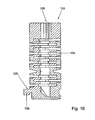
- Figs. 11-16 show a second exemplary embodiment of the invention.
- the second exemplary embodiment comprises a bicycle lock 101 whose housing 102 is provided with a holder part 102H and a blocking element in the form of a lock pin 128, connectable to or connected to the holder part 102H, and with a separate receiving part 102I which is provided with a lock pin opening for receiving a free end of the lock pin with the lock in the closed position.
- the holder part 102H and receiving part 102I can be connected to each other by means of, for instance, a bracket B or the like, but this is not required.
- the lock pin 128 can further, for instance, be pivotally connected to the holder part 102H, or detachably connectable to the holder part 102H.
- the lock pin 128 can for instance be slideable into the holder part 102H or the like.
- the thus designed bicycle lock 101 may be fitted onto a fork of a bicycle.
- the holder part 102H is for instance fitted adjacent one leg of the fork, while the lock pin 128 is pivotal between a releasing position, in which the lock pin 128 extends in a direction substantially parallel to said leg, and a blocking position in which the lock pin 128 extends between bicycle spokes, and is received by its free end in the receiving part 102I which, in use, is fitted adjacent another leg of the fork.
- the receiving part 102I is provided with a cylinder housing C' in which the lock pin opening and a lock cylinder are located, as well as a locking pawl 108 (see Fig. 12 ) to be locked and released with the aid of the lock cylinder 103, which locking pawl is designed for engaging a free end of the lock pin 128.
- the lock pin 128 can be provided at the free end with a recess in which the locking pawl 108 can engage for locking, and from which the locking pawl 108 can be moved through rotation of the lock cylinder 3 in the receiving part 102I for releasing the lock pin 128.
- Such a lock is known per se from practice.
- the lock cylinder 103 is provided (see Figs. 12 - 16 ) with a first cylinder part 104 with a cavity 109 extending from an outer end of this cylinder part 104 for receiving an operating key, and with a second cylinder part 106 coupled to the first cylinder part 104.
- the second cylinder part 106 is coupled by means of a first breakable joint 120 to an outer circumference of the first cylinder part 104.
- the breakable joint 120 comprises, for instance, a reduced portion, a weakening, a breaker groove, breakable material and/or the like.
- the second cylinder part 106 as such is the operating element 106 for operating the locking pawl 108 of the lock 101 during normal use of the lock. Therefore, the operating element 106 and said second cylinder part are one and the same part.
- the cavity 109 does not reach into the locking pawl operating element 106.
- the second exemplary embodiment is further provided with blocking means 111 which are designed for engaging the locking pawl operating element 106 such, at least after the cylinder 103 has been brought from the normal position of use to a forced position moved axially inwards relative to the lock housing 102, that the blocking means 111 check a rotation of the locking pawl operating element 106.
- the position of use is shown in Figs 12 - 13 and the forced cylinder position is represented in Figs. 14 - 15 .
- the blocking means of the second exemplary embodiment are provided with a blocking end plate 111, immovably coupled to the lock housing 102, with a blocking recess 112 for receiving the locking pawl operating element 106 after the cylinder 103 has been brought to the forced position.
- the blocking plate 111 can further serve for closing off one side of the receiving part 102I, for holding lock parts in the receiving part 102I.
- the second exemplary embodiment is further preferably provided with a second breakable joint, for instance a breaking edge or breaking ring 130, which couples the cylinder 103 to the lock housing 102 in a manner such that the cylinder 103 can be brought from the normal position of use to a position moved axially inwards relative to the lock housing 102, after breaking the second breakable joint.
- the second breakable joint breaks for instance when an object is struck from the outside into the cylinder 103.
- the locking pawl operating element 106 drops in the blocking recess 112 of the blocking plate 111, and the blocking plate 111 is blocked against rotation. If the cylinder 103 is then rotated with force, the locking pawl operating element 106 of the first cylinder part 104 will break off, through breaking of the breakable joint 120. Then, the cylinder 103 can rotate freely without being able to operate the locking pawl. Furthermore, the locking pawl operating element 106 is held against rotation by the blocking plate 111.
- the cylinder of the bicycle lock can be forced inwards, for instance under the influence of a force of impact. As a result, the cylinder can be brought in a locking position. When, thereupon, the cylinder is forced in a direction of rotation, a coupling with a lock operating part can be broken, so that operation of the lock has become impossible.
Abstract
Description
- The invention relates to a bicycle lock, comprising a lock housing and a lock cylinder, the lock cylinder being provided with:
- a first cylinder part with a key cavity extending from an outside end of this cylinder part for receiving an operating key, the key cavity being provided with locking plates operable by the key; and
- a second cylinder part coupled to the first cylinder part, which second cylinder part is provided with an operating element for operating at least one locking element of the lock during normal use of the lock; and the lock cylinder is provided with at least one breakable joint such that the second cylinder part can be uncoupled from the first cylinder part through breaking of this joint.
- Such a lock is known from
Dutch patent NL 1004151 - The object of the present invention is an improvement of a bicycle lock. In particular, the invention contemplates a bicycle lock which is particularly well protected against forcing, while preferably, operation of the lock can be prevented well after the lock cylinder has been forced with, for instance, an elongated tool.
- According to the invention, the bicycle lock is characterized in that the second cylinder part is not provided with the key cavity.
- During normal use, the cylinder can be rotated by means of a matching key. The first cylinder part is then rotated by means of the key. The breakable joint is preferably so strong that during normal use of the key, the first cylinder part carries the second cylinder part along in order that the operating element of the second cylinder part can effect a desired operation of the lock.
- During an attempt at forcing, the lock cylinder can for instance be forced by means of an elongated tool, wherein the tool is struck into the cavity of the first cylinder. However, this key cavity does not reach into the second cylinder part. That is why the tool cannot reach the second cylinder part. It is therefore not possible that with the tool, direct force is applied to the second cylinder part, which renders operating the locking element of the lock operating part by means of this tool particularly difficult, if not impossible.
- Under the influence of an attempt at forcing, the first breakable joint can for instance be broken so that the second cylinder part is no longer coupled in a manner fixed for rotation to the first cylinder part. In that case, the lock is protected well against unauthorized operation, since the operating element can hardly, if at all, be operated with tools from a surroundings.
- According to the invention, it is advantageous when the lock is provided with blocking means that are arranged to engage a part of the second cylinder part such, at least after the cylinder has been brought from a normal position of use to a forced position moved axially inwards relative to the lock housing, that the blocking means check a rotation of the second cylinder part.
- Under the influence of this checking by the blocking means, the first and second cylinder part can be uncoupled from each other in a simple manner, whereby a breaking of the first breakable joint occurs. Then, the second cylinder part is virtually inoperable for tools struck into the cylinder, so that operation of the lock is prevented.
- The invention further provides a bicycle according to claim 13, and a cylinder according to claim 14, which offers the above-mentioned advantages.
- Further elaborations of the invention are described in the subclaims. Presently, the invention will be clarified with reference to two exemplary embodiments and the drawing. In the drawing:
-
Fig. 1 shows a perspective front view of a first exemplary embodiment according to the invention; -
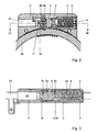
Fig. 2 shows a longitudinal cross-sectional view of a part of a first exemplary embodiment, in a condition of use; -
Fig. 3 shows a cross-sectional view along the line III-III ofFig. 2 ; -
Fig. 4A shows a side view of a part of the first exemplary embodiment; -
Fig. 4B shows a cross-sectional view along the line V-V ofFig. 4 , in the position of use; -
Fig. 5 shows a perspective, exploded view of a part of the exemplary embodiment represented inFig. 1 ; -
Fig. 6 shows detail Q ofFig. 5 in the position of use mentioned; -
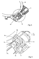
Fig. 7 shows a similar view toFig. 2 , in a forced position; -
Fig. 8 shows a cross-sectional view along the line VII-VII ofFig. 7 ; -
Fig. 9 shows a similar view toFig. 6 , in the forced position; -
Fig. 10 shows a front view of the cylinder of the first exemplary embodiment; -
Fig. 11 shows a perspective front view of a second exemplary embodiment of the invention; -
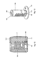
Fig. 12 shows a cross-sectional view of a lock part of the exemplary embodiment represented inFig. 11 , in a position of use; -
Fig. 13 shows a perspective drawing of a cylinder and end plate of the lock part represented inFig. 12 , in the position of use; -
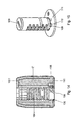
Fig. 14 shows a cross-sectional view of the lock part of the exemplary embodiment represented inFig. 11 , in a forced position; -
Fig. 15 shows a perspective drawing of a cylinder and end plate of the lock part represented inFig. 14 , in the forced position; and -
Fig. 16 shows a longitudinal cross-section of the cylinder of the second exemplary embodiment. - In the present application, identical or corresponding features are indicated with identical or corresponding reference numerals.
-
Figs. 1- 9 show a first exemplary embodiment of abicycle lock 1. The first exemplary embodiment is, in particular, aring lock 1. The ring lock is provided with alock housing 2 with anannular locking bolt 28. Thering lock 1 may additionally be provided with arecess 25 for receiving a cable pin of a loop-shaped antitheft cable (not shown). Thelock housing 2 comprises a cylinder housing C with acylinder 3. InFig. 1 , an arrow P indicates the insertion direction for inserting an operating key (not shown) into akey insertion cavity 9 of thelock cylinder 3. Theinsertion cavity 9 is provided with locking plates which are operable by the key. Through operation of thelock cylinder 3, at least through rotation thereof, alocking pawl 8a and acable pawl 8b can be operated for the purpose of locking/unlocking said locking bolt or cable pin, respectively. Such a ring lock is known per se from practice. - According to the present invention, the
lock cylinder 3 of the firstexemplary embodiment 1 is provided with (seeFigs. 3 and10 ): - a
first cylinder part 4 with acavity 9 extending from an outer end of thiscylinder part 4 for receiving an operating key; and - a
second cylinder part 6 coupled (fixed for rotation) to thefirst cylinder part 4, which second cylinder part is integrally provided withoperating elements locking pawl 8a andcable pawl 8b during normal use of the lock. Therefore, thekey cavity 9 only reaches into thefirst cylinder part 4 and not into thesecond cylinder part 6 and the second cylinder part is not provided with the locking plates mentioned. As a result, a forcing tool struck into thekey cavity 9 cannot engage the second cylinder part. - A normal position of use of the
lock 1 is represented inFigs. 1 - 6 . Thecylinder 3 of thelock 1 is provided with two operating elements, i.e a lockingpawl operating projection 7a for operating thelocking pawl 8a, and a cablepawl operating projection 7b extending axially to thelocking pawl projection 7b, for the purpose of operating thecable pawl 8b. Theoperating projections Fig. 10 ). - As shown in
Fig. 10 , thesecond cylinder part 6 is coupled to an inner end face of thefirst cylinder part 4 via a cylinderintermediate part 5. Theintermediate part 5 comprises a firstbreakable joint 20, so that thesecond cylinder part 6 can be uncoupled from thefirst cylinder part 4 through breaking of thisjoint 20. After breaking the first breakable joint 20, thefirst cylinder part 4 can be rotated independently of thesecond cylinder part 6. - The first breakable joint 20 can be designed in various manners, for instance as a reduced portion, a weakening, breaker groove, breakable material and/or the like. The first breakable joint 20 is especially designed to break when the cylinder
intermediate part 5 is subjected to a torque greater than torque normally experienced by thisintermediate part 5 during normal use of the lock. In addition, the first breakable joint 20 can break, for instance, under the influence of a pull-out force which is applied to thefirst cylinder part 4 for pulling thecylinder 3 from thelock housing 2. The cylinder housing C is provided with an arrestingflange 50 for arresting thesecond cylinder part 6 when thecylinder 3 is being pulled out. - As shown in
Figs. 1- 10 , thefirst cylinder part 4 can for instance also be provided with such a breakable joint 21 or breaking point in order that thefirst cylinder part 4 itself is breakable into two parts under the influence of an attempt at forcing. - The
lock 1 is further provided with blocking means 11 which are designed for engaging apart 7b of thesecond cylinder part 6 in such a manner, at least after thecylinder 3 has been brought from the normal position of use to a forced position moved axially inwards relative to thelock housing 2, that the blocking means 11 check a rotation of thesecond cylinder part 6. The forced position of thelock 1 is represented inFigs. 7 - 9 . In the exemplary embodiment, the first breakable joint 20 is breakable under the influence of rotation of thefirst cylinder part 4, at least when the cylinder is in the forced position while rotation of thesecond cylinder part 6 is checked by the blocking means 11. - As shown in
Figs. 2 - 9 , the blocking means in the first exemplary embodiment are provided with a blockingelement 11 immovably coupled to thelock housing 2. The blockingelement 11 may be an integral part of thelock housing 2, and in particular of the cylinder housing C.The blocking element 11 is provided with a blockingrecess 12 which is configured for engaging a blockingprojection 7b of thesecond cylinder part 6 after thesecond cylinder part 6 has been brought in a position moved towards the blockingelement 11. The blocking means can be designed in various other manners, and for instance comprise a blocking projection of the lock housing, which can engage a blocking recess of the second cylinder part, or in a different manner. - In the first exemplary embodiment, the cable
pawl operating projection 7b also serves as the blockingprojection 7b of thesecond cylinder part 6. As a result, thelock 1 can be designed to be, inter alia, relatively simple, compact and sturdy. - Further, in the normal position of use, the
cylinder 3 is coupled by means of at least one second breakable joint 30 to thelock housing 2 in a manner such that thecylinder 3 can be brought from this normal position of use to a position moved axially inwards relative to thelock housing 2, after breaking of the second breakable joint 30. The second breakable joint 30 is clearly visible inFig. 4B . This joint can comprise, for instance, adeformable projection 30 of thecylinder 3, whichprojection 30 engages thelock housing 2, or be designed in a different manner. - As shown in
Figs. 2 - 6 , with the lock in a normal position of use, the cablepawl operating projection 7b is located at a distance from the blockingrecess 12 of the blockingpart 11 of thelock housing 2. - When, during an attempt at forcing, a screwdriver or the like is struck with force into the
key cavity 9, in the direction of insertion P mentioned, the second breakable joint 30 is broken. As a result, thecylinder 3 slides to the forced position shown inFigs. 7-9 , and the cablepawl operating projection 7b of thesecond cylinder part 6 is slid into the blockingrecess 12. If, thereupon, a great torque is applied to thefirst cylinder part 4 via this screwdriver, the first breakable joint 20 breaks so that the first andsecond cylinder part second cylinder part 6 by means of the tool inserted into thekey insertion hole 9, whereby undesired operation of the lockingpawl 8a and thecable pawl 8b is prevented well. Secondly, the lockingpawl 8a andcable pawl 8b thus remain in a closed position, and are blocked by the blockingpart 11 of thelock housing 2, which offers additional safety against undesired opening of thelock 1. -
Figs. 11-16 show a second exemplary embodiment of the invention. The second exemplary embodiment comprises abicycle lock 101 whosehousing 102 is provided with a holder part 102H and a blocking element in the form of alock pin 128, connectable to or connected to the holder part 102H, and with a separate receiving part 102I which is provided with a lock pin opening for receiving a free end of the lock pin with the lock in the closed position. The holder part 102H and receiving part 102I can be connected to each other by means of, for instance, a bracket B or the like, but this is not required. Thelock pin 128 can further, for instance, be pivotally connected to the holder part 102H, or detachably connectable to the holder part 102H. Thelock pin 128 can for instance be slideable into the holder part 102H or the like. The thus designedbicycle lock 101 may be fitted onto a fork of a bicycle. In use, the holder part 102H is for instance fitted adjacent one leg of the fork, while thelock pin 128 is pivotal between a releasing position, in which thelock pin 128 extends in a direction substantially parallel to said leg, and a blocking position in which thelock pin 128 extends between bicycle spokes, and is received by its free end in the receiving part 102I which, in use, is fitted adjacent another leg of the fork. - The receiving part 102I is provided with a cylinder housing C' in which the lock pin opening and a lock cylinder are located, as well as a locking pawl 108 (see
Fig. 12 ) to be locked and released with the aid of thelock cylinder 103, which locking pawl is designed for engaging a free end of thelock pin 128. To that end, thelock pin 128 can be provided at the free end with a recess in which the lockingpawl 108 can engage for locking, and from which the lockingpawl 108 can be moved through rotation of thelock cylinder 3 in the receiving part 102I for releasing thelock pin 128. Such a lock is known per se from practice. - With the second
exemplary embodiment 101, thelock cylinder 103 is provided (seeFigs. 12 - 16 ) with afirst cylinder part 104 with acavity 109 extending from an outer end of thiscylinder part 104 for receiving an operating key, and with asecond cylinder part 106 coupled to thefirst cylinder part 104. Thesecond cylinder part 106 is coupled by means of a first breakable joint 120 to an outer circumference of thefirst cylinder part 104. The breakable joint 120 comprises, for instance, a reduced portion, a weakening, a breaker groove, breakable material and/or the like. - With the second exemplary embodiment, the
second cylinder part 106 as such is theoperating element 106 for operating the lockingpawl 108 of thelock 101 during normal use of the lock. Therefore, theoperating element 106 and said second cylinder part are one and the same part. Thecavity 109 does not reach into the lockingpawl operating element 106. The second exemplary embodiment is further provided with blocking means 111 which are designed for engaging the lockingpawl operating element 106 such, at least after thecylinder 103 has been brought from the normal position of use to a forced position moved axially inwards relative to thelock housing 102, that the blocking means 111 check a rotation of the lockingpawl operating element 106. The position of use is shown inFigs 12 - 13 and the forced cylinder position is represented inFigs. 14 - 15 . - The blocking means of the second exemplary embodiment are provided with a blocking
end plate 111, immovably coupled to thelock housing 102, with a blockingrecess 112 for receiving the lockingpawl operating element 106 after thecylinder 103 has been brought to the forced position. The blockingplate 111 can further serve for closing off one side of the receiving part 102I, for holding lock parts in the receiving part 102I. The second exemplary embodiment is further preferably provided with a second breakable joint, for instance a breaking edge or breakingring 130, which couples thecylinder 103 to thelock housing 102 in a manner such that thecylinder 103 can be brought from the normal position of use to a position moved axially inwards relative to thelock housing 102, after breaking the second breakable joint. The second breakable joint breaks for instance when an object is struck from the outside into thecylinder 103. - When the
cylinder 103 of the second exemplary embodiment has been forced to a position shown inFigs. 14 and 15 , for instance after breaking said breaking edge or breakingring 130, the lockingpawl operating element 106 drops in theblocking recess 112 of the blockingplate 111, and the blockingplate 111 is blocked against rotation. If thecylinder 103 is then rotated with force, the lockingpawl operating element 106 of thefirst cylinder part 104 will break off, through breaking of thebreakable joint 120. Then, thecylinder 103 can rotate freely without being able to operate the locking pawl. Furthermore, the lockingpawl operating element 106 is held against rotation by the blockingplate 111. - In this manner, the
lock 102 is particularly well protected against an attempt at forcing. - According to the invention, in view of the above, for instance first, the cylinder of the bicycle lock can be forced inwards, for instance under the influence of a force of impact. As a result, the cylinder can be brought in a locking position. When, thereupon, the cylinder is forced in a direction of rotation, a coupling with a lock operating part can be broken, so that operation of the lock has become impossible.
- It is self evident that the invention is not limited to the exemplary embodiments described. Various modifications are possible within the framework of the invention as set forth in the following claims.
Claims (14)
- A bicycle lock, comprising a lock housing (2; 102) and a lock cylinder (3; 103), wherein the lock cylinder (3; 103) is provided with:- a first cylinder part (4; 104) with a key cavity (9; 106) extending from an outside end of this cylinder part for receiving an operating key, the key cavity (9; 109) being provided with locking plates operable by the key; and- a second cylinder part (6; 106) coupled to the first cylinder part (4; 104), which second cylinder part is provided with at least one operating element (7a, 7b; 106) for operating at least one locking element (8a, 8b; 108) of the lock (1; 101) during normal use of the lock; the cylinder (3; 103) is provided with at least one first breakable joint (20; 120) such that the second cylinder part (6; 106) can be uncoupled from the first cylinder part (4; 104) through breaking of this joint (20; 120) ;characterized in that the second cylinder part (6; 106) is not provided with said key cavity (9; 109).
- A bicycle lock according-to claim 1, wherein the lock is provided with blocking means (11; 111) which are designed for engaging a part (7b; 106) of said second cylinder part (6; 106) such, at least after the cylinder (3; 103) has been brought from a normal position of use to a forced position moved axially inwards relative to the lock housing (2; 102), that the blocking means (11; 111) check a rotation of the second cylinder part (6; 106).
- A bicycle lock according to claim 2, wherein said blocking means are provided with a blocking element (11; 111) immovably coupled to the lock housing (2; 102), the blocking element (11; 111) being provided with a blocking recess (12; 112) or a blocking projection for engaging a blocking projection (7b; 106) or a blocking recess, respectively, of said second cylinder part (6; 106) after the second cylinder part (6; 106) has been brought to a position moved towards the blocking element (11; 111).
- A bicycle lock according to claim 3, wherein a said operating element (7b; 106) on the one side and said blocking projection (7b) of the second cylinder part (6; 106) on the other side are one and the same part.
- A bicycle lock according to any one of claims 2 - 4, wherein the said first breakable joint is breakable under the influence of rotation of the first cylinder part, at least when rotation of the second cylinder part is checked by the blocking means (11; 111).
- A bicycle lock according to any one of the preceding claims, wherein the second cylinder part (6) is coupled to an inner end face of the first cylinder part (4), via a cylinder intermediate part (5), with said key cavity (9) not reaching into this intermediate part (5), while the cylinder intermediate part (5) is provided with a breaking part (20).
- A bicycle lock according to claim 6, wherein said operating element (7a, 7b) is formed by at least one operating projection extending on the second cylinder part (6) for instance on an end face of this cylinder part (6).
- A bicycle lock according to any one of claims 1- 5, wherein said operating element (106) and said second cylinder part are one and the same part.
- A bicycle lock according to claim 8, wherein the second cylinder part (106) is coupled by means of said first breakable joint (120) to an outer circumference of the first cylinder part (104).
- A bicycle lock according to any one of the preceding claims, wherein said first breakable joint (20; 120) comprises a reduced portion, a breaker groove, breakable material and/or a weakening of a respective lock part.
- A bicycle lock according to any one of the preceding claims, wherein said cylinder (3; 103), in a normal position of use, is coupled by means of at least one second breakable joint (30; 130) to the lock housing (2; 102) such that the cylinder (3; 103) can be brought from this normal position of use to a position moved axially inwards relative to the lock housing (2; 102) after breaking of the second breakable joint (30; 130).
- A bicycle lock according to any one of the preceding claims, comprising:- a ring lock which is provided with a lock housing with an annular locking bolt; or- a lock whose housing is provided with a holder part and with a blocking element in the form of a lock pin connectable to or connected to the holder part, and with a receiving part which is provided with a lock pin opening for receiving a free end of the lock pin with the lock in a closed position.
- A bicycle provided with a lock according to any one of the preceding claims.
- A cylinder of a lock according to any one of claims 1-12.
Applications Claiming Priority (1)
| Application Number | Priority Date | Filing Date | Title |
|---|---|---|---|
| NL1028885A NL1028885C2 (en) | 2005-04-27 | 2005-04-27 | Bicycle lock. |
Publications (2)
| Publication Number | Publication Date |
|---|---|
| EP1717135A1 EP1717135A1 (en) | 2006-11-02 |
| EP1717135B1 true EP1717135B1 (en) | 2009-02-11 |
Family
ID=35447294
Family Applications (1)
| Application Number | Title | Priority Date | Filing Date |
|---|---|---|---|
| EP06075902A Active EP1717135B1 (en) | 2005-04-27 | 2006-04-18 | Bicycle lock |
Country Status (5)
| Country | Link |
|---|---|
| EP (1) | EP1717135B1 (en) |
| AT (1) | ATE422460T1 (en) |
| DE (1) | DE602006005093D1 (en) |
| DK (1) | DK1717135T3 (en) |
| NL (1) | NL1028885C2 (en) |
Families Citing this family (6)
| Publication number | Priority date | Publication date | Assignee | Title |
|---|---|---|---|---|
| CN102086725B (en) * | 2009-12-05 | 2013-01-02 | 昆山通用锁具有限公司 | Horseshoe lock head |
| DE102010008054B4 (en) * | 2010-02-16 | 2023-01-12 | ABUS August Bremicker Söhne Kommanditgesellschaft | Bicycle lock |
| NL2013132B1 (en) | 2014-07-04 | 2016-08-16 | Axa Stenman Nederland B V | Ring-clip lock with detachable chain or cable. |
| NL2013131B1 (en) | 2014-07-04 | 2016-09-09 | Axa Stenman Nederland B V | Ring-bar lock and a method for assembling such a ring-bar lock. |
| DE102015103170A1 (en) * | 2015-03-04 | 2016-09-08 | ABUS August Bremicker Söhne KG | frame lock |
| TWI738559B (en) * | 2020-11-09 | 2021-09-01 | 美商糖果屋研發有限公司 | Lock |
Family Cites Families (5)
| Publication number | Priority date | Publication date | Assignee | Title |
|---|---|---|---|---|
| DE2557063A1 (en) * | 1975-12-18 | 1977-06-30 | Stucke Lothar | Profiled double cylinder lock for doors - has fracturing position in web for protecting holding screw in lock during forced entry attempt |
| NL9500355A (en) * | 1995-02-23 | 1996-10-01 | Stenman Holland Nv | Bicycle lock of the ring bracket type. |
| NL1004151C2 (en) | 1996-09-30 | 1997-08-19 | Stenman Holland Nv | Stirrup-type bicycle lock - has rear end of lock cylinder clear of, and coupled to, locking plate working which works with locking stirrup |
| GB2318824B (en) * | 1996-11-02 | 2001-01-31 | Anglian Windows Ltd | Euro-cylinder door locks |
| CN100564780C (en) * | 2002-12-19 | 2009-12-02 | 胡夫休尔斯贝克及福尔斯特公司 | The operating means that is used for the lock of arrangements for automotive doors or car bonnet |
-
2005
- 2005-04-27 NL NL1028885A patent/NL1028885C2/en active Search and Examination
-
2006
- 2006-04-18 EP EP06075902A patent/EP1717135B1/en active Active
- 2006-04-18 DE DE602006005093T patent/DE602006005093D1/en active Active
- 2006-04-18 DK DK06075902T patent/DK1717135T3/en active
- 2006-04-18 AT AT06075902T patent/ATE422460T1/en not_active IP Right Cessation
Also Published As
| Publication number | Publication date |
|---|---|
| EP1717135A1 (en) | 2006-11-02 |
| DK1717135T3 (en) | 2009-06-02 |
| ATE422460T1 (en) | 2009-02-15 |
| NL1028885C2 (en) | 2006-10-30 |
| DE602006005093D1 (en) | 2009-03-26 |
Similar Documents
| Publication | Publication Date | Title |
|---|---|---|
| EP1717135B1 (en) | Bicycle lock | |
| EP2494129B1 (en) | Lock mechanism | |
| RU2528156C2 (en) | Lock mechanism | |
| KR101124976B1 (en) | Coupling mechanism for door lock cover of vehicle | |
| EP2529069A1 (en) | Door cylinder lock | |
| JP4927023B2 (en) | Emergency stop pushbutton switch | |
| GB2549193A (en) | A lock | |
| EP1925764B1 (en) | Handle for vehicle doors, handle and tool as well as processes for assembling or disassembling this handle | |
| CN105936307A (en) | Frame lock | |
| US7469920B2 (en) | Kingpin lock | |
| EP1277900B1 (en) | Vehicle door handle | |
| CA2639167A1 (en) | Cylinder lock assembly with a tailpiece rotationally coupled to the cylinder plug | |
| CN1626762B (en) | Frame lock with pivotable shackle and locking system for a bicycle | |
| GB2372535A (en) | Security double profile cylinder lock | |
| US6962066B2 (en) | Locking arrangement for a door | |
| EP1707710B1 (en) | Non-destructible cylinder lock | |
| WO2008072974A1 (en) | Door handle | |
| KR100707125B1 (en) | Enhanced security catch assembly for retaining a handle on a spindle | |
| US7334439B2 (en) | Accessory lock assembly | |
| ITPN20150003U1 (en) | PROTECTION ASSEMBLY FOR EUROPEAN CYLINDER LOCKS | |
| CN211422134U (en) | Anti-prying double-opening safety lock | |
| AU785407B2 (en) | Improvements in locks | |
| JP2006207211A (en) | Cylinder lock | |
| EP3006651B1 (en) | Cylinder lock | |
| EP1614612B1 (en) | Lock intended to be mounted on the fork of a bicycle, moped or like two-wheeler |
Legal Events
| Date | Code | Title | Description |
|---|---|---|---|
| PUAI | Public reference made under article 153(3) epc to a published international application that has entered the european phase |
Free format text: ORIGINAL CODE: 0009012 |
|
| AK | Designated contracting states |
Kind code of ref document: A1 Designated state(s): AT BE BG CH CY CZ DE DK EE ES FI FR GB GR HU IE IS IT LI LT LU LV MC NL PL PT RO SE SI SK TR |
|
| AX | Request for extension of the european patent |
Extension state: AL BA HR MK YU |
|
| 17P | Request for examination filed |
Effective date: 20070405 |
|
| 17Q | First examination report despatched |
Effective date: 20070524 |
|
| AKX | Designation fees paid |
Designated state(s): AT BE BG CH CY CZ DE DK EE ES FI FR GB GR HU IE IS IT LI LT LU LV MC NL PL PT RO SE SI SK TR |
|
| GRAP | Despatch of communication of intention to grant a patent |
Free format text: ORIGINAL CODE: EPIDOSNIGR1 |
|
| GRAS | Grant fee paid |
Free format text: ORIGINAL CODE: EPIDOSNIGR3 |
|
| GRAA | (expected) grant |
Free format text: ORIGINAL CODE: 0009210 |
|
| AK | Designated contracting states |
Kind code of ref document: B1 Designated state(s): AT BE BG CH CY CZ DE DK EE ES FI FR GB GR HU IE IS IT LI LT LU LV MC NL PL PT RO SE SI SK TR |
|
| REG | Reference to a national code |
Ref country code: GB Ref legal event code: FG4D |
|
| REG | Reference to a national code |
Ref country code: CH Ref legal event code: EP |
|
| REG | Reference to a national code |
Ref country code: IE Ref legal event code: FG4D |
|
| REF | Corresponds to: |
Ref document number: 602006005093 Country of ref document: DE Date of ref document: 20090326 Kind code of ref document: P |
|
| REG | Reference to a national code |
Ref country code: DK Ref legal event code: T3 |
|
| PG25 | Lapsed in a contracting state [announced via postgrant information from national office to epo] |
Ref country code: SI Free format text: LAPSE BECAUSE OF FAILURE TO SUBMIT A TRANSLATION OF THE DESCRIPTION OR TO PAY THE FEE WITHIN THE PRESCRIBED TIME-LIMIT Effective date: 20090211 Ref country code: NL Free format text: LAPSE BECAUSE OF FAILURE TO SUBMIT A TRANSLATION OF THE DESCRIPTION OR TO PAY THE FEE WITHIN THE PRESCRIBED TIME-LIMIT Effective date: 20090211 Ref country code: FI Free format text: LAPSE BECAUSE OF FAILURE TO SUBMIT A TRANSLATION OF THE DESCRIPTION OR TO PAY THE FEE WITHIN THE PRESCRIBED TIME-LIMIT Effective date: 20090211 Ref country code: ES Free format text: LAPSE BECAUSE OF FAILURE TO SUBMIT A TRANSLATION OF THE DESCRIPTION OR TO PAY THE FEE WITHIN THE PRESCRIBED TIME-LIMIT Effective date: 20090522 Ref country code: LT Free format text: LAPSE BECAUSE OF FAILURE TO SUBMIT A TRANSLATION OF THE DESCRIPTION OR TO PAY THE FEE WITHIN THE PRESCRIBED TIME-LIMIT Effective date: 20090211 |
|
| NLV1 | Nl: lapsed or annulled due to failure to fulfill the requirements of art. 29p and 29m of the patents act | ||
| PG25 | Lapsed in a contracting state [announced via postgrant information from national office to epo] |
Ref country code: SE Free format text: LAPSE BECAUSE OF FAILURE TO SUBMIT A TRANSLATION OF THE DESCRIPTION OR TO PAY THE FEE WITHIN THE PRESCRIBED TIME-LIMIT Effective date: 20090511 Ref country code: LV Free format text: LAPSE BECAUSE OF FAILURE TO SUBMIT A TRANSLATION OF THE DESCRIPTION OR TO PAY THE FEE WITHIN THE PRESCRIBED TIME-LIMIT Effective date: 20090211 Ref country code: AT Free format text: LAPSE BECAUSE OF FAILURE TO SUBMIT A TRANSLATION OF THE DESCRIPTION OR TO PAY THE FEE WITHIN THE PRESCRIBED TIME-LIMIT Effective date: 20090211 Ref country code: IS Free format text: LAPSE BECAUSE OF FAILURE TO SUBMIT A TRANSLATION OF THE DESCRIPTION OR TO PAY THE FEE WITHIN THE PRESCRIBED TIME-LIMIT Effective date: 20090611 Ref country code: PL Free format text: LAPSE BECAUSE OF FAILURE TO SUBMIT A TRANSLATION OF THE DESCRIPTION OR TO PAY THE FEE WITHIN THE PRESCRIBED TIME-LIMIT Effective date: 20090211 |
|
| PG25 | Lapsed in a contracting state [announced via postgrant information from national office to epo] |
Ref country code: BE Free format text: LAPSE BECAUSE OF FAILURE TO SUBMIT A TRANSLATION OF THE DESCRIPTION OR TO PAY THE FEE WITHIN THE PRESCRIBED TIME-LIMIT Effective date: 20090211 |
|
| PG25 | Lapsed in a contracting state [announced via postgrant information from national office to epo] |
Ref country code: EE Free format text: LAPSE BECAUSE OF FAILURE TO SUBMIT A TRANSLATION OF THE DESCRIPTION OR TO PAY THE FEE WITHIN THE PRESCRIBED TIME-LIMIT Effective date: 20090211 Ref country code: PT Free format text: LAPSE BECAUSE OF FAILURE TO SUBMIT A TRANSLATION OF THE DESCRIPTION OR TO PAY THE FEE WITHIN THE PRESCRIBED TIME-LIMIT Effective date: 20090713 Ref country code: CZ Free format text: LAPSE BECAUSE OF FAILURE TO SUBMIT A TRANSLATION OF THE DESCRIPTION OR TO PAY THE FEE WITHIN THE PRESCRIBED TIME-LIMIT Effective date: 20090211 |
|
| PG25 | Lapsed in a contracting state [announced via postgrant information from national office to epo] |
Ref country code: SK Free format text: LAPSE BECAUSE OF FAILURE TO SUBMIT A TRANSLATION OF THE DESCRIPTION OR TO PAY THE FEE WITHIN THE PRESCRIBED TIME-LIMIT Effective date: 20090211 Ref country code: RO Free format text: LAPSE BECAUSE OF FAILURE TO SUBMIT A TRANSLATION OF THE DESCRIPTION OR TO PAY THE FEE WITHIN THE PRESCRIBED TIME-LIMIT Effective date: 20090211 |
|
| PLBE | No opposition filed within time limit |
Free format text: ORIGINAL CODE: 0009261 |
|
| STAA | Information on the status of an ep patent application or granted ep patent |
Free format text: STATUS: NO OPPOSITION FILED WITHIN TIME LIMIT |
|
| 26N | No opposition filed |
Effective date: 20091112 |
|
| REG | Reference to a national code |
Ref country code: FR Ref legal event code: ST Effective date: 20091231 |
|
| PG25 | Lapsed in a contracting state [announced via postgrant information from national office to epo] |
Ref country code: BG Free format text: LAPSE BECAUSE OF FAILURE TO SUBMIT A TRANSLATION OF THE DESCRIPTION OR TO PAY THE FEE WITHIN THE PRESCRIBED TIME-LIMIT Effective date: 20090511 |
|
| REG | Reference to a national code |
Ref country code: IE Ref legal event code: MM4A |
|
| PG25 | Lapsed in a contracting state [announced via postgrant information from national office to epo] |
Ref country code: FR Free format text: LAPSE BECAUSE OF NON-PAYMENT OF DUE FEES Effective date: 20091222 Ref country code: MC Free format text: LAPSE BECAUSE OF NON-PAYMENT OF DUE FEES Effective date: 20090430 Ref country code: IE Free format text: LAPSE BECAUSE OF NON-PAYMENT OF DUE FEES Effective date: 20090418 |
|
| PG25 | Lapsed in a contracting state [announced via postgrant information from national office to epo] |
Ref country code: GR Free format text: LAPSE BECAUSE OF FAILURE TO SUBMIT A TRANSLATION OF THE DESCRIPTION OR TO PAY THE FEE WITHIN THE PRESCRIBED TIME-LIMIT Effective date: 20090512 |
|
| REG | Reference to a national code |
Ref country code: CH Ref legal event code: PL |
|
| GBPC | Gb: european patent ceased through non-payment of renewal fee |
Effective date: 20100418 |
|
| PG25 | Lapsed in a contracting state [announced via postgrant information from national office to epo] |
Ref country code: LI Free format text: LAPSE BECAUSE OF NON-PAYMENT OF DUE FEES Effective date: 20100430 Ref country code: CH Free format text: LAPSE BECAUSE OF NON-PAYMENT OF DUE FEES Effective date: 20100430 |
|
| PG25 | Lapsed in a contracting state [announced via postgrant information from national office to epo] |
Ref country code: IT Free format text: LAPSE BECAUSE OF FAILURE TO SUBMIT A TRANSLATION OF THE DESCRIPTION OR TO PAY THE FEE WITHIN THE PRESCRIBED TIME-LIMIT Effective date: 20090211 Ref country code: GB Free format text: LAPSE BECAUSE OF NON-PAYMENT OF DUE FEES Effective date: 20100418 |
|
| PG25 | Lapsed in a contracting state [announced via postgrant information from national office to epo] |
Ref country code: LU Free format text: LAPSE BECAUSE OF NON-PAYMENT OF DUE FEES Effective date: 20090418 |
|
| PG25 | Lapsed in a contracting state [announced via postgrant information from national office to epo] |
Ref country code: HU Free format text: LAPSE BECAUSE OF FAILURE TO SUBMIT A TRANSLATION OF THE DESCRIPTION OR TO PAY THE FEE WITHIN THE PRESCRIBED TIME-LIMIT Effective date: 20090812 |
|
| PG25 | Lapsed in a contracting state [announced via postgrant information from national office to epo] |
Ref country code: TR Free format text: LAPSE BECAUSE OF FAILURE TO SUBMIT A TRANSLATION OF THE DESCRIPTION OR TO PAY THE FEE WITHIN THE PRESCRIBED TIME-LIMIT Effective date: 20090211 |
|
| PG25 | Lapsed in a contracting state [announced via postgrant information from national office to epo] |
Ref country code: CY Free format text: LAPSE BECAUSE OF FAILURE TO SUBMIT A TRANSLATION OF THE DESCRIPTION OR TO PAY THE FEE WITHIN THE PRESCRIBED TIME-LIMIT Effective date: 20090211 |
|
| REG | Reference to a national code |
Ref country code: DE Ref legal event code: R082 Ref document number: 602006005093 Country of ref document: DE Representative=s name: VEREENIGDE OCTROOIBUREAUX V.O., DE |
|
| REG | Reference to a national code |
Ref country code: DE Ref legal event code: R081 Ref document number: 602006005093 Country of ref document: DE Owner name: AXA STENMAN NEDERLAND B.V., NL Free format text: FORMER OWNER: STENMAN HOLLAND B.V., VEENENDAAL, NL |
|
| REG | Reference to a national code |
Ref country code: DE Ref legal event code: R082 Ref document number: 602006005093 Country of ref document: DE Representative=s name: VEREENIGDE OCTROOIBUREAUX V.O., DE Ref country code: DE Ref legal event code: R081 Ref document number: 602006005093 Country of ref document: DE Owner name: ALLEGION NETHERLANDS B.V., NL Free format text: FORMER OWNER: AXA STENMAN NEDERLAND B.V., VEENENDAAL, NL |
|
| PGFP | Annual fee paid to national office [announced via postgrant information from national office to epo] |
Ref country code: DK Payment date: 20230421 Year of fee payment: 18 Ref country code: DE Payment date: 20230420 Year of fee payment: 18 |