EP1717064A1 - Werkzeug für die Montage / Demontage von Fahrzeugreifen - Google Patents
Werkzeug für die Montage / Demontage von Fahrzeugreifen Download PDFInfo
- Publication number
- EP1717064A1 EP1717064A1 EP06008888A EP06008888A EP1717064A1 EP 1717064 A1 EP1717064 A1 EP 1717064A1 EP 06008888 A EP06008888 A EP 06008888A EP 06008888 A EP06008888 A EP 06008888A EP 1717064 A1 EP1717064 A1 EP 1717064A1
- Authority
- EP
- European Patent Office
- Prior art keywords
- tool according
- attachment body
- rotation
- bead
- rotation axis
- Prior art date
- Legal status (The legal status is an assumption and is not a legal conclusion. Google has not performed a legal analysis and makes no representation as to the accuracy of the status listed.)
- Granted
Links
Images


Classifications
-
- B—PERFORMING OPERATIONS; TRANSPORTING
- B60—VEHICLES IN GENERAL
- B60C—VEHICLE TYRES; TYRE INFLATION; TYRE CHANGING; CONNECTING VALVES TO INFLATABLE ELASTIC BODIES IN GENERAL; DEVICES OR ARRANGEMENTS RELATED TO TYRES
- B60C25/00—Apparatus or tools adapted for mounting, removing or inspecting tyres
- B60C25/01—Apparatus or tools adapted for mounting, removing or inspecting tyres for removing tyres from or mounting tyres on wheels
- B60C25/05—Machines
- B60C25/132—Machines for removing and mounting tyres
- B60C25/135—Machines for removing and mounting tyres having a tyre support or a tool, movable along wheel axis
- B60C25/138—Machines for removing and mounting tyres having a tyre support or a tool, movable along wheel axis with rotary motion of tool or tyre support
Definitions
- the present invention refers to a tool for fitting and removing vehicle wheel tyres.
- vehicle wheels generally consist of a cylindrical metal rim featuring, at the axial ends, annular folds between which a slot-in fitting channel is defined for an elastic tyre, the side sections of which, the so-called “beads”, are tightly fitted up against the annular folds.
- an inner tube Inside the tyre, an inner tube can be fitted or, in the case of "tubeless" type tyres, air under pressure can be directly introduced.
- tyre-changing machines that make it possible to remove the tyre from the relevant rim to carry out, for example, maintenance jobs or to replace the inner tube, the rim and/or the tyre itself, and then fit the same tyre or a replacement tyre back on the wheel rim.
- a particular type of tyre-changing machine is essentially made up of a support frame for means of gripping and rotating the rim of a wheel being worked on, and for a tool arm on which is fitted a tool for fitting and removing the tyre onto and off the rim.
- Such tool is fitted between the tyre beads and the corresponding annular folds of the rim to detach these, during removal, and to press on the beads inside the channel defined between the annular folds, during fitting.
- the tool features a pair of bead pressers combined integrally in a single rigid body, made of metal or plastic.
- One of these bead pressers is normally shaped like a tang, meaning it is extended in an orthogonal direction to the rotation axis of the rim and features a substantially sharp end.
- the other bead presser on the other hand can be shaped like a roller or, alternatively, like an extended wing in an orthogonal direction to the rotation axis of the rim different to that of the tang.
- the angle and the relevant distance between the tang and the roller, or between the tang and the wing, are set during manufacture.
- the bead pressing part shaped like a tang may have an end placed awkwardly distant from the annular fold of the rim and, consequently, it could cause excessive deformation of the tyre with which it is in contact, with the risk of ruining it.
- the thrust action of the tool can involve too large, or too small a surface of the tyre bead.
- the aim of the present invention is to eliminate the problems complained of above associated with the known technology and devise a tool for fitting and removing vehicle wheel tyres of universal use and suitable whatever the size of the wheel rim.
- another purpose of the present invention is to achieve the previous aims with a simple structure, of relatively practical implementation, safe use and effective operation, as well as of a relatively low cost.
- this tool for fitting and removing vehicle wheel tyres comprising at least one attachment body to the tool arm of a tyre-changing machine featuring means of gripping and rotating the rim of a wheel around a rotation axis, and at least a first and a second bead presser part, said first part being extended in a substantially orthogonal direction to said rotation axis, that can be associated with said attachment body and able to cooperate together to deform the bead of a tyre to be fitted/removed on/from said rim, characterized in that said first bead presser part can be associated with said attachment body by interposing means of rotation around a swinging axis substantially parallel to said rotation axis, able to allow the positioning of said first part in a work configuration in which this is substantially tangent to one of the annular folds of said rim.
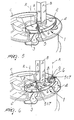
- a tool for fitting and removing vehicle wheel tyres has been generally designated by reference numeral 1.
- the tool 1 is suitable for being fitted on a tyre-changing machine M equipped with a tool arm B and means of gripping and rotating rim C of a vehicle wheel; such means, in particular, are of the spindle Mn type with rotation axis R substantially vertical, although alternative forms of embodiment of the present invention cannot be ruled out in which such axis is horizontal or otherwise tilted.
- the tool 1 comprises an attachment body 2 to arm B of the tyre-changing machine M, a first bead presser part 3 and a second bead presser part 4, that can be associated with the attachment body 2 and able to cooperate together to deform the bead of a tyre to be fitted/removed to/from the rim C.
- the attachment body 2 consists of a slab which, in operating position, is kept substantially orthogonal to the rotation axis R.
- the shape and dimensions of the first and second bead presser parts 3 and 4 can be different.
- the first bead presser part 3 anyway, extends in an orthogonal direction to the rotation axis R and can be associated with the attachment body 2 by interposing the means of rotation 5, of the cylindrical hinge type, around a swinging axis A parallel to the rotation axis R, able to allow the positioning of the part itself in a work configuration in which this is substantially tangent to one of the annular folds of rim C.
- the first bead presser part 3 for example, can be shaped like a tang featuring a sharp tip able to be fitted between the rim C and the base of the tyre bead (figures 2, 3 and 5), or can be shaped like a wing (figure 4); in any case it is fitted on the attachment body 2 so as to turn around the swinging axis A.
- the second bead presser part 4 can also be extended in an orthogonal direction to the rotation axis R and eventually be associated with the slab 2 through the means of rotation 5.
- the second bead presser part 4 for example, can be shaped like a wing that can turn with respect to the slab 2 (figure 2), with wing integral with the slab 2 (figure 3), or with tang integral with the attachment body 2 (figure 4).
- the second bead presser part 4 is shaped like a roller hinged to the slab 2 and able to roll against the tyre during the rotation operation of rim C.
- the tool 1 features temporary means of fastening 6 of the first bead presser part 3 and eventually of the second bead presser part 4, in work configuration; these means of fastening, for example, consist of one or more retention nuts or similar.
- first bead presser part 3 and eventually the second bead presser part 4 be left free to turn around the swinging axes A, the positioning in work configuration being provided by the crushing of the tyre on rim C during operation.
- the bead presser parts 3 and 4 are associated with the slab 2 through means of adjustment 7 of their relevant distance on the orthogonal surface to the rotation axis R.
- Such means of adjustment can have different embodiments; in figure 6, for example, these consist of a plurality of holes 8 obtained in the slab 2 at preset relevant distances, inside which a connecting pin 9 can be fitted and secured in a removable way associated with each bead presser part 3 and 4.
- the coupling between the holes 8 and the connecting pins 9 is substantially cylindrical, so that the bead presser parts 3 and 4 can turn inside them; in this case the means of rotation 5 and the means of adjustment 7 coincide together.
- the second bead presser part 4 is made integral with the slab 2, the adjustment of the relevant distance between the bead presser parts 3 and 4 being provided by the moving of the first bead presser part 3 only.
- the means of adjustment 7 comprise two plates 10 associated with the attachment body 2 in a way such as to turn around an axis parallel with the rotation axis R and each supporting one of the bead presser parts 3 and 4, so that the rotation of the plates 10 with respect to the attachment body 2 permits moving the bead presser parts 3 and 4 away/closer to one another.
- the means of rotation 5 are placed between the first bead presser part 3, shaped like a tang, and the relevant plate 10, so as to allow its positioning in work configuration, while the second bead presser part 4 is shaped like a roller.
- first and second bead presser parts 3 and 4 have different shapes and dimensions consistently with what has been said before.
- the means of adjustment 7 of figure 7 feature first removable means of retention 11 of the rotation of the plates 10 which, for example, comprise a plurality of first through eyelets 12 obtained in the slab 2 and a second through eyelet, not shown in detail in figure 7, obtained in each plate 10.
- Such first removable means of retention also include a retention pin 13 for each plate 10, which can be fitted in the corresponding second eyelet and, alternatively, in one of the first eyelets 12 arranged coinciding with the second eyelet.
- the means of adjustment 7 comprise two gear wheels 14 locked together and fitted on the slab 2 so as to rotate around axes parallel to the rotation axis R.
- the gear wheels 14 each support one of the bead presser parts 3 and 4 and their rotation makes it possible to move one bead presser part 3 and 4 away from/closer to the other.
- second removable means of retention 15 of the rotation of gear wheels 14 are envisaged which, advantageously, consist of a toothed spool that can be fitted on the attachment body 2 in a retention configuration in which this is simultaneously engaged with the teeth of the gear wheels 14, so as to prevent their rotation.
- the means of rotation 5 are placed between the first bead presser part 3, shaped like a tang, and the relevant gear wheel 14, while the second bead presser part 4 is shaped like a roller.
- first and second bead presser parts 3 and 4 have different shapes and dimensions consistently with what has been said before.
- the means of adjustment 7 are of the telescopic type and feature two or more tubular sections orthogonal to the rotation axis R which support the bead presser parts 3 and 4 and are fitted so as to slide the one inside the other so as to move the parts away/closer to one another at will.
Landscapes
- Engineering & Computer Science (AREA)
- Mechanical Engineering (AREA)
- Tires In General (AREA)
- Automatic Assembly (AREA)
- Fittings On The Vehicle Exterior For Carrying Loads, And Devices For Holding Or Mounting Articles (AREA)
- Processing And Handling Of Plastics And Other Materials For Molding In General (AREA)
- Automobile Manufacture Line, Endless Track Vehicle, Trailer (AREA)
- Processing Of Solid Wastes (AREA)
Applications Claiming Priority (1)
| Application Number | Priority Date | Filing Date | Title |
|---|---|---|---|
| IT000105A ITMO20050105A1 (it) | 2005-04-29 | 2005-04-29 | Utensile per il montaggio e lo smontaggio di pneumatici di ruote per veicoli. |
Publications (2)
| Publication Number | Publication Date |
|---|---|
| EP1717064A1 true EP1717064A1 (de) | 2006-11-02 |
| EP1717064B1 EP1717064B1 (de) | 2009-08-12 |
Family
ID=36691796
Family Applications (1)
| Application Number | Title | Priority Date | Filing Date |
|---|---|---|---|
| EP06008888A Not-in-force EP1717064B1 (de) | 2005-04-29 | 2006-04-28 | Werkzeug für die Montage / Demontage von Fahrzeugreifen |
Country Status (5)
| Country | Link |
|---|---|
| EP (1) | EP1717064B1 (de) |
| AT (1) | ATE439258T1 (de) |
| DE (1) | DE602006008375D1 (de) |
| ES (1) | ES2331529T3 (de) |
| IT (1) | ITMO20050105A1 (de) |
Cited By (3)
| Publication number | Priority date | Publication date | Assignee | Title |
|---|---|---|---|---|
| US20140000813A1 (en) * | 2012-06-28 | 2014-01-02 | John Story | Two-Piece Mount/Demount Head for a Wheel Servicing Machine |
| EP3069905A1 (de) | 2015-03-20 | 2016-09-21 | CORGHI S.p.A. | Betriebskopf für eine reifenwechselmaschine |
| CN110281715A (zh) * | 2019-05-08 | 2019-09-27 | 安徽字母表工业设计有限公司 | 便携式车辆用工具 |
Citations (4)
| Publication number | Priority date | Publication date | Assignee | Title |
|---|---|---|---|---|
| DE1139045B (de) * | 1954-02-18 | 1962-10-31 | Victor Duquesne | Vorrichtung zum Zentrieren und Aufspannen von luftbereiften Fahrzeugraedern |
| FR1333160A (fr) * | 1962-06-13 | 1963-07-26 | Presse portative tournante permettant le démontage des pneumatiques | |
| GB1064527A (en) * | 1964-09-14 | 1967-04-05 | Polyprodukte Ag | Improvements in devices for fitting and removing vehicle wheel tyres |
| EP0838354A1 (de) * | 1996-10-22 | 1998-04-29 | BUTLER ENGINEERING & MARKETING S.r.l. | Reifenwechselgerät |
-
2005
- 2005-04-29 IT IT000105A patent/ITMO20050105A1/it unknown
-
2006
- 2006-04-28 EP EP06008888A patent/EP1717064B1/de not_active Not-in-force
- 2006-04-28 ES ES06008888T patent/ES2331529T3/es active Active
- 2006-04-28 AT AT06008888T patent/ATE439258T1/de not_active IP Right Cessation
- 2006-04-28 DE DE602006008375T patent/DE602006008375D1/de active Active
Patent Citations (4)
| Publication number | Priority date | Publication date | Assignee | Title |
|---|---|---|---|---|
| DE1139045B (de) * | 1954-02-18 | 1962-10-31 | Victor Duquesne | Vorrichtung zum Zentrieren und Aufspannen von luftbereiften Fahrzeugraedern |
| FR1333160A (fr) * | 1962-06-13 | 1963-07-26 | Presse portative tournante permettant le démontage des pneumatiques | |
| GB1064527A (en) * | 1964-09-14 | 1967-04-05 | Polyprodukte Ag | Improvements in devices for fitting and removing vehicle wheel tyres |
| EP0838354A1 (de) * | 1996-10-22 | 1998-04-29 | BUTLER ENGINEERING & MARKETING S.r.l. | Reifenwechselgerät |
Cited By (9)
| Publication number | Priority date | Publication date | Assignee | Title |
|---|---|---|---|---|
| US20140000813A1 (en) * | 2012-06-28 | 2014-01-02 | John Story | Two-Piece Mount/Demount Head for a Wheel Servicing Machine |
| WO2014003774A1 (en) | 2012-06-28 | 2014-01-03 | Hennessy Industries, Inc. | Two-piece mount/demount head for a wheel servicing machine |
| CN104661835A (zh) * | 2012-06-28 | 2015-05-27 | 亨尼西工业公司 | 用于车轮维修机的两件式装卸头 |
| EP2867038A4 (de) * | 2012-06-28 | 2016-04-20 | Hennessy Ind | Zweiteiliger montage-/demontagekopf für eine radwartungsmaschine |
| US9902219B2 (en) * | 2012-06-28 | 2018-02-27 | Hennessy Industries, Inc. | Two-piece mount/demount head for a wheel servicing machine |
| EP3069905A1 (de) | 2015-03-20 | 2016-09-21 | CORGHI S.p.A. | Betriebskopf für eine reifenwechselmaschine |
| US10029519B2 (en) | 2015-03-20 | 2018-07-24 | Nexion S.P.A. | Operating head for a tire changer machine |
| CN110281715A (zh) * | 2019-05-08 | 2019-09-27 | 安徽字母表工业设计有限公司 | 便携式车辆用工具 |
| CN110281715B (zh) * | 2019-05-08 | 2021-05-21 | 南通利安健智能科技有限公司 | 便携式车辆用工具 |
Also Published As
| Publication number | Publication date |
|---|---|
| ITMO20050105A1 (it) | 2006-10-30 |
| ATE439258T1 (de) | 2009-08-15 |
| DE602006008375D1 (de) | 2009-09-24 |
| EP1717064B1 (de) | 2009-08-12 |
| ES2331529T3 (es) | 2010-01-07 |
Similar Documents
| Publication | Publication Date | Title |
|---|---|---|
| EP2233325B1 (de) | Maschine zum Anbringen und Abnehmen der Radreifen eines Fahrzeugs | |
| EP1743782A1 (de) | Methode und Vorrichtung zur Demontage von Notlaufreifen | |
| CN106926650B (zh) | 一种立式轮胎拆装装置 | |
| EP2524819B1 (de) | Wulstlösevorrichtung für Reifenwechselgeräte | |
| EP2338705B1 (de) | Reifenwulstabdrückvorrichtung für Reifenwechselgeräte | |
| US20110290428A1 (en) | Vertical tire changing device | |
| EP2527166B1 (de) | Reifenwulstabdrückvorrichtung für Reifenwechselmaschinen | |
| EP2629992A1 (de) | Maschine zur demontierung von reifen | |
| EP2905154B1 (de) | Reifenwechselmaschine | |
| EP1717064B1 (de) | Werkzeug für die Montage / Demontage von Fahrzeugreifen | |
| EP1584496B1 (de) | Vorrichtung zum Montieren und Demontieren von Rädern | |
| EP1717065B1 (de) | Werkzeug für die Montage/ Demontage von Fahrzeugreifen | |
| EP1844959B1 (de) | Verfahren und Gerät zum Entfernen eines mit einem starren inneren Notlaufring versehenen Reifens | |
| ITMO980232A1 (it) | Macchina per smontare e montare pneumatici. | |
| EP2756969B1 (de) | Maschine zum Entfernen/ Aufbringen eines Reifens von/ auf eine(r) Felge eines Fahrzeugs | |
| CN210526214U (zh) | 一种升降式商用车轮胎拆装机 | |
| EP2281699B1 (de) | Einheit zum Wulstabdrücken von Reifen in einer Reifenwechselmaschine | |
| US9610812B2 (en) | Tire bead extraction device for tire-changing machines | |
| EP1479539A2 (de) | Maschine zum Auf- und Abmontieren von Reifen und Felgen von Kraftfahrzeugrädern | |
| JP5026476B2 (ja) | タイヤ着脱機に装着されるビード落し装置 | |
| JP2011042303A (ja) | 回転テーブルを備えたタイヤ着脱装置 | |
| EP1236589A2 (de) | Verbesserte Vorrichtung zum Montieren und Abmontieren von "system pax"- Leerlaufreifen und ähnliche | |
| US20230123205A1 (en) | Machine for mounting and demounting a tyre relative to a corresponding rim and wheel servicing method | |
| EP1529666A2 (de) | Werkzeug für Reifenmontagemaschine | |
| JP5026473B2 (ja) | タイヤ上ビードの取外し方法 |
Legal Events
| Date | Code | Title | Description |
|---|---|---|---|
| PUAI | Public reference made under article 153(3) epc to a published international application that has entered the european phase |
Free format text: ORIGINAL CODE: 0009012 |
|
| AK | Designated contracting states |
Kind code of ref document: A1 Designated state(s): AT BE BG CH CY CZ DE DK EE ES FI FR GB GR HU IE IS IT LI LT LU LV MC NL PL PT RO SE SI SK TR |
|
| AX | Request for extension of the european patent |
Extension state: AL BA HR MK YU |
|
| 17P | Request for examination filed |
Effective date: 20070326 |
|
| 17Q | First examination report despatched |
Effective date: 20070426 |
|
| AKX | Designation fees paid |
Designated state(s): AT BE BG CH CY CZ DE DK EE ES FI FR GB GR HU IE IS IT LI LT LU LV MC NL PL PT RO SE SI SK TR |
|
| GRAP | Despatch of communication of intention to grant a patent |
Free format text: ORIGINAL CODE: EPIDOSNIGR1 |
|
| GRAS | Grant fee paid |
Free format text: ORIGINAL CODE: EPIDOSNIGR3 |
|
| GRAA | (expected) grant |
Free format text: ORIGINAL CODE: 0009210 |
|
| AK | Designated contracting states |
Kind code of ref document: B1 Designated state(s): AT BE BG CH CY CZ DE DK EE ES FI FR GB GR HU IE IS IT LI LT LU LV MC NL PL PT RO SE SI SK TR |
|
| REG | Reference to a national code |
Ref country code: GB Ref legal event code: FG4D |
|
| REG | Reference to a national code |
Ref country code: CH Ref legal event code: EP |
|
| REG | Reference to a national code |
Ref country code: IE Ref legal event code: FG4D |
|
| REF | Corresponds to: |
Ref document number: 602006008375 Country of ref document: DE Date of ref document: 20090924 Kind code of ref document: P |
|
| REG | Reference to a national code |
Ref country code: ES Ref legal event code: FG2A Ref document number: 2331529 Country of ref document: ES Kind code of ref document: T3 |
|
| LTIE | Lt: invalidation of european patent or patent extension |
Effective date: 20090812 |
|
| PG25 | Lapsed in a contracting state [announced via postgrant information from national office to epo] |
Ref country code: AT Free format text: LAPSE BECAUSE OF FAILURE TO SUBMIT A TRANSLATION OF THE DESCRIPTION OR TO PAY THE FEE WITHIN THE PRESCRIBED TIME-LIMIT Effective date: 20090812 Ref country code: SE Free format text: LAPSE BECAUSE OF FAILURE TO SUBMIT A TRANSLATION OF THE DESCRIPTION OR TO PAY THE FEE WITHIN THE PRESCRIBED TIME-LIMIT Effective date: 20090812 Ref country code: IS Free format text: LAPSE BECAUSE OF FAILURE TO SUBMIT A TRANSLATION OF THE DESCRIPTION OR TO PAY THE FEE WITHIN THE PRESCRIBED TIME-LIMIT Effective date: 20091212 Ref country code: FI Free format text: LAPSE BECAUSE OF FAILURE TO SUBMIT A TRANSLATION OF THE DESCRIPTION OR TO PAY THE FEE WITHIN THE PRESCRIBED TIME-LIMIT Effective date: 20090812 Ref country code: LT Free format text: LAPSE BECAUSE OF FAILURE TO SUBMIT A TRANSLATION OF THE DESCRIPTION OR TO PAY THE FEE WITHIN THE PRESCRIBED TIME-LIMIT Effective date: 20090812 |
|
| NLV1 | Nl: lapsed or annulled due to failure to fulfill the requirements of art. 29p and 29m of the patents act | ||
| PG25 | Lapsed in a contracting state [announced via postgrant information from national office to epo] |
Ref country code: SI Free format text: LAPSE BECAUSE OF FAILURE TO SUBMIT A TRANSLATION OF THE DESCRIPTION OR TO PAY THE FEE WITHIN THE PRESCRIBED TIME-LIMIT Effective date: 20090812 Ref country code: NL Free format text: LAPSE BECAUSE OF FAILURE TO SUBMIT A TRANSLATION OF THE DESCRIPTION OR TO PAY THE FEE WITHIN THE PRESCRIBED TIME-LIMIT Effective date: 20090812 Ref country code: LV Free format text: LAPSE BECAUSE OF FAILURE TO SUBMIT A TRANSLATION OF THE DESCRIPTION OR TO PAY THE FEE WITHIN THE PRESCRIBED TIME-LIMIT Effective date: 20090812 Ref country code: PL Free format text: LAPSE BECAUSE OF FAILURE TO SUBMIT A TRANSLATION OF THE DESCRIPTION OR TO PAY THE FEE WITHIN THE PRESCRIBED TIME-LIMIT Effective date: 20090812 |
|
| PG25 | Lapsed in a contracting state [announced via postgrant information from national office to epo] |
Ref country code: PT Free format text: LAPSE BECAUSE OF FAILURE TO SUBMIT A TRANSLATION OF THE DESCRIPTION OR TO PAY THE FEE WITHIN THE PRESCRIBED TIME-LIMIT Effective date: 20091212 Ref country code: BG Free format text: LAPSE BECAUSE OF FAILURE TO SUBMIT A TRANSLATION OF THE DESCRIPTION OR TO PAY THE FEE WITHIN THE PRESCRIBED TIME-LIMIT Effective date: 20091112 |
|
| PG25 | Lapsed in a contracting state [announced via postgrant information from national office to epo] |
Ref country code: EE Free format text: LAPSE BECAUSE OF FAILURE TO SUBMIT A TRANSLATION OF THE DESCRIPTION OR TO PAY THE FEE WITHIN THE PRESCRIBED TIME-LIMIT Effective date: 20090812 Ref country code: CZ Free format text: LAPSE BECAUSE OF FAILURE TO SUBMIT A TRANSLATION OF THE DESCRIPTION OR TO PAY THE FEE WITHIN THE PRESCRIBED TIME-LIMIT Effective date: 20090812 Ref country code: RO Free format text: LAPSE BECAUSE OF FAILURE TO SUBMIT A TRANSLATION OF THE DESCRIPTION OR TO PAY THE FEE WITHIN THE PRESCRIBED TIME-LIMIT Effective date: 20090812 Ref country code: DK Free format text: LAPSE BECAUSE OF FAILURE TO SUBMIT A TRANSLATION OF THE DESCRIPTION OR TO PAY THE FEE WITHIN THE PRESCRIBED TIME-LIMIT Effective date: 20090812 |
|
| PG25 | Lapsed in a contracting state [announced via postgrant information from national office to epo] |
Ref country code: SK Free format text: LAPSE BECAUSE OF FAILURE TO SUBMIT A TRANSLATION OF THE DESCRIPTION OR TO PAY THE FEE WITHIN THE PRESCRIBED TIME-LIMIT Effective date: 20090812 |
|
| PLBE | No opposition filed within time limit |
Free format text: ORIGINAL CODE: 0009261 |
|
| STAA | Information on the status of an ep patent application or granted ep patent |
Free format text: STATUS: NO OPPOSITION FILED WITHIN TIME LIMIT |
|
| 26N | No opposition filed |
Effective date: 20100517 |
|
| PG25 | Lapsed in a contracting state [announced via postgrant information from national office to epo] |
Ref country code: GR Free format text: LAPSE BECAUSE OF FAILURE TO SUBMIT A TRANSLATION OF THE DESCRIPTION OR TO PAY THE FEE WITHIN THE PRESCRIBED TIME-LIMIT Effective date: 20091113 |
|
| PG25 | Lapsed in a contracting state [announced via postgrant information from national office to epo] |
Ref country code: MC Free format text: LAPSE BECAUSE OF NON-PAYMENT OF DUE FEES Effective date: 20100430 |
|
| REG | Reference to a national code |
Ref country code: CH Ref legal event code: PL |
|
| PG25 | Lapsed in a contracting state [announced via postgrant information from national office to epo] |
Ref country code: IE Free format text: LAPSE BECAUSE OF NON-PAYMENT OF DUE FEES Effective date: 20100428 |
|
| PG25 | Lapsed in a contracting state [announced via postgrant information from national office to epo] |
Ref country code: CH Free format text: LAPSE BECAUSE OF NON-PAYMENT OF DUE FEES Effective date: 20100430 Ref country code: LI Free format text: LAPSE BECAUSE OF NON-PAYMENT OF DUE FEES Effective date: 20100430 |
|
| REG | Reference to a national code |
Ref country code: FR Ref legal event code: CA Effective date: 20111007 |
|
| PG25 | Lapsed in a contracting state [announced via postgrant information from national office to epo] |
Ref country code: CY Free format text: LAPSE BECAUSE OF FAILURE TO SUBMIT A TRANSLATION OF THE DESCRIPTION OR TO PAY THE FEE WITHIN THE PRESCRIBED TIME-LIMIT Effective date: 20090812 |
|
| PG25 | Lapsed in a contracting state [announced via postgrant information from national office to epo] |
Ref country code: LU Free format text: LAPSE BECAUSE OF NON-PAYMENT OF DUE FEES Effective date: 20100428 Ref country code: HU Free format text: LAPSE BECAUSE OF FAILURE TO SUBMIT A TRANSLATION OF THE DESCRIPTION OR TO PAY THE FEE WITHIN THE PRESCRIBED TIME-LIMIT Effective date: 20100213 |
|
| REG | Reference to a national code |
Ref country code: FR Ref legal event code: PLFP Year of fee payment: 11 |
|
| REG | Reference to a national code |
Ref country code: FR Ref legal event code: PLFP Year of fee payment: 12 |
|
| PGFP | Annual fee paid to national office [announced via postgrant information from national office to epo] |
Ref country code: GB Payment date: 20170425 Year of fee payment: 12 |
|
| PGFP | Annual fee paid to national office [announced via postgrant information from national office to epo] |
Ref country code: BE Payment date: 20170424 Year of fee payment: 12 Ref country code: ES Payment date: 20170503 Year of fee payment: 12 |
|
| PGFP | Annual fee paid to national office [announced via postgrant information from national office to epo] |
Ref country code: TR Payment date: 20170424 Year of fee payment: 12 |
|
| REG | Reference to a national code |
Ref country code: FR Ref legal event code: PLFP Year of fee payment: 13 |
|
| REG | Reference to a national code |
Ref country code: DE Ref legal event code: R082 Ref document number: 602006008375 Country of ref document: DE Representative=s name: SCHMITT-NILSON SCHRAUD WAIBEL WOHLFROM PATENTA, DE |
|
| REG | Reference to a national code |
Ref country code: BE Ref legal event code: MM Effective date: 20180430 |
|
| GBPC | Gb: european patent ceased through non-payment of renewal fee |
Effective date: 20180428 |
|
| PG25 | Lapsed in a contracting state [announced via postgrant information from national office to epo] |
Ref country code: GB Free format text: LAPSE BECAUSE OF NON-PAYMENT OF DUE FEES Effective date: 20180428 Ref country code: BE Free format text: LAPSE BECAUSE OF NON-PAYMENT OF DUE FEES Effective date: 20180430 |
|
| REG | Reference to a national code |
Ref country code: ES Ref legal event code: FD2A Effective date: 20190912 |
|
| PG25 | Lapsed in a contracting state [announced via postgrant information from national office to epo] |
Ref country code: ES Free format text: LAPSE BECAUSE OF NON-PAYMENT OF DUE FEES Effective date: 20180429 |
|
| PGFP | Annual fee paid to national office [announced via postgrant information from national office to epo] |
Ref country code: FR Payment date: 20200421 Year of fee payment: 15 Ref country code: DE Payment date: 20200626 Year of fee payment: 15 |
|
| PGFP | Annual fee paid to national office [announced via postgrant information from national office to epo] |
Ref country code: IT Payment date: 20200423 Year of fee payment: 15 |
|
| REG | Reference to a national code |
Ref country code: DE Ref legal event code: R119 Ref document number: 602006008375 Country of ref document: DE |
|
| PG25 | Lapsed in a contracting state [announced via postgrant information from national office to epo] |
Ref country code: DE Free format text: LAPSE BECAUSE OF NON-PAYMENT OF DUE FEES Effective date: 20211103 Ref country code: FR Free format text: LAPSE BECAUSE OF NON-PAYMENT OF DUE FEES Effective date: 20210430 |
|
| PG25 | Lapsed in a contracting state [announced via postgrant information from national office to epo] |
Ref country code: TR Free format text: LAPSE BECAUSE OF NON-PAYMENT OF DUE FEES Effective date: 20180428 |
|
| PG25 | Lapsed in a contracting state [announced via postgrant information from national office to epo] |
Ref country code: IT Free format text: LAPSE BECAUSE OF NON-PAYMENT OF DUE FEES Effective date: 20200428 |