EP1716982A1 - Process for controlling industrial robots, and related robots, robot systems and computer programs - Google Patents
Process for controlling industrial robots, and related robots, robot systems and computer programs Download PDFInfo
- Publication number
- EP1716982A1 EP1716982A1 EP05425246A EP05425246A EP1716982A1 EP 1716982 A1 EP1716982 A1 EP 1716982A1 EP 05425246 A EP05425246 A EP 05425246A EP 05425246 A EP05425246 A EP 05425246A EP 1716982 A1 EP1716982 A1 EP 1716982A1
- Authority
- EP
- European Patent Office
- Prior art keywords
- terminal
- manipulator
- connection
- identity information
- robot
- Prior art date
- Legal status (The legal status is an assumption and is not a legal conclusion. Google has not performed a legal analysis and makes no representation as to the accuracy of the status listed.)
- Granted
Links
- 238000000034 method Methods 0.000 title claims description 69
- 238000004590 computer program Methods 0.000 title claims 2
- 230000008569 process Effects 0.000 title description 2
- 230000008878 coupling Effects 0.000 claims abstract description 30
- 238000010168 coupling process Methods 0.000 claims abstract description 30
- 238000005859 coupling reaction Methods 0.000 claims abstract description 30
- 230000015654 memory Effects 0.000 claims description 53
- 230000033001 locomotion Effects 0.000 claims description 24
- 238000003860 storage Methods 0.000 claims description 22
- 238000004891 communication Methods 0.000 claims description 17
- 230000000007 visual effect Effects 0.000 claims description 8
- 230000005540 biological transmission Effects 0.000 claims description 7
- 238000012544 monitoring process Methods 0.000 claims description 5
- 230000011664 signaling Effects 0.000 claims description 3
- 230000003287 optical effect Effects 0.000 claims description 2
- 230000003993 interaction Effects 0.000 claims 1
- 238000003032 molecular docking Methods 0.000 description 28
- 230000006870 function Effects 0.000 description 12
- CIWBSHSKHKDKBQ-JLAZNSOCSA-N Ascorbic acid Chemical compound OC[C@H](O)[C@H]1OC(=O)C(O)=C1O CIWBSHSKHKDKBQ-JLAZNSOCSA-N 0.000 description 10
- 238000012546 transfer Methods 0.000 description 7
- 238000012790 confirmation Methods 0.000 description 5
- 238000010586 diagram Methods 0.000 description 5
- 230000000694 effects Effects 0.000 description 5
- 238000004519 manufacturing process Methods 0.000 description 4
- 238000003825 pressing Methods 0.000 description 3
- 230000008901 benefit Effects 0.000 description 2
- 230000004397 blinking Effects 0.000 description 2
- 238000005516 engineering process Methods 0.000 description 2
- 230000005855 radiation Effects 0.000 description 2
- 230000004044 response Effects 0.000 description 2
- 235000001674 Agaricus brunnescens Nutrition 0.000 description 1
- 230000009471 action Effects 0.000 description 1
- 230000003213 activating effect Effects 0.000 description 1
- 238000013459 approach Methods 0.000 description 1
- 230000000295 complement effect Effects 0.000 description 1
- 230000009849 deactivation Effects 0.000 description 1
- 238000012217 deletion Methods 0.000 description 1
- 230000037430 deletion Effects 0.000 description 1
- 238000003780 insertion Methods 0.000 description 1
- 230000037431 insertion Effects 0.000 description 1
- 238000009434 installation Methods 0.000 description 1
- 230000008054 signal transmission Effects 0.000 description 1
- 238000012360 testing method Methods 0.000 description 1
- 238000002604 ultrasonography Methods 0.000 description 1
- 210000000707 wrist Anatomy 0.000 description 1
Images


Classifications
-
- G—PHYSICS
- G05—CONTROLLING; REGULATING
- G05B—CONTROL OR REGULATING SYSTEMS IN GENERAL; FUNCTIONAL ELEMENTS OF SUCH SYSTEMS; MONITORING OR TESTING ARRANGEMENTS FOR SUCH SYSTEMS OR ELEMENTS
- G05B19/00—Programme-control systems
- G05B19/02—Programme-control systems electric
- G05B19/42—Recording and playback systems, i.e. in which the programme is recorded from a cycle of operations, e.g. the cycle of operations being manually controlled, after which this record is played back on the same machine
-
- B—PERFORMING OPERATIONS; TRANSPORTING
- B25—HAND TOOLS; PORTABLE POWER-DRIVEN TOOLS; MANIPULATORS
- B25J—MANIPULATORS; CHAMBERS PROVIDED WITH MANIPULATION DEVICES
- B25J9/00—Programme-controlled manipulators
- B25J9/02—Programme-controlled manipulators characterised by movement of the arms, e.g. cartesian coordinate type
- B25J9/04—Programme-controlled manipulators characterised by movement of the arms, e.g. cartesian coordinate type by rotating at least one arm, excluding the head movement itself, e.g. cylindrical coordinate type or polar coordinate type
- B25J9/041—Cylindrical coordinate type
- B25J9/042—Cylindrical coordinate type comprising an articulated arm
-
- G—PHYSICS
- G05—CONTROLLING; REGULATING
- G05B—CONTROL OR REGULATING SYSTEMS IN GENERAL; FUNCTIONAL ELEMENTS OF SUCH SYSTEMS; MONITORING OR TESTING ARRANGEMENTS FOR SUCH SYSTEMS OR ELEMENTS
- G05B2219/00—Program-control systems
- G05B2219/20—Pc systems
- G05B2219/23—Pc programming
- G05B2219/23414—Pc as detachable program, debug, monitor device for control system
-
- G—PHYSICS
- G05—CONTROLLING; REGULATING
- G05B—CONTROL OR REGULATING SYSTEMS IN GENERAL; FUNCTIONAL ELEMENTS OF SUCH SYSTEMS; MONITORING OR TESTING ARRANGEMENTS FOR SUCH SYSTEMS OR ELEMENTS
- G05B2219/00—Program-control systems
- G05B2219/30—Nc systems
- G05B2219/31—From computer integrated manufacturing till monitoring
- G05B2219/31286—Detect position of articles and equipment by receivers, identify objects by code
-
- G—PHYSICS
- G05—CONTROLLING; REGULATING
- G05B—CONTROL OR REGULATING SYSTEMS IN GENERAL; FUNCTIONAL ELEMENTS OF SUCH SYSTEMS; MONITORING OR TESTING ARRANGEMENTS FOR SUCH SYSTEMS OR ELEMENTS
- G05B2219/00—Program-control systems
- G05B2219/30—Nc systems
- G05B2219/33—Director till display
- G05B2219/33192—Radio link, wireless
-
- G—PHYSICS
- G05—CONTROLLING; REGULATING
- G05B—CONTROL OR REGULATING SYSTEMS IN GENERAL; FUNCTIONAL ELEMENTS OF SUCH SYSTEMS; MONITORING OR TESTING ARRANGEMENTS FOR SUCH SYSTEMS OR ELEMENTS
- G05B2219/00—Program-control systems
- G05B2219/30—Nc systems
- G05B2219/36—Nc in input of data, input key till input tape
- G05B2219/36159—Detachable or portable programming unit, display, pc, pda
-
- G—PHYSICS
- G05—CONTROLLING; REGULATING
- G05B—CONTROL OR REGULATING SYSTEMS IN GENERAL; FUNCTIONAL ELEMENTS OF SUCH SYSTEMS; MONITORING OR TESTING ARRANGEMENTS FOR SUCH SYSTEMS OR ELEMENTS
- G05B2219/00—Program-control systems
- G05B2219/30—Nc systems
- G05B2219/39—Robotics, robotics to robotics hand
- G05B2219/39001—Robot, manipulator control
-
- G—PHYSICS
- G05—CONTROLLING; REGULATING
- G05B—CONTROL OR REGULATING SYSTEMS IN GENERAL; FUNCTIONAL ELEMENTS OF SUCH SYSTEMS; MONITORING OR TESTING ARRANGEMENTS FOR SUCH SYSTEMS OR ELEMENTS
- G05B2219/00—Program-control systems
- G05B2219/30—Nc systems
- G05B2219/39—Robotics, robotics to robotics hand
- G05B2219/39447—Dead man switch
-
- G—PHYSICS
- G05—CONTROLLING; REGULATING
- G05B—CONTROL OR REGULATING SYSTEMS IN GENERAL; FUNCTIONAL ELEMENTS OF SUCH SYSTEMS; MONITORING OR TESTING ARRANGEMENTS FOR SUCH SYSTEMS OR ELEMENTS
- G05B2219/00—Program-control systems
- G05B2219/30—Nc systems
- G05B2219/50—Machine tool, machine tool null till machine tool work handling
- G05B2219/50198—Emergency stop
Definitions
- the present invention relates to industrial robots and was conceived in particular for the possible application of robots with a portable terminal associated therewith and designed to communicate in wireless mode with the robot control unit.
- Wireless refers here to a communication involving a wireless communication of signals by means of electromagnetic waves, preferably by radio-frequency but possibly also by means of ultrasounds or infrared radiations or radiations in another frequency field.
- Programming a robot basically means teaching said robot the trajectory which a point of its manipulator should repeat automatically during normal operating steps in order to execute a given operation.
- a robot can thus operate at least in an automatic and in a manual mode, which can usually be selected on the robot control unit.
- manual mode for instance for programming or "teaching" a robot
- the respective manipulator can be handled through instructions sent by a portable terminal; conversely, when automatic operation mode is selected, the motion of the manipulator is subject only to the control unit.
- the aforesaid portable programming terminal is used, also known as teach pendant, which is operatively connected to the robot control unit and typically comprises a display and a series of pushbuttons used for programming and manually controlling the robot.
- the teach pendant can also be used for monitoring the robot program, for checking machine statuses, for modifying certain program parameters and so on.
- the terminal is connected to the control unit by means of a cable having such a length as to enable the operator to move near the working area of the manipulator and accurately check related points and trajectories.
- the aforesaid cable enables a limited controllability for the operator in his/her programming activity, since s/he should move continuously near the manipulator; another drawback consists in that the cable can get caught or entangled with other cables and should thus be freed. Moreover, the cable is subject to wear and tear and damages and therefore needs to be repaired or replaced. In order to solve such drawbacks it has been suggested to operatively connect the portable terminal to the control unit in wireless mode.
- the operating environment in which a robot performs its functions has different configurations depending on the system layout and can contain one manipulator or more manipulators operating coordinately, each manipulator being equipped with its control unit.
- the use of wireless data exchange technology has a further advantage consisting in that one teach pendant can be used for controlling in manual mode each of the robots of a cell independently so as to program the latter.
- one of the robots of a cell has to be placed under the manual control of a wireless teach pendant, it is extremely important to establish a definite univocal connection between the teach pendant and the robot to be controlled, so as to avoid possible dangers for the programming operator.
- WO 02/078913 describes a system comprising a plurality of robots and a terminal that can communicate with a given robot of said plurality; to this purpose, the control unit of each robot is equipped with a stop pushbutton configured as a removable module, and the terminal is designed to receive said module in a suitable seat.
- the module comprises memory means containing a code identifying the related control unit; on the other side, the terminal comprises means for reading from said memory means of the module the code identifying the control unit. Knowing said code, the terminal can communicate only with the unit from which the module has been taken, so as to control manually the related manipulator.
- the present invention aims at implementing an industrial robot as previously referred to, ensuring an improved level of safety as far as programming activity is concerned, and whose manufacture is simple, cheap and reliable.
- the invention further aims at implementing a robot as previously referred to which enables an easy and versatile activity involving programming and manual control by means of a portable terminal, however under fully safe conditions.
- the terminal 3 further comprises an emergency stop device, referred to with ES, which can consist of a mushroom pushbutton, placed in fixed position on the front panel of said terminal; pressing said pushbutton enables to immediately stop/deactivate the motion of the manipulator 1 and/or of the whole operating cell in which the robot operates.
- the teach pendant is also equipped with an enabling device, referred to with ED, which should be used together with the keys of the group 3c during the teaching steps or the steps of manual control of the motion of the manipulator 1; in practice, the enabling device ED should be kept active by the operator, so as to enable the manipulator 1 to make the desired movements during the programming step.
- the device ED comprises two keys extending on the lateral edges of the terminal 3, but in another possible embodiment the device can be located in the rear portion of the terminal, as described for instance in document EP-A-1 405 700 .
- the unit 2 and the terminal 3 are configured so as to communicate with each other in wireless mode, and to this purpose they are equipped with means for exchanging signals by air, comprising respective antennae 2a and 3d. Said means are sized so as to have a useful range of a few meters and therefore to be inside the field of action of terminal 3 with respect to the unit 2. Air transmission of signals can occur according to any known technique; in the preferred embodiment of the invention, wireless communication between unit 2 and terminal 3 takes place by radio-frequency, using the transmission system defined by standard IEEE 802.111 (which is wholly referred to for further details), known as Wi-fi system.
- the wireless connection between the terminal 3 and the unit 2 basically enables the exchange of the three following types of information:
- the terminal 3 further comprises an electric connector 3e belonging to a recharging arrangement of an internal battery of said terminal, and a port for data transfer 3f, which is supposed to be here the connector of a serial communication port.
- the connector 3e and the port 3f are positioned on the lower edge of the terminal 3.
- the first one in order to allocate or couple univocally the terminal 3 and the control unit 2, the first one should be first positioned near the second one, or more generally in a predefined position.
- the unit 2 is provided with a positioning support 5 for the terminal 3, defined in the following as Docking Station; advantageously, the Docking Station 5 is configured so as to be used also for recharging an internal battery of the terminal 3.
- the Docking Station 5 is preferably connected physically to the cabinet or stationary frame 2b of the unit 2, and for simplicity's sake, in the example it is configured as a sort of shelf defining a seat 5a open upwards; the lower portion of the terminal 3 can be inserted into the seat 5a in the direction of arrow F of Figure 1.
- An electric connector 5b and a connector or port for data transfer 5c, which are complementary to connectors 3e and to port 3f, are fastened onto the bottom of said seat 5a.
- the insertion of the lower portion of the terminal 3 into the seat 5a results in the coupling or connection both between the connectors 3e and 5b and between the connectors or ports 3f and 5c.
- the Docking Station is further equipped with a control element, such as a pushbutton 5d, used for starting a logic coupling-decoupling procedure between the terminal 3 and the unit 2, which is a further independent aspect of the present invention to be protected.
- a control element such as a pushbutton 5d
- 2c refers to a signaling lamp indicating an interoperating condition between the unit 2 and the terminal 3.
- the terminal 3 comprises a corresponding electronic control system, globally referred to with 30, for managing all the various functions of said terminal.
- the system 30 can send and receive data or information through the antenna 3d and it is further configured so as to enable data and information transfer through a further data communication line, here a physical or cable line, such as a serial unidirectional line, referred to with 31, connected to the port 3f.
- Number 32 refers to an autonomous supply source of the terminal, such as a rechargeable battery known per se, whose poles are connected to the contacts of the connector 3e.
- the unit 2 comprises a corresponding electronic control system, globally referred to with 20, for managing all the various functions of said unit.
- the system 20 is configured so as to send and receive data or information through the antenna 2a; the system 20 is also configured so as to enable data and information transfer through a further data communication line, here a physical or cabled line, such as a serial unidirectional line, referred to with 21, connected to the port 5c of the Docking Station 5.
- a further data communication line here a physical or cabled line, such as a serial unidirectional line, referred to with 21, connected to the port 5c of the Docking Station 5.
- Number 22 refers to a recharging circuit, known per se, controlled by the system 20 and connected to the connector 5b of the Docking Station.
- the system 20 is further configured so as to control the operation of the lamp 2c, as well as to receive a control signal from the pushbutton 5d.
- each ID code is preferably made up of two parts, represented by an IP network address (but it could be a MAC address) and by a series number SN.
- ID_CU IP_CU + SN_CU
- ID_TP IP_TP + SN_TP
- IP_CU and IP_TP addresses are 4 and 2
- SN_CU and SN_TP series numbers are 4 and 5
- ID_CU and ID_TP identifying codes are 44 and 25, respectively.
- IP addresses can be modified depending on the various needs, in ways that are not described here since they are known per se and do not fall within the scope of the present invention; to this purpose, IP addresses can be stored on rewritable permanent memories, such as Flash or EEPROM memories.
- rewritable permanent memories such as Flash or EEPROM memories.
- series numbers SN cannot be modified, and to this purpose they can be written by the manufacturer of the unit 2 and/or of the terminal 3 during manufacturing and/or test steps on permanent read-only memories, such as ROM memories.
- the identifying code ID is built by the control system of the unit 2 and of the terminal 3 after their switching on, and stored in a rewritable memory, for instance a RAM, Flash or EEPROM memory.
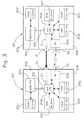
- Figure 3 shows with a block diagram the control systems 20 and 30 of the unit 2 and of the terminal 3, though only those parts thereof that are useful for understanding the aforesaid first aspect of the invention.
- the control system 20 comprises a main module 20a and an auxiliary module 20b, the first one being designed to manage the typical functions of the unit 2 and the second one being designed specifically to manage data transfer with outside.
- the module 20a comprises a main processor 20c operatively associated to a Flash memory 20c', in which the IP_CU address of the unit 2 is coded; as was said, the processor 20c can modify the content of the memory 20c', if necessary.
- the module 20b comprises an auxiliary processor 20d for controlling a circuit 20e for wireless data exchange, including the antenna 2a; the processor 20d can also receive or read external data or information through the serial line 21, connected to the port 5c of the Docking Station 5 (see also Figure 2).
- the processor 20d is operatively associated with a ROM memory 20f, a RAM memory 20g and a Flash memory 20h.
- the series number SN_CU of the unit 2 is coded permanently in the read-only memory 20f, whereas the temporary memory 20g is designed to retain the identifying code ID_CU of the unit 2; conversely, the rewritable memory 20h is designed to retain the identifying code ID_TP of the terminal 3.
- the main 20c and auxiliary processor 20d communicate with each other by means of a bus 20i of the unit 2, such as a CAN bus.
- control system 30 comprises a main module 30a and an auxiliary module 30b, the first one being designed to manage the typical functions of the terminal 3 and the second one being designed to manage data transfer with outside.
- the module 30a comprises a main processor 30c operatively associated to a Flash memory 30c', in which the IP_TP address of the terminal 3 is coded and can be modified if necessary.
- the module 30b comprises an auxiliary processor 30d for controlling a circuit 30e for data exchange by air, including the antenna 3d; the processor 30d can also send data or information or allow these to be read from outside through the serial line 21, connected to the port or connector 3f of the terminal 3 (see also Figure 2).
- the processor 30d is operatively associated with a ROM memory 30f, a RAM memory 30g and a Flash memory 30h.
- the series number SN_TP of the terminal 3 is coded permanently in the read-only memory 30f, whereas the temporary memory 30g contains the identifying code ID_TP of the terminal 3; conversely, the rewritable memory 30h is designed to contain the identifying code ID_CU of the unit 2.
- the main 30c and auxiliary processor 30d communicate with each other by means of a bi-directional serial line 30i.
- the control system 20 when switching on the unit 2, the control system 20 builds the code ID_CU by means of the two processors 20c, 20d and of the memories 20c', 20f, which code is stored in the memory 20g until said unit is switched off; analogously, when switching on the terminal 3, the control system 30 builds the code ID_TP by means of the two processors 30c, 30d and of the memories 30c', 30f, said code being stored in the memory 30g until said terminal is switched off.
- the memories 20g and 30g could, if necessary, be replaced by rewritable permanent memories, such as Flash or EEPROM memories, for containing ID codes also after the devices 2, 3 are switched off.
- the univocal connection between the terminal 3 and the unit 2 - which is required to enable the use of said terminal for programming the robot - is implemented by means of a suitable procedure; in the embodiment described here, said procedure, in the following also defined as "logic coupling" procedure, presupposes that the terminal 3 is positioned on the Docking Station 5 of the unit 2; the coupling of the terminal with a given control unit therefore requires a physical closeness of the two devices.
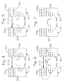
- Figures 4-7 show schematically a possible logic coupling procedure between the unit 2 and the terminal 3.
- FIG 4 shows the situation in which the switched-on terminal 3 is placed on the Docking Station 5.
- a "physical" connection is established between the control systems 20, 30 of the unit 3 and of the terminal 3 by means of the connectors or ports 3f and 5c.
- the control system 20 checks by means of suitable sensor means the actual presence of the terminal 3 on the Docking Station 5 (this can be obtained by using for instance a current sensor belonging to the recharging circuit 22 of Figure 3).
- Figure 5 shows the following step in which, after the confirmation of the presence of the terminal 3, the control system 20 reads the content of the memory 30g of the control system 30, i.e. the identifying code ID_TP of the terminal 3; this is carried out (see also Figure 3) by means of the auxiliary processors 20d and 30d, connected through the serial lines 21, 31 and the ports 3f, 5c. The result of said reading is then stored by the processor 20d in a predefined register of the memory 20h, if said register is free, or compared with the content thereof, if already occupied (such a register can be the one referred to with R0 in Figure 13).
- the control system 20 of the unit 2 communicates its own identifying code ID_CU to the control system 30 of the terminal 3, which in the meanwhile switches to a waiting status.
- the processor 20d reads the content of the memory 20g and transmits the related information in wireless mode together with a coupling instruction by means of the circuit 20e (said transmission can occur thanks to the fact that the system 20 now knows the "identity" of the terminal 3); on the other hand, the coupling instruction with the ID_CU address is received by means of the circuit 30e by the processor 30d, which then stores the related information in a predefined register of the memory 30h, which is free at present.
- said procedure ends with a wireless exchange between the unit 2 and the terminal 3 of information confirming that the logic coupling has occurred.
- the unit 2 and the terminal 3 are coupled with each other, i.e. each of them knows the identifying code ID of the other one, and are therefore enabled to operate in the robot programming mode, in which the terminal 3 can transmit in wireless mode the instructions of motion of the manipulator 1 as well as the required status information concerning the safety devices (i.e. emergency stop device ES and enabling device ED).
- the safety devices i.e. emergency stop device ES and enabling device ED.
- the units in which the aforesaid register of the memory 20g is free will not be enabled to allow manual motion of the respective manipulators.
- the result of the coupling procedure can be made explicit in any way, for instance by means of a visual indication with a suitable lamp or with a display of the unit 2 and/or of the terminal 3.
- ID codes are univocal addresses required for information exchange between the unit 2 and the terminal 3, or better absolutely necessary for enabling the use of the terminal for programming or teaching the robot. Therefore, in the preferred case of data packet transmission from the terminal 3 to the unit 2 during robot programming, the header of a transmitted packet will contain the ID_CU code, whereas the information content of said packet (payload) will concern the transmitted information (about for instance an instruction of motion of the manipulator 1, status information of the emergency stop device, status information of the enabling device). In other words, therefore, any programming and/or motion information, in order to be identified and executed by the unit 2, should be contained in a data packet identified by the ID_CU code.
- the header of a transmitted packet can contain the ID_TP code (but it could also be the address IP_TP), and the information content of said packet will concern the transmitted information (such as an alarm or a machine status, data for updating a window on the display 3, and so on).
- Wireless channels are continuously tested - in a way known per se - through polling procedures on unit 2 and terminal 3 sides with a rate varying depending on the activity of the processor managing communication.
- a decoupling procedure should be executed, as was already mentioned above.
- said procedure should be carried out on the Docking Station 5 of the unit 2 with which the terminal 3 is already coupled; once said decoupling procedure is over, the terminal 3 can be inserted onto the Docking Station 5 of the other unit 2, so as to execute efficiently the corresponding logic coupling procedure.
- Figures 8-11 show schematically a possible logic decoupling procedure between the unit 2 and the terminal 3.
- Figure 8 shows the situation in which the terminal 3, switched on, is on the Docking Station 5, i.e. in a condition as the one of Figure 4.
- the decoupling procedure is started by pressing the pushbutton 5d of the Docking Station 5; here again, in the initial step of the procedure, the actual presence of the terminal 3 on the Docking Station 5 is checked, as was already described above.
- Figure 9 shows the following step in which, after receiving the confirmation of the presence of the terminal 3, the control system 20 reads the content of the memory 30g of the control system 30, i.e. the identifying code ID_TP of the terminal 3, basically as was already described above, through a serial connection. The data resulting from the aforesaid reading is compared by the processor 20d with the content of the aforesaid predefined register of the memory 20h.
- the decoupling procedure is interrupted and a suitable indication is emitted, for instance a visual or acoustic indication, for the operator; the lack of identity between the codes clearly means that the operator is trying to carry out the procedure on a unit 2 other than the one currently allotted to the terminal 3.
- a suitable indication for instance a visual or acoustic indication, for the operator; the lack of identity between the codes clearly means that the operator is trying to carry out the procedure on a unit 2 other than the one currently allotted to the terminal 3.
- the procedure goes on, as shown in Figure 10.
- the processor 20d sends to the control system 30 of the terminal 3 - which in the meanwhile has switched to a waiting status - a decoupling instruction or an instruction of deletion of the content of the memory 30h (see also Figure 3).
- Said instruction is transmitted by the processor 20d in wireless mode by means of the circuit 20e; the information concerning the instruction is received by means of the circuit 30e by the processor 30d, which after sending a suitable confirmation to the unit 2 in wireless mode deletes the memory 30h.
- the processor 20d of the control system 20 of the unit 2 deletes the content of its memory 20h.
- the unit 2 and the terminal 3 are decoupled, i.e. the contents of the memories 20h and 30h of their control systems 20, 30 are free, as shown by way of example in Figure 11; under these circumstances, the terminal 3 is no longer enabled to send the unit 2 instructions of motion of the corresponding manipulator 1.
- the result of the procedure can be made explicit in any way.
- the unit 2 and the terminal 3 are obviously equipped with respective software programs for executing the procedures described with reference to Figures 4-7 and 8-11, said programs being implemented with any technique and known language.
- a cell can comprise both a manipulator and several manipulators, each being equipped with its control unit 2.
- the terminal 3 described above can be used either in a "point-to-point” mode or in a "multipoint” mode.
- the terminal 3 can communicate only with the control unit 2 associated with it.
- the terminal 3 is provided with the full data transmission/reception and programming functions; the operator can thus enter the protected operating area of the manipulator for "teaching" the robot, under these circumstances the safety devices between the terminal 3 and the control unit (emergency stop device ES and enabling device ED) being active.
- the allocation and connection between the terminal 3 and the corresponding unit 2 takes place by means of the dedicated coupling procedure described above, by positioning said terminal on the Docking Station 5 of the concerned unit 2. Under these circumstances, an evident visual indication enables the operator using the terminal 3 to identify the active connection, i.e. the unit 2 which the terminal is currently coupled with.
- a suitable indication can be provided on the display 3a of the terminal 3, on which the "name" of the connected control unit 2 will be displayed; means for signaling the connection are also provided on the control unit 2, in this example the lamp 2c, which will be on continuously for indicating the active connection with the terminal 3.
- the lamp 2c will have such size, color and position as to be well visible (for instance amber color and placed on top of the unit 2 or on its control panel or on the Docking Station 5).
- a lamp 2c can also be mounted onto the manipulator 1 or near the latter.
- the terminal 3 can be simultaneously connected with at least two control units 2 in different modes, and in particular with a so-called “main” or exclusive connection and with at least one so-called “secondary” connection.
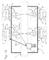
- a generic cell C contains four different robots, referred to with X, Y, W and Z, each having a manipulator 1x, 1y, 1w, 1z with its control unit 2x, 2y, 2w, 2z equipped with its Docking Station 5x, 5y, 5w, 5z and its lamp 2cx, 2cy, 2cw, 2cz.
- the cell is gone through by an advance line L on which two operating stations are present, one being made up of the robots X and Y and the other one of the robots W and Z, the robots of each pair being arranged in a basically symmetrical position with respect to both sides of the line L.
- the terminal 3 has a main connection with the robot X and a secondary connection with the robot W.
- the status of main connection with the robot X - referred to in the figure by the arrow "Main" - basically corresponds to the "point-to-point" mode described above, so that a complete connection is established between the terminal 3 and the unit 2x, safety devices being active and being thus possible to control manually the manipulator 1x to programming purposes.
- the status of secondary connection with the robot W - represented in the figure by the arrow "Secondary" - enables to use the same terminal 3 also for monitoring or remote data exchange functions with respect to the unit 2w (machine status check, current program steps, alarms if present, data download between terminal and control unit and/or vice versa, update of display windows, and so on), though without the possibility of programming or controlling.
- the motion of the corresponding manipulator 1w this because in the secondary connection emergency channels (i.e. those related to the statuses of the safety device ES and enabling device ED) are not active, said channels being active only in the main connection towards the unit 2x.
- the allocation and connection between the terminal 3 and the unit 2x for the main connection should always take place by means of the dedicated procedure described above, by using the Docking Station 5x of the unit 2x. Conversely, the allocation and connection between the terminal 3 and the unit 2w (and the subsequent deactivation of the connection) takes place by means of a software procedure that does not require the terminal to be positioned on the Docking Station 5w.
- the indication of the main connection to the operator belongs to the case of "point-to-point” connection and can therefore be implemented by means of the display 3a of the terminal 3 and the lamp 2cx of the unit 2x, which is steadily on.
- the display 3a of the terminal 3 will show a suitable additional window with the "name" of the unit 2w having a secondary connection; on the other hand, on the unit 2w the lamp 2cw will be blinking, thus indicating the status of secondary connection with the terminal 3.
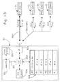
- Figure 13 shows a possible way to implement the "multipoint" connecting function as described above with reference to Figure 12; in said Figure 13 only some components of the control system 30 of the terminal 3 are shown, already described with reference to Figure 3; conversely, the control units 2x, 2y, 2w and 2z of Figure 12 are shown schematically, with the indication of their IP addresses and series numbers SN.
- the rewritable memory 30h of the control system 30 of the terminal 3 comprises a plurality of registers, some of which being referred to with R0, R1, R2, R3, R4; one of said registers, in the case shown by way of example the one referred to with R0, is specifically designed to store the identifying code ID_CD of the control unit which the terminal 3 is coupled with for the main connection or to programming purposes; said storage occurs - as was explained - thanks to the special procedure described with reference to Figures 3 and 4-7.
- the other registers R1, R2, R3 and R4, conversely, are designed to contain respective addresses of secondary connection of the units 2x, 2y, 2w and 2z; in the example shown said addresses consist of the IP addresses of the aforesaid units.
- IP addresses of the units 2x, 2y, 2w and 2z can be pre-stored in the registers R1-R4, for instance upon installation of the cell C with its robots; in such a case, therefore, the IP addresses of the units which the terminal 3 is meant to be able to establish a secondary connection 3 with are inserted into the terminal 3 designed to be used together with a given cell (but it could also be with a plurality of cells, placed for instance on the same manufacturing line).
- the storage of said addresses can be carried out through a simple software procedure directly on the terminal 3, using its display 3a and its keys 3c, and it is not necessarily a permanent storage; as was mentioned, it may happen that the IP address of each control unit (contained in the corresponding memory 20c of Figure 3) must be modified in time, for instance as a result of changes made in time to the cell C; as a consequence, also the content of the registers R1-R4 of the memory 30h of Figure 13 can be modified when necessary.
- the allocation of the secondary connection between the terminal 3 and at least one unit 2x, 2y, 2w and 2z can occur through a radio communication channel, with a variable and dynamic occupation of the registers R1-R4 of the memory 30h.
- the units 2x-2z making up the cell C are programmed so as to declare periodically their IP address in wireless mode; in other words, therefore, the control systems of said units emit at regular intervals by means of their respective circuit 20f (see Figure 3 and its description) a signal containing the IP address information.
- the control system 30 of the terminal 3 is configured so as to switch periodically to a waiting status for receiving said signals; the terminal 3 and the units 2x-2z can be suitably programmed so that the interval with which said terminal switches to a waiting status is a multiple of the interval with which the units emit their address signals.
- the control system 30 of the terminal 3 After the respective circuit 30e has received the aforesaid signals, the control system 30 of the terminal 3 stores the various IP addresses thus received in the registers R1-R.. in sequential order. Obviously, the auxiliary processor 30d compares the IP addresses periodically received with those that might already be stored in the addresses R1-R.., so as to avoid a double storage of the same information.
- the terminal 3 can conversely be configured so as to "summon" for the secondary connection the units 2x-2z that might be available in the network.
- the control system 30 of the latter emits cyclically for a given lapse of time and by means of the circuit 30e a query signal, i.e. an invitation to the resources available in the network to "introduce themselves", and then switches to a response waiting status; after receiving said query signal through the respective circuits 20e, the control units available in the network transmit through said circuits 20e their IP address signals, which the terminal 3 receives and then stores in the registers R1-R4, basically in the same way as described above.
- the control systems of the units 2x-2z will cyclically switch to a waiting status for receiving the aforesaid query signal; the terminal 3 and the units 2x-2z can be programmed, if necessary, so that the interval with which said units switch to a waiting status is a submultiple of the lapse of time during which the terminal emits cyclically the query signal; on the other hand, the response waiting time for the terminal 3 - after the emission of a query signal - can be a multiple of the interval imposed to the units for emitting their address signals.
- the system can be conceived so that at least one secondary connection can be enabled only if the terminal 3 already has a main connection, i.e. it is logically coupled with one of the control units; the system can further be configured so that the control unit that already has a main connection with the terminal 3 (in the example of Figure 13 unit 2x) does not communicate its IP address for the storage in one of the registers R1-R.. of the memory 30h, since it is unnecessary.
- control systems 2x-2z can be configured so as to communicate to the terminal 3, beside their IP address, also further identifying information enabling the operator a visual identification of the various units, whatever the status of the lamps 2cx-2cz, i.e. also before the secondary connection is established.
- the various units 2x-2z and/or their manipulators 1x-1z can be equipped in a well visible position with a plate indicating a robot name in alphabetical, numeric or alphanumeric characters; with reference to the example of Figures 12-13, said name can be made up of the series number SN, and therefore "4", "8", “7” and "2" for robots X, Y, W and Z, respectively.
- the terminal 3 can associate each IP address also with a "label" of the corresponding robot, so as to show it on the display 3a.
- a selection window can be activated on the display 3a, so as to display the list of labels of the units which can establish a secondary connection with the terminal 3; after visual identification in the cell C (through the corresponding plate) of the robot with which the secondary connection should be established, the operator can select the corresponding label by means of the aforesaid window and thanks to the keyboard of the terminal 3.
- the operator using the terminal 3 can activate a different secondary connection by simply recalling on the display 3a the aforesaid display window and choosing from the corresponding list the label of another robot; said possibility is shown by way of example by the hatched arrows of Figure 13.
- the software which the terminal 3 is equipped with is provided with suitable menus or functions for selecting the windows to be shown on the display 3a, and it is therefore possible to switch between the connection windows "Main" and "Secondary".
- the portable terminal 3 in order to enable a robot for programming/motion functions, the portable terminal 3 should be placed in a given position with respect to the control unit 2, so as to start a suitable logic coupling procedure.
- said coupling can be obtained only as a result of the physical approach between said two devices, and in particular after placing the terminal 3 in a suitable support 5 belonging to the unit 2; thus, the operator that should use the terminal 3 is indeed forced to pre-identify visually which one of the robots present in the working area C can be moved manually.
- the proposed solution does not make the implementation of the terminal 3 particularly difficult, since it involves at most only the addition of some internal electronic components (if they are not already present) and of an auxiliary communication line for transferring the identifying code ID_TP (moreover, in case of use of power line communication - as explained below - the port 3f and the serial line 31 can be omitted); the absence of a dedicated seat for a removable module, as provided for in WO 02/078913 , simplifies the layout of the terminal, which can thus be compact and light.
- the unit 2 is equipped with a support or seat with some elementary and/or standard contacts, in which the terminal should be placed.
- a wireless terminal necessarily includes a battery, preferably a rechargeable battery; advantageously, therefore, means that should in any case be present so as to recharge the terminal battery can be exploited, in the preferred embodiment of the invention, for integrating also part of the means enabling to couple logically the terminal and the control unit with one another.
- a robot can operate in an automatic operation mode.
- the robots X-Z execute their operating programs inside the cell C, which the personnel cannot enter but is under the visual control of an operator.
- the portable terminal 3 can be placed - as occurs typically - in a stationary position near the cell C, though the emergency stop pushbutton ES being active, by means of which the operator can stop the robot X and/or - as provided in many cases - the whole cell C, if necessary.
- the function associated with the pushbutton ES is active only in case of a "Main" connection between a robot and the terminal 3, the latter being allowed, according to the second aspect of the invention, to establish selectively at least also one "Secondary" connection.
- the operator monitoring the cell C can monitor remotely the control systems of the various robots X-Y by means of the terminal 3 and therefore from only one place, without having to move continuously near each of the units 2x-2z for checking their machine statuses on their control panels.
- the "multipoint" connection mode further enables to simplify the programming activity of systems in which several robots execute basically similar operations.
- a cell C often contains several working stations on the same line L, each station having two robots in opposite positions; in the case shown two stations are present, including robots X-Y and W-Z, respectively.
- the two robots of the same station execute automatically identical operations on opposite portions of the same part on the line L, the basic movements of one robot being therefore perfectly symmetrical or inverse with respect to those executed by the other robot.
- the operating program of the first robot differs from the one of the second robot only for a given series of parameters (such as position coordinates of the joints of the manipulator or the direction of movement of its parts, within a given space reference system).
- Logic coupling and decoupling procedures could be started, instead with the key 5d, by means of an instruction given by the terminal 3, provided the latter has been previously positioned on the Docking Station 5 of the concerned unit 2.
- the control system 30 of the terminal can communicate its own code ID_TP to the control system 20 of the unit 2 by means of the serial connection made up of the components previously referred to with 31, 3f, 3c and 21 (if necessary, the terminal 3 could read the code ID_CU of the system 20, and the coupling/decoupling procedure could take place inversely with respect to the one described previously, managed by the system 30).
- the connection due to the positioning of the terminal 3 near the unit 2 can be obtained with different means with respect to a cabled serial line, and in particular with a connection without physical or dedicated contacts.
- the information concerning at least one ID code could be transferred using RFID technology, with at least one tag associated with the terminal 3 and at least one corresponding tag reader associated with the unit 2 and/or with its manipulator 1; in said application, the components of the RFID system are preferably sized so as to have a useful range of few centimeters, so that the information can be transferred only when the terminal 3 is positioned on the Docking Station 5 or close to the unit 2 and/or to the manipulator 1.
- Another possibility involves the use of an infrared interface, i.e.
- the Docking Station 5 or the means replacing it for the coupling/decoupling procedure could be placed near the manipulator 1.
Abstract
Description
- The present invention relates to industrial robots and was conceived in particular for the possible application of robots with a portable terminal associated therewith and designed to communicate in wireless mode with the robot control unit.
- "Wireless" refers here to a communication involving a wireless communication of signals by means of electromagnetic waves, preferably by radio-frequency but possibly also by means of ultrasounds or infrared radiations or radiations in another frequency field.
- Programming a robot basically means teaching said robot the trajectory which a point of its manipulator should repeat automatically during normal operating steps in order to execute a given operation. A robot can thus operate at least in an automatic and in a manual mode, which can usually be selected on the robot control unit. When manual mode is selected, for instance for programming or "teaching" a robot, the respective manipulator can be handled through instructions sent by a portable terminal; conversely, when automatic operation mode is selected, the motion of the manipulator is subject only to the control unit.
- Most of the programming time is for manually controlling the robot, so as to identify the optimal points of the motion trajectories of the manipulator and store the coordinates thereof. To this purpose the aforesaid portable programming terminal is used, also known as teach pendant, which is operatively connected to the robot control unit and typically comprises a display and a series of pushbuttons used for programming and manually controlling the robot. The teach pendant can also be used for monitoring the robot program, for checking machine statuses, for modifying certain program parameters and so on.
- In some solutions the terminal is connected to the control unit by means of a cable having such a length as to enable the operator to move near the working area of the manipulator and accurately check related points and trajectories. The aforesaid cable enables a limited controllability for the operator in his/her programming activity, since s/he should move continuously near the manipulator; another drawback consists in that the cable can get caught or entangled with other cables and should thus be freed. Moreover, the cable is subject to wear and tear and damages and therefore needs to be repaired or replaced. In order to solve such drawbacks it has been suggested to operatively connect the portable terminal to the control unit in wireless mode.
- The operating environment in which a robot performs its functions, known as "cell", has different configurations depending on the system layout and can contain one manipulator or more manipulators operating coordinately, each manipulator being equipped with its control unit. The use of wireless data exchange technology has a further advantage consisting in that one teach pendant can be used for controlling in manual mode each of the robots of a cell independently so as to program the latter. However, when one of the robots of a cell has to be placed under the manual control of a wireless teach pendant, it is extremely important to establish a definite univocal connection between the teach pendant and the robot to be controlled, so as to avoid possible dangers for the programming operator.
-
WO 02/078913 - The solution mentioned above complicates to a certain extent the implementation of the portable terminal, which should be equipped with a suitable seat and with related means of physical interconnection for the removable module; removable modules are further subject to frequent handlings, which might engender confusions as well as damages and a rapid wear and tear of their contacts, with subsequent risks of bad working.
- In the light of the above, the present invention aims at implementing an industrial robot as previously referred to, ensuring an improved level of safety as far as programming activity is concerned, and whose manufacture is simple, cheap and reliable. The invention further aims at implementing a robot as previously referred to which enables an easy and versatile activity involving programming and manual control by means of a portable terminal, however under fully safe conditions.
- These and other aims, which will be clear in the following, are achieved according to the invention by a process, an industrial robot, a robot system and a computer product having the features listed in the appended claims, which are an integral and substantial part of the description of the present patent application.
- Further aims, characteristics and advantages of the invention will be evident from the following description and from the accompanying drawings, given as mere illustrative and non-limiting example, in which:
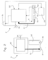
- Figure 1 schematically shows a robot as described here, comprising a manipulator, a control unit of the manipulator and a portable programming terminal;
- Figure 2 shows a simplified block diagram of the control unit and of the terminal of the robot of Figure 1;
- Figure 3 shows a simplified block diagram of a part of the control systems of the unit and of the terminal of Figure 2;
- Figures 4-7 are schematic representations of the steps of a logic coupling procedure between the control unit and the terminal of Figure 3;
- Figures 8-11 are schematic representations of the steps of a logic decoupling procedure between the control unit and the terminal of Figure 3;
- Figure 12 is a schematic representation of a working cell comprising a robot system as described here;
- Figure 13 is a simplified block diagram disclosing a possible use of a terminal used in the robot system of Figure 12.
Figure 1 shows an industrial robot comprising a manipulator 1, acontrol unit 2 and a portable programming terminal or teachpendant 3. The manipulator 1 has a plurality of parts moving according to respective axes, articulated by means of joints 1a, and an end wrist 1b carrying a generic tool 1c. The manipulator 1 is connected by means of acable 4 to itscontrol unit 2. Theterminal 3 comprises at least - a
display 3a, by means of which machine statuses, programming steps, possible alarms and various parameters, such as the position of the axes of the manipulator, can be monitored; thedisplay 3a is used both when programming the positions of the axes and the steps of a movement program and as remote monitor for theunit 2; - a group of keys for controlling the motion of the axes of the manipulator 1, some of which are referred to with 3b; the keys of said groups comprise in particular those for selecting the desired motion reference system and those for controlling motion, known as "jog" keys;
- a group of programming and editing keys, some of which are schematically referred to with 3c, used for surfing inside programs shown on the display. 3b, for activating various functions and for inputting data.
- The
terminal 3 further comprises an emergency stop device, referred to with ES, which can consist of a mushroom pushbutton, placed in fixed position on the front panel of said terminal; pressing said pushbutton enables to immediately stop/deactivate the motion of the manipulator 1 and/or of the whole operating cell in which the robot operates. The teach pendant is also equipped with an enabling device, referred to with ED, which should be used together with the keys of thegroup 3c during the teaching steps or the steps of manual control of the motion of the manipulator 1; in practice, the enabling device ED should be kept active by the operator, so as to enable the manipulator 1 to make the desired movements during the programming step. In the non-limiting example of Figure 1, the device ED comprises two keys extending on the lateral edges of theterminal 3, but in another possible embodiment the device can be located in the rear portion of the terminal, as described for instance in documentEP-A-1 405 700 . - The
unit 2 and theterminal 3 are configured so as to communicate with each other in wireless mode, and to this purpose they are equipped with means for exchanging signals by air, comprisingrespective antennae 2a and 3d. Said means are sized so as to have a useful range of a few meters and therefore to be inside the field of action ofterminal 3 with respect to theunit 2. Air transmission of signals can occur according to any known technique; in the preferred embodiment of the invention, wireless communication betweenunit 2 andterminal 3 takes place by radio-frequency, using the transmission system defined by standard IEEE 802.111 (which is wholly referred to for further details), known as Wi-fi system. - The wireless connection between the
terminal 3 and theunit 2 basically enables the exchange of the three following types of information: - a) operating data, such as information concerning axis position, motion or jog instructions and in general all selections that can be made by means of the
terminal 3, as well as software download from said terminal to theunit 2; also theunit 2 can send data to theterminal 3, such as information required for updating windows on thedisplay 3a, indication codes (alarms, machine statuses, and so on), program upload, and so on; - b) status of the emergency stop device ES;
- c) status of the enabling device ED.
- The
terminal 3 further comprises anelectric connector 3e belonging to a recharging arrangement of an internal battery of said terminal, and a port fordata transfer 3f, which is supposed to be here the connector of a serial communication port. In the disclosed non-limiting example, theconnector 3e and theport 3f are positioned on the lower edge of theterminal 3. - According to a first aspect of the invention, in order to allocate or couple univocally the
terminal 3 and thecontrol unit 2, the first one should be first positioned near the second one, or more generally in a predefined position. To this purpose, in the preferred embodiment of the invention, theunit 2 is provided with apositioning support 5 for theterminal 3, defined in the following as Docking Station; advantageously, the DockingStation 5 is configured so as to be used also for recharging an internal battery of theterminal 3. - The Docking
Station 5 is preferably connected physically to the cabinet orstationary frame 2b of theunit 2, and for simplicity's sake, in the example it is configured as a sort of shelf defining aseat 5a open upwards; the lower portion of theterminal 3 can be inserted into theseat 5a in the direction of arrow F of Figure 1. Anelectric connector 5b and a connector or port fordata transfer 5c, which are complementary toconnectors 3e and toport 3f, are fastened onto the bottom of saidseat 5a. The insertion of the lower portion of theterminal 3 into theseat 5a results in the coupling or connection both between theconnectors ports - The Docking Station is further equipped with a control element, such as a
pushbutton 5d, used for starting a logic coupling-decoupling procedure between theterminal 3 and theunit 2, which is a further independent aspect of the present invention to be protected. - Still in Figure 1, eventually, 2c refers to a signaling lamp indicating an interoperating condition between the
unit 2 and theterminal 3. - In Figure 2 the
unit 2 and theterminal 3 are represented by means of simplified block diagrams. - The
terminal 3 comprises a corresponding electronic control system, globally referred to with 30, for managing all the various functions of said terminal. Thesystem 30 can send and receive data or information through theantenna 3d and it is further configured so as to enable data and information transfer through a further data communication line, here a physical or cable line, such as a serial unidirectional line, referred to with 31, connected to theport 3f.Number 32 refers to an autonomous supply source of the terminal, such as a rechargeable battery known per se, whose poles are connected to the contacts of theconnector 3e. - The
unit 2 comprises a corresponding electronic control system, globally referred to with 20, for managing all the various functions of said unit. Thesystem 20 is configured so as to send and receive data or information through theantenna 2a; thesystem 20 is also configured so as to enable data and information transfer through a further data communication line, here a physical or cabled line, such as a serial unidirectional line, referred to with 21, connected to theport 5c of the DockingStation 5. -
Number 22 refers to a recharging circuit, known per se, controlled by thesystem 20 and connected to theconnector 5b of the Docking Station. Thesystem 20 is further configured so as to control the operation of thelamp 2c, as well as to receive a control signal from thepushbutton 5d. - In order to enable the use of the
terminal 3 for programming the robot, both theunit 2 and theterminal 3 are equipped with a corresponding univocal identifying code ID. Each ID code is preferably made up of two parts, represented by an IP network address (but it could be a MAC address) and by a series number SN.
Thus:

where - ID_CU and ID_TP refer to the identifying codes of the
unit 2 and of theterminal 3, respectively; - IP_CU and SN_CU refer to the IP address and to the univocal series number SN of the
unit 2, respectively; - IP_TP and SN_TP refer to the IP address and to the univocal series number SN of the
terminal 3, respectively. - For simplicity's sake and referring to the accompanying figures, let us suppose that IP_CU and IP_TP addresses are 4 and 2, that SN_CU and SN_TP series numbers are 4 and 5, and that, therefore, ID_CU and ID_TP identifying codes are 44 and 25, respectively.
- IP addresses can be modified depending on the various needs, in ways that are not described here since they are known per se and do not fall within the scope of the present invention; to this purpose, IP addresses can be stored on rewritable permanent memories, such as Flash or EEPROM memories. Preferably, series numbers SN cannot be modified, and to this purpose they can be written by the manufacturer of the
unit 2 and/or of theterminal 3 during manufacturing and/or test steps on permanent read-only memories, such as ROM memories. The identifying code ID is built by the control system of theunit 2 and of theterminal 3 after their switching on, and stored in a rewritable memory, for instance a RAM, Flash or EEPROM memory. - Figure 3 shows with a block diagram the
control systems unit 2 and of theterminal 3, though only those parts thereof that are useful for understanding the aforesaid first aspect of the invention. - The
control system 20 comprises amain module 20a and anauxiliary module 20b, the first one being designed to manage the typical functions of theunit 2 and the second one being designed specifically to manage data transfer with outside. Themodule 20a comprises amain processor 20c operatively associated to aFlash memory 20c', in which the IP_CU address of theunit 2 is coded; as was said, theprocessor 20c can modify the content of thememory 20c', if necessary. Themodule 20b comprises anauxiliary processor 20d for controlling acircuit 20e for wireless data exchange, including theantenna 2a; theprocessor 20d can also receive or read external data or information through theserial line 21, connected to theport 5c of the Docking Station 5 (see also Figure 2). Theprocessor 20d is operatively associated with aROM memory 20f, aRAM memory 20g and aFlash memory 20h. The series number SN_CU of theunit 2 is coded permanently in the read-only memory 20f, whereas thetemporary memory 20g is designed to retain the identifying code ID_CU of theunit 2; conversely, therewritable memory 20h is designed to retain the identifying code ID_TP of theterminal 3. The main 20c andauxiliary processor 20d communicate with each other by means of a bus 20i of theunit 2, such as a CAN bus. - Also the
control system 30 comprises amain module 30a and anauxiliary module 30b, the first one being designed to manage the typical functions of theterminal 3 and the second one being designed to manage data transfer with outside. Themodule 30a comprises amain processor 30c operatively associated to aFlash memory 30c', in which the IP_TP address of theterminal 3 is coded and can be modified if necessary. Themodule 30b comprises anauxiliary processor 30d for controlling acircuit 30e for data exchange by air, including theantenna 3d; theprocessor 30d can also send data or information or allow these to be read from outside through theserial line 21, connected to the port orconnector 3f of the terminal 3 (see also Figure 2). Here too, theprocessor 30d is operatively associated with aROM memory 30f, aRAM memory 30g and aFlash memory 30h. The series number SN_TP of theterminal 3 is coded permanently in the read-only memory 30f, whereas thetemporary memory 30g contains the identifying code ID_TP of theterminal 3; conversely, therewritable memory 30h is designed to contain the identifying code ID_CU of theunit 2. The main 30c andauxiliary processor 30d communicate with each other by means of a bi-directional serial line 30i. - As was already mentioned, when switching on the
unit 2, thecontrol system 20 builds the code ID_CU by means of the twoprocessors memories 20c', 20f, which code is stored in thememory 20g until said unit is switched off; analogously, when switching on theterminal 3, thecontrol system 30 builds the code ID_TP by means of the twoprocessors memories 30c', 30f, said code being stored in thememory 30g until said terminal is switched off. Thememories devices - According to the first relevant aspect of the solution described here, the univocal connection between the terminal 3 and the unit 2 - which is required to enable the use of said terminal for programming the robot - is implemented by means of a suitable procedure; in the embodiment described here, said procedure, in the following also defined as "logic coupling" procedure, presupposes that the
terminal 3 is positioned on theDocking Station 5 of theunit 2; the coupling of the terminal with a given control unit therefore requires a physical closeness of the two devices. - Figures 4-7 show schematically a possible logic coupling procedure between the
unit 2 and theterminal 3. - Figure 4 shows the situation in which the switched-on
terminal 3 is placed on theDocking Station 5. Under such circumstances, as was explained, a "physical" connection is established between thecontrol systems unit 3 and of theterminal 3 by means of the connectors orports pushbutton 5d of theDocking Station 5 an operator starts the coupling procedure; in the initial step of said procedure thecontrol system 20 checks by means of suitable sensor means the actual presence of theterminal 3 on the Docking Station 5 (this can be obtained by using for instance a current sensor belonging to therecharging circuit 22 of Figure 3). - Figure 5 shows the following step in which, after the confirmation of the presence of the
terminal 3, thecontrol system 20 reads the content of thememory 30g of thecontrol system 30, i.e. the identifying code ID_TP of theterminal 3; this is carried out (see also Figure 3) by means of theauxiliary processors serial lines ports processor 20d in a predefined register of thememory 20h, if said register is free, or compared with the content thereof, if already occupied (such a register can be the one referred to with R0 in Figure 13). The fact that the aforesaid register of thememory 20h is free means that theterminal 3 is not coupled at present with anyunit 2, whereas the condition in which thememory register 20h is already occupied means that theterminal 3 is already coupled with a control unit. In practice, the three following situations can occur: - a) if the aforesaid register of the
memory 20h is free, the operator is correctly trying to establish a logic coupling procedure between theunit 2 on whoseDocking Station 5 the terminal is now positioned; - b) if the ID_TP code read is the same as the one stored in the aforesaid register of the
memory 20h, the operator is correctly trying to establish a logic decoupling procedure, as will be described in further detail below; - c) if the ID_TP code read differs from the one stored in the aforesaid register of the
memory 20h, the operator is incorrectly trying to establish a coupling procedure with a terminal already coupled with another unit, or s/he is incorrectly trying to establish a decoupling procedure on the Docking Station of a control unit differing from the one with which the terminal is currently coupled (which is not allowed, as will be discussed below). - In cases b) and c) the
unit 2 emits a suitable error signal; in case a), conversely, the coupling procedure can go on to the next step, shown in Figure 6. - During said step, after memorizing the ID_TP code the
control system 20 of theunit 2 communicates its own identifying code ID_CU to thecontrol system 30 of theterminal 3, which in the meanwhile switches to a waiting status. To this purpose (see also Figure 3) theprocessor 20d reads the content of thememory 20g and transmits the related information in wireless mode together with a coupling instruction by means of thecircuit 20e (said transmission can occur thanks to the fact that thesystem 20 now knows the "identity" of the terminal 3); on the other hand, the coupling instruction with the ID_CU address is received by means of thecircuit 30e by theprocessor 30d, which then stores the related information in a predefined register of thememory 30h, which is free at present. Preferably, said procedure ends with a wireless exchange between theunit 2 and theterminal 3 of information confirming that the logic coupling has occurred. - Now, as shown by way of example in Figure 7, the
unit 2 and theterminal 3 are coupled with each other, i.e. each of them knows the identifying code ID of the other one, and are therefore enabled to operate in the robot programming mode, in which theterminal 3 can transmit in wireless mode the instructions of motion of the manipulator 1 as well as the required status information concerning the safety devices (i.e. emergency stop device ES and enabling device ED). - As can be inferred, in case of systems comprising several robots, the units in which the aforesaid register of the
memory 20g is free will not be enabled to allow manual motion of the respective manipulators. - The result of the coupling procedure can be made explicit in any way, for instance by means of a visual indication with a suitable lamp or with a display of the
unit 2 and/or of theterminal 3. - In the system described here, ID codes are univocal addresses required for information exchange between the
unit 2 and theterminal 3, or better absolutely necessary for enabling the use of the terminal for programming or teaching the robot. Therefore, in the preferred case of data packet transmission from theterminal 3 to theunit 2 during robot programming, the header of a transmitted packet will contain the ID_CU code, whereas the information content of said packet (payload) will concern the transmitted information (about for instance an instruction of motion of the manipulator 1, status information of the emergency stop device, status information of the enabling device). In other words, therefore, any programming and/or motion information, in order to be identified and executed by theunit 2, should be contained in a data packet identified by the ID_CU code. - On the other hand, in case of transmission from the
unit 2 to theterminal 3, the header of a transmitted packet can contain the ID_TP code (but it could also be the address IP_TP), and the information content of said packet will concern the transmitted information (such as an alarm or a machine status, data for updating a window on thedisplay 3, and so on). - Wireless channels are continuously tested - in a way known per se - through polling procedures on
unit 2 and terminal 3 sides with a rate varying depending on the activity of the processor managing communication. - When the
terminal 3 should be used together with a "new" unit 2 (i.e. a unit differing from the one with which the terminal is coupled at present), a decoupling procedure should be executed, as was already mentioned above. In the preferred embodiment of the invention, said procedure should be carried out on theDocking Station 5 of theunit 2 with which theterminal 3 is already coupled; once said decoupling procedure is over, theterminal 3 can be inserted onto theDocking Station 5 of theother unit 2, so as to execute efficiently the corresponding logic coupling procedure. - Figures 8-11 show schematically a possible logic decoupling procedure between the
unit 2 and theterminal 3. - Figure 8 shows the situation in which the
terminal 3, switched on, is on theDocking Station 5, i.e. in a condition as the one of Figure 4. The decoupling procedure is started by pressing thepushbutton 5d of theDocking Station 5; here again, in the initial step of the procedure, the actual presence of theterminal 3 on theDocking Station 5 is checked, as was already described above. - Figure 9 shows the following step in which, after receiving the confirmation of the presence of the
terminal 3, thecontrol system 20 reads the content of thememory 30g of thecontrol system 30, i.e. the identifying code ID_TP of theterminal 3, basically as was already described above, through a serial connection. The data resulting from the aforesaid reading is compared by theprocessor 20d with the content of the aforesaid predefined register of thememory 20h. If the read ID_TP code differs from the one contained in said register, the decoupling procedure is interrupted and a suitable indication is emitted, for instance a visual or acoustic indication, for the operator; the lack of identity between the codes clearly means that the operator is trying to carry out the procedure on aunit 2 other than the one currently allotted to theterminal 3. Conversely, in case of correspondence between the two data (read ID_TP and stored ID_TP), the procedure goes on, as shown in Figure 10. - During this step the
processor 20d sends to thecontrol system 30 of the terminal 3 - which in the meanwhile has switched to a waiting status - a decoupling instruction or an instruction of deletion of the content of thememory 30h (see also Figure 3). Said instruction is transmitted by theprocessor 20d in wireless mode by means of thecircuit 20e; the information concerning the instruction is received by means of thecircuit 30e by theprocessor 30d, which after sending a suitable confirmation to theunit 2 in wireless mode deletes thememory 30h. Upon reception of said confirmation, theprocessor 20d of thecontrol system 20 of theunit 2 deletes the content of itsmemory 20h. - Now the
unit 2 and theterminal 3 are decoupled, i.e. the contents of thememories control systems terminal 3 is no longer enabled to send theunit 2 instructions of motion of the corresponding manipulator 1. Here again, the result of the procedure can be made explicit in any way. - The
unit 2 and theterminal 3 are obviously equipped with respective software programs for executing the procedures described with reference to Figures 4-7 and 8-11, said programs being implemented with any technique and known language. - As was explained in the introduction of the present description, a cell can comprise both a manipulator and several manipulators, each being equipped with its
control unit 2. In case of a system comprising several robots, theterminal 3 described above can be used either in a "point-to-point" mode or in a "multipoint" mode. - In the first case the
terminal 3 can communicate only with thecontrol unit 2 associated with it. In this configuration of use theterminal 3 is provided with the full data transmission/reception and programming functions; the operator can thus enter the protected operating area of the manipulator for "teaching" the robot, under these circumstances the safety devices between the terminal 3 and the control unit (emergency stop device ES and enabling device ED) being active. The allocation and connection between the terminal 3 and thecorresponding unit 2 takes place by means of the dedicated coupling procedure described above, by positioning said terminal on theDocking Station 5 of theconcerned unit 2. Under these circumstances, an evident visual indication enables the operator using theterminal 3 to identify the active connection, i.e. theunit 2 which the terminal is currently coupled with. To this purpose a suitable indication can be provided on thedisplay 3a of theterminal 3, on which the "name" of theconnected control unit 2 will be displayed; means for signaling the connection are also provided on thecontrol unit 2, in this example thelamp 2c, which will be on continuously for indicating the active connection with theterminal 3. Thelamp 2c will have such size, color and position as to be well visible (for instance amber color and placed on top of theunit 2 or on its control panel or on the Docking Station 5). Note that as an alternative or in addition to the case just described, alamp 2c can also be mounted onto the manipulator 1 or near the latter. - In case of "multipoint" mode in accordance with a second independent aspect of the invention to be protected, the
terminal 3 can be simultaneously connected with at least twocontrol units 2 in different modes, and in particular with a so-called "main" or exclusive connection and with at least one so-called "secondary" connection. Such a case is shown schematically by way of example in Figure 12, where a generic cell C contains four different robots, referred to with X, Y, W and Z, each having a manipulator 1x, 1y, 1w, 1z with itscontrol unit Docking Station - In the example, the robot X basically corresponds to the robot of Figure 1, whose
unit 2x is characterized by the codes IP=4 and SN=4 (and therefore with a code ID_CU=44) as in the example described above; conversely, the codes of the other robots are the following:unit 2y: IP=5, SN=8;unit 2w: IP=6, SN=7;unit 2z: IP=7, SN=2. - In the situation shown above, the
terminal 3 has a main connection with the robot X and a secondary connection with the robot W. The status of main connection with the robot X - referred to in the figure by the arrow "Main" - basically corresponds to the "point-to-point" mode described above, so that a complete connection is established between the terminal 3 and theunit 2x, safety devices being active and being thus possible to control manually the manipulator 1x to programming purposes. - The status of secondary connection with the robot W - represented in the figure by the arrow "Secondary" - enables to use the
same terminal 3 also for monitoring or remote data exchange functions with respect to theunit 2w (machine status check, current program steps, alarms if present, data download between terminal and control unit and/or vice versa, update of display windows, and so on), though without the possibility of programming or controlling.the motion of the corresponding manipulator 1w: this because in the secondary connection emergency channels (i.e. those related to the statuses of the safety device ES and enabling device ED) are not active, said channels being active only in the main connection towards theunit 2x. - The allocation and connection between the terminal 3 and the
unit 2x for the main connection should always take place by means of the dedicated procedure described above, by using theDocking Station 5x of theunit 2x. Conversely, the allocation and connection between the terminal 3 and theunit 2w (and the subsequent deactivation of the connection) takes place by means of a software procedure that does not require the terminal to be positioned on theDocking Station 5w. - The indication of the main connection to the operator belongs to the case of "point-to-point" connection and can therefore be implemented by means of the
display 3a of theterminal 3 and the lamp 2cx of theunit 2x, which is steadily on. As far as indications of the secondary connection are concerned, on one hand thedisplay 3a of theterminal 3 will show a suitable additional window with the "name" of theunit 2w having a secondary connection; on the other hand, on theunit 2w the lamp 2cw will be blinking, thus indicating the status of secondary connection with theterminal 3. - Figure 13 shows a possible way to implement the "multipoint" connecting function as described above with reference to Figure 12; in said Figure 13 only some components of the
control system 30 of theterminal 3 are shown, already described with reference to Figure 3; conversely, thecontrol units - As shown by way of example in Figure 13, the
rewritable memory 30h of thecontrol system 30 of theterminal 3 comprises a plurality of registers, some of which being referred to with R0, R1, R2, R3, R4; one of said registers, in the case shown by way of example the one referred to with R0, is specifically designed to store the identifying code ID_CD of the control unit which theterminal 3 is coupled with for the main connection or to programming purposes; said storage occurs - as was explained - thanks to the special procedure described with reference to Figures 3 and 4-7. - The other registers R1, R2, R3 and R4, conversely, are designed to contain respective addresses of secondary connection of the
units - In a possible embodiment, IP addresses of the
units terminal 3 is meant to be able to establish asecondary connection 3 with are inserted into theterminal 3 designed to be used together with a given cell (but it could also be with a plurality of cells, placed for instance on the same manufacturing line). The storage of said addresses can be carried out through a simple software procedure directly on theterminal 3, using itsdisplay 3a and itskeys 3c, and it is not necessarily a permanent storage; as was mentioned, it may happen that the IP address of each control unit (contained in thecorresponding memory 20c of Figure 3) must be modified in time, for instance as a result of changes made in time to the cell C; as a consequence, also the content of the registers R1-R4 of thememory 30h of Figure 13 can be modified when necessary. - As an alternative, the allocation of the secondary connection between the terminal 3 and at least one
unit memory 30h. - In a first possible embodiment of this type, the
units 2x-2z making up the cell C are programmed so as to declare periodically their IP address in wireless mode; in other words, therefore, the control systems of said units emit at regular intervals by means of theirrespective circuit 20f (see Figure 3 and its description) a signal containing the IP address information. On the other hand, thecontrol system 30 of theterminal 3 is configured so as to switch periodically to a waiting status for receiving said signals; theterminal 3 and theunits 2x-2z can be suitably programmed so that the interval with which said terminal switches to a waiting status is a multiple of the interval with which the units emit their address signals. - After the
respective circuit 30e has received the aforesaid signals, thecontrol system 30 of the terminal 3 stores the various IP addresses thus received in the registers R1-R.. in sequential order. Obviously, theauxiliary processor 30d compares the IP addresses periodically received with those that might already be stored in the addresses R1-R.., so as to avoid a double storage of the same information. - In accordance with another possible embodiment, the
terminal 3 can conversely be configured so as to "summon" for the secondary connection theunits 2x-2z that might be available in the network. In said situation, therefore, automatically or as a result of a specific instruction entered by the operator on theterminal 3, thecontrol system 30 of the latter emits cyclically for a given lapse of time and by means of thecircuit 30e a query signal, i.e. an invitation to the resources available in the network to "introduce themselves", and then switches to a response waiting status; after receiving said query signal through therespective circuits 20e, the control units available in the network transmit through saidcircuits 20e their IP address signals, which theterminal 3 receives and then stores in the registers R1-R4, basically in the same way as described above. Obviously, in this embodiment the control systems of theunits 2x-2z will cyclically switch to a waiting status for receiving the aforesaid query signal; theterminal 3 and theunits 2x-2z can be programmed, if necessary, so that the interval with which said units switch to a waiting status is a submultiple of the lapse of time during which the terminal emits cyclically the query signal; on the other hand, the response waiting time for the terminal 3 - after the emission of a query signal - can be a multiple of the interval imposed to the units for emitting their address signals. - The system can be conceived so that at least one secondary connection can be enabled only if the
terminal 3 already has a main connection, i.e. it is logically coupled with one of the control units; the system can further be configured so that the control unit that already has a main connection with the terminal 3 (in the example of Figure 13unit 2x) does not communicate its IP address for the storage in one of the registers R1-R.. of thememory 30h, since it is unnecessary. - If required, the
control systems 2x-2z can be configured so as to communicate to theterminal 3, beside their IP address, also further identifying information enabling the operator a visual identification of the various units, whatever the status of the lamps 2cx-2cz, i.e. also before the secondary connection is established. For instance, referring to the example of Figure 12-13, thevarious units 2x-2z and/or their manipulators 1x-1z can be equipped in a well visible position with a plate indicating a robot name in alphabetical, numeric or alphanumeric characters; with reference to the example of Figures 12-13, said name can be made up of the series number SN, and therefore "4", "8", "7" and "2" for robots X, Y, W and Z, respectively. By sending the aforesaid additional identifying information and by storing the latter in a suitable memory thanks to thecontrol system 30, theterminal 3 can associate each IP address also with a "label" of the corresponding robot, so as to show it on thedisplay 3a. Thus, a selection window can be activated on thedisplay 3a, so as to display the list of labels of the units which can establish a secondary connection with theterminal 3; after visual identification in the cell C (through the corresponding plate) of the robot with which the secondary connection should be established, the operator can select the corresponding label by means of the aforesaid window and thanks to the keyboard of theterminal 3. As a result of said selection, the status of "Secondary" connection will be shown on thecontrol unit 2w (in the example of Figure 12-13) by blinking of the corresponding lamp 2cw; thedisplay 3a of theterminal 3, conversely, will show a dialog window containing, beside the label of the robot W, the various options allowed by the secondary connection; as was said, said options refer basically to the possible remote monitoring of theunit 2w and to the exchange of data and information differing from programming/motion data and information of the manipulator 1w, which are not allowed by the secondary connection. - At any time, the operator using the
terminal 3 can activate a different secondary connection by simply recalling on thedisplay 3a the aforesaid display window and choosing from the corresponding list the label of another robot; said possibility is shown by way of example by the hatched arrows of Figure 13. - As was mentioned before, also the status of "Main" connection with the
unit 2x is shown on theterminal 3 through a suitable dialog window on thedisplay 3a, containing, beside the name of the robot X, the various options allowed in said type of connection; on theunit 2x the "Main" connection will be shown by the lamp 2cx being continuously on. - Obviously, the software which the
terminal 3 is equipped with is provided with suitable menus or functions for selecting the windows to be shown on thedisplay 3a, and it is therefore possible to switch between the connection windows "Main" and "Secondary". - From the previous description it can be inferred that, according to the first aspect of the invention as described, in order to enable a robot for programming/motion functions, the
portable terminal 3 should be placed in a given position with respect to thecontrol unit 2, so as to start a suitable logic coupling procedure. Preferably, said coupling can be obtained only as a result of the physical approach between said two devices, and in particular after placing theterminal 3 in asuitable support 5 belonging to theunit 2; thus, the operator that should use theterminal 3 is indeed forced to pre-identify visually which one of the robots present in the working area C can be moved manually. The use to programming purposes of aterminal 3 together with aunit 2 differing from the one which said terminal is coupled with then presupposes a specific decoupling procedure; as was discussed, said procedure should anyhow be carried out in theunit 2 which theterminal 3 was already coupled with. The need to execute manually coupling and decoupling operations increases the operator's awareness, thus reducing possible confusions and resulting risks. - The fact that, in a preferred though not exclusive embodiment, the exchange of the ID codes between the terminal 3 and the
unit 2 takes place using two different communication lines (serial connection and wireless connection) increases intrinsically the safety of the coupling operation; the fact that the coupling procedure can end only after a correct radio feedback between theunit 2 and theterminal 3 allows to get a confirmation on the correctness and operativeness of the wireless connection, before the terminal is actually used for programming the predefined robot. - The proposed solution does not make the implementation of the
terminal 3 particularly difficult, since it involves at most only the addition of some internal electronic components (if they are not already present) and of an auxiliary communication line for transferring the identifying code ID_TP (moreover, in case of use of power line communication - as explained below - theport 3f and theserial line 31 can be omitted); the absence of a dedicated seat for a removable module, as provided for inWO 02/078913 - On the other hand, the
unit 2 is equipped with a support or seat with some elementary and/or standard contacts, in which the terminal should be placed. A wireless terminal necessarily includes a battery, preferably a rechargeable battery; advantageously, therefore, means that should in any case be present so as to recharge the terminal battery can be exploited, in the preferred embodiment of the invention, for integrating also part of the means enabling to couple logically the terminal and the control unit with one another. - The possibility of a "multipoint" connection according to the second aspect of the invention is on the other hand extremely advantageous as far as the practical use of the terminal is concerned.
- As was mentioned in the introduction to the present description, a robot can operate in an automatic operation mode. In said mode and with reference to the example of Figure 12, the robots X-Z execute their operating programs inside the cell C, which the personnel cannot enter but is under the visual control of an operator. Under these circumstances, the
portable terminal 3 can be placed - as occurs typically - in a stationary position near the cell C, though the emergency stop pushbutton ES being active, by means of which the operator can stop the robot X and/or - as provided in many cases - the whole cell C, if necessary. - As was explained, according to the first aspect of the invention, the function associated with the pushbutton ES is active only in case of a "Main" connection between a robot and the
terminal 3, the latter being allowed, according to the second aspect of the invention, to establish selectively at least also one "Secondary" connection. As can be inferred, thanks to the aforesaid possibility, the operator monitoring the cell C can monitor remotely the control systems of the various robots X-Y by means of theterminal 3 and therefore from only one place, without having to move continuously near each of theunits 2x-2z for checking their machine statuses on their control panels. - The "multipoint" connection mode further enables to simplify the programming activity of systems in which several robots execute basically similar operations.
- For instance, as in the case shown by way of example in Figure 12, a cell C often contains several working stations on the same line L, each station having two robots in opposite positions; in the case shown two stations are present, including robots X-Y and W-Z, respectively. For various manufacturing types, moreover, the two robots of the same station execute automatically identical operations on opposite portions of the same part on the line L, the basic movements of one robot being therefore perfectly symmetrical or inverse with respect to those executed by the other robot. In other words, therefore, the operating program of the first robot differs from the one of the second robot only for a given series of parameters (such as position coordinates of the joints of the manipulator or the direction of movement of its parts, within a given space reference system).
- Under these circumstances, after programming the first robot of a station - which is supposed to be here the robot X of Figure 12 - an operator can establish through the terminal 3 a "Main" connection with the second robot of the same station - the robot Y in the example - so as to program the latter. In said condition of main connection with the robot Y, the operator can anyhow establish a "Secondary" connection with the
unit 2x, which has already been programmed, so as to download onto theterminal 3 the corresponding operating program; once said program has been obtained, the operator can go back to the programming mode allowed by the "Main" connection, so as to modify the aforesaid parameters of the program previously downloaded and thus adapt it to the robot Y. - Obviously, a man skilled in art can implement several variants of the industrial robot and of the robot system described by way of example, although without leaving the novelty framework of the inventive concept.
- Logic coupling and decoupling procedures could be started, instead with the key 5d, by means of an instruction given by the
terminal 3, provided the latter has been previously positioned on theDocking Station 5 of theconcerned unit 2. In this case; after starting the procedure, thecontrol system 30 of the terminal can communicate its own code ID_TP to thecontrol system 20 of theunit 2 by means of the serial connection made up of the components previously referred to with 31, 3f, 3c and 21 (if necessary, theterminal 3 could read the code ID_CU of thesystem 20, and the coupling/decoupling procedure could take place inversely with respect to the one described previously, managed by the system 30). - In possible differing embodiments, the connection due to the positioning of the
terminal 3 near theunit 2 can be obtained with different means with respect to a cabled serial line, and in particular with a connection without physical or dedicated contacts. For instance, the information concerning at least one ID code could be transferred using RFID technology, with at least one tag associated with theterminal 3 and at least one corresponding tag reader associated with theunit 2 and/or with its manipulator 1; in said application, the components of the RFID system are preferably sized so as to have a useful range of few centimeters, so that the information can be transferred only when theterminal 3 is positioned on theDocking Station 5 or close to theunit 2 and/or to the manipulator 1. Another possibility involves the use of an infrared interface, i.e. with an optical connection established between theunit 2 and theterminal 3 only when the latter is inserted into theDocking Station 5 or in a predefined position with respect to theunit 2 and/or to the manipulator 1. Still another possibility is to implement a serial line by power line communication, the information transfer therefore occurring by exploiting the same electrical connection line establishing between the rechargingcircuit 22 and thebattery 32 of theterminal 3, when the latter is positioned on theDocking Station 5. - Still aiming at increasing the operators' awareness, the
Docking Station 5 or the means replacing it for the coupling/decoupling procedure (such as the aforesaid RFID or infrared system) could be placed near the manipulator 1.
Claims (32)
- A method for controlling by means of a portable terminal (3) a manipulator (1-2) of an industrial robot, of the type providing for the establishment of a main wireless connection between said manipulator (1-2) and terminal (3), the main connection being used during a session of use of the terminal (3) for transmitting to the manipulator (1-2) information concerning programming instructions and/or instructions of motion and/or status conditions of a safety device (ES, EN) which the terminal (3) is equipped with, the method comprising the following operations:a) configuring the manipulator (1-2) and the terminal (3) so as to allow their interaction, for executing a logic coupling step enabling said session of use, when the terminal (3) is in a substantially predefined physical position with respect to the manipulator (1-2);b) bringing the terminal (3) to said position;c) executing said logic coupling step;d) using the terminal (3) for transmitting to the manipulator (1-2) said instructions during said session of use, if necessary removing the terminal from said position.
- The method according to claim 1, wherein, with said terminal (3) being in said position, a temporary auxiliary connection is established between said terminal and the manipulator (1-2), which is required for executing said logic coupling step, said auxiliary connection being interrupted upon removing the terminal (3) from said position during operation d).
- The method according to claim 1 or 2, wherein the manipulator (1-2) and the terminal (3) are associated with respective identity information (ID_CU, ID_TP) and the logic coupling step comprises at least the following operations:- making available to the manipulator (1-2) the identity information (ID_TP) of the terminal (3), and- making available to the terminal (3) the identity information (ID_CU) of the manipulator (1-2).
- The method according to claim 2, wherein the logic coupling step comprises the following operations:c1) using the auxiliary connection for making available to a first one (2) of said terminal (3) and manipulator (1-2) first identity information (ID_TP) concerning a second one (3) of said terminal (3) and manipulator (1-2);c2) using the main connection for making available to the second one (3) of said terminal (3) and manipulator (1-2) second identity information (ID_CU) concerning the first one (2) of said terminal (3) and manipulator (1-2).
- The method according to claim 4, wherein- during operation c1) the identity information (ID_TP) of the terminal (3) is read or received by a control unit (2) of the manipulator (1-2) and, then,- during operation c2) the identity information (ID_CU) of the manipulator (1-2) is transmitted by the control unit (2) of the latter to a control system (30 of the terminal (3).
- The method according to claim 5, wherein the control unit (2) of the manipulator (1-2) checks whether a respective predetermined storage means (20h) is free and- in the positive case, it memorizes in said storage means (20h) the identity information (ID_TP) of the terminal (3) and then transmits to the control system (30) of the terminal (3) the identity information (ID_CU) of the manipulator (1-2),- in the negative case, it compares the identity information (ID_TP) of the terminal (3) with a content of said storage means (20h).
- The method according to claim 6, in which- if the identity information (ID_TP) of the terminal (3) is compatible with the content of said storage means (20h), the execution of a logic decoupling step between said terminal (3) and handling unit (1-2) is enabled;- if the identity information (ID_TP) of the terminal (3) is not compatible with the content of said storage means (20h), the logic decoupling step is interrupted.
- The method according to claim 5, wherein- the control unit (2) of the manipulator (1-2) retains in a respective predetermined storage means (20h) the identity information (ID_TP) of the terminal (3), and- the control system (30) of the terminal (3) retains in a respective predetermined storage means (30h) the identity information (ID_CU) of the manipulator (1-2).
- The method according to claim 1, wherein the following operation is further included:e) executing a logic decoupling step of said terminal (3) with respect to said manipulator (1-2), so as to disable said session of use.
- The method according to claim 9, wherein the manipulator (1-2) and the terminal (3) are configured so as to interact for executing said logic decoupling step when the terminal (3) is in said position.
- The method according to claims 8 and 9, wherein the handling unit (1-2) and the terminal (3) are configured so as to delete said respective predetermined storage means (20h, 30h) during said logic decoupling step.
- The method according to claim 1, wherein the manipulator (1-2) and the terminal (3) are configured so as to exchange with each other, during operation c) and through said main connection, control and/or check information of the execution of said logic decoupling step.
- The method according to claim 1, wherein it is provided for a visual indication, both on the terminal (3) and on the manipulator (1-2), of an enabling condition of said session of use.
- The method according to claim 1, wherein said manipulator (1-2) is associated with means (5) for defining or identifying said position.
- The method according to claim 3, wherein said identity information (ID_CU, ID_TP) are obtained by associating with one another at least two codes (IP, SN), one of which can be modified and the other one cannot.
- An industrial robot comprising a portable terminal (3) and a manipulator (1) having a control unit (2), which implements the method according to one or more of the preceding claims.
- An industrial robot comprising a manipulator (1-2) and a portable terminal (3), said manipulator (1-2) and terminal (3) having each an electronic control system (20, 30) comprising respective first communication means (20e, 30e), for establishing a wireless main connection, the main connection being used during at least a session of use for transmitting from the terminal (3) to the manipulator (1-2) information concerning programming instructions and/or instructions of motion and/or status conditions of a safety device (ES, EN) which the terminal (3) is equipped with, the control systems (20, 30) of the unit and of the terminal (2, 3) comprising:- respective second communication means (5c, 20d, 21, 3f, 30d, 31) configured so as to establish a temporary auxiliary connection when the terminal (3) is in a substantially predefined position close to said handling unit (1-2), and- respective enabling means (20a-20g; 30a-30g) configured so as to- use said auxiliary connection for executing a logic coupling procedure between said manipulator (1-2) and said terminal (3), aiming at enabling said session of use;- allow the transmission of said information also after the possible interruption of said auxiliary connection, subsequent to removal of the terminal (3) from said position so as to be used during said session of use.
- The robot according to claim 17, in which- the enabling means (20a-20g; 30a-30g) of the manipulator (1-2) and of the terminal (3) comprise respective first storage means (20g; 30g) containing respective identity information (ID_CU, ID_TP),- the enabling means (20a-20g) of the manipulator (1-2) comprise means (20d) for making available or communicate the content of the respective first storage means (20h) to the control system (30) of the terminal (3) by means of one of said main and auxiliary connections, and- the enabling means (30a-30g) of the terminal (3) comprise means (30d) for making available or communicate the content of the respective first storage means (30h) to the control system (20) of the manipulator (1-2) by means of the other one of said main and auxiliary connections.
- The robot according to claim 18, wherein the enabling means (20a-20g) of the manipulator (1-2) comprise means (20d, 20d) for reading, by means of the auxiliary connection, the identity information (ID TP) of the terminal (3) and then transmitting to the enabling means (30a-30g) of the terminal (3), by means of the main connection, the identity information (ID_CU) of the manipulator (1-2).
- The robot according to claim 18, in which- the enabling means (20a-20g) of the manipulator (1-2) comprise a respective second storage means (20h) for retaining the identity information (ID_TP) of the terminal (3), and- the enabling means (30a-30g) of the terminal (3) comprise a respective second storage means (30h) for retaining the identity information (ID_CU) of the manipulator (1-2).
- The robot according to claim 20, wherein the enabling means (10a-20g) of the manipulator (1-2) comprise comparing means (20d) configured so as to check whether the respective second storage means (20h) is free and- in the positive case, to memorize in said second storage means (20h) the identity information (ID TP) of the terminal (3),- in the negative case, to compare the identity information (ID_TP) of the terminal (3) with the content of said second storage means (20h).
- The robot according to claim 17, wherein the enabling means (20a-20g; 30a-30g) of the manipulator (1-2) and of the terminal (3) are configured so as to implement, particularly when the terminal (3) is in said position, a logic decoupling procedure of said terminal (3) with respect to said manipulator (1-2), so as to disable said session of use.
- The robot according to claims 20 and 22, wherein the enabling means (20a-20g; 30a-30g) of the manipulator (1-2) and of the terminal (3) are configured so as to freeing said respective second storage means (20h, 30h) during said logic decoupling procedure.
- The robot according to claim 1, wherein the terminal (3) and the manipulator (1-2) comprise respective visual indication means (3, 2c) for signaling an enabling condition of said session of use.
- The robot according to claim 1, wherein the manipulator (1-2) is associated with positioning means (5) defining or identifying said position.
- The robot according to claim 25, wherein said positioning means (5) comprise a seat (5a) in which at least part of the second communication means (5c, 21) of the unit (2) is operative.
- The robot according to claim 1, wherein the terminal (3) comprises a rechargeable battery (32) which a respective connector (3e) is associated with, the manipulator (1-2) comprises a recharging arrangement (22) for said battery (22) which a respective connector (5b) is associated with, said connectors (3e, 5b) being configured so as to cooperate when the terminal is in said position.
- The robot according to claim 17, wherein said auxiliary connection comprises at least one of- a cabled serial connection,- a connection without physical contacts, such as a short-ray RFID connection or an optical connection;- a connection based on power line communication, in particular with information transmission implemented by exploiting an electrical connection line established between a battery (32) of the terminal (3) and a recharging circuit (22) of said battery, when the terminal (3) is in said position.
- A robot system having a plurality of industrial robots, comprising each a manipulator (1) having a respective control unit (2), and a portable terminal (3) that can be used for programming selectively the robots belonging to said plurality, in said system being implemented the method according to at least one of claims 1 to 16 and/or being used one or more industrial robots according to at least one of claims 17 to 28.
- A method for controlling and selectively programming a plurality of manipulators (1x-2x, 1y-2y, 1w-2w, 1z-2z) of industrial robots (X-Z) through at least one portable control and programming terminal (3) having at least one safety device (ES, ED), the method comprising the following operations:- implementing wireless communication channels between said terminal (3) and the manipulators (1x-2x, 1y-2y, 1w-2w, 1z-2z) of said plurality, where said channels can be activated:- selectively, towards only one (1x-2x) of the manipulators (1x-2x 1y-2y, 1w-2w, 1z-2z) of said plurality, or first manipulator, in a first connection mode (Main) allowing said terminal (3) to send to said first manipulator (1x-2x) information concerning programming instructions and/or instructions of motion and/or status conditions of said safety device (ES, EN);- towards at least another one (1w-2w) of the manipulators (1x-2x, 1y-2y, 1w-2w, 1z-2z) of said plurality, or second manipulator, in a second connection mode (Secondary) allowing the exchange between said terminal (3) and said second manipulator (1w-2w) of monitoring and control information, except for information concerning instructions of motion and/or status conditions of said safety device (ES, EN).
- A system of industrial robots (X-Z) comprising a plurality of manipulators (1x-2x, 1y-2y, 1w-2w, 1z-2z) and at least one portable control and programming terminal (3), which implements the method according to claim 30.
- A computer program product comprising computer instructions or code portions, which can be uploaded into a memory and executed by means of a processor for controlling an industrial robot in accordance with the method according to one or more of claims 1 to 16 and/or according to claim 30.
Priority Applications (7)
| Application Number | Priority Date | Filing Date | Title |
|---|---|---|---|
| DE602005006531T DE602005006531D1 (en) | 2005-04-19 | 2005-04-19 | Method for controlling industrial robots and appropriately controlled robots, robotic systems and computer programs |
| AT05425246T ATE394204T1 (en) | 2005-04-19 | 2005-04-19 | METHOD FOR CONTROLLING INDUSTRIAL ROBOTS AND CORRESPONDINGLY CONTROLLED ROBOTS, ROBOT SYSTEMS AND COMPUTER PROGRAMS |
| EP05425246A EP1716982B1 (en) | 2005-04-19 | 2005-04-19 | Process for controlling industrial robots, and related robots, robot systems and computer programs |
| KR1020060032803A KR20060110766A (en) | 2005-04-19 | 2006-04-11 | Process for controlling industrial robots, and related robots, systems and computer programs |
| US11/405,870 US7650205B2 (en) | 2005-04-19 | 2006-04-18 | Process for controlling industrial robots, and related robots, systems and computer programs |
| JP2006115395A JP2006297590A (en) | 2005-04-19 | 2006-04-19 | Control method of industrial robot, robot, system and computer program |
| CN2006100752047A CN1853878B (en) | 2005-04-19 | 2006-04-19 | Process for controlling industrial robots, and related robots and systems |
Applications Claiming Priority (1)
| Application Number | Priority Date | Filing Date | Title |
|---|---|---|---|
| EP05425246A EP1716982B1 (en) | 2005-04-19 | 2005-04-19 | Process for controlling industrial robots, and related robots, robot systems and computer programs |
Publications (2)
| Publication Number | Publication Date |
|---|---|
| EP1716982A1 true EP1716982A1 (en) | 2006-11-02 |
| EP1716982B1 EP1716982B1 (en) | 2008-05-07 |
Family
ID=34943165
Family Applications (1)
| Application Number | Title | Priority Date | Filing Date |
|---|---|---|---|
| EP05425246A Active EP1716982B1 (en) | 2005-04-19 | 2005-04-19 | Process for controlling industrial robots, and related robots, robot systems and computer programs |
Country Status (7)
| Country | Link |
|---|---|
| US (1) | US7650205B2 (en) |
| EP (1) | EP1716982B1 (en) |
| JP (1) | JP2006297590A (en) |
| KR (1) | KR20060110766A (en) |
| CN (1) | CN1853878B (en) |
| AT (1) | ATE394204T1 (en) |
| DE (1) | DE602005006531D1 (en) |
Cited By (8)
| Publication number | Priority date | Publication date | Assignee | Title |
|---|---|---|---|---|
| WO2016012047A1 (en) * | 2014-07-24 | 2016-01-28 | Siemens Aktiengesellschaft | Expansion module for controlling an industrial installation |
| WO2016062338A1 (en) * | 2014-10-22 | 2016-04-28 | Abb Technology Ltd | A control unit comprising an antenna for wireless communication with a remote unit |
| EP2908200A4 (en) * | 2012-10-10 | 2016-06-29 | Citizen Holdings Co Ltd | Portable-type operation instruction input device and device provided with portable-type operation instruction input device |
| WO2018039692A1 (en) | 2016-09-01 | 2018-03-08 | Keba Ag | Method for operating an industrial control system and corresponding control system |
| EP3418825A1 (en) * | 2017-06-19 | 2018-12-26 | Rockwell Automation Technologies, Inc. | Systems and methods for safety input devices |
| WO2020087101A1 (en) * | 2018-10-31 | 2020-05-07 | Keba Ag | Method for operating a machine control system, and corresponding machine control system |
| WO2021249757A1 (en) * | 2020-06-08 | 2021-12-16 | Kuka Deutschland Gmbh | Safety control system and method for executing a safety function |
| EP4325309A1 (en) * | 2022-08-17 | 2024-02-21 | fruitcore robotics GmbH | System for controlling operation of an automation component |
Families Citing this family (31)
| Publication number | Priority date | Publication date | Assignee | Title |
|---|---|---|---|---|
| WO2006103838A1 (en) * | 2005-03-25 | 2006-10-05 | Kabushiki Kaisha Yaskawa Denki | Automatic machine system and wireless communication method |
| CN101278244B (en) * | 2005-10-06 | 2012-05-30 | Abb股份有限公司 | Control system and teaching kit for industry robot |
| DE112007000394T5 (en) * | 2006-02-14 | 2008-12-24 | Kabushiki Kaisha Yaskawa Denki, Kitakyushu | robot system |
| US8265789B2 (en) * | 2007-12-03 | 2012-09-11 | Electronics And Telecommunications Research Institute | Network-based robot system and method for action execution of robot |
| EP2194434B1 (en) * | 2008-12-05 | 2012-05-30 | COMAU SpA | Robot system |
| KR101024549B1 (en) * | 2009-10-07 | 2011-03-31 | 삼성중공업 주식회사 | System for joint mapping of robot controller |
| DE102009050646A1 (en) * | 2009-10-26 | 2011-04-28 | Kuka Roboter Gmbh | Method and device for controlling a multiple machine arrangement |
| US20110153079A1 (en) * | 2009-12-18 | 2011-06-23 | Electronics And Telecommunication Research Institute | Apparatus and method for distributing and monitoring robot application and robot driven thereby |
| US8457846B2 (en) * | 2010-05-14 | 2013-06-04 | Crane Co. | Modular seat actuation control system and communication method |
| DE102012103030B3 (en) * | 2012-04-05 | 2013-05-23 | Reis Group Holding Gmbh & Co. Kg | Method for operating an industrial robot |
| DE102013212197A1 (en) * | 2013-06-26 | 2014-12-31 | Robert Bosch Gmbh | Welding system and method for configuring a welding system |
| DE102013212584A1 (en) * | 2013-06-28 | 2014-12-31 | Robert Bosch Gmbh | Tool for machining a workpiece and method for exchanging data between devices of an automation system |
| JP6261209B2 (en) | 2013-07-04 | 2018-01-17 | キヤノン株式会社 | System with multiple production devices |
| JP2015044280A (en) * | 2013-07-29 | 2015-03-12 | 株式会社ダイヘン | Robot control device |
| JP6422691B2 (en) * | 2014-07-10 | 2018-11-14 | 株式会社ダイヘン | Robot control system |
| CN105373119B (en) * | 2014-09-01 | 2018-10-12 | 上银科技股份有限公司 | The introduction device of robot |
| JP6422709B2 (en) * | 2014-09-19 | 2018-11-14 | 株式会社ダイヘン | Robot control system |
| CN104793586B (en) * | 2015-02-03 | 2017-09-19 | 北京锐洁机器人科技有限公司 | A kind of method that utilization NFC technique realizes communication in mechanical arm |
| GB201509341D0 (en) | 2015-05-29 | 2015-07-15 | Cambridge Medical Robotics Ltd | Characterising robot environments |
| CA2976177C (en) * | 2015-06-15 | 2022-07-19 | Comau S.P.A. | Portable safety control device for industrial machines, in particular robots |
| EP3107360A1 (en) * | 2015-06-15 | 2016-12-21 | Comau S.p.A. | Device for converting a module of a station for control of industrial robots into an independent control unit |
| US9789610B1 (en) * | 2015-09-02 | 2017-10-17 | X Development Llc | Safe path planning for collaborative robots |
| ES2961110T3 (en) | 2015-11-02 | 2024-03-08 | Univ Johns Hopkins | Method, device and computer-readable medium for mobile device management of collaborative industrial robots |
| JP6511011B2 (en) * | 2016-05-11 | 2019-05-08 | 川崎重工業株式会社 | Robot teaching device |
| KR20190075096A (en) * | 2016-10-21 | 2019-06-28 | 트룸프 베르크초이그마쉬넨 게엠베하 + 코. 카게 | Manufacturing control based on internal personal tracking in the metalworking industry |
| JP6470329B2 (en) | 2017-02-16 | 2019-02-13 | ファナック株式会社 | Robot operation command system, tablet terminal, and tablet terminal control method |
| WO2018170665A1 (en) * | 2017-03-20 | 2018-09-27 | 深圳配天智能技术研究院有限公司 | Industrial robot system, control system and method, controller and computing device |
| DE102019208314A1 (en) * | 2019-06-07 | 2020-12-10 | Kuka Deutschland Gmbh | Method and system for the automatic safeguarding of an operation of a robot system controlled by means of a mobile operating device |
| DE102019214418A1 (en) * | 2019-09-23 | 2021-03-25 | Robert Bosch Gmbh | Procedure for remotely controlling a robot |
| JP6792184B1 (en) * | 2019-11-27 | 2020-11-25 | 株式会社安川電機 | Simulation systems, simulation methods, simulation programs, robot manufacturing methods, and robot systems |
| CN112025716B (en) * | 2020-09-25 | 2022-06-03 | 上海商汤临港智能科技有限公司 | Control device, data processing method, control device, and computer storage medium |
Citations (5)
| Publication number | Priority date | Publication date | Assignee | Title |
|---|---|---|---|---|
| US6134102A (en) * | 1995-07-22 | 2000-10-17 | Kuka Roboter Gmbh | Programming device |
| WO2002078915A1 (en) * | 2001-04-02 | 2002-10-10 | Abb Ab | Industrial robot |
| WO2002078914A1 (en) * | 2001-04-02 | 2002-10-10 | Abb Ab | An industrial robot comprising a portable operating unit which a movable key device for identification of the robot |
| US6711713B1 (en) * | 1999-05-03 | 2004-03-23 | Siemens Aktiengesellschaft | Method and apparatus for detection, transmission and processing of safety-related signals |
| US20040189631A1 (en) * | 2003-02-11 | 2004-09-30 | Arif Kazi | Method and device for visualizing computer-generated informations |
Family Cites Families (7)
| Publication number | Priority date | Publication date | Assignee | Title |
|---|---|---|---|---|
| JPS61161516A (en) * | 1985-01-11 | 1986-07-22 | Mitsubishi Electric Corp | Controller of industrial robot |
| US6560513B2 (en) | 1999-11-19 | 2003-05-06 | Fanuc Robotics North America | Robotic system with teach pendant |
| AT412196B (en) * | 2000-03-17 | 2004-11-25 | Keba Ag | METHOD FOR ASSIGNING A MOBILE OPERATING AND / OR OBSERVATION DEVICE TO A MACHINE AND OPERATING AND / OR OBSERVATION DEVICE THEREFOR |
| US6697681B1 (en) * | 2000-03-22 | 2004-02-24 | Trellis Software & Controls, Inc. | Shared operating unit for a network of programmable equipment |
| SE0101199D0 (en) * | 2001-04-02 | 2001-04-02 | Abb Ab | An industrial robot |
| ITTO20020862A1 (en) * | 2002-10-04 | 2004-04-05 | Comau Spa | PROGRAMMING SYSTEM FOR ROBOTS OR SIMILAR APPARATUS |
| KR101099808B1 (en) * | 2005-12-02 | 2011-12-27 | 아이로보트 코퍼레이션 | Robot system |
-
2005
- 2005-04-19 AT AT05425246T patent/ATE394204T1/en active
- 2005-04-19 DE DE602005006531T patent/DE602005006531D1/en active Active
- 2005-04-19 EP EP05425246A patent/EP1716982B1/en active Active
-
2006
- 2006-04-11 KR KR1020060032803A patent/KR20060110766A/en not_active Application Discontinuation
- 2006-04-18 US US11/405,870 patent/US7650205B2/en active Active
- 2006-04-19 JP JP2006115395A patent/JP2006297590A/en active Pending
- 2006-04-19 CN CN2006100752047A patent/CN1853878B/en active Active
Patent Citations (5)
| Publication number | Priority date | Publication date | Assignee | Title |
|---|---|---|---|---|
| US6134102A (en) * | 1995-07-22 | 2000-10-17 | Kuka Roboter Gmbh | Programming device |
| US6711713B1 (en) * | 1999-05-03 | 2004-03-23 | Siemens Aktiengesellschaft | Method and apparatus for detection, transmission and processing of safety-related signals |
| WO2002078915A1 (en) * | 2001-04-02 | 2002-10-10 | Abb Ab | Industrial robot |
| WO2002078914A1 (en) * | 2001-04-02 | 2002-10-10 | Abb Ab | An industrial robot comprising a portable operating unit which a movable key device for identification of the robot |
| US20040189631A1 (en) * | 2003-02-11 | 2004-09-30 | Arif Kazi | Method and device for visualizing computer-generated informations |
Cited By (12)
| Publication number | Priority date | Publication date | Assignee | Title |
|---|---|---|---|---|
| EP2908200A4 (en) * | 2012-10-10 | 2016-06-29 | Citizen Holdings Co Ltd | Portable-type operation instruction input device and device provided with portable-type operation instruction input device |
| US9703282B2 (en) | 2012-10-10 | 2017-07-11 | Citizen Holdings Co., Ltd. | Portable manipulation command input device and apparatus equipped with manipulation command input device |
| WO2016012047A1 (en) * | 2014-07-24 | 2016-01-28 | Siemens Aktiengesellschaft | Expansion module for controlling an industrial installation |
| WO2016062338A1 (en) * | 2014-10-22 | 2016-04-28 | Abb Technology Ltd | A control unit comprising an antenna for wireless communication with a remote unit |
| WO2018039692A1 (en) | 2016-09-01 | 2018-03-08 | Keba Ag | Method for operating an industrial control system and corresponding control system |
| US10895860B2 (en) | 2016-09-01 | 2021-01-19 | Keba Ag | Method for operating an industrial control system and corresponding control system |
| EP3418825A1 (en) * | 2017-06-19 | 2018-12-26 | Rockwell Automation Technologies, Inc. | Systems and methods for safety input devices |
| US10338557B2 (en) | 2017-06-19 | 2019-07-02 | Rockwell Automation Technologies, Inc. | Systems and methods for safety input devices |
| WO2020087101A1 (en) * | 2018-10-31 | 2020-05-07 | Keba Ag | Method for operating a machine control system, and corresponding machine control system |
| WO2021249757A1 (en) * | 2020-06-08 | 2021-12-16 | Kuka Deutschland Gmbh | Safety control system and method for executing a safety function |
| EP4325309A1 (en) * | 2022-08-17 | 2024-02-21 | fruitcore robotics GmbH | System for controlling operation of an automation component |
| WO2024038074A1 (en) * | 2022-08-17 | 2024-02-22 | Fruitcore Robotics Gmbh | System for controlling operation of an automation component |
Also Published As
| Publication number | Publication date |
|---|---|
| ATE394204T1 (en) | 2008-05-15 |
| KR20060110766A (en) | 2006-10-25 |
| CN1853878B (en) | 2010-05-12 |
| EP1716982B1 (en) | 2008-05-07 |
| US7650205B2 (en) | 2010-01-19 |
| DE602005006531D1 (en) | 2008-06-19 |
| CN1853878A (en) | 2006-11-01 |
| JP2006297590A (en) | 2006-11-02 |
| US20060232236A1 (en) | 2006-10-19 |
Similar Documents
| Publication | Publication Date | Title |
|---|---|---|
| EP1716982B1 (en) | Process for controlling industrial robots, and related robots, robot systems and computer programs | |
| EP1716983B1 (en) | Process for controlling industrial robots, and related robots, robot systems and computer programs | |
| US7577497B2 (en) | Industrial robot with portable emergency stop unit | |
| US7451016B2 (en) | Industrial robot comprising a portable operating unit which a movable key device for identification of the robot | |
| US6717382B2 (en) | Method of connecting a mobile control and/or monitoring unit to a machine and a control and/or monitoring unit for same | |
| US8018324B2 (en) | Sight-line non contact coupled wireless technology | |
| CN201440216U (en) | Modular wireless deliver interconnected system and deliver module for system | |
| JPH0817540B2 (en) | Centralized control device for home appliances | |
| CN102026424A (en) | Wireless communication device and method, and system comprising such a device | |
| US20070005166A1 (en) | Automated manufacturing systems and processes utilizing the 802.11a wireless standard protocol | |
| CN103495979A (en) | Explosive-handling robot controlled through wireless and wired channels | |
| CN105140886A (en) | Protective relaying system and method for gathering data using thereof | |
| EP3965378A1 (en) | Adapter for device configuration and monitoring | |
| CN108089986A (en) | A kind of version updating test method and system based on robot | |
| EP0675471B1 (en) | Setting device for fire alarm system | |
| CN114520749A (en) | Modbus data monitoring method and system based on cloud platform deployment object model | |
| CN110794798A (en) | Production data monitoring system and production data monitoring method | |
| CN109491678A (en) | A kind of communication monitoring terminal data acquisition system and acquisition method | |
| CN101662785B (en) | Wireless base station equipment and monitoring control method | |
| US20080057968A1 (en) | Wireless Communication Apparatus and Communication Control Method Thereof | |
| JPH11177576A (en) | Radio monitoring system | |
| CN1032596A (en) | The receiver of fire alarm | |
| JP2003026389A (en) | Remote operation centralized management method | |
| KR950009570B1 (en) | Data link system | |
| KR20060110949A (en) | The wireless communications system of among automatic equipment |
Legal Events
| Date | Code | Title | Description |
|---|---|---|---|
| PUAI | Public reference made under article 153(3) epc to a published international application that has entered the european phase |
Free format text: ORIGINAL CODE: 0009012 |
|
| AK | Designated contracting states |
Kind code of ref document: A1 Designated state(s): AT BE BG CH CY CZ DE DK EE ES FI FR GB GR HU IE IS IT LI LT LU MC NL PL PT RO SE SI SK TR |
|
| AX | Request for extension of the european patent |
Extension state: AL BA HR LV MK YU |
|
| 17P | Request for examination filed |
Effective date: 20070119 |
|
| AKX | Designation fees paid |
Designated state(s): AT BE BG CH CY CZ DE DK EE ES FI FR GB GR HU IE IS IT LI LT LU MC NL PL PT RO SE SI SK TR |
|
| 17Q | First examination report despatched |
Effective date: 20070716 |
|
| GRAP | Despatch of communication of intention to grant a patent |
Free format text: ORIGINAL CODE: EPIDOSNIGR1 |
|
| GRAS | Grant fee paid |
Free format text: ORIGINAL CODE: EPIDOSNIGR3 |
|
| GRAA | (expected) grant |
Free format text: ORIGINAL CODE: 0009210 |
|
| AK | Designated contracting states |
Kind code of ref document: B1 Designated state(s): AT BE BG CH CY CZ DE DK EE ES FI FR GB GR HU IE IS IT LI LT LU MC NL PL PT RO SE SI SK TR |
|
| REG | Reference to a national code |
Ref country code: GB Ref legal event code: FG4D |
|
| REG | Reference to a national code |
Ref country code: CH Ref legal event code: EP |
|
| REG | Reference to a national code |
Ref country code: IE Ref legal event code: FG4D Free format text: LANGUAGE OF EP DOCUMENT: FRENCH |
|
| REF | Corresponds to: |
Ref document number: 602005006531 Country of ref document: DE Date of ref document: 20080619 Kind code of ref document: P |
|
| REG | Reference to a national code |
Ref country code: SE Ref legal event code: TRGR |
|
| PG25 | Lapsed in a contracting state [announced via postgrant information from national office to epo] |
Ref country code: SI Free format text: LAPSE BECAUSE OF FAILURE TO SUBMIT A TRANSLATION OF THE DESCRIPTION OR TO PAY THE FEE WITHIN THE PRESCRIBED TIME-LIMIT Effective date: 20080507 |
|
| PG25 | Lapsed in a contracting state [announced via postgrant information from national office to epo] |
Ref country code: FI Free format text: LAPSE BECAUSE OF FAILURE TO SUBMIT A TRANSLATION OF THE DESCRIPTION OR TO PAY THE FEE WITHIN THE PRESCRIBED TIME-LIMIT Effective date: 20080507 Ref country code: NL Free format text: LAPSE BECAUSE OF FAILURE TO SUBMIT A TRANSLATION OF THE DESCRIPTION OR TO PAY THE FEE WITHIN THE PRESCRIBED TIME-LIMIT Effective date: 20080507 Ref country code: ES Free format text: LAPSE BECAUSE OF FAILURE TO SUBMIT A TRANSLATION OF THE DESCRIPTION OR TO PAY THE FEE WITHIN THE PRESCRIBED TIME-LIMIT Effective date: 20080818 |
|
| NLV1 | Nl: lapsed or annulled due to failure to fulfill the requirements of art. 29p and 29m of the patents act | ||
| PG25 | Lapsed in a contracting state [announced via postgrant information from national office to epo] |
Ref country code: PL Free format text: LAPSE BECAUSE OF FAILURE TO SUBMIT A TRANSLATION OF THE DESCRIPTION OR TO PAY THE FEE WITHIN THE PRESCRIBED TIME-LIMIT Effective date: 20080507 |
|
| PG25 | Lapsed in a contracting state [announced via postgrant information from national office to epo] |
Ref country code: IS Free format text: LAPSE BECAUSE OF FAILURE TO SUBMIT A TRANSLATION OF THE DESCRIPTION OR TO PAY THE FEE WITHIN THE PRESCRIBED TIME-LIMIT Effective date: 20080907 |
|
| PG25 | Lapsed in a contracting state [announced via postgrant information from national office to epo] |
Ref country code: LT Free format text: LAPSE BECAUSE OF FAILURE TO SUBMIT A TRANSLATION OF THE DESCRIPTION OR TO PAY THE FEE WITHIN THE PRESCRIBED TIME-LIMIT Effective date: 20080507 Ref country code: DK Free format text: LAPSE BECAUSE OF FAILURE TO SUBMIT A TRANSLATION OF THE DESCRIPTION OR TO PAY THE FEE WITHIN THE PRESCRIBED TIME-LIMIT Effective date: 20080507 Ref country code: CZ Free format text: LAPSE BECAUSE OF FAILURE TO SUBMIT A TRANSLATION OF THE DESCRIPTION OR TO PAY THE FEE WITHIN THE PRESCRIBED TIME-LIMIT Effective date: 20080507 |
|
| PG25 | Lapsed in a contracting state [announced via postgrant information from national office to epo] |
Ref country code: SK Free format text: LAPSE BECAUSE OF FAILURE TO SUBMIT A TRANSLATION OF THE DESCRIPTION OR TO PAY THE FEE WITHIN THE PRESCRIBED TIME-LIMIT Effective date: 20080507 Ref country code: BE Free format text: LAPSE BECAUSE OF FAILURE TO SUBMIT A TRANSLATION OF THE DESCRIPTION OR TO PAY THE FEE WITHIN THE PRESCRIBED TIME-LIMIT Effective date: 20080507 Ref country code: PT Free format text: LAPSE BECAUSE OF FAILURE TO SUBMIT A TRANSLATION OF THE DESCRIPTION OR TO PAY THE FEE WITHIN THE PRESCRIBED TIME-LIMIT Effective date: 20081007 Ref country code: RO Free format text: LAPSE BECAUSE OF FAILURE TO SUBMIT A TRANSLATION OF THE DESCRIPTION OR TO PAY THE FEE WITHIN THE PRESCRIBED TIME-LIMIT Effective date: 20080507 |
|
| PLBE | No opposition filed within time limit |
Free format text: ORIGINAL CODE: 0009261 |
|
| STAA | Information on the status of an ep patent application or granted ep patent |
Free format text: STATUS: NO OPPOSITION FILED WITHIN TIME LIMIT |
|
| 26N | No opposition filed |
Effective date: 20090210 |
|
| PG25 | Lapsed in a contracting state [announced via postgrant information from national office to epo] |
Ref country code: BG Free format text: LAPSE BECAUSE OF FAILURE TO SUBMIT A TRANSLATION OF THE DESCRIPTION OR TO PAY THE FEE WITHIN THE PRESCRIBED TIME-LIMIT Effective date: 20080807 Ref country code: EE Free format text: LAPSE BECAUSE OF FAILURE TO SUBMIT A TRANSLATION OF THE DESCRIPTION OR TO PAY THE FEE WITHIN THE PRESCRIBED TIME-LIMIT Effective date: 20080507 |
|
| REG | Reference to a national code |
Ref country code: CH Ref legal event code: PL |
|
| GBPC | Gb: european patent ceased through non-payment of renewal fee |
Effective date: 20090419 |
|
| REG | Reference to a national code |
Ref country code: FR Ref legal event code: ST Effective date: 20091231 |
|
| PG25 | Lapsed in a contracting state [announced via postgrant information from national office to epo] |
Ref country code: LI Free format text: LAPSE BECAUSE OF NON-PAYMENT OF DUE FEES Effective date: 20090430 Ref country code: CH Free format text: LAPSE BECAUSE OF NON-PAYMENT OF DUE FEES Effective date: 20090430 |
|
| PG25 | Lapsed in a contracting state [announced via postgrant information from national office to epo] |
Ref country code: MC Free format text: LAPSE BECAUSE OF NON-PAYMENT OF DUE FEES Effective date: 20090430 Ref country code: GB Free format text: LAPSE BECAUSE OF NON-PAYMENT OF DUE FEES Effective date: 20090419 Ref country code: FR Free format text: LAPSE BECAUSE OF NON-PAYMENT OF DUE FEES Effective date: 20091222 Ref country code: IE Free format text: LAPSE BECAUSE OF NON-PAYMENT OF DUE FEES Effective date: 20090419 |
|
| PG25 | Lapsed in a contracting state [announced via postgrant information from national office to epo] |
Ref country code: GR Free format text: LAPSE BECAUSE OF FAILURE TO SUBMIT A TRANSLATION OF THE DESCRIPTION OR TO PAY THE FEE WITHIN THE PRESCRIBED TIME-LIMIT Effective date: 20080808 |
|
| PG25 | Lapsed in a contracting state [announced via postgrant information from national office to epo] |
Ref country code: IT Free format text: LAPSE BECAUSE OF NON-PAYMENT OF DUE FEES Effective date: 20090419 |
|
| PG25 | Lapsed in a contracting state [announced via postgrant information from national office to epo] |
Ref country code: LU Free format text: LAPSE BECAUSE OF NON-PAYMENT OF DUE FEES Effective date: 20090419 |
|
| PG25 | Lapsed in a contracting state [announced via postgrant information from national office to epo] |
Ref country code: HU Free format text: LAPSE BECAUSE OF FAILURE TO SUBMIT A TRANSLATION OF THE DESCRIPTION OR TO PAY THE FEE WITHIN THE PRESCRIBED TIME-LIMIT Effective date: 20081108 |
|
| PGRI | Patent reinstated in contracting state [announced from national office to epo] |
Ref country code: IT Effective date: 20110616 |
|
| PG25 | Lapsed in a contracting state [announced via postgrant information from national office to epo] |
Ref country code: TR Free format text: LAPSE BECAUSE OF FAILURE TO SUBMIT A TRANSLATION OF THE DESCRIPTION OR TO PAY THE FEE WITHIN THE PRESCRIBED TIME-LIMIT Effective date: 20080507 |
|
| PG25 | Lapsed in a contracting state [announced via postgrant information from national office to epo] |
Ref country code: CY Free format text: LAPSE BECAUSE OF FAILURE TO SUBMIT A TRANSLATION OF THE DESCRIPTION OR TO PAY THE FEE WITHIN THE PRESCRIBED TIME-LIMIT Effective date: 20080507 |
|
| PGFP | Annual fee paid to national office [announced via postgrant information from national office to epo] |
Ref country code: SE Payment date: 20220421 Year of fee payment: 18 Ref country code: DE Payment date: 20220428 Year of fee payment: 18 |
|
| PGFP | Annual fee paid to national office [announced via postgrant information from national office to epo] |
Ref country code: AT Payment date: 20220419 Year of fee payment: 18 |
|
| PGFP | Annual fee paid to national office [announced via postgrant information from national office to epo] |
Ref country code: IT Payment date: 20230412 Year of fee payment: 19 |
|
| REG | Reference to a national code |
Ref country code: DE Ref legal event code: R119 Ref document number: 602005006531 Country of ref document: DE |
|
| REG | Reference to a national code |
Ref country code: SE Ref legal event code: EUG |
|
| REG | Reference to a national code |
Ref country code: AT Ref legal event code: MM01 Ref document number: 394204 Country of ref document: AT Kind code of ref document: T Effective date: 20230419 |
|
| PG25 | Lapsed in a contracting state [announced via postgrant information from national office to epo] |
Ref country code: SE Free format text: LAPSE BECAUSE OF NON-PAYMENT OF DUE FEES Effective date: 20230420 Ref country code: DE Free format text: LAPSE BECAUSE OF NON-PAYMENT OF DUE FEES Effective date: 20231103 Ref country code: AT Free format text: LAPSE BECAUSE OF NON-PAYMENT OF DUE FEES Effective date: 20230419 |