EP1716939B1 - Vorrichtung zum Vorschieben eines Bleches in eine Stanzpresse mit einem simultanen Antrieb und mit gleichmäßiger Verteilung des Druckes - Google Patents
Vorrichtung zum Vorschieben eines Bleches in eine Stanzpresse mit einem simultanen Antrieb und mit gleichmäßiger Verteilung des Druckes Download PDFInfo
- Publication number
- EP1716939B1 EP1716939B1 EP05026898A EP05026898A EP1716939B1 EP 1716939 B1 EP1716939 B1 EP 1716939B1 EP 05026898 A EP05026898 A EP 05026898A EP 05026898 A EP05026898 A EP 05026898A EP 1716939 B1 EP1716939 B1 EP 1716939B1
- Authority
- EP
- European Patent Office
- Prior art keywords
- feeder
- punch
- metal sheet
- link device
- control members
- Prior art date
- Legal status (The legal status is an assumption and is not a legal conclusion. Google has not performed a legal analysis and makes no representation as to the accuracy of the status listed.)
- Not-in-force
Links
Images


Classifications
-
- B—PERFORMING OPERATIONS; TRANSPORTING
- B21—MECHANICAL METAL-WORKING WITHOUT ESSENTIALLY REMOVING MATERIAL; PUNCHING METAL
- B21D—WORKING OR PROCESSING OF SHEET METAL OR METAL TUBES, RODS OR PROFILES WITHOUT ESSENTIALLY REMOVING MATERIAL; PUNCHING METAL
- B21D43/00—Feeding, positioning or storing devices combined with, or arranged in, or specially adapted for use in connection with, apparatus for working or processing sheet metal, metal tubes or metal profiles; Associations therewith of cutting devices
- B21D43/02—Advancing work in relation to the stroke of the die or tool
- B21D43/04—Advancing work in relation to the stroke of the die or tool by means in mechanical engagement with the work
- B21D43/08—Advancing work in relation to the stroke of the die or tool by means in mechanical engagement with the work by rollers
- B21D43/09—Advancing work in relation to the stroke of the die or tool by means in mechanical engagement with the work by rollers by one or more pairs of rollers for feeding sheet or strip material
Definitions
- the present invention relates to a metal sheet-feeder for punch according to the preamble of claim 1.
- Taiwan Patent Publication No. 284190 entitled “Roller type metal plate feeder adjusting assembly” comprises a platform 10, an adjusting member 20, a link axle 30, an eccentric cam 40 and a rotary axle 50.
- An adjusting member 20 is disposed separately on both sides of the platform 10.
- the adjusting member 20 has a long hole 21 for allowing a screw 212 to adjust the height of the platform 10.
- the link axle 30 has two adjusting members 20 disposed separately on both sides of the link axle 30.
- the eccentric cam 40 is coupled at one end of the link axle 30 and has a handle 41 for pivotally rotating the link axle 30 and the adjusting member 20 when the handle 41 is pulled. Such arrangement changes the height of the adjusting member 20 and the rotary axle 50.
- the screw 212 is used to pass through the long hole 21 of the adjusting member 20 to secure the adjusting member 20 in position. Then, a spring (not numbered in the publication) disposed at the internal side of the handle 41 is used to achieve the purpose of synchronously adjusting a gap.
- the prior art structure still has many drawbacks. Specifically, it is necessary to adjust the spring (not numbered in the publication) at the inner side of the handle 41 when the force for clamping the two rollers is adjusted, such that the downward force can be exerted evenly on the metal panel. Since it is difficult for the spring to control the adjustment due to a wrong number of turns or due to the operation by an inexperienced operator, the force exerted on both ends of the rollers will be uneven and the metal panel may be tilted or twisted, and thus resulting in an unsmooth operation of the material feeding process and causing troubles to the application. The aforementioned problems demand immediate attention and improvements.
- a metal sheet-feeder for punch of the initially mentioned type is known, for example, from US-A-2 660 427 .
- the present invention is intended to overcome the technical issues of requiring an adjustment of a spring at the inner side of the handle when the force for clamping the two rollers is adjusted, so that a downward force can be exerted evenly on the metal panel. Since it is difficult for the spring to control the adjustment due to a wrong number of turns or due to the operation by an inexperienced operator, the force exerted on both ends of the rollers will be uneven and the metal panel may be tilted or twisted, and thus resulting in an unsmooth operation of the material feeding process and causing troubles to the application.
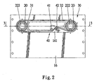
- a metal sheet-feeder for punch according to a first preferred embodiment of the present invention -comprises a platform 10, a link device 30 and a strain device 40.
- the platform 10 comprises two control members 20, and each control member 20 can elastically push against a movable roller 15.
- the link device 30 is disposed between the two control members 20 and is capable of driving one of the two control members 20 to move according to the movement of another one of the two control members 20 so the two control members 20 act synchronously at the movable roller 15.
- the strain device 40 is installed onto the link device 30 to assure the synchronous movement of the link device 30.
- the platform 10 comprises a side panel 11 disposed separately on both sides of the platform 10.
- a fixed roller 12 and a pivotal axle 13 are disposed between the two side panels 11.
- a movable stand 14 is installed onto the pivotal axle 13, and the movable stand 14 uses the pivotal axle 13 as the center of rotation and produces a swinging relation with respect to the side panels 11.
- the movable stand 14 comprises the movable roller 15 being pivotally disposed therein and parallel to the fixed roller 12, such that the movable roller 15 can generate a change to a gap between the swing of the movable roller 15 and the fixed roller 12.
- the movable stand 14 has a spring 141 installed separately on both ends of the top of the movable stand 14.
- the two side panels 11 also install a top panel 16, and an accommodating space 161 is disposed on one side of the top panel 16.
- a through hole 162 is disposed on each of both sides of the accommodating space 161, and the through hole 162 has a thread therein.
- the control member 20 passes into the through hole 162 of the top panel 16 and also couples to the spring 141 of the movable stand 14.
- the control members 20 are pressed by the spring 141 to move the movable stand 14 downward, so that the movable roller 15 pivotally coupled in the movable stand 14 presses on the fixed roller 12.
- the control members 20 pass through the two through holes 162 of the top panel 16 according to this embodiment.
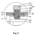
- the control member 20 comprises an adjusting end 21 and a threaded end 22.
- the adjusting end 21 according to this embodiment is a hexagonal adjusting end 21 having a penetrating hole 211 disposed on one side for allowing users to pull the adjusting end 21 by a tool.
- a groove 221 is disposed at the external periphery of the threaded end 22 and is parallel to the axis.
- the threaded end 22 forms a hollow sink hole 222 therein.
- the sink hole 222 can accommodate the spring 141 in contact with the movable stand 14.
- the link device 30 is installed in the accommodating space 161 of the top panel 16 and coupled between the two control members 20.
- the link device 30 comprises two active components 31, a passive component 32 and two bases 33.
- the two active components 31 are coupled to the threaded ends 22 of the two control members 20, respectively.
- the active component 31 has a through hole 311, and a key slot 312 is disposed above the through hole 311.
- a key 313 is installed between the key slot 312 and a groove 221 of the threaded end 22 for driving each other.
- the active component 31. according to this embodiment is a gear
- the passive component 32 according to this embodiment is a synchronous belt installed between the two gears.
- the passive component 32 can effectively drive the active components 31 to rotate.
- the two bases 33 are secured, respectively, to both ends of the accommodating space 161 of the top panel 16 for fixing both active components 31 at appropriate positions.
- the base 33 comprises a through hole 331 having a thread therein for passage of the threaded end 22 of the control member 20.
- the strain device 40 is installed in the accommodating space 161 of the top panel 16 and is in contact with the passive component 32 of the link device 30.
- the strain device 40 comprises a first roller 41 and a second roller 42.
- the first roller 41 is installed onto the internal side of the foregoing synchronous belt and the second roller 42 is installed onto the external side of the synchronous belt.
- the control member 20 is connected with the movable stand 14 by the spring 141, such that the spring 141 of the movable stand 14 can push the movable roller 15 to be in contact with the fixed roller 12 for the material feeding operation.
- the gap between the movable roller 15 and the fixed roller 12 can be adjusted to cope with the change to the thickness of materials. If the movable roller 15 can maintain an even force exerted, on the fixed roller 12, it only needs to rotate one control member 20, with the other control member 20 driven by the link device 30 to produce a synchronous rotation.
- the link device 30 is installed onto the internal side of the top panel 16.
- the link device 30 can produce a synchronous movement for both ends of the movable roller 15.
- the other control member 20 is linked as well.
- the control members 20 utilize the spiral movement of the threaded end 22 for fine tuning a slight axial gain in order to achieve the function of synchronously fine tuning the movable roller 15 to press down.
- one control member 20 drives its adjusting end 21 to rotate, so that the control member 20 drives the gear on the same end to rotate.
- the other control member 20 is driven to produce a synchronous rotation as to produce an effect of synchronously elastically pushing the movable roller 15.
- the spring 141 is compressed to push the movable stand 14.
- the movable stand 14 is pushed synchronously by the springs 141 on both sides, so that both ends of the movable roller 15 produce the same forces and the movable roller 15 will not incline to one side.
- a simple operation can keep an even force at the contact surface between the movable roller 15 and the fixed roller 12, so that the clamped material can be fed smoothly.
- the present invention is a novel useful design.
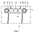
- FIG. 6 Please refer to FIG. 6 for the metal sheet-feeder for punch according to a second preferred embodiment of the present invention.
- the link device 30 collocating with a gear wheel and a chain also gives an excellent effect on the synchronization.
- This embodiment can install a strain device 40 at the chain, so that the chain can press on the two gear wheels to prevent any asynchronous movement caused by the error of the gap and assure the fine-tuned synchronous movement.
- the active component 31 of the link device 30 is a gear
- the passive component 32 comprises a plurality of gears coupled between the active components 31.
- the present invention herein enhances the performance over that of the conventional structure.
Landscapes
- Engineering & Computer Science (AREA)
- Mechanical Engineering (AREA)
- Perforating, Stamping-Out Or Severing By Means Other Than Cutting (AREA)
- Press Drives And Press Lines (AREA)
- Bending Of Plates, Rods, And Pipes (AREA)
Claims (13)
- Metallblech-Zufuhrvorrichtung für eine Stanzmaschine, aufweisend:eine Plattform (10), welche ein erstes Seiten-Paneel (11), ein zweites Seiten-Paneel (11) und ein oberes Paneel (16) umfasst, welches auf dem ersten und dem zweiten Seiten-Paneel (11) angeordnet ist,eine fixierte Walze (12), welche drehbar zwischen das erste und das zweite Seiten-Paneel (11) gekoppelt ist,eine bewegbare Stütze (14) mit einer bewegbaren Walze (15), welche drehbar darin angeordnet und parallel zu der fixierten Walze (12) ist, wobei die bewegbare Walze (15) eine Änderung des Spaltes zwischen der bewegbaren Walze (15) und der fixierten Walze (12) verursachen kann, wobei die bewegbare Walze (15) einen konstanten Druck bezüglich der fixierten Walze (12) aufrecht erhält, um eine gleichmäßige Kraft auf ein Werksstück auszuüben, welches durch die Kontaktflächen der bewegbaren walze (15) und der fixierten Walze (12) eingeklemmt ist, undzwei Steuer-Elemente (20), welche an dem oberen Paneel (16) angeordnet sind und jeweils mittels einer Feder (141) mit der bewegbaren Stütze (14) verbunden sind zum elastischen Drücken der Stütze (14), wobei die durch die Federn (141) aufgebrachte Kraft variiert wird, wenn die Steuer-Elemente (20) angetrieben werden,gekennzeichnet durcheine Verbindungs-Vorrichtung (30), welche die zwei Steuer-Elemente (20) verbindet, zum simultanen Antreiben von einem der Steuer-Elemente (20) gemäß der Bewegung des anderen Steuer-Elements (20), um das Antreiben der zwei Steuer-Elemente (20) zu synchronisieren.
- Metallblech-Zufuhrvorrichtung für eine Stanzmaschine nach Anspruch 1, wobei die bewegbare Stütze (14) schwenkbar zwischen den zwei Seiten-Paneelen (11) angeordnet ist zum Erzeugen einer Schwingbewegung bezüglich der Seiten-Paneele (11).
- Metallblech-Zufuhrvorrichtung für eine Stanzmaschine nach Anspruch 1 oder 2, wobei die Steuer-Elemente (20) mit der bewegbaren Stütze (14) an beiden Enden davon und auf einer Seite der bewegbaren Stütze (14) separat verbunden sind.
- Metallblech-Zufuhrvorrichtung für eine Stanzmaschine nach Anspruch 1, wobei das obere Paneel (16) einen Aufnahme-Raum (161) auf einer Seite davon aufweist zum Installieren der Verbindungs-Vorrichtung (30).
- Metallblech-Zufuhrvorrichtung für eine Stanzmaschine nach Anspruch 4, wobei der Aufnahme-Raum (161) ein Durchgangsloch (162) an jedem der beiden Enden umfasst für den Durchtritt der Steuer-Elemente (20), und wobei das Durchgangsloch (162) ein Gewinde darin aufweist zum gewindemäßigen Aufnehmen des Steuer-Elements (20).
- Metallblech-Zufuhrvorrichtung für eine Stanzmaschine nach Anspruch 1, wobei jedes Steuer-Element (20) ein Einstellende (21), um es dem Benutzer zu ermöglichen, das Steuer-Element (20) zu bedienen, und ein Gewindeende (22) aufweist zum gewindemäßigen Durchtreten durch das obere Paneel (16) und Erzeugen einer spiralförmigen Bewegung.
- Metallblech-Zufuhrvorrichtung für eine Stanzmaschine nach Anspruch 6, wobei das Gewindeende (22) eine Nut (221), welche an dem äußeren Umfang des Gewindeendes (22) angeordnet ist und parallel zu der Achse zum Installieren einer Passfeder (313) verläuft, um den Betrieb der Verbindungs-Vorrichtung (30) anzutreiben, und ein hohles Senkloch (222) zum Aufnehmen der Feder (141) darin aufweist.
- Metallblech-Zufuhrvorrichtung für eine Stanzmaschine nach Anspruch 1, wobei die Verbindungs-Vorrichtung (30) zwei aktive Komponenten (31) und eine passive Komponente (32) aufweist, wobei die aktive Komponente (31) ein Zahnrad ist, und wobei die passive Komponente (32) ein Synchronriemen ist.
- Metallblech-Zufuhrvorrichtung für eine Stanzmaschine nach Anspruch 1, wobei die Verbindungs-Vorrichtung (30) zwei aktive Komponenten (31) und eine passive Komponente (32) aufweist, wobei die aktive Komponente (31) ein Zahnrad ist, und wobei die passive Komponente (32) eine Kette ist.
- Metallblech-Zufuhrvorrichtung für eine Stanzmaschine nach Anspruch 1, wobei die Verbindungs-Vorrichtung (30) zwei aktive Komponenten (31) und eine passive Komponente (32) aufweist, wobei die aktive Komponente (31) ein Zahnrad ist, und wobei die passive Komponente (32) eine Mehrzahl von Zahnrädern aufweist.
- Metallblech-Zufuhrvorrichtung für eine Stanzmaschine nach Anspruch 1, wobei die verbindungs-Vorrichtung (30) zwei aktive Komponenten (31) und eine passive Komponente (32) aufweist, wobei die passive Komponente (32) der Verbindungs-Vorrichtung (30) ferner eine Spannungs-Vorrichtung (40) zum Andrücken der passiven Komponenten (32) gegen die aktive Komponente (31) installiert.
- Metallblech-Zufuhrvorrichtung für eine Stanzmaschine nach Anspruch 1, wobei die Verbindungs-Vorrichtung (30) zwei aktive Komponenten (31), eine passive Komponente (32) und zwei Basiselemente (33) aufweist, wobei die zwei aktiven Komponenten (31) mit den zwei Steuer-Elementen (20) verbunden sind, und wobei die passive Komponente (32) zwischen die zwei aktiven Komponenten (31) gekoppelt ist zum Erzeugen einer synchronen Bewegung.
- Metallblech-Zufuhrvorrichtung für eine Stanzmaschine nach Anspruch 12, wobei die zwei Basiselemente (33) an einer Seite des oberen Paneels (16) befestigt sind zum Fixieren der zwei aktiven Komponenten (31) an zweckmäßigen Positionen.
Priority Applications (3)
| Application Number | Priority Date | Filing Date | Title |
|---|---|---|---|
| AT05026898T ATE371509T1 (de) | 2005-12-08 | 2005-12-08 | Vorrichtung zum vorschieben eines bleches in eine stanzpresse mit einem simultanen antrieb und mit gleichmässiger verteilung des druckes |
| EP05026898A EP1716939B1 (de) | 2005-12-08 | 2005-12-08 | Vorrichtung zum Vorschieben eines Bleches in eine Stanzpresse mit einem simultanen Antrieb und mit gleichmäßiger Verteilung des Druckes |
| DE602005002242T DE602005002242D1 (de) | 2005-12-08 | 2005-12-08 | Vorrichtung zum Vorschieben eines Bleches in eine Stanzpresse mit einem simultanen Antrieb und mit gleichmäßiger Verteilung des Druckes |
Applications Claiming Priority (1)
| Application Number | Priority Date | Filing Date | Title |
|---|---|---|---|
| EP05026898A EP1716939B1 (de) | 2005-12-08 | 2005-12-08 | Vorrichtung zum Vorschieben eines Bleches in eine Stanzpresse mit einem simultanen Antrieb und mit gleichmäßiger Verteilung des Druckes |
Publications (2)
| Publication Number | Publication Date |
|---|---|
| EP1716939A1 EP1716939A1 (de) | 2006-11-02 |
| EP1716939B1 true EP1716939B1 (de) | 2007-08-29 |
Family
ID=36431067
Family Applications (1)
| Application Number | Title | Priority Date | Filing Date |
|---|---|---|---|
| EP05026898A Not-in-force EP1716939B1 (de) | 2005-12-08 | 2005-12-08 | Vorrichtung zum Vorschieben eines Bleches in eine Stanzpresse mit einem simultanen Antrieb und mit gleichmäßiger Verteilung des Druckes |
Country Status (3)
| Country | Link |
|---|---|
| EP (1) | EP1716939B1 (de) |
| AT (1) | ATE371509T1 (de) |
| DE (1) | DE602005002242D1 (de) |
Families Citing this family (2)
| Publication number | Priority date | Publication date | Assignee | Title |
|---|---|---|---|---|
| CN107377812B (zh) * | 2017-08-15 | 2023-07-28 | 蚌埠捷顺机器有限公司 | 一种能够自动上料的卷圆机 |
| CN112122430A (zh) * | 2020-09-14 | 2020-12-25 | 仙居云利电子科技有限公司 | 一种可分拣废料的金属板冲压设备 |
Family Cites Families (6)
| Publication number | Priority date | Publication date | Assignee | Title |
|---|---|---|---|---|
| US2660427A (en) * | 1948-06-26 | 1953-11-24 | Haller John | Feeding device for sheet material |
| US2819072A (en) * | 1955-09-23 | 1958-01-07 | Wittek Rudolph | Automatic roll feed for punch presses |
| CH679134A5 (de) * | 1989-05-03 | 1991-12-31 | Bruderer Ag | |
| JPH04313556A (ja) * | 1990-11-30 | 1992-11-05 | Sankyo Seisakusho:Kk | ロールフィード |
| EP0730920B1 (de) * | 1995-03-03 | 2001-11-21 | SIRI Pressenautomation GmbH | Vorrichtung zum Zwischenlüften einer der Walzen an hochdynamischen Vorschubsystemen mit integrierter Blechdickenmessung |
| DE50114475D1 (de) * | 2001-10-18 | 2008-12-18 | Bruderer Ag | Vorrichtung zum schrittweisen Vorschieben eines bandförmigen Werkstückes |
-
2005
- 2005-12-08 AT AT05026898T patent/ATE371509T1/de not_active IP Right Cessation
- 2005-12-08 DE DE602005002242T patent/DE602005002242D1/de active Active
- 2005-12-08 EP EP05026898A patent/EP1716939B1/de not_active Not-in-force
Also Published As
| Publication number | Publication date |
|---|---|
| DE602005002242D1 (de) | 2007-10-11 |
| ATE371509T1 (de) | 2007-09-15 |
| EP1716939A1 (de) | 2006-11-02 |
Similar Documents
| Publication | Publication Date | Title |
|---|---|---|
| US20050253324A1 (en) | Roller press | |
| CN106183583B (zh) | 一种手动式图案切压器 | |
| EP1716939B1 (de) | Vorrichtung zum Vorschieben eines Bleches in eine Stanzpresse mit einem simultanen Antrieb und mit gleichmäßiger Verteilung des Druckes | |
| US7309222B2 (en) | Apparatus for working pliable material | |
| EP4279251A1 (de) | Synchronriemenspannvorrichtung für 3d-drucker und 3d-drucker | |
| CN215872019U (zh) | 一种fpc弯折贴付治具 | |
| US6991145B1 (en) | Synchronous fine tunable material feeding mechanism | |
| CN210523642U (zh) | 一种压力调节进料装置 | |
| CN205989604U (zh) | 一种手动式图案切压器 | |
| US11766802B2 (en) | Die cutter holding and lifting apparatus | |
| GB2527566A (en) | Hand press | |
| CN110900711A (zh) | 一种平压模切方法和平压模切机 | |
| CN109489652B (zh) | 高精度光纤环绕制辅助排纤装置 | |
| CN2423079Y (zh) | 带锯机锯片导持装置 | |
| CN214354231U (zh) | 便于拆卸光固化3d打印机打印平台的组件 | |
| CN209999685U (zh) | 工件贴膜压紧装置 | |
| KR101527216B1 (ko) | 심압대의 편심 조정 장치 | |
| CN214395665U (zh) | 一种通用性较强的瓦楞纸板生产用单瓦机 | |
| US20240116163A1 (en) | Angle-adjustable power tool | |
| CN218519274U (zh) | 一种可调节式纸箱板压痕装置 | |
| CN220494240U (zh) | 一种布带轮调节盘止动装置 | |
| CN220840437U (zh) | 一种模切机纸板定位结构 | |
| CN213890327U (zh) | 一种稳定性高的手动冲床 | |
| CN216639530U (zh) | 一种皮革加工用皮革压花机 | |
| CN218947513U (zh) | 调带器 |
Legal Events
| Date | Code | Title | Description |
|---|---|---|---|
| PUAI | Public reference made under article 153(3) epc to a published international application that has entered the european phase |
Free format text: ORIGINAL CODE: 0009012 |
|
| 17P | Request for examination filed |
Effective date: 20060829 |
|
| AK | Designated contracting states |
Kind code of ref document: A1 Designated state(s): AT BE BG CH CY CZ DE DK EE ES FI FR GB GR HU IE IS IT LI LT LU LV MC NL PL PT RO SE SI SK TR |
|
| AX | Request for extension of the european patent |
Extension state: AL BA HR MK YU |
|
| GRAP | Despatch of communication of intention to grant a patent |
Free format text: ORIGINAL CODE: EPIDOSNIGR1 |
|
| AKX | Designation fees paid |
Designated state(s): AT BE BG CH CY CZ DE DK EE ES FI FR GB GR HU IE IS IT LI LT LU LV MC NL PL PT RO SE SI SK TR |
|
| GRAS | Grant fee paid |
Free format text: ORIGINAL CODE: EPIDOSNIGR3 |
|
| GRAA | (expected) grant |
Free format text: ORIGINAL CODE: 0009210 |
|
| AK | Designated contracting states |
Kind code of ref document: B1 Designated state(s): AT BE BG CH CY CZ DE DK EE ES FI FR GB GR HU IE IS IT LI LT LU LV MC NL PL PT RO SE SI SK TR |
|
| REG | Reference to a national code |
Ref country code: GB Ref legal event code: FG4D |
|
| RTI1 | Title (correction) |
Free format text: SIMULTANEOUS DRIVE EVEN PRESSURE DISTRIBUTION METAL SHEET-FEEDER FOR PUNCH |
|
| REG | Reference to a national code |
Ref country code: CH Ref legal event code: EP |
|
| REG | Reference to a national code |
Ref country code: IE Ref legal event code: FG4D |
|
| REF | Corresponds to: |
Ref document number: 602005002242 Country of ref document: DE Date of ref document: 20071011 Kind code of ref document: P |
|
| PG25 | Lapsed in a contracting state [announced via postgrant information from national office to epo] |
Ref country code: IS Free format text: LAPSE BECAUSE OF FAILURE TO SUBMIT A TRANSLATION OF THE DESCRIPTION OR TO PAY THE FEE WITHIN THE PRESCRIBED TIME-LIMIT Effective date: 20071229 Ref country code: LT Free format text: LAPSE BECAUSE OF FAILURE TO SUBMIT A TRANSLATION OF THE DESCRIPTION OR TO PAY THE FEE WITHIN THE PRESCRIBED TIME-LIMIT Effective date: 20070829 Ref country code: FI Free format text: LAPSE BECAUSE OF FAILURE TO SUBMIT A TRANSLATION OF THE DESCRIPTION OR TO PAY THE FEE WITHIN THE PRESCRIBED TIME-LIMIT Effective date: 20070829 Ref country code: ES Free format text: LAPSE BECAUSE OF FAILURE TO SUBMIT A TRANSLATION OF THE DESCRIPTION OR TO PAY THE FEE WITHIN THE PRESCRIBED TIME-LIMIT Effective date: 20071210 Ref country code: NL Free format text: LAPSE BECAUSE OF FAILURE TO SUBMIT A TRANSLATION OF THE DESCRIPTION OR TO PAY THE FEE WITHIN THE PRESCRIBED TIME-LIMIT Effective date: 20070829 |
|
| NLV1 | Nl: lapsed or annulled due to failure to fulfill the requirements of art. 29p and 29m of the patents act | ||
| PG25 | Lapsed in a contracting state [announced via postgrant information from national office to epo] |
Ref country code: CH Free format text: LAPSE BECAUSE OF FAILURE TO SUBMIT A TRANSLATION OF THE DESCRIPTION OR TO PAY THE FEE WITHIN THE PRESCRIBED TIME-LIMIT Effective date: 20070829 Ref country code: PL Free format text: LAPSE BECAUSE OF FAILURE TO SUBMIT A TRANSLATION OF THE DESCRIPTION OR TO PAY THE FEE WITHIN THE PRESCRIBED TIME-LIMIT Effective date: 20070829 Ref country code: LI Free format text: LAPSE BECAUSE OF FAILURE TO SUBMIT A TRANSLATION OF THE DESCRIPTION OR TO PAY THE FEE WITHIN THE PRESCRIBED TIME-LIMIT Effective date: 20070829 Ref country code: AT Free format text: LAPSE BECAUSE OF FAILURE TO SUBMIT A TRANSLATION OF THE DESCRIPTION OR TO PAY THE FEE WITHIN THE PRESCRIBED TIME-LIMIT Effective date: 20070829 |
|
| REG | Reference to a national code |
Ref country code: CH Ref legal event code: PL |
|
| PG25 | Lapsed in a contracting state [announced via postgrant information from national office to epo] |
Ref country code: LV Free format text: LAPSE BECAUSE OF FAILURE TO SUBMIT A TRANSLATION OF THE DESCRIPTION OR TO PAY THE FEE WITHIN THE PRESCRIBED TIME-LIMIT Effective date: 20070829 Ref country code: BE Free format text: LAPSE BECAUSE OF FAILURE TO SUBMIT A TRANSLATION OF THE DESCRIPTION OR TO PAY THE FEE WITHIN THE PRESCRIBED TIME-LIMIT Effective date: 20070829 |
|
| EN | Fr: translation not filed | ||
| PG25 | Lapsed in a contracting state [announced via postgrant information from national office to epo] |
Ref country code: DK Free format text: LAPSE BECAUSE OF FAILURE TO SUBMIT A TRANSLATION OF THE DESCRIPTION OR TO PAY THE FEE WITHIN THE PRESCRIBED TIME-LIMIT Effective date: 20070829 Ref country code: GR Free format text: LAPSE BECAUSE OF FAILURE TO SUBMIT A TRANSLATION OF THE DESCRIPTION OR TO PAY THE FEE WITHIN THE PRESCRIBED TIME-LIMIT Effective date: 20071130 |
|
| PG25 | Lapsed in a contracting state [announced via postgrant information from national office to epo] |
Ref country code: SK Free format text: LAPSE BECAUSE OF FAILURE TO SUBMIT A TRANSLATION OF THE DESCRIPTION OR TO PAY THE FEE WITHIN THE PRESCRIBED TIME-LIMIT Effective date: 20070829 Ref country code: CZ Free format text: LAPSE BECAUSE OF FAILURE TO SUBMIT A TRANSLATION OF THE DESCRIPTION OR TO PAY THE FEE WITHIN THE PRESCRIBED TIME-LIMIT Effective date: 20070829 Ref country code: PT Free format text: LAPSE BECAUSE OF FAILURE TO SUBMIT A TRANSLATION OF THE DESCRIPTION OR TO PAY THE FEE WITHIN THE PRESCRIBED TIME-LIMIT Effective date: 20080129 |
|
| PG25 | Lapsed in a contracting state [announced via postgrant information from national office to epo] |
Ref country code: SE Free format text: LAPSE BECAUSE OF FAILURE TO SUBMIT A TRANSLATION OF THE DESCRIPTION OR TO PAY THE FEE WITHIN THE PRESCRIBED TIME-LIMIT Effective date: 20071129 Ref country code: RO Free format text: LAPSE BECAUSE OF FAILURE TO SUBMIT A TRANSLATION OF THE DESCRIPTION OR TO PAY THE FEE WITHIN THE PRESCRIBED TIME-LIMIT Effective date: 20070829 |
|
| PLBE | No opposition filed within time limit |
Free format text: ORIGINAL CODE: 0009261 |
|
| STAA | Information on the status of an ep patent application or granted ep patent |
Free format text: STATUS: NO OPPOSITION FILED WITHIN TIME LIMIT |
|
| PG25 | Lapsed in a contracting state [announced via postgrant information from national office to epo] |
Ref country code: MC Free format text: LAPSE BECAUSE OF NON-PAYMENT OF DUE FEES Effective date: 20071231 Ref country code: DE Free format text: LAPSE BECAUSE OF FAILURE TO SUBMIT A TRANSLATION OF THE DESCRIPTION OR TO PAY THE FEE WITHIN THE PRESCRIBED TIME-LIMIT Effective date: 20071130 |
|
| 26N | No opposition filed |
Effective date: 20080530 |
|
| PG25 | Lapsed in a contracting state [announced via postgrant information from national office to epo] |
Ref country code: IE Free format text: LAPSE BECAUSE OF NON-PAYMENT OF DUE FEES Effective date: 20071210 |
|
| PG25 | Lapsed in a contracting state [announced via postgrant information from national office to epo] |
Ref country code: EE Free format text: LAPSE BECAUSE OF FAILURE TO SUBMIT A TRANSLATION OF THE DESCRIPTION OR TO PAY THE FEE WITHIN THE PRESCRIBED TIME-LIMIT Effective date: 20070829 |
|
| PG25 | Lapsed in a contracting state [announced via postgrant information from national office to epo] |
Ref country code: FR Free format text: LAPSE BECAUSE OF NON-PAYMENT OF DUE FEES Effective date: 20071231 |
|
| PG25 | Lapsed in a contracting state [announced via postgrant information from national office to epo] |
Ref country code: SI Free format text: LAPSE BECAUSE OF FAILURE TO SUBMIT A TRANSLATION OF THE DESCRIPTION OR TO PAY THE FEE WITHIN THE PRESCRIBED TIME-LIMIT Effective date: 20070829 |
|
| PG25 | Lapsed in a contracting state [announced via postgrant information from national office to epo] |
Ref country code: CY Free format text: LAPSE BECAUSE OF FAILURE TO SUBMIT A TRANSLATION OF THE DESCRIPTION OR TO PAY THE FEE WITHIN THE PRESCRIBED TIME-LIMIT Effective date: 20070829 |
|
| PG25 | Lapsed in a contracting state [announced via postgrant information from national office to epo] |
Ref country code: LU Free format text: LAPSE BECAUSE OF NON-PAYMENT OF DUE FEES Effective date: 20071208 Ref country code: BG Free format text: LAPSE BECAUSE OF FAILURE TO SUBMIT A TRANSLATION OF THE DESCRIPTION OR TO PAY THE FEE WITHIN THE PRESCRIBED TIME-LIMIT Effective date: 20071129 |
|
| PG25 | Lapsed in a contracting state [announced via postgrant information from national office to epo] |
Ref country code: HU Free format text: LAPSE BECAUSE OF FAILURE TO SUBMIT A TRANSLATION OF THE DESCRIPTION OR TO PAY THE FEE WITHIN THE PRESCRIBED TIME-LIMIT Effective date: 20080301 |
|
| PGFP | Annual fee paid to national office [announced via postgrant information from national office to epo] |
Ref country code: TR Payment date: 20091125 Year of fee payment: 5 |
|
| PGFP | Annual fee paid to national office [announced via postgrant information from national office to epo] |
Ref country code: GB Payment date: 20091113 Year of fee payment: 5 |
|
| PG25 | Lapsed in a contracting state [announced via postgrant information from national office to epo] |
Ref country code: IT Free format text: LAPSE BECAUSE OF NON-PAYMENT OF DUE FEES Effective date: 20071231 |
|
| GBPC | Gb: european patent ceased through non-payment of renewal fee |
Effective date: 20101208 |
|
| PG25 | Lapsed in a contracting state [announced via postgrant information from national office to epo] |
Ref country code: GB Free format text: LAPSE BECAUSE OF NON-PAYMENT OF DUE FEES Effective date: 20101208 |
|
| PG25 | Lapsed in a contracting state [announced via postgrant information from national office to epo] |
Ref country code: TR Free format text: LAPSE BECAUSE OF NON-PAYMENT OF DUE FEES Effective date: 20101208 |