EP1716916A1 - Disposifif d'agitation d'un liquide et d'injection d'un gaz dans ce liquide adapté à des bassins de faibles profondeurs - Google Patents
Disposifif d'agitation d'un liquide et d'injection d'un gaz dans ce liquide adapté à des bassins de faibles profondeurs Download PDFInfo
- Publication number
- EP1716916A1 EP1716916A1 EP20060300369 EP06300369A EP1716916A1 EP 1716916 A1 EP1716916 A1 EP 1716916A1 EP 20060300369 EP20060300369 EP 20060300369 EP 06300369 A EP06300369 A EP 06300369A EP 1716916 A1 EP1716916 A1 EP 1716916A1
- Authority
- EP
- European Patent Office
- Prior art keywords
- axial flow
- mobile
- gas
- deflector
- liquid
- Prior art date
- Legal status (The legal status is an assumption and is not a legal conclusion. Google has not performed a legal analysis and makes no representation as to the accuracy of the status listed.)
- Granted
Links
Images

Classifications
-
- C—CHEMISTRY; METALLURGY
- C02—TREATMENT OF WATER, WASTE WATER, SEWAGE, OR SLUDGE
- C02F—TREATMENT OF WATER, WASTE WATER, SEWAGE, OR SLUDGE
- C02F3/00—Biological treatment of water, waste water, or sewage
- C02F3/02—Aerobic processes
- C02F3/12—Activated sludge processes
- C02F3/14—Activated sludge processes using surface aeration
- C02F3/16—Activated sludge processes using surface aeration the aerator having a vertical axis
-
- B—PERFORMING OPERATIONS; TRANSPORTING
- B01—PHYSICAL OR CHEMICAL PROCESSES OR APPARATUS IN GENERAL
- B01F—MIXING, e.g. DISSOLVING, EMULSIFYING OR DISPERSING
- B01F23/00—Mixing according to the phases to be mixed, e.g. dispersing or emulsifying
- B01F23/20—Mixing gases with liquids
- B01F23/23—Mixing gases with liquids by introducing gases into liquid media, e.g. for producing aerated liquids
- B01F23/233—Mixing gases with liquids by introducing gases into liquid media, e.g. for producing aerated liquids using driven stirrers with completely immersed stirring elements
- B01F23/2331—Mixing gases with liquids by introducing gases into liquid media, e.g. for producing aerated liquids using driven stirrers with completely immersed stirring elements characterised by the introduction of the gas along the axis of the stirrer or along the stirrer elements
-
- B—PERFORMING OPERATIONS; TRANSPORTING
- B01—PHYSICAL OR CHEMICAL PROCESSES OR APPARATUS IN GENERAL
- B01F—MIXING, e.g. DISSOLVING, EMULSIFYING OR DISPERSING
- B01F27/00—Mixers with rotary stirring devices in fixed receptacles; Kneaders
- B01F27/80—Mixers with rotary stirring devices in fixed receptacles; Kneaders with stirrers rotating about a substantially vertical axis
-
- Y—GENERAL TAGGING OF NEW TECHNOLOGICAL DEVELOPMENTS; GENERAL TAGGING OF CROSS-SECTIONAL TECHNOLOGIES SPANNING OVER SEVERAL SECTIONS OF THE IPC; TECHNICAL SUBJECTS COVERED BY FORMER USPC CROSS-REFERENCE ART COLLECTIONS [XRACs] AND DIGESTS
- Y02—TECHNOLOGIES OR APPLICATIONS FOR MITIGATION OR ADAPTATION AGAINST CLIMATE CHANGE
- Y02W—CLIMATE CHANGE MITIGATION TECHNOLOGIES RELATED TO WASTEWATER TREATMENT OR WASTE MANAGEMENT
- Y02W10/00—Technologies for wastewater treatment
- Y02W10/10—Biological treatment of water, waste water, or sewage
Definitions
- the present invention relates to a device for stirring a liquid in a reactor and injecting a gas into the liquid.
- the document EP-A1-0 995 485 discloses a device for stirring a liquid in a reactor, or basin, and injecting a gas into the liquid.
- This device comprises a drive motor of a vertical shaft disposed above the reactor.
- the motor shaft carries and drives at its lower end a propeller immersed in the liquid; it also carries and drives a self-suction turbine placed between the surface of the liquid and the propeller.
- the self-suction turbine is connected to a source of gas, generally an oxygenated gas, so that when it is driven by the motor shaft, it sucks both gas and liquid in which it is immersed thus forming a gas-liquid dispersion.
- the gas-liquid dispersion generated by the self-suction turbine is directed towards the propeller by means of an annular baffle box which envelops the self-suction turbine.
- the pumping power of the propeller generates downward currents of liquid and gas up to more than 7 meters deep. Also, when the bottom of the pond is located 7 meters or less, the current impacts the bottom. It does not matter if the walls and the bottom of the reactor are concrete, or if the depth exceeds 3 meters. On the contrary, it makes it possible to set in motion the sludge that tends to accumulate at the bottom of the reactor.
- some reactors have walls and a bottom made of geotextile membranes or clay, which are very sensitive to abrasion. In general, these basins are very shallow (1.5 to 3 meters). The impact of a powerful flow erodes and digs such funds, up to jeopardize the tightness of the reactor. In addition, the movement of large quantities of clay disturbs the settling of sludge downstream of the aeration basin.
- the object of the present invention is to propose a device for agitating a liquid in a reactor and for injecting a gas into this liquid, in which a powerful axial flow is created which can be used in ponds. shallow depths or in basins with friable walls.
- reactor means "basin” natural and “reservoir” walls more or less close and more or less closed sky.
- the stirring device comprises a drive device, for example a motor, arranged above the surface of the liquid, provided with a rotary output shaft extending vertically and partially immersed in the liquid .
- the shaft carries at its lower end an axial flow mobile, which may be a helix or a screw, immersed in the liquid, and generally directing the liquid to the bottom of the basin.
- the device also comprises a means for introducing the gas above the mobile axial flow and in the liquid so that the gas and the liquid are driven by the axial flow mobile and a gas-liquid dispersion is created.
- the device comprises a deflector placed above the mobile axial flow of such shape that it prevents the rise of the gas-liquid dispersion.
- This shape can direct the axial flow down the basin and / or can serve as a gas collector preventing it from escaping to the surface of the basin.
- the essential characteristic of the invention is that an additional deflector is placed below the axial flow mobile and is of a shape such that it transforms the axial flow created by the mobile radial flow.
- the deflector placed below the axial flow mobile can be a plate, generally circular. Preferably, this plate is centered on the output shaft. It may be advantageous to place this deflector placed below the mobile axial flow at the greatest distance possible from said mobile so as to make the best use of the depth available under the stirring device.
- the surface of the deflector placed below the mobile axial flow is increased depending on the distance between the deflector and the mobile axial flow. By way of indication, for a baffle-moving distance with an axial flow of less than 200 mm, it suffices that the surface of the deflector is at least of the order of the surface projected on it by the axial flow mobile.
- the surface of the baffle may also be extended to the surface projected on it by the overall agitation device.
- a deflection cone or prism can be centered on the plateau.
- the angle of the cone or prism can be optimized depending on the distance between the deflector placed below the axial flow mobile and said axial flow mobile.
- the deflector placed below the axial flow mobile can be fixed on the output shaft of the drive device. During operation of the device, the deflector placed below the mobile axial flow is then also driven by the engine.
- This implementation has the advantage of allowing to quickly modify a device of the prior art to adapt it to basins of shallow depths: it suffices to add a deflector on the drive shaft.
- the diverging profile of the surface portions is advantageously calculated to provide a minimum passage section under the axial flow mobile, said section widening downwards.
- This minimum section can represent 1.5 to 3 times the projected section of the axial flow mobile.
- the shape of the divergent profile makes it possible to force the flow of the gas / liquid dispersion to rush between the surface portions and the central axis of the mobile. It is preferable that the winding diameter of the surface portions is not less than the diameter of the axial flow mobile.
- the deflector therefore consists of two parts: the central plate and the surface portions angularly distributed around the plate.
- the central plateau is preferably circular. It can be fixed on the output shaft of the drive device as for the first variant.
- a deflection cone may advantageously replace the central plate.
- At a distance from the central plate or the cone are surface portions angularly distributed around the plate.
- these surface portions having an evolutive profile diverge towards the outside and towards the bottom of the reactor: thus, in cross-section along a plane passing through the vertical output shaft, these surfaces have a profile which away to the outside and the bottom of the reactor. This profile is generally curved in order to generate a Coanda-like effect to any fast flow circulating tangentially to the entry of the profile.
- the axial flow from the mobile axial flow is redirected by the central plate or the cone tangentially to the profile described by the surfaces previously described: it is pressed against the surface portions angularly distributed around the central plateau or cone.
- the Coanda effect thus obtained maintains the flow of the gas / liquid dispersion plated beneath the surface portions.
- This flow is released at the end of the profile at the angle defined by it; preferably, the end of the profile is horizontal to obtain a radial flow directed towards the vertical walls of the reactor.
- This second variant makes it possible to limit the pressure drop when the axial flow comes into contact with the baffle and to standardize the flow.
- the speed of the liquid redirected by the deflector is very fast and the high flow; therefore, the operation of the axial flow mobile is not impeded by the added deflector.
- the conditions for transferring the gas into the liquid remain optimal.
- the radial ejection of the flow can be controlled with respect to the vertical. It is thus possible to better distribute the flow in the basin.
- FIG. 1 makes it possible to characterize a device according to the present invention.
- the device comprises a drive device 1, for example a motor, disposed above the surface of the liquid, provided with a rotary output shaft 2 extending vertically and partially immersed in the liquid.
- the shaft 2 carries at its lower end a mobile axial flow 4, a helix, immersed in the liquid.
- the shaft 2 also carries, arranged between the helix 4 and the surface of the liquid, a self-suction turbine 3 which is consequently immersed in the reactor and is driven by the output shaft 2 at the same speed as the propeller 4.
- the output shaft 2 is coaxially wrapped by a cylinder 7 connected at its upper end to the drive device 1, with the interposition of a sealing device, and whose lower end 7a opens into the turbine 3 coaxially with the shaft 2.
- a cylinder 7 connected at its upper end to the drive device 1, with the interposition of a sealing device, and whose lower end 7a opens into the turbine 3 coaxially with the shaft 2.
- an opening 8 for injecting a gas into the annular gap 9 defined by the shaft 2 and the cylinder 7.
- the injection system gas in the orifice 8 is not shown.
- the self-suction turbine 3 consists of two disks 10, 11 placed horizontally, and a set of radial vanes, placed between the disks 10, 11 and fixed thereto.
- a first deflector 5 is placed above the turbine 3 and the axial flow mobile 4.
- a second deflector 6 is placed on the shaft 2 below the axial flow helix 4.
- the device of Figure 1 also comprises counter-blades 14 for directing the different streams to maximize
- FIG. 2 illustrates a deflector 6 intended to be placed beneath the axial flow mobile in the form of a plate, centered on the output shaft 2, and at the center of which is placed a deflection cone 13.
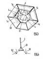
- FIG. 3 illustrates a device according to the invention seen from below.
- This device is equipped with a deflector 61, 62 placed below the mobile axial flow 4 of which three blades can be identified in the drawing.
- This deflector consists of a central circular plate 61, and surface portions 62 angularly distributed around the central circular plate 61 and having an evolutive profile diverging outwardly. This particular shape causes a Coanda-like effect on any rushing flow tangentially to the profile described by the surface potions 62.
- These surface portions 62 are attached to the counter-blades 14 of the stirring device.
- FIG. 4 is a cross-section along the axis xx 'of the deflector of FIG. 3: it is possible to observe the deflector cone 61 centered on the central plate and the profile making it possible to generate the Coanda effect of the surface portions 62 angularly distributed around of the central plateau.
- the arrows represent the flow current along the central plate or deflector cone (61) and portions angularly distributed around the central plate or cone.
- the axial flow of the axial flow mobile is deflected and the impact of the axial flow on the bottom of the basin is avoided.
Landscapes
- Life Sciences & Earth Sciences (AREA)
- Chemical & Material Sciences (AREA)
- Engineering & Computer Science (AREA)
- Biodiversity & Conservation Biology (AREA)
- Microbiology (AREA)
- Hydrology & Water Resources (AREA)
- Chemical Kinetics & Catalysis (AREA)
- Environmental & Geological Engineering (AREA)
- Water Supply & Treatment (AREA)
- Organic Chemistry (AREA)
- Mixers Of The Rotary Stirring Type (AREA)
- Physical Or Chemical Processes And Apparatus (AREA)
- Filling Or Discharging Of Gas Storage Vessels (AREA)
Abstract
- un dispositif d'entraînement (1) disposé au-dessus du réacteur, pourvu d'un arbre de sortie (2) vertical équipé à son extrémité inférieure d'au moins un mobile à flux axial (4) immergé dans le liquide,
- un moyen d'introduction du gaz (3 et 7) au-dessus du mobile à flux axial (4),
- un déflecteur (5) placé au-dessus du mobile à flux axial (4) empêchant la remontée de la dispersion gaz-liquide,
- un déflecteur (6) placé au-dessous du mobile à flux axial (4) transformant le flux axial dudit mobile à flux axial en flux radial. Ce dispositif peut être utilisé dans les bassins de faibles profondeurs.
Description
- La présente invention concerne un dispositif d'agitation d'un liquide dans un réacteur et d'injection d'un gaz dans ce liquide.
- Le document
EP-A1-0 995 485 décrit un dispositif d'agitation d'un liquide dans un réacteur, ou bassin, et d'injection d'un gaz dans ce liquide. Ce dispositif comprend un moteur d'entraînement d'un arbre vertical disposé au-dessus du réacteur. L'arbre du moteur porte et entraîne à son extrémité inférieure une hélice immergée dans le liquide ; il porte et entraîne également une turbine auto-aspirante placée entre la surface du liquide et l'hélice. La turbine auto-aspirante est connectée à une source de gaz, généralement un gaz oxygéné, de manière à ce que lorsqu'elle est entraînée par l'arbre du moteur, elle aspire à la fois du gaz et du liquide dans lequel elle est immergée, formant ainsi une dispersion gaz-liquide. La dispersion gaz-liquide générée par la turbine auto-aspirante est dirigée vers l'hélice à l'aide d'un caisson annulaire formant déflecteur qui enveloppe la turbine auto-aspirante. - Dans la pratique, la puissance de pompage de l'hélice engendre des courants descendants de liquide et de gaz pouvant atteindre plus de 7 mètres de profondeur. Aussi, lorsque le fond du bassin est situé à 7 mètres et moins, le courant impacte le fond. Cela n'a pas d'importance si les parois et le fond du réacteur sont en béton, ou si la profondeur excède 3 mètres. Au contraire, cela permet de mettre en mouvement les boues qui tendent à s'accumuler au fond du réacteur. Par contre, certains réacteurs possèdent des parois et un fond en membranes géotextiles ou en argile, qui sont très sensibles à l'abrasion. En général, ces bassins sont très peu profonds (1,5 à 3 mètres). L'impact d'un flux puissant érode et creuse de tels fonds, jusqu'à mettre en péril l'étanchéité du réacteur. De plus, la mise en mouvement de fortes quantités d'argile perturbe la décantation des boues en aval du bassin d'aération.
- Le but de la présente invention est de proposer un dispositif d'agitation d'un liquide dans un réacteur et d'injection d'un gaz dans ce liquide, dans lequel un flux axial puissant est créé, pouvant être mis en oeuvre dans des bassins de faibles profondeurs ou dans des bassins aux parois friables.
- Dans ce but, l'invention concerne un dispositif d'agitation d'un liquide dans un réacteur et d'injection d'un gaz dans ledit liquide pour former une dispersion gaz-liquide, comprenant :
- un dispositif d'entraînement disposé au-dessus du réacteur, pourvu d'un arbre de sortie vertical équipé à son extrémité inférieure d'au moins un mobile à flux axial immergé dans le liquide,
- un moyen d'introduction du gaz au-dessus du mobile à flux axial,
- un déflecteur placé au-dessus du mobile à flux axial empêchant la remontée de la dispersion gaz-liquide,
- D'autres caractéristiques et avantages de l'invention apparaîtront à la lecture de la description qui va suivre. Des formes et des modes de réalisation de l'invention sont donnés à titre d'exemples non limitatifs, illustrés par les dessins joints dans lesquels :
- la figure 1 est une vue d'un dispositif selon l'invention,
- la figure 2 est une vue du déflecteur placé au-dessous du mobile à flux axial et transformant le flux axial dudit mobile en flux radial utilisable dans le dispositif selon l'invention,
- la figure 3 est une vue du dessous d'un dispositif selon l'invention,
- la figure 4 est une coupe transversale du déflecteur mise en oeuvre sur la figure 3.
- Dans ce qui suit, le terme « réacteur » signifie « bassin » naturel ainsi que « réservoir » à parois plus ou moins proches et à ciel plus ou moins fermé.
- L'invention concerne donc un dispositif d'agitation d'un liquide dans un réacteur et d'injection d'un gaz dans ledit liquide pour former une dispersion gaz-liquide, comprenant :
- un dispositif d'entraînement disposé au-dessus du réacteur, pourvu d'un arbre de sortie vertical équipé à son extrémité inférieure d'au moins un mobile à flux axial immergé dans le liquide,
- un moyen d'introduction du gaz au-dessus du mobile à flux axial,
- un déflecteur placé au-dessus du mobile à flux axial empêchant la remontée de la dispersion gaz-liquide,
- Selon l'invention, le dispositif d'agitation comprend un dispositif d'entraînement, par exemple un moteur, disposé au-dessus de la surface du liquide, pourvu d'un arbre rotatif de sortie s'étendant verticalement et partiellement immergé dans le liquide. L'arbre porte à son extrémité inférieure un mobile à flux axial, qui peut être une hélice ou une vis, immergé dans le liquide, et dirigeant généralement le liquide vers le bas du bassin. Le dispositif comprend également un moyen d'introduction du gaz au-dessus du mobile à flux axial et dans le liquide de manière à ce que le gaz et le liquide soient entraînés par le mobile à flux axial et qu'une dispersion gaz-liquide soit créée. Le dispositif comprend enfin un déflecteur placé au-dessus du mobile à flux axial de forme telle qu'il empêche la remontée de la dispersion gaz-liquide. Cette forme peut permettre de diriger le flux axial vers le bas du bassin et/ou peut servir de collecteur de gaz empêchant ce dernier de s'échapper à la surface du bassin. La caractéristique essentielle de l'invention tient à ce qu'un déflecteur supplémentaire est placé au-dessous du mobile à flux axial et est d'une forme telle qu'il transforme le flux axial créé par le mobile en flux radial.
- Selon une première variante du dispositif selon l'invention, le déflecteur placé au-dessous du mobile à flux axial peut être un plateau, généralement circulaire. De préférence, ce plateau est centré sur l'arbre de sortie. Il peut être avantageux de placer ce déflecteur placé au-dessous du mobile à flux axial à la plus grande distance possible dudit mobile de manière à exploiter au mieux la profondeur disponible sous le dispositif d'agitation. Généralement, la surface du déflecteur placé au-dessous du mobile à flux axial est augmentée en fonction de la distance entre ce déflecteur et ce mobile à flux axial. A titre indicatif, pour une distance déflecteur - mobile à flux axial inférieure à 200 mm, il suffit que la surface du déflecteur soit au moins de l'ordre de la surface projetée sur lui par le mobile à flux axial. La surface du déflecteur peut également être étendue à la surface projetée sur lui par le dispositif d'agitation global.
- Un cône de déflection ou un prisme peut être centré sur le plateau. L'angle du cône ou du prisme peut être optimisé en fonction de la distance entre le déflecteur placé au-dessous du mobile à flux axial et ledit mobile à flux axial.
- D'un point de vue pratique, le déflecteur placé au-dessous du mobile à flux axial peut être fixé sur l'arbre de sortie du dispositif d'entraînement. Lors du fonctionnement du dispositif, le déflecteur placé au-dessous du mobile à flux axial est alors également entraîné par le moteur. Cette mise en oeuvre présente l'avantage de permettre de modifier rapidement un dispositif de l'art antérieur pour l'adapter à des bassins de faibles profondeurs : il suffit de rajouter un déflecteur sur l'arbre d'entraînement.
- Selon une deuxième variante de l'invention, le déflecteur placé au-dessous du mobile à flux axial est constitué :
- d'un plateau central, et
- de portions de surface angulairement réparties autour du plateau central et présentant un profil évolutif divergent vers l'extérieur et vers le fond du réacteur.
- Le profil divergent des portions de surfaces est avantageusement calculé de façon à offrir une section de passage minimale sous le mobile à flux axial, ladite section allant s'élargissant vers le bas. Cette section minimale peut représenter 1,5 à 3 fois la section projetée du mobile à flux axial. La forme du profil divergent permet de forcer le flux de la dispersion gaz/liquide à s'engouffrer entre les portions de surface et l'axe central du mobile. Il est préférable que le diamètre d'enroulement des portions de surfaces ne soit pas inférieur au diamètre du mobile à flux axial.
- Selon cette variante, le déflecteur est donc constitué de deux parties : le plateau central et les portions de surface angulairement réparties autour du plateau. Le plateau central est de préférence circulaire. Il peut être fixé sur l'arbre de sortie du dispositif d'entraînement comme pour la première variante. Un cône de déflection peut avantageusement remplacer le plateau central. A distance du plateau central ou du cône se trouvent des portions de surface angulairement réparties autour du plateau. Selon l'invention, ces portions de surface présentant un profil évolutif divergent vers l'extérieur et vers le fond du réacteur : ainsi, en coupe transversale selon un plan passant par l'arbre de sortie vertical, ces surfaces présentent un profil qui s'écarte vers l'extérieur et le fond du réacteur. Ce profil est généralement courbé afin de générer un effet de type Coanda à tout écoulement rapide circulant tangentiellement à l'entrée du profil. Par la combinaison de ces deux parties du mobile, le flux axial provenant du mobile à flux axial est redirigé par le plateau central ou le cône tangentiellement au profil décrit par les surfaces précédemment décrites: il est plaqué contre les portions de surface angulairement réparties autour du plateau central ou du cône. L'effet Coanda ainsi obtenu maintient l'écoulement de la dispersion gaz/liquide plaqué sous les portions de surface. Cet écoulement est libéré en extrémité du profil suivant l'angle défini par celui-ci ; de préférence, l'extrémité du profil est à l'horizontale pour obtenir un flux radial dirigé vers les parois verticales du réacteur.
- Cette deuxième variante permet de limiter la perte de charge lorsque le flux axial rentre en contact avec le déflecteur et d'uniformiser l'écoulement. La vitesse du liquide redirigé par le déflecteur est très rapide et le débit élevé ; par conséquent, le fonctionnement du mobile à flux axial n'est pas entravé par le déflecteur ajouté. Les conditions de transfert du gaz dans le liquide restent optimales.
- Selon l'angle en extrémité du profil permettant de générer l'effet Coanda, l'éjection radiale du flux peut être contrôlée par rapport à la verticale. Il est ainsi possible de mieux répartir le flux dans le bassin.
- Selon le mode préféré de l'invention, le dispositif présente un moyen d'introduction du gaz au-dessus du mobile à flux axial particulier, qui est constitué :
- d'une turbine auto-aspirante immergée dans le réacteur, placée au-dessus du mobile à flux axial et pouvant être entraînée par l'arbre de sortie, et
- d'un cylindre enveloppant coaxialement l'arbre de sortie, dont l'extrémité inférieure débouche dans la turbine et dont l'extrémité supérieure est liée de manière étanche au dispositif d'entraînement et est percée d'une ouverture d'injection d'un gaz dans un intervalle annulaire délimité par l'arbre et le cylindre,
- La figure 1 permet de caractériser un dispositif selon la présente invention. Le dispositif comprend un dispositif d'entraînement 1, par exemple un moteur, disposé au-dessus de la surface du liquide, pourvu d'un arbre rotatif de sortie 2 s'étendant verticalement et partiellement immergé dans le liquide. L'arbre 2 porte à son extrémité inférieure un mobile à flux axial 4, une hélice, immergé dans le liquide. L'arbre 2 porte également, disposée entre l'hélice 4 et la surface du liquide, une turbine auto-aspirante 3 qui est par conséquent immergée dans le réacteur et est entraînée par l'arbre de sortie 2 à la même vitesse que l'hélice 4. L'arbre de sortie 2 est enveloppé coaxialement par un cylindre 7 lié à son extrémité supérieure au dispositif d'entraînement 1, avec interposition d'un dispositif d'étanchéité, et dont l'extrémité inférieure 7a débouche dans la turbine 3 coaxialement à l'arbre 2. Dans l'extrémité supérieure du cylindre 7 est percée une ouverture 8 d'injection d'un gaz dans l'intervalle annulaire 9 délimité par l'arbre 2 et par le cylindre 7. Le système d'injection de gaz dans l'orifice 8 n'est pas représenté. La turbine auto-aspirante 3 est constituée de deux disques 10, 11 placés horizontalement, et d'un ensemble d'aubes radiales, placées entre les disques 10, 11 et fixées à ceux-ci. Un premier déflecteur 5 est placé au-dessus de la turbine 3 et du mobile à flux axial 4. Un second déflecteur 6 est placé sur l'arbre 2 au-dessous de l'hélice à flux axial 4. Le dispositif de la figure 1 comprend également des contre-pales 14 permettant de diriger les différents flux afin de maximiser les performances en terme de transfert et d'agitation.
- La figure 2 illustre un déflecteur 6 destiné à être placé au-dessous du mobile à flux axial présentant la forme d'un plateau, centré sur l'arbre de sortie 2, et au centre duquel est placé un cône de déflection 13.
- La figure 3 illustre un dispositif selon l'invention vu de dessous. Ce dispositif est équipé d'un déflecteur 61, 62 placé au-dessous du mobile à flux axial 4 dont trois pales peuvent être identifiées sur le dessin. Ce déflecteur est constitué d'un plateau circulaire central 61, et de portions de surface 62 angulairement réparties autour du plateau circulaire central 61 et présentant un profil évolutif divergent vers l'extérieur. Cette forme particulière provoque un effet de type Coanda à tout écoulement s'engouffrant tangentiellement au profil décrit par les potions de surface 62. Ces portions de surface 62 sont fixées aux contre-pales 14 du dispositif d'agitation.
- La figure 4 est une coupe transversale selon l'axe xx' du déflecteur de la figure 3 : on peut observer le cône déflecteur 61 centré sur le plateau central et le profil permettant de générer l'effet Coanda des portions de surface 62 angulairement réparties autour du plateau central. Les flèches représentent le courant du flux le long du plateau central ou cône déflecteur (61) et des portions angulairement réparties autour du plateau ou cône central.
- Par mise en oeuvre d'un dispositif tel que précédemment décrit, le flux axial du mobile à flux axial est dévié et l'impact du flux axial sur le fond du bassin est évité.
Claims (12)
- Dispositif d'agitation d'un liquide dans un réacteur et d'injection d'un gaz dans ledit liquide pour former une dispersion gaz-liquide, comprenant :- un dispositif d'entraînement (1) disposé au-dessus du réacteur, pourvu d'un arbre de sortie (2) vertical équipé à son extrémité inférieure d'au moins un mobile à flux axial (4) immergé dans le liquide,- un moyen d'introduction du gaz (3 et 7) au-dessus du mobile à flux axial (4),- un déflecteur (5) placé au-dessus du mobile à flux axial (4) empêchant la remontée de la dispersion gaz-liquide,caractérisé en ce qu'il comprend un déflecteur (6) placé au-dessous du mobile à flux axial (4) transformant le flux axial dudit mobile en flux radial.
- Dispositif selon la revendication 1, caractérisé en ce que le déflecteur (6) placé au-dessous du mobile à flux axial (4) est un plateau.
- Dispositif selon la revendication 2, caractérisé en ce que le plateau est centré sur l'arbre de sortie (2).
- Dispositif selon la revendication 2 ou 3, caractérisé en ce qu'un cône de déflection (14) est centré sur le plateau.
- Dispositif selon la revendication 2 ou 3, caractérisé en ce qu'un prisme de déflection est centré sur le plateau.
- Dispositif selon l'une des revendications précédentes, caractérisé en ce que la surface du déflecteur (6) placé au-dessous du mobile à flux axial (4) est étendue à la surface projetée sur lui par le dispositif d'agitation.
- Dispositif selon l'une des revendications précédentes, caractérisé en ce que le déflecteur (6) placé au-dessous du mobile à flux axial (4) est fixé sur l'arbre de sortie (2) du dispositif d'entraînement (1).
- Dispositif selon la revendication 1, caractérisé en ce que le déflecteur (6) placé au-dessous du mobile à flux axial est constitué :- d'un plateau central (61), et- de portions de surface (62) angulairement réparties autour du plateau circulaire central (61) et présentant un profil évolutif divergent vers l'extérieur et vers le fond du réacteur.
- Dispositif selon la revendication 8, caractérisé en ce que le profil évolutif divergent des portions de surface (62) est de nature à provoquer un effet Coanda sur tout écoulement s'engouffrant tangentiellement dans la section décrite par le profil évolutif divergent.
- Dispositif selon la revendication 8 ou 9, caractérisé en ce que le plateau central (61) est fixé sur l'arbre de sortie du dispositif d'entraînement (2).
- Dispositif selon l'une des revendications 8 à 10, caractérisé en ce qu'un cône de déflection est centré sur le plateau central (61).
- Dispositif selon l'une des revendications précédentes, caractérisé en ce que :- le moyen d'introduction du gaz au-dessus du mobile à flux axial est constitué :. d'une turbine auto-aspirante (3) immergée dans le réacteur, placée au-dessus du mobile à flux axial (4) et pouvant être entraînée par l'arbre de sortie (2), et. d'un cylindre (7) enveloppant coaxialement l'arbre de sortie (2), dont l'extrémité inférieure (7a) débouche dans la turbine (3) et dont l'extrémité supérieure est liée de manière étanche au dispositif d'entraînement (1) et est percée d'une ouverture (8) d'injection d'un gaz dans un intervalle annulaire (9) délimité par l'arbre (2) et le cylindre (7),- la turbine (3) étant constituée de deux disques superposés (10, 11) et d'un ensemble d'aubes radiales disposées entre les disques et fixées à ceux-ci, le disque supérieur (10) étant percé d'un trou central (12) dans lequel pénètre l'extrémité inférieure (7a) du cylindre (7) qui délimite avec le bord dudit trou un espace au moins partiellement annulaire par lequel du liquide est aspiré dans la turbine (3).
Applications Claiming Priority (1)
| Application Number | Priority Date | Filing Date | Title |
|---|---|---|---|
| FR0550985A FR2884442B1 (fr) | 2005-04-19 | 2005-04-19 | Dispositif d'agitation d'un liquide et d'injection d'un gaz dans ce liquide adapte a des bassins de faibles profondeurs |
Publications (2)
| Publication Number | Publication Date |
|---|---|
| EP1716916A1 true EP1716916A1 (fr) | 2006-11-02 |
| EP1716916B1 EP1716916B1 (fr) | 2007-12-12 |
Family
ID=35385670
Family Applications (1)
| Application Number | Title | Priority Date | Filing Date |
|---|---|---|---|
| EP20060300369 Expired - Lifetime EP1716916B1 (fr) | 2005-04-19 | 2006-04-13 | Dispositif d'agitation d'un liquide et d'injection d'un gaz dans ce liquide adapté à des bassins de faibles profondeurs |
Country Status (7)
| Country | Link |
|---|---|
| US (3) | US20060255482A1 (fr) |
| EP (1) | EP1716916B1 (fr) |
| AT (1) | ATE380579T1 (fr) |
| CA (1) | CA2542729C (fr) |
| DE (1) | DE602006000311T2 (fr) |
| ES (1) | ES2297819T3 (fr) |
| FR (1) | FR2884442B1 (fr) |
Families Citing this family (8)
| Publication number | Priority date | Publication date | Assignee | Title |
|---|---|---|---|---|
| FR2884442B1 (fr) * | 2005-04-19 | 2007-05-25 | Air Liquide | Dispositif d'agitation d'un liquide et d'injection d'un gaz dans ce liquide adapte a des bassins de faibles profondeurs |
| US8387957B2 (en) * | 2009-01-29 | 2013-03-05 | Aqua-Aerobic Systems, Inc. | Downflow mixers with gas injection devices and/or baffles |
| FR2975606B1 (fr) * | 2011-05-25 | 2013-05-31 | Air Liquide | Equipement pour l'injection d'un gaz dans un bassin d'epuration |
| FI124934B (fi) * | 2013-01-30 | 2015-03-31 | Outotec Oyj | Sekoitussäiliöreaktori |
| CN105636913B (zh) * | 2013-07-18 | 2018-02-09 | 张顺远 | 曝气装置 |
| US10683221B2 (en) | 2017-12-14 | 2020-06-16 | L'Air Liquide, Société Anonyme pour l'Etude et l'Exploitation des Procédés Georges Claude | Gas injection and recycling apparatus and methods |
| US11352276B2 (en) * | 2020-05-01 | 2022-06-07 | Aqua-Aerobic Systems, Inc. | Flow straightening vane for aerator |
| CN114751532B (zh) * | 2022-03-18 | 2022-12-02 | 华夏中然生态科技集团有限公司 | 一种污水处理用增氧型曝气设备及其方法 |
Citations (4)
| Publication number | Priority date | Publication date | Assignee | Title |
|---|---|---|---|---|
| CH294349A (fr) * | 1951-08-13 | 1953-11-15 | Pista Sa | Installation pour le traitement d'un liquide. |
| GB1221022A (en) * | 1967-12-08 | 1971-02-03 | Jones & Attwood Ltd | Treatment of a liquid by means of a gaseous fluid |
| EP0995485A1 (fr) * | 1998-10-09 | 2000-04-26 | L'air Liquide, Societe Anonyme Pour L'etude Et L'exploitation Des Procedes Georges Claude | Dispositif d'agitation d'un liquide dans un réacteur et d'injection d'un gaz dans ce liquide |
| US6109449A (en) * | 1998-11-04 | 2000-08-29 | General Signal Corporation | Mixing system for separation of materials by flotation |
Family Cites Families (13)
| Publication number | Priority date | Publication date | Assignee | Title |
|---|---|---|---|---|
| US4290885A (en) * | 1977-12-22 | 1981-09-22 | Dochan Kwak | Aeration device |
| US4265739A (en) * | 1979-01-23 | 1981-05-05 | Dalton Robert W | Flotation machines and components thereof |
| DE2938668C2 (de) * | 1979-09-25 | 1982-06-24 | Bergwerksverband Gmbh, 4300 Essen | Mechanischer Entschäumer für Gas-/Flüssigkeitsreaktoren |
| US4818404A (en) * | 1987-07-08 | 1989-04-04 | Tri-Bio, Inc. | Submerged biological wastewater treatment system |
| US6460830B1 (en) * | 1997-01-08 | 2002-10-08 | Carbofil International | Device for stirring and aerating a liquid and eliminating foam in a tank for treating said liquid |
| US6142458A (en) * | 1998-10-29 | 2000-11-07 | General Signal Corporation | Mixing system for dispersion of gas into liquid media |
| FR2848472B1 (fr) * | 2002-12-12 | 2005-02-18 | Air Liquide | Dispositif d'agitation d'un liquide et d'injection d'un gaz dans ce liquide a engorgement limite |
| FR2868332B1 (fr) * | 2004-03-31 | 2006-05-26 | Air Liquide Electronics Sys | Appareil de traitement d'effluents gazeux |
| US8146894B2 (en) * | 2004-06-21 | 2012-04-03 | Hills Blair H | Apparatus for mixing gasses and liquids |
| FR2884442B1 (fr) * | 2005-04-19 | 2007-05-25 | Air Liquide | Dispositif d'agitation d'un liquide et d'injection d'un gaz dans ce liquide adapte a des bassins de faibles profondeurs |
| PL2175972T3 (pl) * | 2007-08-09 | 2012-10-31 | Invent Umwelt & Verfahrenstech | Urządzenie do mieszania osadów aktywowanych |
| WO2009103087A2 (fr) * | 2008-02-15 | 2009-08-20 | Water Pod, Inc. | Système et procédé d’aération de déchets liquides |
| US8387957B2 (en) * | 2009-01-29 | 2013-03-05 | Aqua-Aerobic Systems, Inc. | Downflow mixers with gas injection devices and/or baffles |
-
2005
- 2005-04-19 FR FR0550985A patent/FR2884442B1/fr not_active Expired - Fee Related
-
2006
- 2006-04-11 CA CA 2542729 patent/CA2542729C/fr not_active Expired - Lifetime
- 2006-04-13 EP EP20060300369 patent/EP1716916B1/fr not_active Expired - Lifetime
- 2006-04-13 AT AT06300369T patent/ATE380579T1/de not_active IP Right Cessation
- 2006-04-13 DE DE200660000311 patent/DE602006000311T2/de not_active Expired - Lifetime
- 2006-04-13 ES ES06300369T patent/ES2297819T3/es not_active Expired - Lifetime
- 2006-04-19 US US11/407,778 patent/US20060255482A1/en not_active Abandoned
-
2012
- 2012-02-21 US US13/401,421 patent/US8308143B2/en not_active Expired - Fee Related
- 2012-10-30 US US13/664,254 patent/US20130127073A1/en not_active Abandoned
Patent Citations (4)
| Publication number | Priority date | Publication date | Assignee | Title |
|---|---|---|---|---|
| CH294349A (fr) * | 1951-08-13 | 1953-11-15 | Pista Sa | Installation pour le traitement d'un liquide. |
| GB1221022A (en) * | 1967-12-08 | 1971-02-03 | Jones & Attwood Ltd | Treatment of a liquid by means of a gaseous fluid |
| EP0995485A1 (fr) * | 1998-10-09 | 2000-04-26 | L'air Liquide, Societe Anonyme Pour L'etude Et L'exploitation Des Procedes Georges Claude | Dispositif d'agitation d'un liquide dans un réacteur et d'injection d'un gaz dans ce liquide |
| US6109449A (en) * | 1998-11-04 | 2000-08-29 | General Signal Corporation | Mixing system for separation of materials by flotation |
Also Published As
| Publication number | Publication date |
|---|---|
| US20130127073A1 (en) | 2013-05-23 |
| US20060255482A1 (en) | 2006-11-16 |
| US8308143B2 (en) | 2012-11-13 |
| ES2297819T3 (es) | 2008-05-01 |
| DE602006000311T2 (de) | 2008-12-04 |
| US20120206990A1 (en) | 2012-08-16 |
| CA2542729C (fr) | 2013-06-04 |
| FR2884442A1 (fr) | 2006-10-20 |
| CA2542729A1 (fr) | 2006-10-19 |
| EP1716916B1 (fr) | 2007-12-12 |
| DE602006000311D1 (de) | 2008-01-24 |
| ATE380579T1 (de) | 2007-12-15 |
| FR2884442B1 (fr) | 2007-05-25 |
Similar Documents
| Publication | Publication Date | Title |
|---|---|---|
| EP0954373B1 (fr) | Dispositif de brassage et d'aeration d'un liquide et d'elimination de la mousse dans une cuve de traitement de ce liquide | |
| FR2501305A1 (fr) | Pompe a sable fonctionnant sous l'eau | |
| EP1716916B1 (fr) | Dispositif d'agitation d'un liquide et d'injection d'un gaz dans ce liquide adapté à des bassins de faibles profondeurs | |
| FR2798164A1 (fr) | Dispositif de puisage de carburant pour reservoir de vehicule automobile | |
| CA2460687C (fr) | Module d'extraction de gaz d'un liquide de sous-sol et installation munie du module | |
| EP1594598B1 (fr) | Dispositif d'agitation d'un liquide et d'injection d'un gaz dans ce liquide a engorgement limite | |
| EP1939457B1 (fr) | Pompe avec un dispositif élastique sur un roulement | |
| FR3132723A1 (fr) | Tête de dragage de sédiments pour robot subaquatique | |
| FR2818321A1 (fr) | Dispositif de puisage de carburant pour reservoir de vehicule automobile | |
| FR2577276A1 (fr) | Dispositif d'echappement des gaz brules d'un moteur thermique | |
| EP1379472A1 (fr) | Dispositif pour brasser et aerer un liquide dans une cuve de traitement. | |
| FR3119834A1 (fr) | Systeme generateur de portance et bateau muni d’un tel systeme | |
| WO2002085502A1 (fr) | Dispositif pour brasser et aerer un liquide dans une cuve de traitement | |
| FR2774314A1 (fr) | Dispositif pour le nettoyage au jet d'un bassin d'eaux usees | |
| FR2776028A1 (fr) | Pompe multifonctions pour cuve de vinification | |
| EP0838260A1 (fr) | Dispositif d'aération et d'aspersion de liquides chargés | |
| EP0743285B1 (fr) | Procédé d'aération d'un liquide du type lisier contenu dans un bassin et appareil d'aération pour la mise en oeuvre de ce procédé | |
| EP1441125A1 (fr) | Turbine hydraulique siphonée | |
| EP4169591B1 (fr) | Dispositif de génération de courant pour une piscine | |
| EP0088850A1 (fr) | Dispositif pour introduire un gaz dans un liquide et application dudit dispositif | |
| WO2024115326A1 (fr) | Dispositif de refroidissement et de lubrification d'un groupe motopropulseur electrique | |
| WO2019002750A1 (fr) | Dispositif de turbinage impliquant une chute d'eau provoquée par la mise en oeuvre d'un tube de venturi et installation hydraulique de production d'énergie mettant en oeuvre un tel dispositif de turbinage | |
| FR3029886A1 (fr) | Support flottant comportant un compartiment rempli de gaz et de liquide | |
| EP1728933A1 (fr) | Dispositif de collecte ou de vidange d'effluents plus particulierement adapte aux ports de plaisance | |
| FR3154772A1 (fr) | Rotor monocanal a corps evide |
Legal Events
| Date | Code | Title | Description |
|---|---|---|---|
| PUAI | Public reference made under article 153(3) epc to a published international application that has entered the european phase |
Free format text: ORIGINAL CODE: 0009012 |
|
| AK | Designated contracting states |
Kind code of ref document: A1 Designated state(s): AT BE BG CH CY CZ DE DK EE ES FI FR GB GR HU IE IS IT LI LT LU LV MC NL PL PT RO SE SI SK TR |
|
| AX | Request for extension of the european patent |
Extension state: AL BA HR MK YU |
|
| RAP1 | Party data changed (applicant data changed or rights of an application transferred) |
Owner name: L'AIR LIQUIDE, SOCIETE ANONYME POUR L'ETUDE ET L'E |
|
| GRAP | Despatch of communication of intention to grant a patent |
Free format text: ORIGINAL CODE: EPIDOSNIGR1 |
|
| 17P | Request for examination filed |
Effective date: 20070502 |
|
| RAP1 | Party data changed (applicant data changed or rights of an application transferred) |
Owner name: L'AIR LIQUIDE, SOCIETE ANONYME POUR L'ETUDE ET L'E |
|
| AKX | Designation fees paid |
Designated state(s): AT BE BG CH CY CZ DE DK EE ES FI FR GB GR HU IE IS IT LI LT LU LV MC NL PL PT RO SE SI SK TR |
|
| GRAS | Grant fee paid |
Free format text: ORIGINAL CODE: EPIDOSNIGR3 |
|
| GRAA | (expected) grant |
Free format text: ORIGINAL CODE: 0009210 |
|
| AK | Designated contracting states |
Kind code of ref document: B1 Designated state(s): AT BE BG CH CY CZ DE DK EE ES FI FR GB GR HU IE IS IT LI LT LU LV MC NL PL PT RO SE SI SK TR |
|
| REG | Reference to a national code |
Ref country code: GB Ref legal event code: FG4D Free format text: NOT ENGLISH |
|
| REG | Reference to a national code |
Ref country code: CH Ref legal event code: EP |
|
| REG | Reference to a national code |
Ref country code: IE Ref legal event code: FG4D Free format text: LANGUAGE OF EP DOCUMENT: FRENCH |
|
| REF | Corresponds to: |
Ref document number: 602006000311 Country of ref document: DE Date of ref document: 20080124 Kind code of ref document: P |
|
| REG | Reference to a national code |
Ref country code: SE Ref legal event code: TRGR |
|
| GBT | Gb: translation of ep patent filed (gb section 77(6)(a)/1977) |
Effective date: 20080312 |
|
| REG | Reference to a national code |
Ref country code: ES Ref legal event code: FG2A Ref document number: 2297819 Country of ref document: ES Kind code of ref document: T3 |
|
| PG25 | Lapsed in a contracting state [announced via postgrant information from national office to epo] |
Ref country code: FI Free format text: LAPSE BECAUSE OF FAILURE TO SUBMIT A TRANSLATION OF THE DESCRIPTION OR TO PAY THE FEE WITHIN THE PRESCRIBED TIME-LIMIT Effective date: 20071212 Ref country code: SI Free format text: LAPSE BECAUSE OF FAILURE TO SUBMIT A TRANSLATION OF THE DESCRIPTION OR TO PAY THE FEE WITHIN THE PRESCRIBED TIME-LIMIT Effective date: 20071212 Ref country code: PL Free format text: LAPSE BECAUSE OF FAILURE TO SUBMIT A TRANSLATION OF THE DESCRIPTION OR TO PAY THE FEE WITHIN THE PRESCRIBED TIME-LIMIT Effective date: 20071212 Ref country code: LV Free format text: LAPSE BECAUSE OF FAILURE TO SUBMIT A TRANSLATION OF THE DESCRIPTION OR TO PAY THE FEE WITHIN THE PRESCRIBED TIME-LIMIT Effective date: 20071212 Ref country code: NL Free format text: LAPSE BECAUSE OF FAILURE TO SUBMIT A TRANSLATION OF THE DESCRIPTION OR TO PAY THE FEE WITHIN THE PRESCRIBED TIME-LIMIT Effective date: 20071212 Ref country code: LT Free format text: LAPSE BECAUSE OF FAILURE TO SUBMIT A TRANSLATION OF THE DESCRIPTION OR TO PAY THE FEE WITHIN THE PRESCRIBED TIME-LIMIT Effective date: 20071212 |
|
| NLV1 | Nl: lapsed or annulled due to failure to fulfill the requirements of art. 29p and 29m of the patents act | ||
| PG25 | Lapsed in a contracting state [announced via postgrant information from national office to epo] |
Ref country code: AT Free format text: LAPSE BECAUSE OF FAILURE TO SUBMIT A TRANSLATION OF THE DESCRIPTION OR TO PAY THE FEE WITHIN THE PRESCRIBED TIME-LIMIT Effective date: 20071212 |
|
| PG25 | Lapsed in a contracting state [announced via postgrant information from national office to epo] |
Ref country code: CZ Free format text: LAPSE BECAUSE OF FAILURE TO SUBMIT A TRANSLATION OF THE DESCRIPTION OR TO PAY THE FEE WITHIN THE PRESCRIBED TIME-LIMIT Effective date: 20071212 Ref country code: IS Free format text: LAPSE BECAUSE OF FAILURE TO SUBMIT A TRANSLATION OF THE DESCRIPTION OR TO PAY THE FEE WITHIN THE PRESCRIBED TIME-LIMIT Effective date: 20080412 |
|
| PG25 | Lapsed in a contracting state [announced via postgrant information from national office to epo] |
Ref country code: RO Free format text: LAPSE BECAUSE OF FAILURE TO SUBMIT A TRANSLATION OF THE DESCRIPTION OR TO PAY THE FEE WITHIN THE PRESCRIBED TIME-LIMIT Effective date: 20071212 Ref country code: SK Free format text: LAPSE BECAUSE OF FAILURE TO SUBMIT A TRANSLATION OF THE DESCRIPTION OR TO PAY THE FEE WITHIN THE PRESCRIBED TIME-LIMIT Effective date: 20071212 |
|
| PG25 | Lapsed in a contracting state [announced via postgrant information from national office to epo] |
Ref country code: PT Free format text: LAPSE BECAUSE OF FAILURE TO SUBMIT A TRANSLATION OF THE DESCRIPTION OR TO PAY THE FEE WITHIN THE PRESCRIBED TIME-LIMIT Effective date: 20080512 |
|
| REG | Reference to a national code |
Ref country code: IE Ref legal event code: FD4D |
|
| PLBE | No opposition filed within time limit |
Free format text: ORIGINAL CODE: 0009261 |
|
| STAA | Information on the status of an ep patent application or granted ep patent |
Free format text: STATUS: NO OPPOSITION FILED WITHIN TIME LIMIT |
|
| PG25 | Lapsed in a contracting state [announced via postgrant information from national office to epo] |
Ref country code: IE Free format text: LAPSE BECAUSE OF FAILURE TO SUBMIT A TRANSLATION OF THE DESCRIPTION OR TO PAY THE FEE WITHIN THE PRESCRIBED TIME-LIMIT Effective date: 20071212 Ref country code: DK Free format text: LAPSE BECAUSE OF FAILURE TO SUBMIT A TRANSLATION OF THE DESCRIPTION OR TO PAY THE FEE WITHIN THE PRESCRIBED TIME-LIMIT Effective date: 20071212 |
|
| 26N | No opposition filed |
Effective date: 20080915 |
|
| PG25 | Lapsed in a contracting state [announced via postgrant information from national office to epo] |
Ref country code: MC Free format text: LAPSE BECAUSE OF NON-PAYMENT OF DUE FEES Effective date: 20080430 |
|
| PG25 | Lapsed in a contracting state [announced via postgrant information from national office to epo] |
Ref country code: GR Free format text: LAPSE BECAUSE OF FAILURE TO SUBMIT A TRANSLATION OF THE DESCRIPTION OR TO PAY THE FEE WITHIN THE PRESCRIBED TIME-LIMIT Effective date: 20080313 Ref country code: EE Free format text: LAPSE BECAUSE OF FAILURE TO SUBMIT A TRANSLATION OF THE DESCRIPTION OR TO PAY THE FEE WITHIN THE PRESCRIBED TIME-LIMIT Effective date: 20071212 |
|
| PG25 | Lapsed in a contracting state [announced via postgrant information from national office to epo] |
Ref country code: BG Free format text: LAPSE BECAUSE OF FAILURE TO SUBMIT A TRANSLATION OF THE DESCRIPTION OR TO PAY THE FEE WITHIN THE PRESCRIBED TIME-LIMIT Effective date: 20080312 |
|
| PG25 | Lapsed in a contracting state [announced via postgrant information from national office to epo] |
Ref country code: CY Free format text: LAPSE BECAUSE OF FAILURE TO SUBMIT A TRANSLATION OF THE DESCRIPTION OR TO PAY THE FEE WITHIN THE PRESCRIBED TIME-LIMIT Effective date: 20071212 |
|
| PG25 | Lapsed in a contracting state [announced via postgrant information from national office to epo] |
Ref country code: LU Free format text: LAPSE BECAUSE OF NON-PAYMENT OF DUE FEES Effective date: 20080413 Ref country code: HU Free format text: LAPSE BECAUSE OF FAILURE TO SUBMIT A TRANSLATION OF THE DESCRIPTION OR TO PAY THE FEE WITHIN THE PRESCRIBED TIME-LIMIT Effective date: 20080613 |
|
| PG25 | Lapsed in a contracting state [announced via postgrant information from national office to epo] |
Ref country code: TR Free format text: LAPSE BECAUSE OF FAILURE TO SUBMIT A TRANSLATION OF THE DESCRIPTION OR TO PAY THE FEE WITHIN THE PRESCRIBED TIME-LIMIT Effective date: 20071212 |
|
| REG | Reference to a national code |
Ref country code: CH Ref legal event code: PL |
|
| PG25 | Lapsed in a contracting state [announced via postgrant information from national office to epo] |
Ref country code: LI Free format text: LAPSE BECAUSE OF NON-PAYMENT OF DUE FEES Effective date: 20100430 Ref country code: CH Free format text: LAPSE BECAUSE OF NON-PAYMENT OF DUE FEES Effective date: 20100430 |
|
| REG | Reference to a national code |
Ref country code: FR Ref legal event code: PLFP Year of fee payment: 11 |
|
| REG | Reference to a national code |
Ref country code: FR Ref legal event code: PLFP Year of fee payment: 12 |
|
| REG | Reference to a national code |
Ref country code: FR Ref legal event code: PLFP Year of fee payment: 13 |
|
| REG | Reference to a national code |
Ref country code: DE Ref legal event code: R079 Ref document number: 602006000311 Country of ref document: DE Free format text: PREVIOUS MAIN CLASS: B01F0003040000 Ipc: B01F0023200000 |
|
| PGFP | Annual fee paid to national office [announced via postgrant information from national office to epo] |
Ref country code: SE Payment date: 20220421 Year of fee payment: 17 Ref country code: IT Payment date: 20220421 Year of fee payment: 17 Ref country code: GB Payment date: 20220420 Year of fee payment: 17 Ref country code: ES Payment date: 20220629 Year of fee payment: 17 Ref country code: DE Payment date: 20220420 Year of fee payment: 17 |
|
| PGFP | Annual fee paid to national office [announced via postgrant information from national office to epo] |
Ref country code: BE Payment date: 20220421 Year of fee payment: 17 |
|
| REG | Reference to a national code |
Ref country code: DE Ref legal event code: R119 Ref document number: 602006000311 Country of ref document: DE |
|
| REG | Reference to a national code |
Ref country code: SE Ref legal event code: EUG |
|
| GBPC | Gb: european patent ceased through non-payment of renewal fee |
Effective date: 20230413 |
|
| REG | Reference to a national code |
Ref country code: BE Ref legal event code: MM Effective date: 20230430 |
|
| PG25 | Lapsed in a contracting state [announced via postgrant information from national office to epo] |
Ref country code: GB Free format text: LAPSE BECAUSE OF NON-PAYMENT OF DUE FEES Effective date: 20230413 |
|
| PG25 | Lapsed in a contracting state [announced via postgrant information from national office to epo] |
Ref country code: SE Free format text: LAPSE BECAUSE OF NON-PAYMENT OF DUE FEES Effective date: 20230414 Ref country code: GB Free format text: LAPSE BECAUSE OF NON-PAYMENT OF DUE FEES Effective date: 20230413 Ref country code: DE Free format text: LAPSE BECAUSE OF NON-PAYMENT OF DUE FEES Effective date: 20231103 |
|
| PG25 | Lapsed in a contracting state [announced via postgrant information from national office to epo] |
Ref country code: BE Free format text: LAPSE BECAUSE OF NON-PAYMENT OF DUE FEES Effective date: 20230430 |
|
| PG25 | Lapsed in a contracting state [announced via postgrant information from national office to epo] |
Ref country code: IT Free format text: LAPSE BECAUSE OF NON-PAYMENT OF DUE FEES Effective date: 20230413 |
|
| REG | Reference to a national code |
Ref country code: ES Ref legal event code: FD2A Effective date: 20240527 |
|
| PG25 | Lapsed in a contracting state [announced via postgrant information from national office to epo] |
Ref country code: ES Free format text: LAPSE BECAUSE OF NON-PAYMENT OF DUE FEES Effective date: 20230414 |
|
| PG25 | Lapsed in a contracting state [announced via postgrant information from national office to epo] |
Ref country code: ES Free format text: LAPSE BECAUSE OF NON-PAYMENT OF DUE FEES Effective date: 20230414 |
|
| PGFP | Annual fee paid to national office [announced via postgrant information from national office to epo] |
Ref country code: FR Payment date: 20250423 Year of fee payment: 20 |