EP1715384A2 - Lithografische Vorrichtung und Positionierungsvorrichtung - Google Patents
Lithografische Vorrichtung und Positionierungsvorrichtung Download PDFInfo
- Publication number
- EP1715384A2 EP1715384A2 EP06075927A EP06075927A EP1715384A2 EP 1715384 A2 EP1715384 A2 EP 1715384A2 EP 06075927 A EP06075927 A EP 06075927A EP 06075927 A EP06075927 A EP 06075927A EP 1715384 A2 EP1715384 A2 EP 1715384A2
- Authority
- EP
- European Patent Office
- Prior art keywords
- axis
- lithographic apparatus
- intermediate structure
- substrate table
- measure
- Prior art date
- Legal status (The legal status is an assumption and is not a legal conclusion. Google has not performed a legal analysis and makes no representation as to the accuracy of the status listed.)
- Granted
Links
Images


Classifications
-
- G—PHYSICS
- G03—PHOTOGRAPHY; CINEMATOGRAPHY; ANALOGOUS TECHNIQUES USING WAVES OTHER THAN OPTICAL WAVES; ELECTROGRAPHY; HOLOGRAPHY
- G03F—PHOTOMECHANICAL PRODUCTION OF TEXTURED OR PATTERNED SURFACES, e.g. FOR PRINTING, FOR PROCESSING OF SEMICONDUCTOR DEVICES; MATERIALS THEREFOR; ORIGINALS THEREFOR; APPARATUS SPECIALLY ADAPTED THEREFOR
- G03F7/00—Photomechanical, e.g. photolithographic, production of textured or patterned surfaces, e.g. printing surfaces; Materials therefor, e.g. comprising photoresists; Apparatus specially adapted therefor
- G03F7/70—Microphotolithographic exposure; Apparatus therefor
- G03F7/70691—Handling of masks or workpieces
- G03F7/70775—Position control, e.g. interferometers or encoders for determining the stage position
-
- G—PHYSICS
- G03—PHOTOGRAPHY; CINEMATOGRAPHY; ANALOGOUS TECHNIQUES USING WAVES OTHER THAN OPTICAL WAVES; ELECTROGRAPHY; HOLOGRAPHY
- G03F—PHOTOMECHANICAL PRODUCTION OF TEXTURED OR PATTERNED SURFACES, e.g. FOR PRINTING, FOR PROCESSING OF SEMICONDUCTOR DEVICES; MATERIALS THEREFOR; ORIGINALS THEREFOR; APPARATUS SPECIALLY ADAPTED THEREFOR
- G03F7/00—Photomechanical, e.g. photolithographic, production of textured or patterned surfaces, e.g. printing surfaces; Materials therefor, e.g. comprising photoresists; Apparatus specially adapted therefor
- G03F7/70—Microphotolithographic exposure; Apparatus therefor
- G03F7/70691—Handling of masks or workpieces
- G03F7/70716—Stages
-
- G—PHYSICS
- G03—PHOTOGRAPHY; CINEMATOGRAPHY; ANALOGOUS TECHNIQUES USING WAVES OTHER THAN OPTICAL WAVES; ELECTROGRAPHY; HOLOGRAPHY
- G03F—PHOTOMECHANICAL PRODUCTION OF TEXTURED OR PATTERNED SURFACES, e.g. FOR PRINTING, FOR PROCESSING OF SEMICONDUCTOR DEVICES; MATERIALS THEREFOR; ORIGINALS THEREFOR; APPARATUS SPECIALLY ADAPTED THEREFOR
- G03F7/00—Photomechanical, e.g. photolithographic, production of textured or patterned surfaces, e.g. printing surfaces; Materials therefor, e.g. comprising photoresists; Apparatus specially adapted therefor
- G03F7/70—Microphotolithographic exposure; Apparatus therefor
- G03F7/708—Construction of apparatus, e.g. environment aspects, hygiene aspects or materials
- G03F7/7085—Detection arrangement, e.g. detectors of apparatus alignment possibly mounted on wafers, exposure dose, photo-cleaning flux, stray light, thermal load
Definitions
- the present invention relates to a lithographic apparatus and a positioning apparatus.
- a lithographic apparatus is a machine that applies a desired pattern onto a substrate, usually onto a target portion of the substrate.
- a lithographic apparatus can be used, for example, in the manufacture of integrated circuits (ICs).
- a patterning device which is alternatively referred to as a mask or a reticle, may be used to generate a circuit pattern to be formed on an individual layer of the IC.
- This pattern can be transferred onto a target portion (e.g. including part of, one, or several dies) on a substrate (e.g. a silicon wafer). Transfer of the pattern is typically via imaging onto a layer of radiation-sensitive material (resist) provided on the substrate.
- resist radiation-sensitive material
- a single substrate will contain a network of adjacent target portions that are successively patterned.
- Conventional lithographic apparatus include so-called steppers, in which each target portion is irradiated by exposing an entire pattern onto the target portion at once, and so-called scanners, in which each target portion is irradiated by scanning the pattern through a radiation beam in a given direction (the "scanning"-direction) while synchronously scanning the substrate parallel or anti-parallel to this direction. It is also possible to transfer the pattern from the patterning device to the substrate by imprinting the pattern onto the substrate.
- the lithographic apparatus may include a substrate table which is constructed to hold a substrate.
- interferometers may be used in the measurement system to measure the position of the substrate table.
- interferometers may detect the position of the substrate table in e.g. a two dimensional plane, however commonly several other degrees of freedom are measured too, including e.g. a rotation of the substrate table, a height with respect to the two dimensional plane, etc. Due to the large range of movement which is required for the substrate table as has been described above, a length of a measurement beam of an interferometer comprised in the measurement system may very significantly depending on a position of the substrate table.
- an interferometer beam length may extend up to a distance in an order of magnitude of e.g. 0,5 meters.
- the possibly large and varying interferometer beam length results in a deterioration of a measurement accuracy of the interferometer.
- a read out of an interferometer is dependent on a wavelength of the interferometer beam.
- This wavelength in turn depends on a plurality of physical quantities, amongst which a temperature, an atmospheric pressure of a gas through which the interferometer beam travels, etc. Due to all kind of disturbance factors, such as a movement of the substrate table, movements of any other movable part of the lithographic apparatus, generation of heat, airflow, etc, variations in such physical parameters which have an influence on the wavelength of the interferometer beam may occur, thus affecting or locally affecting a wavelength of the interferometer beam. Therefor, an accuracy of the measurement system is limited by these factors, which may result in a limitation in an accuracy to position the substrate table, which may in turn lead to a limitation in an accuracy in applying the pattern on the substrate.
- a lithographic apparatus comprising a substrate table constructed to hold a substrate, a reference structure, and a measurement system to measure a position of the substrate table with respect to the reference structure, wherein the measurement system comprises a first measurement system to measure a position of the substrate table with respect to an intermediate structure, and a second measurement system to measure a position of the intermediate structure with respect to the reference structure.
- a positioning apparatus comprising a substrate table constructed to hold a substrate, a reference structure, and a measurement system to measure a position of the substrate table with respect to the reference structure, wherein the measurement system comprises a first measurement system to measure a position of the substrate table with respect to an intermediate structure, and a second measurement system to measure a position of the intermediate structure with respect to the reference structure.
- FIG. 1 A schematically depicts a lithographic apparatus according to one embodiment of the invention.
- the apparatus includes an illumination system (illuminator) IL configured to condition a radiation beam B (e.g. UV radiation or any other suitable radiation), a mask support structure (e.g. a mask table) MT constructed to support a patterning device (e.g. a mask) MA and connected to a first positioning device PM configured to accurately position the patterning device in accordance with certain parameters.
- the apparatus also includes a substrate table (e.g. a wafer table) WT or "substrate support" constructed to hold a substrate (e.g. a resist-coated wafer) W and connected to a second positioning device PW configured to accurately position the substrate in accordance with certain parameters.
- a radiation beam B e.g. UV radiation or any other suitable radiation
- a mask support structure e.g. a mask table
- MT constructed to support a patterning device (e.g. a mask) MA and connected to
- the apparatus further includes a projection system (e.g. a refractive projection lens system) PS configured to project a pattern imparted to the radiation beam B by patterning device MA onto a target portion C (e.g. including one or more dies) of the substrate W.
- a projection system e.g. a refractive projection lens system
- PS configured to project a pattern imparted to the radiation beam B by patterning device MA onto a target portion C (e.g. including one or more dies) of the substrate W.
- the illumination system may include various types of optical components, such as refractive, reflective, magnetic, electromagnetic, electrostatic or other types of optical components, or any combination thereof, for directing, shaping, or controlling radiation.
- optical components such as refractive, reflective, magnetic, electromagnetic, electrostatic or other types of optical components, or any combination thereof, for directing, shaping, or controlling radiation.
- the mask support structure supports, i.e. bears the weight of, the patterning device. It holds the patterning device in a manner that depends on the orientation of the patterning device, the design of the lithographic apparatus, and other conditions, such as for example whether or not the patterning device is held in a vacuum environment.
- the mask support structure can use mechanical, vacuum, electrostatic or other clamping techniques to hold the patterning device.
- the mask support structure may be a frame or a table, for example, which may be fixed or movable as required.
- the mask support structure may ensure that the patterning device is at a desired position, for example with respect to the projection system. Any use of the terms "reticle” or “mask” herein may be considered synonymous with the more general term "patterning device.”
- patterning device used herein should be broadly interpreted as referring to any device that can be used to impart a radiation beam with a pattern in its cross-section so as to create a pattern in a target portion of the substrate. It should be noted that the pattern imparted to the radiation beam may not exactly correspond to the desired pattern in the target portion of the substrate, for example if the pattern includes phase-shifting features or so called assist features. Generally, the pattern imparted to the radiation beam will correspond to a particular functional layer in a device being created in the target portion, such as an integrated circuit.
- the patterning device may be transmissive or reflective.
- Examples of patterning devices include masks, programmable mirror arrays, and programmable LCD panels.
- Masks are well known in lithography, and include mask types such as binary, alternating phase-shift, and attenuated phase-shift, as well as various hybrid mask types.
- An example of a programmable mirror array employs a matrix arrangement of small mirrors, each of which can be individually tilted so as to reflect an incoming radiation beam in different directions. The tilted mirrors impart a pattern in a radiation beam which is reflected by the mirror matrix.
- projection system used herein should be broadly interpreted as encompassing any type of projection system, including refractive, reflective, catadioptric, magnetic, electromagnetic and electrostatic optical systems, or any combination thereof, as appropriate for the exposure radiation being used, or for other factors such as the use of an immersion liquid or the use of a vacuum. Any use of the term “projection lens” herein may be considered as synonymous with the more general term “projection system”.
- the apparatus is of a transmissive type (e.g. employing a transmissive mask).
- the apparatus may be of a reflective type (e.g. employing a programmable mirror array of a type as referred to above, or employing a reflective mask).
- the lithographic apparatus may be of a type having two (dual stage) or more substrate tables or “substrate supports” (and/or two or more mask tables or “mask supports”).
- substrate tables or “substrate supports” and/or two or more mask tables or “mask supports”
- additional tables or supports may be used in parallel, or preparatory steps may be carried out on one or more tables or supports while one or more other tables or supports are being used for exposure.
- the lithographic apparatus may also be of a type wherein at least a portion of the substrate may be covered by a liquid having a relatively high refractive index, e.g. water, so as to fill a space between the projection system and the substrate.
- a liquid having a relatively high refractive index e.g. water
- An immersion liquid may also be applied to other spaces in the lithographic apparatus, for example, between the mask and the projection system. Immersion techniques can be used to increase the numerical aperture of projection systems.
- immersion as used herein does not mean that a structure, such as a substrate, must be submerged in liquid, but rather only means that a liquid is located between the projection system and the substrate during exposure.
- the illuminator IL receives a radiation beam from a radiation source SO.
- the source and the lithographic apparatus may be separate entities, for example when the source is an excimer laser. In such cases, the source is not considered to form part of the lithographic apparatus and the radiation beam is passed from the source SO to the illuminator IL with the aid of a beam delivery system BD including, for example, suitable directing mirrors and/or a beam expander. In other cases the source may be an integral part of the lithographic apparatus, for example when the source is a mercury lamp.
- the source SO and the illuminator IL, together with the beam delivery system BD if required, may be referred to as a radiation system.
- the illuminator IL may include an adjuster AD configured to adjust the angular intensity distribution of the radiation beam. Generally, at least the outer and/or inner radial extent (commonly referred to as ⁇ -outer and ⁇ -inner, respectively) of the intensity distribution in a pupil plane of the illuminator can be adjusted.
- the illuminator IL may include various other components, such as an integrator IN and a condenser CO. The illuminator may be used to condition the radiation beam, to have a desired uniformity and intensity distribution in its cross-section.
- the radiation beam B is incident on the patterning device (e.g., mask MA), which is held on the mask support structure (e.g., mask table MT), and is patterned by the patterning device. Having traversed the mask MA, the radiation beam B passes through the projection system PS, which focuses the beam onto a target portion C of the substrate W.
- the substrate table WT can be moved accurately, e.g. so as to position different target portions C in the path of the radiation beam B.
- the first positioning device PM and another position sensor can be used to accurately position the mask MA with respect to the path of the radiation beam B, e.g. after mechanical retrieval from a mask library, or during a scan.
- movement of the mask table MT may be realized with the aid of a long-stroke module (coarse positioning) and a short-stroke module (fine positioning), which form part of the first positioning device PM.
- movement of the substrate table WT or "substrate support" may be realized using a long-stroke module and a short-stroke module, which form part of the second positioner PW.
- the mask table MT may be connected to a short-stroke actuator only, or may be fixed.
- Mask MA and substrate W may be aligned using mask alignment marks M1, M2 and substrate alignment marks P1, P2.
- the substrate alignment marks as illustrated occupy dedicated target portions, they may be located in spaces between target portions (these are known as scribelane alignment marks).
- the mask alignment marks may be located between the dies.
- the long stroke motor LoM comprises a stationary part LMS that can be mounted to a stationary frame or a balance mass (not shown) and a non-stationary part LMM that is displaceable relative to the stationary part.
- the short stroke motor ShM comprises a first non-stationary part SMS (that may be mounted to the non-stationary part LMM of the long stroke motor) and a second non-stationary part SMM (that may be mounted to the mirror block MB).
- the mask table MT and the first positioner PM may have a similar structure as depicted in Fig. 1B.
- a so-called dual stage machine may be equipped with two or more stages as described.
- Each stage can be provided with an object table (such as the substrate table WT).
- a preparatory step such as the measurement of a height map of the substrate disposed on one of the object tables can be performed in parallel with the exposure of the substrate disposed on another object table.
- the stages may change position from the measurement location to the exposure location (and vice versa).
- the object tables can be moved from one stage to another.
- Fig. 1A The apparatus depicted in Fig. 1A could be used in at least one of the following modes:
- Figure 2 highly schematically depicts a side view of the substrate table WT, the projection system PS and a reference frame or reference structure REF in this example comprising e.g. a metrology frame.
- the projection system PS may be mounted to the reference frame REF.
- the stage St may e.g. comprise a mirror block, e.g. comprising a body made of a glass which is provided with reflective coatings on at least a part of a surface thereof.
- the substrate table is provided with such mirrors. This facilitates distance measurements with interferometers, as in such embodiment the substrate table functions as a mirror, thus making additional parts superfluous, thus preventing additional tolerances which could be caused thereby.
- Figure 2 is a highly schematic side view, it does not depict that the reference structure may comprise a 3-dimensional structure, as will be explained in more detail below.
- Figure 2 further shows an intermediate structure IS (also referred to in this document as intermediate frame or frame), which in this embodiment extends between the substrate table WT and the reference structure REF, leaving a small opening between the substrate table WT and the intermediate structure IS as well as a small opening between the intermediate structure IS and the reference frame REF.
- a first measurement system (which is not shown in detail in fig. 2 but will be explained in more detail with reference to fig. 3 and 4) is shown to measure a position of the substrate table WT with respect to the intermediate structure IS. Further, fig.
- FIG. 2 shows a second measurement system SMS to measure a position of the intermediate structure IS with respect to the reference structure REF.
- the first measurement system measures a position of the intermediate structure with respect to the substrate table and/or that the second measurement system measures a position of the reference structure with respect to the intermediate structure.
- a position of the substrate table WT with respect to the intermediate structure, and a position of the intermediate structure with respect to the reference structure is known, a position of the substrate table WT with respect to the reference structure REF is derivable therefrom.
- a distance between the substrate table WT and the intermediate structure is short, leading to measurement beams of the first measurement system, schematically indicated in figure 2 by a line between the substrate table and the intermediate structure, which are short.
- a distance between the intermediate structure and the reference structure is short leading to measurement beams between the intermediate structure and the reference structure, the measurement beams being schematically indicated in fig. 2 by a line between the intermediate structure and the reference structure, which are short.
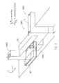
- Figure 3 shows the substrate table WT, and the intermediate structure IS.
- the reference structure has not been drawn for clarity reasons, however the skilled person will understand that the reference structure may be located over a top surface of the intermediate structure, a surface of the reference structure facing the intermediate structure being substantially parallel to a plane defined by the axis X and Y as defined in fig. 3.
- Figure 3 further shows an X-beam which may be comprised in a drive mechanism to move the substrate table along first axis indicated here as the Y-axis.
- the X-beam may therefor interface with a structure which extends along the Y-axis (not shown), the X-beam being movable with respect to such structure by any type of actuator, such as a linear motor.
- the actuator and the X-beam XB may form a first drive mechanism to move the substrate table along the first axis (i.e. the Y axis).
- the intermediate structure is connected or connectable to the X-beam, thus in general wording to the first drive mechanism, the intermediate structure thus following a movement of the substrate table along the first axis.
- the intermediate structure will follow this movement, as the intermediate structure is connected or connectable to the first drive mechanism, in this example e.g. connected to the X-beam XB.
- An advantage is that a distance between the substrate table and the intermediate structure does not or not significantly change when moving the substrate table along the first axis.
- the substrate table may be connectable to the drive mechanism by a clamping or other releasable mechanism, allowing the substrate table to be separated from the drive mechanism by releasing the clamping mechanism or other releasable mechanism, thus enabling the substrate table to be handled independently of the drive mechanism e.g. by another drive mechanism, such as may be the case in a so called dual stage lithographic apparatus.
- the lithographic apparatus may further comprise a second drive mechanism to move the substrate table along the X-axis, also indicated here as second axis.
- the second drive mechanism moves the substrate table WT with respect to in this embodiment the X-beam XB.
- a distance between the substrate table WT and the intermediate structure IS remains substantially constant, as a surface of the intermediate structure facing the substrate table WT extends substantially parallel to the X-axis.
- a movement of the substrate table along the Y-axis will be followed by the intermediate structure IS, thus not or only insignificantly affecting a distance between the substrate table and the intermediate structure as well as a distance between the intermediate structure and the reference structure, while a displacement of the substrate table WT along the X-axis leads to a displacement of the substrate table WT with respect to the intermediate structure IS along the X-axis, as the intermediate structure does not or substantially not follow such movement in this embodiment, thus not affecting a distance between the substrate table WT and the intermediate structure.
- the embodiment as shown in fig. 3 makes it possible to move the substrate table WT in both X and Y directions, while substantially maintaining a same distance between the substrate table WT and the intermediate structure as well as between the intermediate structure and the reference structure.
- the first measurement system FMS generates a plurality of first (optical) measurement beams between the intermediate structure and the substrate table, these measurement beams being in a direction substantially parallel to the first axis, thus the Y-axis.
- the second measurement system SMS may generate a plurality of second (optical) measurement beams between the intermediate structure and the reference structure, the second measurement beams being in a direction perpendicular to the Y-axis such as in this embodiment substantially perpendicular to the plane defined by the X and Y axes.
- a length of the measurement beams of the first and second measurement systems does not or not substantially change, thus the beam lengths of the measurement beams of the first and second measurement systems staying at there short length, substantially independently of a position or position movement of the substrate table WT. Therefore, any effect which would deteriorate an accuracy of the position measurements by the first a second measurement systems, is hardly present, as the measurement beams keep their relatively short lengths over a wide range of movement of the substrate table. With the current state of the art, it may be impossible to keep these short lengths with large movements of the substrate table.
- the present invention therefore reduces cost of- and gives design freedom of the substrate table.
- the second drive mechanism is arranged to move the substrate table with respect the first drive mechanism, however also other embodiments are possible, the second drive mechanism may e.g. move the substrate table with respect to a same reference as the first drive mechanism.
- the second drive mechanism may also comprise any type of suitable actuator, such as a linear motor, etc.
- the second measurement system SMS may also comprise second measurement beams which are substantially parallel to the second axis; providing same or similar advantages as the embodiments as described here.
- the arrows as depicted in the symbols representing sensors of the first and second measurement systems FMS, SMS do not indicate a direction of the measurement beam. In stead these sensors indicate a direction along which the respective sensor provides position information, thus a direction along which position information is provided by the respective position sensing device.
- the first and second measurement systems will now be described in more detail with reference to figure 4.
- the first measurement system comprises a plurality of interferometers and a plurality of encoders.
- the interferometers as well as the encoders comprise a measurement beam which extends substantially parallel to the first axis, thus the Y-axis.
- the first measurement system comprises a first interferometer IF 1, second interferometers IF2A, IF2B, and a third interferometer IF3, further, the first measurement system comprises a first encoder Enc1, a second encoder Enc2, and a third encoder Enc3.
- arrows originating at the respective interferometers and encoders in figure 4 indicate a direction of sensitivity of the respective interferometer or encoder.
- a physical appearance of the respective interferometer and encoder may differ from the highly schematic representation as depicted in figure 4.
- measurement beams for the interferometers resp. encoders are delivered by fibre delivery, thus optical fibres being e.g. comprised in the intermediate structure to guide the respective measurement beams to the appropriate locations of the respective interferometers and encoders.
- the first interferometer IF1 and the second interferometers IF2A, IF2B are separated from each other in a direction parallel to the X-axis, the third interferometer IF3 being separated from the first and second interferometers in a direction perpendicular to the X- and Y-axis.
- the first interferometer IF 1 in combination with second interferometer IF2A may be applied, or a combination of the first interferometer IF 1 and the second interferometer IF2B may be applied for position measurement.
- a large range of movement along the X-axis may be coped with by the second interferometers as an appropriate one of the second interferometers is selected for measurement.
- it is desired to obtain a position of a center of the substrate table in this example a middle point of a top surface of the substrate table.
- any tolerance on a measurement by the first measurement system in particular a tolerance in a measurement of a rotation of the substrate table around the X-axis, leads to relatively strong errors in a positions of the middle point of the substrate table.
- a distance between the interferometer IF 1 and IF3 has been chosen to be large, as the rotation around the X-axis is derived from an output value of the first and third interferometers.
- a distance between the first and second interferometers is comparably large, as from a read out of these interferometers, a rotation of the substrate table around the Z-axis is derived. Due to the long arm of the middle point of the substrate table towards the first measurement system, a high accuracy of these rotations is required, which is provided by the relatively large distances between the interferometers as mentioned.
- the first and second encoder Enc1, Enc2, may comprise a scale to measure a position in a direction substantially perpendicular to the X- and Y-axis.
- the scale may e.g. be connected to the substrate table WT, or may e.g. be comprised in a surface at a side of the substrate table which faces the intermediate structure.
- the third encoder Enc3 may comprise a scale to measure a position in a direction substantially parallel to the second axis, i.e. the X-axis. It is advantageous to connect the scales to the substrate table, or to integrated the scales into the substrate table WT, by using an e.g.
- first and second encoders are separated from each other in a direction parallel to the Y-axis while the third encoder is separated from the first and second encoders in a direction parallel to the Z-axis.
- the Ry is determined from measurements by the first and second encoder.
- a distance between the encoders may be smaller than a distance between the interferometers, because most of the measurements are close to the Y-axis of the projection system. Therefore, a rotation around the Y-axis (Ry) with such a short arm will have less influence. Thus, a required Ry accuracy for compensation of the arm is relatively small.
- the encoders or the interferometers are separated may be understood as referring to a physical distance between the measurement beams thereof, while this wording does not say anything about a physical positioning of a remainder of the interferometer or encoder in question.
- the wording 'are separated in a direction ....' Does not exclude a separation in any other direction, thus e.g. the wording 'interferometers IF1 and IF3 are separated in a direction along the Z-axis' does not exclude any separation along any other axis, thus the beams of these interferometers are in this example not necessarily located purely vertical with respect to each other.
- Figure 4 further shows the second measurement system SMS which comprises a fourth interferometer IF4, a fifth interferometer IF5, and a sixth interferometer IF6.
- the second measurement systems SMS comprises a fourth encoder Enc4, a fifth encoder Enc5, and a sixth encoder Enc6.
- the fourth and fifth interferometers IF4, IF5 are separated from each other in a direction parallel to the second axis.
- the sixth interferometer may be separated from the fourth and fifth interferometers in a direction parallel to the first axis.
- the fifth and sixth encoders Enc5, Enc6, may comprise a scale to measure a position in a direction substantially parallel to the Y-axis, while the fourth encoder Enc4 may comprise a scale to measure a position in a direction substantially to the second axis.
- the fifth and sixth encoders Enc5, Enc6, may be separated from each other in a direction parallel to the second axis.
- the intermediate structure may be connected e.g. at an extreme thereof to the first drive mechanism (or to any other suitable part) by a leaf spring or any other resilient or flexible member.
- the intermediate structure may comprise a material having a high thermal stability such as an invar material, and it preferably comprises a high stiffness.
- the intermediate structure preferably comprises a rectangular hollow or massive bar.
- FIG. 5 depicts the substrate table WT, intermediate structure IS, first measurement system FMS and second measurement system SMS, similar or identical to the ones described with reference to the previous figures. Further, figure 5 depicts the X-beam XB as described above. Further, the projection system PS is highly schematically indicated. Between the projection system PS (or more precisely between a down stream lens of the projection system PS) and the substrate held by the substrate table WT, a fluid supply system LS may be positioned to provide an immersion fluid (a liquid or a gas) to fill a space between the down stream projection element or projection lens and the substrate.
- an immersion fluid a liquid or a gas
- the intermediate structure IS may by applied to close the fluid supply system, thus preventing fluid from flowing out when e.g. replacing or moving away the substrate held by the substrate table WT. Therefore, the lithographic apparatus may be arranged to move to the substrate table WT plus the intermediate structure along the Y-axis in a direction to the left in the plane of drawing of figure 5, thus causing the projection system and fluid supply system to face the intermediate structure, in particular an area A thereof.
- the surface of the area A of the intermediate structure is now able to close the fluid supply system thus preventing immersion liquid from flowing away.
- it is possible to perform a pressure measurement relating to the pressure of the immersion fluid (immersion liquid or immersion gas) in the fluid supply system as the pressure may be derived from a displacement of the intermediate structure in this position, thus when the area A is applied as a closure plate for closing the fluid supply system.
- the higher a pressure of the immersion liquid the more a displacement of the intermediate structure may be observed, which may e.g. be detected by the second measurement system SMS.
- a sample pressure measurement device may be implemented to measure a pressure and/or a pressure profile of the immersion fluid in the liquid supply system, also indicated as immersion hood.
- the pressure measurement device may comprise, in addition or instead of the pressure measurement as described above, a plurality of sensors, such as pressure sensors, arranged in or on the intermediate structure, in particular in or on the surface A thereof.
- a pressure of the immersion fluid may be easily derived from a reading of these sensors.
- the sensors may comprise sensors to provide a pressure profile.
- the area A may of coarse form an integral part of the surface of the intermediate structure or may have any other suitable shape (such as rectangular, ellipse shaped, etc.).
- the area A may have a size which is substantially equal to a size of the liquid supply system or to a size of substrate, however the area A may also have a larger size which provides the advantage that it allows movement of the substrate table and thus possibly also of the intermediate structure connected to it, as the area A may is such case be large enough so that only a part of it provides the function of closing the liquid supply system and/or performing the measurements as described below.
- flexibility may be offered thereby, as some movements of the substrate table, e.g.
- the substrate table when performing activities in parallel by the lithographic apparatus, e.g. exchanging the substrate, swapping substrate tables in a dual stage lithographic apparatus etc., while at a same time offering immersion fluid supply closing functions and/or measuring functions by the intermediate structure as described here.
- the intermediate structure may comprise an immersion fluid filtration device to filter the immersion fluid.
- the filtration device may comprise an inlet, a filter and an outlet, the inlet leading from the surface of the area A and the outlet leading towards the surface of the are A.
- the filter may e.g. be located in the intermediate structure below the area A, the inlet and outlet leading from the filter to the area A. Further, it is possible that the surface of the intermediate structure to close the fluid supply system, e.g.
- the area A comprises a surface roughness which is substantially equal to a surface roughness of the substrate, thus providing substantially a same circulation resistance for a circulation of the immersion fluid, thus providing for a circulation of the immersion fluid which substantially equals a circulation of the fluid when the fluid supply system is closed by the substrate instead of by the area A, which therefore enables a highly accurate pressure measurement by the pressure measurement device described above, as a circulation of the fluid when closed by the area A substantially equals a circulation of the fluid when closed by the substrate.
- the measurement system and intermediate structure may not only be applied for a lithographic apparatus, but may be applied for any position apparatus in general, the positioning apparatus comprising a substrate table constructed to hold a substrate, a reference structure and a measurement system to measure a position of the substrate table with respect to the reference structure, wherein the measurement system comprises a first measurement system to measure a position of the substrate table with respect to an intermediate structure, and a second measurement system to measure a position of the intermediate structure with respect to the reference structure.
- Preferred embodiments of the lithographic apparatus as described above may also be implemented with the positioning apparatus as described here, providing same of similar advantages and effects.
- the intermediate structure may, in addition to or in stead of the features described above, further comprise one or more optical sensors O, such as a dose sensor to measure a dose as projected by the projection system, an image sensor such as a TIS (Transmission Image Sensor) sensor to measure an image plane flatness or an aerial image as projected by the projection system, and/or an aberration sensor to measure an aberration of the projection system. Measurements may be performed with these sensors when the intermediate structure has been positioned to e.g. hold the immersion fluid, thus the intermediate structure ( and in particular the area A thereof ) being positioned at or near a plane of focus of the projection system.
- optical sensors O such as a dose sensor to measure a dose as projected by the projection system
- an image sensor such as a TIS (Transmission Image Sensor) sensor to measure an image plane flatness or an aerial image as projected by the projection system
- an aberration sensor to measure an aberration of the projection system. Measurements may be performed with these sensors when the intermediate structure has been positioned to e.g. hold the immersion fluid, thus
- optical sensors as described above may have been comprised in the substrate table thus requiring an accurate positioning of the substrate table when performing measurements making use of these optical sensors.
- such measurements may be performed while only the intermediate structure is positioned to perform the measurements with the sensors, the substrate table may be used for other tasks at that moment in time (e.g. exchanging a wafer), thus allowing these tasks to be performed in parallel.
- the substrate table may be used for other tasks at that moment in time (e.g. exchanging a wafer), thus allowing these tasks to be performed in parallel.
- the intermediate structure may comprise positioning sensors (e.g. interferometers, pi ⁇ zo etc) to identify (a position of) the movable sensor(s) comprised in the intermediate structure.
- Figure 6 shows a schematic side view of an embodiment of the substrate table WT, the intermediate structure IS, the fluid supply system LS to hold the immersion fluid IFL and a lens at the downstream end of the projection system PS.
- the intermediate structure comprises an immersion fluid leakage drain IFLD to drain any immersion fluid which may leak between the substrate table WT and the intermediate structure IS when applying the intermediate structure as described with reference to figure 5.
- the drained immersion liquid may be reused, e.g. after filtering it by a suitable filtration device.
- a leakage stopper LST may be provided at an edge of a surface of the intermediate structure which surface may face the projection system, thus preventing a drain of immersion fluid at the edge.
- the first and second measurement systems may also comprise (but not limited to) capacitive sensors, photonic sensors, eddy current sensors, magnetic encoders or any other sensor that can preferably achieve (sub-) nm accuracy.
- the measurement system of the lithographic apparatus and positioning apparatus as described here may not only be applied for measuring a position of the substrate table, but may also be applied for measuring a position of any movable part (e.g. a stage comprising the substrate table, a mirror block carrying the substrate table) with respect to the reference structure, the first measurement system thus measuring a position of the movable part with respect to the intermediate structure.
- any movable part e.g. a stage comprising the substrate table, a mirror block carrying the substrate table
- the first measurement system thus measuring a position of the movable part with respect to the intermediate structure.
- the wording 'substrate table' may also be understood as to comprise any movable part of the lithographic apparatus and/or the positioning apparatus, such as the stage comprising the substrate table, the mirror block carrying the substrate table, etc.
- the invention may thus in alternative wording also be formulated as a lithographic apparatus comprising a stage comprising a substrate table constructed to hold a substrate, a reference structure and a measurement system to measure a position of the stage with respect to the reference structure, wherein the measurement system comprises a first measurement system to measure a position of a part of the stage with respect to an intermediate structure, and a second measurement system to measure a position of the intermediate structure with respect to the reference structure or as a lithographic apparatus comprising a stage comprising a mirror block carrying a substrate table constructed to hold a substrate, a reference structure, and a measurement system to measure a position of the mirror block with respect to the reference structure, wherein the measurement system comprises a first measurement system to measure a position of the mirror block with respect to an intermediate structure, and a second measurement system to measure a position of the intermediate structure with respect to the reference structure or as a positioning apparatus comprising a stage comprising a substrate table constructed to hold a substrate, a reference structure, and a measurement system to measure
- this invention is not limited to sensor heads on the intermediate structure and targets (e.g. mirrors and scales) on the substrate table and the reference structure respectively.
- targets e.g. mirrors and scales
- One or more of the sensor heads may also be mounted on the substrate table (or reference frame) with the targets on the intermediate structure.
- a redundant interferometer (e.g. indicated as IF7) can be added having a same X and Z position as interferometer IF 4 but having with regard to interferometer IF4 a same Y displacement as a distance between IF5 and IF6.
- This additional interferometer makes a metrology modeling easier and may improve accuracy of the position measurements even further.
- lithographic apparatus in the manufacture of ICs
- the lithographic apparatus described herein may have other applications, such as the manufacture of integrated optical systems, guidance and detection patterns for magnetic domain memories, flat-panel displays, liquid-crystal displays (LCDs), thin-film magnetic heads, etc.
- LCDs liquid-crystal displays
- any use of the terms “wafer” or “die” herein may be considered as synonymous with the more general terms “substrate” or "target portion”, respectively.
- imprint lithography a topography in a patterning device defines the pattern created on a substrate.
- the topography of the patterning device may be pressed into a layer of resist supplied to the substrate whereupon the resist is cured by applying electromagnetic radiation, heat, pressure or a combination thereof.
- the patterning device is moved out of the resist leaving a pattern in it after the resist is cured.
- lens may refer to any one or combination of various types of optical components, including refractive, reflective, magnetic, electromagnetic and electrostatic optical components.
- the invention may take the form of a computer program containing one or more sequences of machine-readable instructions describing a method as disclosed above, or a data storage medium (e.g. semiconductor memory, magnetic or optical disk) having such a computer program stored therein.
- a data storage medium e.g. semiconductor memory, magnetic or optical disk
Landscapes
- Physics & Mathematics (AREA)
- General Physics & Mathematics (AREA)
- Health & Medical Sciences (AREA)
- Engineering & Computer Science (AREA)
- Environmental & Geological Engineering (AREA)
- Epidemiology (AREA)
- Public Health (AREA)
- Exposure And Positioning Against Photoresist Photosensitive Materials (AREA)
- Exposure Of Semiconductors, Excluding Electron Or Ion Beam Exposure (AREA)
- Length Measuring Devices By Optical Means (AREA)
- Container, Conveyance, Adherence, Positioning, Of Wafer (AREA)
Applications Claiming Priority (2)
| Application Number | Priority Date | Filing Date | Title |
|---|---|---|---|
| US11/109,860 US7349069B2 (en) | 2005-04-20 | 2005-04-20 | Lithographic apparatus and positioning apparatus |
| US11/135,637 US7405811B2 (en) | 2005-04-20 | 2005-05-24 | Lithographic apparatus and positioning apparatus |
Publications (3)
| Publication Number | Publication Date |
|---|---|
| EP1715384A2 true EP1715384A2 (de) | 2006-10-25 |
| EP1715384A3 EP1715384A3 (de) | 2007-01-24 |
| EP1715384B1 EP1715384B1 (de) | 2010-01-13 |
Family
ID=36659800
Family Applications (1)
| Application Number | Title | Priority Date | Filing Date |
|---|---|---|---|
| EP06075927A Not-in-force EP1715384B1 (de) | 2005-04-20 | 2006-04-20 | Lithografische Vorrichtung und Positionierungsvorrichtung |
Country Status (7)
| Country | Link |
|---|---|
| US (1) | US7405811B2 (de) |
| EP (1) | EP1715384B1 (de) |
| JP (1) | JP4425876B2 (de) |
| KR (1) | KR100857258B1 (de) |
| DE (1) | DE602006011667D1 (de) |
| SG (1) | SG126883A1 (de) |
| TW (1) | TWI323392B (de) |
Cited By (5)
| Publication number | Priority date | Publication date | Assignee | Title |
|---|---|---|---|---|
| WO2009028696A1 (en) * | 2007-08-24 | 2009-03-05 | Nikon Corporation | Movable body drive method and movable body drive system |
| EP2095065A2 (de) * | 2006-11-15 | 2009-09-02 | Zygo Corporation | Messsysteme für distanzmessungsinterferometer und kodierer für lithografiewerkzeug |
| EP2128703A1 (de) * | 2008-05-28 | 2009-12-02 | ASML Netherlands BV | Lithographische Vorrichtung und Betriebsverfahren für die Vorrichtung |
| WO2010032884A1 (en) * | 2008-09-22 | 2010-03-25 | Nikon Corporation | Movable body apparatus and movable body drive method |
| US7894075B2 (en) | 2006-12-11 | 2011-02-22 | Zygo Corporation | Multiple-degree of freedom interferometer with compensation for gas effects |
Families Citing this family (46)
| Publication number | Priority date | Publication date | Assignee | Title |
|---|---|---|---|---|
| USRE43576E1 (en) | 2005-04-08 | 2012-08-14 | Asml Netherlands B.V. | Dual stage lithographic apparatus and device manufacturing method |
| EP3171220A1 (de) * | 2006-01-19 | 2017-05-24 | Nikon Corporation | Belichtungsvorrichtung, belichtungsverfahren und verfahren zur herstellung einer vorrichtung |
| JP5195417B2 (ja) | 2006-02-21 | 2013-05-08 | 株式会社ニコン | パターン形成装置、露光装置、露光方法及びデバイス製造方法 |
| WO2007097380A1 (ja) | 2006-02-21 | 2007-08-30 | Nikon Corporation | パターン形成装置及びパターン形成方法、移動体駆動システム及び移動体駆動方法、露光装置及び露光方法、並びにデバイス製造方法 |
| US8027021B2 (en) | 2006-02-21 | 2011-09-27 | Nikon Corporation | Measuring apparatus and method, processing apparatus and method, pattern forming apparatus and method, exposure apparatus and method, and device manufacturing method |
| TWI653511B (zh) | 2006-08-31 | 2019-03-11 | 日商尼康股份有限公司 | Exposure apparatus, exposure method, and component manufacturing method |
| CN103645608B (zh) | 2006-08-31 | 2016-04-20 | 株式会社尼康 | 曝光装置及方法、组件制造方法以及决定方法 |
| TWI572995B (zh) | 2006-08-31 | 2017-03-01 | 尼康股份有限公司 | Exposure method and exposure apparatus, and component manufacturing method |
| KR101660668B1 (ko) | 2006-09-01 | 2016-09-27 | 가부시키가이샤 니콘 | 이동체 구동 방법 및 이동체 구동 시스템, 패턴 형성 방법 및 장치, 노광 방법 및 장치, 그리고 디바이스 제조 방법 |
| TWI652720B (zh) | 2006-09-01 | 2019-03-01 | 日商尼康股份有限公司 | Exposure method and device and component manufacturing method |
| KR101360507B1 (ko) * | 2006-09-29 | 2014-02-07 | 가부시키가이샤 니콘 | 이동체 시스템, 패턴 형성 장치, 노광 장치 및 노광 방법, 그리고 디바이스 제조 방법 |
| US7903866B2 (en) | 2007-03-29 | 2011-03-08 | Asml Netherlands B.V. | Measurement system, lithographic apparatus and method for measuring a position dependent signal of a movable object |
| US8760615B2 (en) | 2007-05-24 | 2014-06-24 | Asml Netherlands B.V. | Lithographic apparatus having encoder type position sensor system |
| US8687166B2 (en) * | 2007-05-24 | 2014-04-01 | Asml Netherlands B.V. | Lithographic apparatus having an encoder position sensor system |
| US8237919B2 (en) * | 2007-08-24 | 2012-08-07 | Nikon Corporation | Movable body drive method and movable body drive system, pattern formation method and apparatus, exposure method and apparatus, and device manufacturing method for continuous position measurement of movable body before and after switching between sensor heads |
| US9013681B2 (en) * | 2007-11-06 | 2015-04-21 | Nikon Corporation | Movable body apparatus, pattern formation apparatus and exposure apparatus, and device manufacturing method |
| US9256140B2 (en) * | 2007-11-07 | 2016-02-09 | Nikon Corporation | Movable body apparatus, pattern formation apparatus and exposure apparatus, and device manufacturing method with measurement device to measure movable body in Z direction |
| US8665455B2 (en) | 2007-11-08 | 2014-03-04 | Nikon Corporation | Movable body apparatus, pattern formation apparatus and exposure apparatus, and device manufacturing method |
| US8422015B2 (en) * | 2007-11-09 | 2013-04-16 | Nikon Corporation | Movable body apparatus, pattern formation apparatus and exposure apparatus, and device manufacturing method |
| US8711327B2 (en) * | 2007-12-14 | 2014-04-29 | Nikon Corporation | Exposure apparatus, exposure method, and device manufacturing method |
| US8817236B2 (en) | 2008-05-13 | 2014-08-26 | Nikon Corporation | Movable body system, movable body drive method, pattern formation apparatus, pattern formation method, exposure apparatus, exposure method, and device manufacturing method |
| US8786829B2 (en) * | 2008-05-13 | 2014-07-22 | Nikon Corporation | Exposure apparatus, exposure method, and device manufacturing method |
| US8228482B2 (en) * | 2008-05-13 | 2012-07-24 | Nikon Corporation | Exposure apparatus, exposure method, and device manufacturing method |
| US8599359B2 (en) | 2008-12-19 | 2013-12-03 | Nikon Corporation | Exposure apparatus, exposure method, device manufacturing method, and carrier method |
| US8902402B2 (en) | 2008-12-19 | 2014-12-02 | Nikon Corporation | Movable body apparatus, exposure apparatus, exposure method, and device manufacturing method |
| US8760629B2 (en) | 2008-12-19 | 2014-06-24 | Nikon Corporation | Exposure apparatus including positional measurement system of movable body, exposure method of exposing object including measuring positional information of movable body, and device manufacturing method that includes exposure method of exposing object, including measuring positional information of movable body |
| US8773635B2 (en) * | 2008-12-19 | 2014-07-08 | Nikon Corporation | Exposure apparatus, exposure method, and device manufacturing method |
| US8493547B2 (en) | 2009-08-25 | 2013-07-23 | Nikon Corporation | Exposure apparatus, exposure method, and device manufacturing method |
| US8514395B2 (en) | 2009-08-25 | 2013-08-20 | Nikon Corporation | Exposure method, exposure apparatus, and device manufacturing method |
| US8488109B2 (en) | 2009-08-25 | 2013-07-16 | Nikon Corporation | Exposure method, exposure apparatus, and device manufacturing method |
| US20110102761A1 (en) * | 2009-09-28 | 2011-05-05 | Nikon Corporation | Stage apparatus, exposure apparatus, and device fabricating method |
| US20110096306A1 (en) * | 2009-09-28 | 2011-04-28 | Nikon Corporation | Stage apparatus, exposure apparatus, driving method, exposing method, and device fabricating method |
| US20110096318A1 (en) * | 2009-09-28 | 2011-04-28 | Nikon Corporation | Exposure apparatus and device fabricating method |
| US20110096312A1 (en) * | 2009-09-28 | 2011-04-28 | Nikon Corporation | Exposure apparatus and device fabricating method |
| US20110123913A1 (en) * | 2009-11-19 | 2011-05-26 | Nikon Corporation | Exposure apparatus, exposing method, and device fabricating method |
| US20110128523A1 (en) * | 2009-11-19 | 2011-06-02 | Nikon Corporation | Stage apparatus, exposure apparatus, driving method, exposing method, and device fabricating method |
| US8488106B2 (en) * | 2009-12-28 | 2013-07-16 | Nikon Corporation | Movable body drive method, movable body apparatus, exposure method, exposure apparatus, and device manufacturing method |
| EP2423749B1 (de) * | 2010-08-24 | 2013-09-11 | ASML Netherlands BV | Lithografische Vorrichtung und Verfahren zur Herstellung einer Vorrichtung |
| US9207549B2 (en) | 2011-12-29 | 2015-12-08 | Nikon Corporation | Exposure apparatus and exposure method, and device manufacturing method with encoder of higher reliability for position measurement |
| US20130182235A1 (en) * | 2012-01-12 | 2013-07-18 | Nikon Corporation | Measurement system that includes an encoder and an interferometer |
| US9529280B2 (en) * | 2013-12-06 | 2016-12-27 | Kla-Tencor Corporation | Stage apparatus for semiconductor inspection and lithography systems |
| EP3742109A1 (de) | 2015-02-23 | 2020-11-25 | Nikon Corporation | Messvorrichtung, lithographiesystem und belichtungsvorrichtung sowie vorrichtungsherstellungsverfahren |
| KR20230130161A (ko) | 2015-02-23 | 2023-09-11 | 가부시키가이샤 니콘 | 계측 장치, 리소그래피 시스템 및 노광 장치, 그리고 관리 방법, 중첩 계측 방법 및 디바이스 제조 방법 |
| JP6719729B2 (ja) | 2015-02-23 | 2020-07-08 | 株式会社ニコン | 基板処理システム及び基板処理方法、並びにデバイス製造方法 |
| CN108139685B (zh) * | 2015-09-30 | 2020-12-04 | 株式会社尼康 | 曝光装置、平面显示器的制造方法、组件制造方法、及曝光方法 |
| DE102021106289A1 (de) * | 2020-05-07 | 2021-11-11 | Taiwan Semiconductor Manufacturing Co., Ltd. | System und verfahren zum ausführen von extrem-ultraviolett-photolithografieprozessen |
Citations (2)
| Publication number | Priority date | Publication date | Assignee | Title |
|---|---|---|---|---|
| US4676649A (en) | 1985-11-27 | 1987-06-30 | Compact Spindle Bearing Corp. | Multi-axis gas bearing stage assembly |
| US4891526A (en) | 1986-12-29 | 1990-01-02 | Hughes Aircraft Company | X-Y-θ-Z positioning stage |
Family Cites Families (10)
| Publication number | Priority date | Publication date | Assignee | Title |
|---|---|---|---|---|
| US3617126A (en) * | 1969-11-10 | 1971-11-02 | Jodon Engineering Associates | Repositioning apparatus for photographic plates |
| US6208407B1 (en) * | 1997-12-22 | 2001-03-27 | Asm Lithography B.V. | Method and apparatus for repetitively projecting a mask pattern on a substrate, using a time-saving height measurement |
| JPH11189332A (ja) * | 1997-12-26 | 1999-07-13 | Canon Inc | ステージ装置およびこれを用いた露光装置ならびにデバイス製造方法 |
| US7289212B2 (en) | 2000-08-24 | 2007-10-30 | Asml Netherlands B.V. | Lithographic apparatus, device manufacturing method and device manufacturing thereby |
| US6686991B1 (en) * | 2000-11-06 | 2004-02-03 | Nikon Corporation | Wafer stage assembly, servo control system, and method for operating the same |
| US6665054B2 (en) * | 2001-10-22 | 2003-12-16 | Nikon Corporation | Two stage method |
| WO2004031855A2 (en) * | 2002-10-02 | 2004-04-15 | Mykrolis Corporation | Membrane and reticle-pellicle apparatus with purged pellicle-to-reticle gap using same |
| EP1420299B1 (de) | 2002-11-12 | 2011-01-05 | ASML Netherlands B.V. | Lithographischer Apparat mit Immersion und Verfahren zur Herstellung einer Vorrichtung |
| SG147288A1 (en) * | 2003-04-29 | 2008-11-28 | Asml Netherlands Bv | Lithographic apparatus, device manufacturing method and angular encoder |
| JP2007522668A (ja) | 2004-02-11 | 2007-08-09 | コーニンクレッカ フィリップス エレクトロニクス エヌ ヴィ | 製造物の位置決めシステム |
-
2005
- 2005-05-24 US US11/135,637 patent/US7405811B2/en not_active Expired - Fee Related
-
2006
- 2006-04-07 TW TW095112560A patent/TWI323392B/zh not_active IP Right Cessation
- 2006-04-18 SG SG200602542A patent/SG126883A1/en unknown
- 2006-04-19 JP JP2006115230A patent/JP4425876B2/ja not_active Expired - Fee Related
- 2006-04-19 KR KR1020060035499A patent/KR100857258B1/ko not_active IP Right Cessation
- 2006-04-20 DE DE602006011667T patent/DE602006011667D1/de active Active
- 2006-04-20 EP EP06075927A patent/EP1715384B1/de not_active Not-in-force
Patent Citations (2)
| Publication number | Priority date | Publication date | Assignee | Title |
|---|---|---|---|---|
| US4676649A (en) | 1985-11-27 | 1987-06-30 | Compact Spindle Bearing Corp. | Multi-axis gas bearing stage assembly |
| US4891526A (en) | 1986-12-29 | 1990-01-02 | Hughes Aircraft Company | X-Y-θ-Z positioning stage |
Cited By (14)
| Publication number | Priority date | Publication date | Assignee | Title |
|---|---|---|---|---|
| EP2095065A4 (de) * | 2006-11-15 | 2010-11-24 | Zygo Corp | Messsysteme für distanzmessungsinterferometer und kodierer für lithografiewerkzeug |
| EP2095065A2 (de) * | 2006-11-15 | 2009-09-02 | Zygo Corporation | Messsysteme für distanzmessungsinterferometer und kodierer für lithografiewerkzeug |
| US7894075B2 (en) | 2006-12-11 | 2011-02-22 | Zygo Corporation | Multiple-degree of freedom interferometer with compensation for gas effects |
| US8767182B2 (en) | 2007-08-24 | 2014-07-01 | Nikon Corporation | Movable body drive method and movable body drive system, pattern formation method and apparatus, exposure method and apparatus, and device manufacturing method |
| US8023106B2 (en) | 2007-08-24 | 2011-09-20 | Nikon Corporation | Movable body drive method and movable body drive system, pattern formation method and apparatus, exposure method and apparatus, and device manufacturing method |
| WO2009028696A1 (en) * | 2007-08-24 | 2009-03-05 | Nikon Corporation | Movable body drive method and movable body drive system |
| EP2128703A1 (de) * | 2008-05-28 | 2009-12-02 | ASML Netherlands BV | Lithographische Vorrichtung und Betriebsverfahren für die Vorrichtung |
| US9176393B2 (en) | 2008-05-28 | 2015-11-03 | Asml Netherlands B.V. | Lithographic apparatus and a method of operating the apparatus |
| US11187991B2 (en) | 2008-05-28 | 2021-11-30 | Asml Netherlands B.V. | Lithographic apparatus and a method of operating the apparatus |
| WO2010032884A1 (en) * | 2008-09-22 | 2010-03-25 | Nikon Corporation | Movable body apparatus and movable body drive method |
| US8508735B2 (en) | 2008-09-22 | 2013-08-13 | Nikon Corporation | Movable body apparatus, movable body drive method, exposure apparatus, exposure method, and device manufacturing method |
| US8593632B1 (en) | 2008-09-22 | 2013-11-26 | Nikon Corporation | Movable body apparatus, movable body drive method, exposure apparatus, exposure method, and device manufacturing method |
| TWI485526B (zh) * | 2008-09-22 | 2015-05-21 | 尼康股份有限公司 | Mobile device and moving body driving method, exposure apparatus and exposure method, and component manufacturing method |
| TWI559098B (zh) * | 2008-09-22 | 2016-11-21 | 尼康股份有限公司 | Mobile device and moving body driving method, exposure apparatus and exposure method, and component manufacturing method |
Also Published As
| Publication number | Publication date |
|---|---|
| TWI323392B (en) | 2010-04-11 |
| KR100857258B1 (ko) | 2008-09-05 |
| EP1715384B1 (de) | 2010-01-13 |
| JP4425876B2 (ja) | 2010-03-03 |
| SG126883A1 (en) | 2006-11-29 |
| TW200707133A (en) | 2007-02-16 |
| KR20060110807A (ko) | 2006-10-25 |
| EP1715384A3 (de) | 2007-01-24 |
| JP2006303505A (ja) | 2006-11-02 |
| US7405811B2 (en) | 2008-07-29 |
| US20060238733A1 (en) | 2006-10-26 |
| DE602006011667D1 (de) | 2010-03-04 |
Similar Documents
| Publication | Publication Date | Title |
|---|---|---|
| EP1715384B1 (de) | Lithografische Vorrichtung und Positionierungsvorrichtung | |
| US7349069B2 (en) | Lithographic apparatus and positioning apparatus | |
| US7102729B2 (en) | Lithographic apparatus, measurement system, and device manufacturing method | |
| KR101549710B1 (ko) | 이동체 구동 시스템, 패턴 형성 장치, 노광 장치 및 노광 방법, 그리고 디바이스 제조 방법 | |
| EP3115844B1 (de) | Belichtungsapparat, belichtungsverfahren und verfahren zur herstellung einer vorrichtung | |
| US8319940B2 (en) | Position measurement system and lithographic apparatus | |
| US20060139595A1 (en) | Lithographic apparatus and method for determining Z position errors/variations and substrate table flatness | |
| JP5582165B2 (ja) | 測定装置、測定方法及びステージ装置 | |
| KR101651447B1 (ko) | 정량적 레티클 왜곡 측정 시스템 | |
| NL2005013A (en) | Positioning system, lithographic apparatus and method. | |
| US10976675B2 (en) | Lithographic apparatus | |
| US20150241795A1 (en) | Method for calibration of an encoder scale and a lithographic apparatus | |
| NL2010967A (en) | Positioning system, lithographic apparatus and device manufacturing method. | |
| US7426011B2 (en) | Method of calibrating a lithographic apparatus and device manufacturing method | |
| US7283249B2 (en) | Lithographic apparatus and a method of calibrating such an apparatus | |
| US8982359B2 (en) | System for detecting motion, lithographic apparatus and device manufacturing method | |
| US20060139590A1 (en) | Lithographic apparatus and device manufacturing method | |
| KR101671824B1 (ko) | 리소그래피 장치, 디바이스 제조 방법 및 이격 측정 시스템 |
Legal Events
| Date | Code | Title | Description |
|---|---|---|---|
| PUAI | Public reference made under article 153(3) epc to a published international application that has entered the european phase |
Free format text: ORIGINAL CODE: 0009012 |
|
| AK | Designated contracting states |
Kind code of ref document: A2 Designated state(s): AT BE BG CH CY CZ DE DK EE ES FI FR GB GR HU IE IS IT LI LT LU LV MC NL PL PT RO SE SI SK TR |
|
| AX | Request for extension of the european patent |
Extension state: AL BA HR MK YU |
|
| PUAL | Search report despatched |
Free format text: ORIGINAL CODE: 0009013 |
|
| AK | Designated contracting states |
Kind code of ref document: A3 Designated state(s): AT BE BG CH CY CZ DE DK EE ES FI FR GB GR HU IE IS IT LI LT LU LV MC NL PL PT RO SE SI SK TR |
|
| AX | Request for extension of the european patent |
Extension state: AL BA HR MK YU |
|
| 17P | Request for examination filed |
Effective date: 20070723 |
|
| 17Q | First examination report despatched |
Effective date: 20070823 |
|
| AKX | Designation fees paid |
Designated state(s): DE FR GB IT NL |
|
| GRAP | Despatch of communication of intention to grant a patent |
Free format text: ORIGINAL CODE: EPIDOSNIGR1 |
|
| GRAS | Grant fee paid |
Free format text: ORIGINAL CODE: EPIDOSNIGR3 |
|
| GRAA | (expected) grant |
Free format text: ORIGINAL CODE: 0009210 |
|
| AK | Designated contracting states |
Kind code of ref document: B1 Designated state(s): DE FR GB IT NL |
|
| REG | Reference to a national code |
Ref country code: GB Ref legal event code: FG4D |
|
| REF | Corresponds to: |
Ref document number: 602006011667 Country of ref document: DE Date of ref document: 20100304 Kind code of ref document: P |
|
| REG | Reference to a national code |
Ref country code: NL Ref legal event code: VDEP Effective date: 20100113 |
|
| PG25 | Lapsed in a contracting state [announced via postgrant information from national office to epo] |
Ref country code: NL Free format text: LAPSE BECAUSE OF FAILURE TO SUBMIT A TRANSLATION OF THE DESCRIPTION OR TO PAY THE FEE WITHIN THE PRESCRIBED TIME-LIMIT Effective date: 20100113 |
|
| PLBE | No opposition filed within time limit |
Free format text: ORIGINAL CODE: 0009261 |
|
| STAA | Information on the status of an ep patent application or granted ep patent |
Free format text: STATUS: NO OPPOSITION FILED WITHIN TIME LIMIT |
|
| 26N | No opposition filed |
Effective date: 20101014 |
|
| GBPC | Gb: european patent ceased through non-payment of renewal fee |
Effective date: 20100420 |
|
| PG25 | Lapsed in a contracting state [announced via postgrant information from national office to epo] |
Ref country code: IT Free format text: LAPSE BECAUSE OF FAILURE TO SUBMIT A TRANSLATION OF THE DESCRIPTION OR TO PAY THE FEE WITHIN THE PRESCRIBED TIME-LIMIT Effective date: 20100113 Ref country code: GB Free format text: LAPSE BECAUSE OF NON-PAYMENT OF DUE FEES Effective date: 20100420 |
|
| PGFP | Annual fee paid to national office [announced via postgrant information from national office to epo] |
Ref country code: FR Payment date: 20140422 Year of fee payment: 9 Ref country code: DE Payment date: 20140418 Year of fee payment: 9 |
|
| REG | Reference to a national code |
Ref country code: DE Ref legal event code: R119 Ref document number: 602006011667 Country of ref document: DE |
|
| PG25 | Lapsed in a contracting state [announced via postgrant information from national office to epo] |
Ref country code: DE Free format text: LAPSE BECAUSE OF NON-PAYMENT OF DUE FEES Effective date: 20151103 |
|
| REG | Reference to a national code |
Ref country code: FR Ref legal event code: ST Effective date: 20151231 |
|
| PG25 | Lapsed in a contracting state [announced via postgrant information from national office to epo] |
Ref country code: FR Free format text: LAPSE BECAUSE OF NON-PAYMENT OF DUE FEES Effective date: 20150430 |