EP1715329A1 - Particle inspection apparatus and method, exposure apparatus, and device manufacturing method - Google Patents
Particle inspection apparatus and method, exposure apparatus, and device manufacturing method Download PDFInfo
- Publication number
- EP1715329A1 EP1715329A1 EP06003289A EP06003289A EP1715329A1 EP 1715329 A1 EP1715329 A1 EP 1715329A1 EP 06003289 A EP06003289 A EP 06003289A EP 06003289 A EP06003289 A EP 06003289A EP 1715329 A1 EP1715329 A1 EP 1715329A1
- Authority
- EP
- European Patent Office
- Prior art keywords
- light
- inspection
- shield
- reticle
- particle
- Prior art date
- Legal status (The legal status is an assumption and is not a legal conclusion. Google has not performed a legal analysis and makes no representation as to the accuracy of the status listed.)
- Withdrawn
Links
Images


Classifications
-
- G—PHYSICS
- G01—MEASURING; TESTING
- G01N—INVESTIGATING OR ANALYSING MATERIALS BY DETERMINING THEIR CHEMICAL OR PHYSICAL PROPERTIES
- G01N21/00—Investigating or analysing materials by the use of optical means, i.e. using sub-millimetre waves, infrared, visible or ultraviolet light
- G01N21/84—Systems specially adapted for particular applications
- G01N21/88—Investigating the presence of flaws or contamination
- G01N21/94—Investigating contamination, e.g. dust
-
- G—PHYSICS
- G02—OPTICS
- G02F—OPTICAL DEVICES OR ARRANGEMENTS FOR THE CONTROL OF LIGHT BY MODIFICATION OF THE OPTICAL PROPERTIES OF THE MEDIA OF THE ELEMENTS INVOLVED THEREIN; NON-LINEAR OPTICS; FREQUENCY-CHANGING OF LIGHT; OPTICAL LOGIC ELEMENTS; OPTICAL ANALOGUE/DIGITAL CONVERTERS
- G02F1/00—Devices or arrangements for the control of the intensity, colour, phase, polarisation or direction of light arriving from an independent light source, e.g. switching, gating or modulating; Non-linear optics
- G02F1/01—Devices or arrangements for the control of the intensity, colour, phase, polarisation or direction of light arriving from an independent light source, e.g. switching, gating or modulating; Non-linear optics for the control of the intensity, phase, polarisation or colour
- G02F1/13—Devices or arrangements for the control of the intensity, colour, phase, polarisation or direction of light arriving from an independent light source, e.g. switching, gating or modulating; Non-linear optics for the control of the intensity, phase, polarisation or colour based on liquid crystals, e.g. single liquid crystal display cells
- G02F1/133—Constructional arrangements; Operation of liquid crystal cells; Circuit arrangements
- G02F1/1333—Constructional arrangements; Manufacturing methods
- G02F1/1335—Structural association of cells with optical devices, e.g. polarisers or reflectors
- G02F1/1336—Illuminating devices
- G02F1/133602—Direct backlight
- G02F1/133611—Direct backlight including means for improving the brightness uniformity
-
- G—PHYSICS
- G02—OPTICS
- G02F—OPTICAL DEVICES OR ARRANGEMENTS FOR THE CONTROL OF LIGHT BY MODIFICATION OF THE OPTICAL PROPERTIES OF THE MEDIA OF THE ELEMENTS INVOLVED THEREIN; NON-LINEAR OPTICS; FREQUENCY-CHANGING OF LIGHT; OPTICAL LOGIC ELEMENTS; OPTICAL ANALOGUE/DIGITAL CONVERTERS
- G02F1/00—Devices or arrangements for the control of the intensity, colour, phase, polarisation or direction of light arriving from an independent light source, e.g. switching, gating or modulating; Non-linear optics
- G02F1/01—Devices or arrangements for the control of the intensity, colour, phase, polarisation or direction of light arriving from an independent light source, e.g. switching, gating or modulating; Non-linear optics for the control of the intensity, phase, polarisation or colour
- G02F1/13—Devices or arrangements for the control of the intensity, colour, phase, polarisation or direction of light arriving from an independent light source, e.g. switching, gating or modulating; Non-linear optics for the control of the intensity, phase, polarisation or colour based on liquid crystals, e.g. single liquid crystal display cells
- G02F1/133—Constructional arrangements; Operation of liquid crystal cells; Circuit arrangements
- G02F1/1333—Constructional arrangements; Manufacturing methods
- G02F1/1335—Structural association of cells with optical devices, e.g. polarisers or reflectors
- G02F1/1336—Illuminating devices
- G02F1/133602—Direct backlight
- G02F1/133603—Direct backlight with LEDs
-
- G—PHYSICS
- G02—OPTICS
- G02F—OPTICAL DEVICES OR ARRANGEMENTS FOR THE CONTROL OF LIGHT BY MODIFICATION OF THE OPTICAL PROPERTIES OF THE MEDIA OF THE ELEMENTS INVOLVED THEREIN; NON-LINEAR OPTICS; FREQUENCY-CHANGING OF LIGHT; OPTICAL LOGIC ELEMENTS; OPTICAL ANALOGUE/DIGITAL CONVERTERS
- G02F1/00—Devices or arrangements for the control of the intensity, colour, phase, polarisation or direction of light arriving from an independent light source, e.g. switching, gating or modulating; Non-linear optics
- G02F1/01—Devices or arrangements for the control of the intensity, colour, phase, polarisation or direction of light arriving from an independent light source, e.g. switching, gating or modulating; Non-linear optics for the control of the intensity, phase, polarisation or colour
- G02F1/13—Devices or arrangements for the control of the intensity, colour, phase, polarisation or direction of light arriving from an independent light source, e.g. switching, gating or modulating; Non-linear optics for the control of the intensity, phase, polarisation or colour based on liquid crystals, e.g. single liquid crystal display cells
- G02F1/133—Constructional arrangements; Operation of liquid crystal cells; Circuit arrangements
- G02F1/1333—Constructional arrangements; Manufacturing methods
- G02F1/1335—Structural association of cells with optical devices, e.g. polarisers or reflectors
- G02F1/1336—Illuminating devices
- G02F1/133602—Direct backlight
- G02F1/133605—Direct backlight including specially adapted reflectors
-
- G—PHYSICS
- G02—OPTICS
- G02F—OPTICAL DEVICES OR ARRANGEMENTS FOR THE CONTROL OF LIGHT BY MODIFICATION OF THE OPTICAL PROPERTIES OF THE MEDIA OF THE ELEMENTS INVOLVED THEREIN; NON-LINEAR OPTICS; FREQUENCY-CHANGING OF LIGHT; OPTICAL LOGIC ELEMENTS; OPTICAL ANALOGUE/DIGITAL CONVERTERS
- G02F1/00—Devices or arrangements for the control of the intensity, colour, phase, polarisation or direction of light arriving from an independent light source, e.g. switching, gating or modulating; Non-linear optics
- G02F1/01—Devices or arrangements for the control of the intensity, colour, phase, polarisation or direction of light arriving from an independent light source, e.g. switching, gating or modulating; Non-linear optics for the control of the intensity, phase, polarisation or colour
- G02F1/13—Devices or arrangements for the control of the intensity, colour, phase, polarisation or direction of light arriving from an independent light source, e.g. switching, gating or modulating; Non-linear optics for the control of the intensity, phase, polarisation or colour based on liquid crystals, e.g. single liquid crystal display cells
- G02F1/133—Constructional arrangements; Operation of liquid crystal cells; Circuit arrangements
- G02F1/1333—Constructional arrangements; Manufacturing methods
- G02F1/1335—Structural association of cells with optical devices, e.g. polarisers or reflectors
- G02F1/1336—Illuminating devices
- G02F1/133602—Direct backlight
- G02F1/133606—Direct backlight including a specially adapted diffusing, scattering or light controlling members
-
- G—PHYSICS
- G02—OPTICS
- G02F—OPTICAL DEVICES OR ARRANGEMENTS FOR THE CONTROL OF LIGHT BY MODIFICATION OF THE OPTICAL PROPERTIES OF THE MEDIA OF THE ELEMENTS INVOLVED THEREIN; NON-LINEAR OPTICS; FREQUENCY-CHANGING OF LIGHT; OPTICAL LOGIC ELEMENTS; OPTICAL ANALOGUE/DIGITAL CONVERTERS
- G02F1/00—Devices or arrangements for the control of the intensity, colour, phase, polarisation or direction of light arriving from an independent light source, e.g. switching, gating or modulating; Non-linear optics
- G02F1/01—Devices or arrangements for the control of the intensity, colour, phase, polarisation or direction of light arriving from an independent light source, e.g. switching, gating or modulating; Non-linear optics for the control of the intensity, phase, polarisation or colour
- G02F1/13—Devices or arrangements for the control of the intensity, colour, phase, polarisation or direction of light arriving from an independent light source, e.g. switching, gating or modulating; Non-linear optics for the control of the intensity, phase, polarisation or colour based on liquid crystals, e.g. single liquid crystal display cells
- G02F1/133—Constructional arrangements; Operation of liquid crystal cells; Circuit arrangements
- G02F1/1333—Constructional arrangements; Manufacturing methods
- G02F1/1335—Structural association of cells with optical devices, e.g. polarisers or reflectors
- G02F1/1336—Illuminating devices
- G02F1/133602—Direct backlight
- G02F1/133608—Direct backlight including particular frames or supporting means
-
- G—PHYSICS
- G03—PHOTOGRAPHY; CINEMATOGRAPHY; ANALOGOUS TECHNIQUES USING WAVES OTHER THAN OPTICAL WAVES; ELECTROGRAPHY; HOLOGRAPHY
- G03F—PHOTOMECHANICAL PRODUCTION OF TEXTURED OR PATTERNED SURFACES, e.g. FOR PRINTING, FOR PROCESSING OF SEMICONDUCTOR DEVICES; MATERIALS THEREFOR; ORIGINALS THEREFOR; APPARATUS SPECIALLY ADAPTED THEREFOR
- G03F1/00—Originals for photomechanical production of textured or patterned surfaces, e.g., masks, photo-masks, reticles; Mask blanks or pellicles therefor; Containers specially adapted therefor; Preparation thereof
- G03F1/62—Pellicles, e.g. pellicle assemblies, e.g. having membrane on support frame; Preparation thereof
-
- G—PHYSICS
- G03—PHOTOGRAPHY; CINEMATOGRAPHY; ANALOGOUS TECHNIQUES USING WAVES OTHER THAN OPTICAL WAVES; ELECTROGRAPHY; HOLOGRAPHY
- G03F—PHOTOMECHANICAL PRODUCTION OF TEXTURED OR PATTERNED SURFACES, e.g. FOR PRINTING, FOR PROCESSING OF SEMICONDUCTOR DEVICES; MATERIALS THEREFOR; ORIGINALS THEREFOR; APPARATUS SPECIALLY ADAPTED THEREFOR
- G03F1/00—Originals for photomechanical production of textured or patterned surfaces, e.g., masks, photo-masks, reticles; Mask blanks or pellicles therefor; Containers specially adapted therefor; Preparation thereof
- G03F1/68—Preparation processes not covered by groups G03F1/20 - G03F1/50
- G03F1/82—Auxiliary processes, e.g. cleaning or inspecting
- G03F1/84—Inspecting
-
- G—PHYSICS
- G01—MEASURING; TESTING
- G01N—INVESTIGATING OR ANALYSING MATERIALS BY DETERMINING THEIR CHEMICAL OR PHYSICAL PROPERTIES
- G01N21/00—Investigating or analysing materials by the use of optical means, i.e. using sub-millimetre waves, infrared, visible or ultraviolet light
- G01N21/84—Systems specially adapted for particular applications
- G01N21/88—Investigating the presence of flaws or contamination
- G01N21/95—Investigating the presence of flaws or contamination characterised by the material or shape of the object to be examined
- G01N21/956—Inspecting patterns on the surface of objects
- G01N2021/95676—Masks, reticles, shadow masks
-
- G—PHYSICS
- G01—MEASURING; TESTING
- G01N—INVESTIGATING OR ANALYSING MATERIALS BY DETERMINING THEIR CHEMICAL OR PHYSICAL PROPERTIES
- G01N2201/00—Features of devices classified in G01N21/00
- G01N2201/06—Illumination; Optics
- G01N2201/064—Stray light conditioning
- G01N2201/0642—Light traps; baffles
-
- G—PHYSICS
- G03—PHOTOGRAPHY; CINEMATOGRAPHY; ANALOGOUS TECHNIQUES USING WAVES OTHER THAN OPTICAL WAVES; ELECTROGRAPHY; HOLOGRAPHY
- G03F—PHOTOMECHANICAL PRODUCTION OF TEXTURED OR PATTERNED SURFACES, e.g. FOR PRINTING, FOR PROCESSING OF SEMICONDUCTOR DEVICES; MATERIALS THEREFOR; ORIGINALS THEREFOR; APPARATUS SPECIALLY ADAPTED THEREFOR
- G03F1/00—Originals for photomechanical production of textured or patterned surfaces, e.g., masks, photo-masks, reticles; Mask blanks or pellicles therefor; Containers specially adapted therefor; Preparation thereof
- G03F1/68—Preparation processes not covered by groups G03F1/20 - G03F1/50
- G03F1/82—Auxiliary processes, e.g. cleaning or inspecting
Definitions
- the present invention relates to a particle inspection technique for inspecting the surface of an object for a particle, and an exposure technique using the particle inspection technique.
- a reduction projection exposure apparatus is used to form by exposure a circuit pattern drawn on a reticle or mask by reducing and projecting it onto a wafer coated with a photosensitive agent. Along with an increase in mounting density of a semiconductor element, further micropatterning is required.
- the exposure apparatus takes a measure to implement micropatterning at the same time as the development of a resist process.
- a mask or reticle generally has a pattern protective member called a pellicle consisting of transparent thin films which are made of cellulose nitrate and have a thickness of about 1 ⁇ m. This prevents a particle such as dust from adhering to the reticle pattern surface.
- a defocused image of the particle adhering to the above-mentioned surface may possibly be transferred, so the light amount varies on the wafer, resulting in unsatisfactory exposure.
- a general method takes advantage of a nature in which a particle diffuses light isotropically. For example, parallel light beams are collectively applied to the inspection surface region obliquely from above. Scattered light from a particle is applied onto a one-dimensional image sensor (sensor array) by a microlens array of refractive index distribution type to image the particle. Then, the inspection surface is inspected to detect the presence/absence of a particle (to be referred to as a foreign particle or contaminant hereinafter).
- Fig. 12 is a view showing an outline of the structure of a particle inspection apparatus.
- a reticle 1 and pellicle 2 (not shown) as inspection objects are held on an inspection table 6.
- An inspection light forming unit (to be also referred to as an irradiator) 7 forms inspection light and irradiates an inspection object with it.
- a reticle-side detector 3 faces the reticle 1 and detects inspection light applied to the reticle 1.
- a pellicle-side detector 4 faces the pellicle 2 and detects inspection light applied to the pellicle 2.
- the inspection light forming unit 7 scans the reticle-side detector 3 and pellicle-side detector 4 in the direction of an arrow (x direction) with respect to an inspection object to inspect the entire surface of the inspection object for a particle.
- Fig. 13 is a side view of Fig. 12 when viewed from the x direction, and a structure on the pellicle 2 side is omitted.
- the inspection light forming unit 7 collectively applies inspection light beams 14a as parallel light beams to the reticle 1.
- the applied inspection light beams are detected by the detector 3 to detect a particle.
- part of the inspection light beams 14a emitted from the inspection light forming unit 7 comes from an edge portion 1a (end face portion) of the reticle 1 and enters the reticle 1.
- the entered inspection light is sometimes diffracted by a pattern 20 drawn on the reticle 1 to generate a diffraction light beam 21.
- the diffraction light beam 21 strikes the detector 3, it is erroneously detected as scattered light from a particle. This disables accurate particle detection.
- a shield member is conventionally arranged in a direction in which scattered light from a particle is not shielded while shielding stray light such as diffraction light in a detector.
- stray light such as diffraction light in a detector.
- a direction in which diffraction light is generated depends on the pattern of a reticle, so it is difficult to shield diffraction light in every state.
- the present invention has been made in consideration of the above background, and has as its exemplary object to provide a novel technique for realizing particle inspection with high accuracy.
- an inspection apparatus for inspecting a surface of an object for a particle, comprising: an irradiator configured to irradiate the surface with inspection light; a first detector configured to detect light scattered at the surface; and a shield configured to limit an irradiation region of the inspection light emitted by the irradiator within a limited region of the surface.
- an inspection method of inspecting a surface of an object for a particle comprising: an emission step of emitting inspection light; a shield step of shielding the inspection light with a shield to limit an irradiation region of the emitted inspection light within a limited region of the surface; and a first detection step of detecting light scattered at the surface irradiated with the shielded inspection light.
- the present invention can also be applied to an exposure apparatus for exposing a substrate to light via a reticle having the above inspection apparatus, and a method of manufacturing a device, comprising steps of: exposing a substrate to light via a reticle using an exposure apparatus as defined above; developing the exposed substrate; and processing the developed substrate to manufacture the device.
- the present invention makes it possible to provide a novel technique for realizing particle inspection with high accuracy.
- Fig. 1 is a view showing an outline of the structure of a particle inspection apparatus according to the first embodiment of the present invention.
- a laser beam emitted from a laser diode 8 is converted into a parallel light beam by a collimator lens 9.
- the collimated laser beam is split by a beam splitter (half mirror) 10a into two light beams A and B having almost the same intensity with each other.
- a transmitted light beam B transmitted through the beam splitter 10a is applied to a beam splitter 10b.
- a reflected light beam A reflected by the beam splitter 10b is applied to a cube corner reflector 18.
- the cube corner reflector 18 is arranged to be shifted from the beam splitters 10a and 10b in the x direction by a predetermined amount L/2.
- the light beams A and B are combined in the beam splitter 10b. After that, light beams Aa and Ba emitted from the beam splitter 10b in the x direction become parallel with each other, and form a shape in which the centers of the two light beams are spaced by a distance L.
- the beam splitter 10b Since the beam splitter 10b is a half mirror, it emits light beams Ab and Bb in the z direction, the centers of which are spaced by the distance L.
- Combined light beams (Aa + Ba) and (Ab + Bb) are applied, as inspection light beams 14a and 14b in two directions, to the upper surface (inspection surface) of a reticle 1 and the lower surface (inspection surface) of a pellicle 2, respectively.
- the inspection light beams 14a and 14b formed into a vertically long shape by the beam splitters 10a and 10b are obliquely applied to the surfaces of the reticle 1 and pellicle 2 at a predetermined angle by reflectors (mirrors) 11, 12, and 13, thus forming almost uniform slit light on the inspection surfaces.
- detectors 3 and 4 and inspection light forming unit 7 are scanned in the x direction with respect to the reticle 1 and pellicle 2 to inspect the entire inspection surface of the inspection object for a particle. If a particle 17 is present in the irradiation region of inspection light, scattered light is generated from the particle. The scattered light is imaged on a line sensor 16 by lens array 15 arranged along the irradiation region of inspection light.
- a characteristic feature of this embodiment is that a shield (plate) 5 is so arranged as to limit the irradiation range of inspection light such that the inspection light 14a is prevented from striking the edge portion of the inspection object.
- Fig. 2 is a side view of Fig. 1 when viewed from the x direction, and a structure on the pellicle 2 side is omitted.
- the shield 5 is arranged between the reticle 1 and inspection light forming unit 7.
- the shield 5 serves to shield inspection light over the entire inspection surface when it moves by scanning together with the inspection light forming unit 7.
- an inspection light beam 14a applied to an edge portion 1a of the reticle 1 is shielded by the shield 5 so as not to generate a diffracted light beam 21 due to a pattern 20 drawn on the reticle 1, as described with reference to Fig. 13. More specifically, since the sensitivity of a detector to the diffracted light beam 21 can be set low, the intensity (light amount) of inspection light can be relatively high. This makes it possible to detect scattered light by a smaller particle, thus realizing highly accurate particle inspection.
- Fig. 3 is a side view showing the positional relationship between the inspection light beam 14a and the shield 5 when viewed from the x direction.
- X be a necessary inspection region
- N be a non-irradiation region necessary not to irradiate the end face 1a of the reticle 1.
- A be the distance from the end face 1a to the shield 5
- Z be the height from an inspection table 6
- h be the thickness of the reticle 1
- a be the angle [deg] of the incident inspection light beam 14a with respect to the reticle surface
- the shield 5 is arranged to satisfy a condition to be obtained by a geometrical relationship: ( Z ⁇ h ) / tan ⁇ ⁇ A ⁇ N
- the shield 5 is arranged on the inspection light forming unit 7 to be scanned.
- the shield 5 may be arranged on the inspection table 6 to extend over the scanning direction, as illustrated in Fig. 4.
- the edge portion of the shield 5 is more preferably sharp like the edge of a knife, and should be closer to the reticle 1.
- a low-reflecting member is more preferable to reduce flare from the shield.
- the shield 5 of the inspection light 14a applied to the reticle 1 has been described in this embodiment.
- the shield 5 can be similarly used for the inspection light 14b applied to the pellicle 2.
- Fig. 5 is a side view showing an outline of the structure of a particle inspection apparatus according to the second embodiment when viewed from the x direction, and a structure on the pellicle 2 side is omitted.
- a position measurement mechanism 24 is arranged to measure the position (height to a detector 3) of the inspection surface of a reticle 1.
- a shield 5 is attached to an inspection light forming unit 7 through a position adjustment mechanism 23 consisting of actuators such as a motor.
- a controller 25 drives the position adjustment mechanism 23 to control the position and orientation (with respect to the detector and edge portion) of the shield 5.
- Information about the position of the inspection surface measured by the position measurement mechanism 24 is sent to the controller 25. Then, the position of the shield 5 is corrected by driving the position adjustment mechanism 23 such that the positions of the inspection surface and shield 5 satisfy the above condition.
- the position measurement mechanism 24 moves by scanning together with the inspection light forming unit 7, thereby inspecting a particle while correcting the position of the shield 5.
- the shield 5 may be movable in the horizontal direction instead of the vertical direction to execute position adjustment. If the angle of an incident inspection light beam 14a with respect to the reticle surface is acute (small), the inspection light beam 14a is less sensitive to position adjustment in the horizontal direction than in the vertical direction (that is, a variation in intensities of inspection light beams 14a is small in the horizontal direction). This makes it possible to simplify the structure of the position adjustment mechanism 23.
- the reticle 1 may be relatively displaced with respect to the shield 5 by using a stage apparatus or the like.
- Fig. 6 is a side view showing an outline of the structure of a particle inspection apparatus according to the third embodiment when viewed from the x direction, and a structure on the pellicle 2 side is omitted.
- the position measurement mechanism 24 for measuring the position of an inspection surface is arranged to correct the position of the shield 5 in accordance with the height of the inspection surface.
- a detector 3 detects inspection light which diffuses on an end face 1a of a reticle 1, and the position of a shield 5 is adjusted to prevent an inspection light beam 14a from striking the edge portion of the end face 1a.
- a field stop 26 is arranged between the detector 3 and inspection surface to limit an inspection region. This prevents the detector 3 from detecting inspection light beams 28 which scatter on the edge portion of the end face 1a.
- an aperture 27 is separately formed near the end face to detect the inspection light beams 28 which scatter on the edge portion of the end face 1a.
- the aperture 27 allows a line sensor (not shown) arranged in the detector 3 to detect scattered light on the edge portion.
- the detected light amount information is sent to a controller (not shown) to cause a position adjustment mechanism 23 to correct the position of the shield 5.
- the reticle 1 may be relatively displaced with respect to the shield 5.
- the intensity of scattered light on the edge portion is higher than that of scattered light by a particle. For this reason, it is possible to adjust the size of the aperture 27 to limit the incident light amount, thereby preventing saturation of charges accumulated in a sensor.
- Fig. 7 is a side view showing an outline of the structure of a particle inspection apparatus according to the fourth embodiment when viewed from the x direction, and a structure on the pellicle 2 side is omitted.
- an inspection light beam 29 which comes from the edge portion of an end face 1a of a reticle 1 and enters the reticle 1 is repeatedly subjected to total reflection in the reticle 1, and emitted outside from an opposing face 1b.
- a detector 30 is arranged on the opposing face 1b to detect the emitted light amount.
- the position of a shield 5 is corrected to prevent the inspection light beam 14a from entering the reticle 1.
- the detector 30 is arranged on the opposing face 1b of the reticle 1 to detect the amount of the inspection light beam 29 transmitted through the interior of the reticle 1. Information about the light amount detected by the detector 30 is sent to a controller (not shown) to cause a position adjustment mechanism 23 to correct the position of the shield 5.
- the reticle 1 may be relatively displaced with respect to the shield 5.
- Fig. 8 is a graph showing the illuminance distribution of inspection light along the direction of detection on an inspection surface.
- Fig. 8 shows an illuminance distribution in which an inspection region is made uniform by an inspection light forming unit.
- a shield is so arranged as to limit the irradiation range of inspection light such that inspection light is prevented from striking an edge portion.
- diffraction light is generated from a shield 5 and illuminance varies in an inspection surface, as shown in Fig. 9A.
- Diffraction light generated by a shield has a high intensity in a direction normal to the shield.
- the shield 5 is arranged such that a normal to the shield 5 is not parallel to an inclination ⁇ [deg] of a detector 3 as shown in Fig. 10, the influence of the diffraction light can be reduced.
- an inspection light beam is emitted from a semiconductor laser such as a laser diode serving as a light source, and collimated by a collimator lens 9 to have an elliptic sectional shape as shown in Fig. 10.
- a region used to shield the inspection light beam varies depending on the minor-axis direction of the inspection light beam.
- the light amount of the shield slightly varies on an inspection surface. For this reason, there is a possibility that the edge portion cannot be shielded effectively.
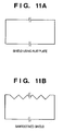
- the present invention employs a sawtoothed shield shown in Fig. 11B.
- the sawtoothed shield allows positions used to shield inspection light to exist within the sawtooth depth while suppressing the influence of diffraction light. This makes it possible to suppress a variation in shielding positions.
- Fig. 14 is a view illustrating a semiconductor device manufacturing exposure apparatus in which the particle inspection apparatus according to the above embodiment is mounted.
- the particle inspection apparatus As shown in Fig. 14, the particle inspection apparatus according to this embodiment is installed near the exposure apparatus to have an inspection table 6 on which a reticle 1 (pellicle 2) before exposure is placed.
- the particle inspection apparatus causes detectors 3 and 4 and inspection light forming unit 7 to scan in the x direction, thereby detecting the presence/absence of a particle. If a particle is absent as a result of the particle inspection process, the reticle 1 is transported from the particle inspection apparatus onto a reticle stage 102 by a transport robot (not shown).
- the exposure apparatus includes an illumination apparatus 101 which illuminates exposure light, the reticle stage 102 which holds/moves a reticle, a projection optical system 103, and a wafer stage 104 which holds/moves a wafer.
- the exposure apparatus projects and forms by exposure a circuit pattern formed on a reticle onto a wafer (substrate).
- the projection exposure method can employ the step & repeat scheme or step & scan scheme.
- the illumination apparatus 101 illuminates a reticle on which a circuit pattern is formed, and includes a light source unit and illumination optical system.
- the light source unit uses, for example, a laser as a light source.
- a laser there is available an ArF excimer laser having a wavelength of 193 nm, a KrF excimer laser having a wavelength of 248 nm, or an F2 excimer laser having a wavelength of about 153 nm.
- the laser type is not limited to an excimer laser, and, for example, a YAG laser may be used.
- the number of lasers is not limited.
- a beam shaping optical system which shapes a parallel light beam from the laser light source into a desired beam shape, or an incoherent optical system which converts a coherent laser beam into an incoherent one is preferably used.
- a light source usable as the light source unit is not limited to a laser, and one or a plurality of mercury lamps or xenon lamps can be used.
- the illumination optical system illuminates a reticle, and includes a lens, mirror, light integrator, and field stop.
- the projection optical system 103 there is available an optical system including only a plurality of lens elements, an optical system including a plurality of lens elements and at least one concave mirror (catadioptric optical system), an optical system including a plurality of lens elements and at least one diffraction optical element such as a kinoform, or an optical system of total reflection mirror type.
- Such an exposure apparatus can be used to manufacture a semiconductor device such as a semiconductor integrated circuit, or a device such as a micromachine or thin-film magnetic head on which a micropattern is formed.
- Fig. 15 shows the manufacturing flow of a microdevice (semiconductor chip such as an IC or LSI, a liquid crystal panel, a CCD, a thin-film magnetic head, a micromachine, or the like).
- a semiconductor device circuit is designed.
- exposure control data creation exposure control data of the exposure apparatus is created based on the designed circuit pattern.
- step S3 wafer fabrication
- a wafer is fabricated by using a material such as silicon.
- step S4 wafer process
- a pre-process an actual circuit is formed on the wafer by lithography using the wafer and the exposure apparatus which has received the prepared exposure control data.
- Step S5 (assembly) called a post-process is the step of forming a semiconductor chip by using the wafer fabricated in step S4, and includes an assembly process (dicing and bonding) and packaging process (chip encapsulation).
- step S6 the semiconductor device manufactured in step S5 undergoes inspections such as an operation confirmation test and durability test. After these steps, the semiconductor device is completed and shipped (step S7).
- Fig. 16 shows the detailed flow of the wafer process.
- step S11 oxidation
- step S12 CVD
- step S13 electrode formation
- step S14 ion implantation
- ions are implanted in the wafer.
- step S15 resist process
- step S16 exposure
- step S18 etching
- step S19 resist removal
- the manufacturing method of the embodiment can manufacture at low cost a high-integration-degree semiconductor device which is difficult to manufacture by the prior art.
- the present invention can be applied to various precision processing apparatuses and various precision measurement apparatuses, in addition to semiconductor exposure apparatuses used to manufacture a semiconductor element, liquid-crystal display device, and the like.
- the present invention is effective to detect a particle on the inspection surface of a processing target or measurement target.
Abstract
Description
- The present invention relates to a particle inspection technique for inspecting the surface of an object for a particle, and an exposure technique using the particle inspection technique.
- In manufacturing a semiconductor element formed from a micropattern such as an LSI or VLSI, a reduction projection exposure apparatus is used to form by exposure a circuit pattern drawn on a reticle or mask by reducing and projecting it onto a wafer coated with a photosensitive agent. Along with an increase in mounting density of a semiconductor element, further micropatterning is required. The exposure apparatus takes a measure to implement micropatterning at the same time as the development of a resist process.
- Unfortunately, if a particle such as dust adheres to the substrate surface in pattern transfer, the particle is also transferred in the circuit pattern, resulting in a large decrease in manufacturing yield of an IC or LSI. For this reason, a mask or reticle generally has a pattern protective member called a pellicle consisting of transparent thin films which are made of cellulose nitrate and have a thickness of about 1 µm. This prevents a particle such as dust from adhering to the reticle pattern surface.
- If a particle adheres to the reticle blank surface or pellicle surface spaced apart from the reticle pattern surface, the particle is not transferred onto a wafer. However, a defocused image of the particle adhering to the above-mentioned surface may possibly be transferred, so the light amount varies on the wafer, resulting in unsatisfactory exposure.
- To solve this problem, the presence/absence of a particle on a reticle (blank surface) or pellicle must inevitably be detected before and/or after exposure in manufacturing an IC or LSI. A general method takes advantage of a nature in which a particle diffuses light isotropically. For example, parallel light beams are collectively applied to the inspection surface region obliquely from above. Scattered light from a particle is applied onto a one-dimensional image sensor (sensor array) by a microlens array of refractive index distribution type to image the particle. Then, the inspection surface is inspected to detect the presence/absence of a particle (to be referred to as a foreign particle or contaminant hereinafter).
- Fig. 12 is a view showing an outline of the structure of a particle inspection apparatus. A
reticle 1 and pellicle 2 (not shown) as inspection objects are held on an inspection table 6. An inspection light forming unit (to be also referred to as an irradiator) 7 forms inspection light and irradiates an inspection object with it. A reticle-side detector 3 faces thereticle 1 and detects inspection light applied to thereticle 1. A pellicle-side detector 4 faces thepellicle 2 and detects inspection light applied to thepellicle 2. - The inspection
light forming unit 7 scans the reticle-side detector 3 and pellicle-side detector 4 in the direction of an arrow (x direction) with respect to an inspection object to inspect the entire surface of the inspection object for a particle. - Fig. 13 is a side view of Fig. 12 when viewed from the x direction, and a structure on the
pellicle 2 side is omitted. - Referring to Fig. 13, the inspection
light forming unit 7 collectively appliesinspection light beams 14a as parallel light beams to thereticle 1. The applied inspection light beams are detected by thedetector 3 to detect a particle. - At this time, part of the
inspection light beams 14a emitted from the inspectionlight forming unit 7 comes from anedge portion 1a (end face portion) of thereticle 1 and enters thereticle 1. The entered inspection light is sometimes diffracted by apattern 20 drawn on thereticle 1 to generate adiffraction light beam 21. When thediffraction light beam 21 strikes thedetector 3, it is erroneously detected as scattered light from a particle. This disables accurate particle detection. - As disclosed in
Japanese Patent Laid-Open No. 58-79240 - The present invention has been made in consideration of the above background, and has as its exemplary object to provide a novel technique for realizing particle inspection with high accuracy.
- In order to achieve the above object, according to the present invention, there is provided an inspection apparatus for inspecting a surface of an object for a particle, comprising: an irradiator configured to irradiate the surface with inspection light; a first detector configured to detect light scattered at the surface; and a shield configured to limit an irradiation region of the inspection light emitted by the irradiator within a limited region of the surface.
- According to the present invention, there is also provided an inspection method of inspecting a surface of an object for a particle, comprising: an emission step of emitting inspection light; a shield step of shielding the inspection light with a shield to limit an irradiation region of the emitted inspection light within a limited region of the surface; and a first detection step of detecting light scattered at the surface irradiated with the shielded inspection light.
- The present invention can also be applied to an exposure apparatus for exposing a substrate to light via a reticle having the above inspection apparatus, and a method of manufacturing a device, comprising steps of: exposing a substrate to light via a reticle using an exposure apparatus as defined above; developing the exposed substrate; and processing the developed substrate to manufacture the device.
- The present invention makes it possible to provide a novel technique for realizing particle inspection with high accuracy.
- Other objects and advantages besides those discussed above shall be apparent to those skilled in the art from the description of a preferred embodiment of the invention which follows. In the description, reference is made to accompanying drawings, which form apart thereof, and which illustrate an example of the invention. Such example, however, is not exhaustive of the various embodiments of the invention, and therefore reference is made to the claims which follow the description for determining the scope of the invention.
-
- Fig. 1 is a view showing an outline of the structure of a particle inspection apparatus according to the first embodiment of the present invention;
- Fig. 2 is a side view of Fig. 1 when viewed from the x direction;
- Fig. 3 is a side view showing the positional relationship between an inspection light beam and a shield when viewed from the x direction;
- Fig. 4 is a view showing a particle inspection apparatus as a modification of the first embodiment;
- Fig. 5 is a side view showing an outline of the structure of a particle inspection apparatus according to the second embodiment when viewed from the x direction;
- Fig. 6 is a side view showing an outline of the structure of a particle inspection apparatus according to the third embodiment when viewed from the x direction;
- Fig. 7 is a side view showing an outline of the structure of a particle inspection apparatus according to the fourth embodiment when viewed from the x direction;
- Fig. 8 is a graph showing the illuminance distribution of inspection light along the direction of detection on an inspection surface;
- Figs. 9A and 9B are graphs showing the illuminance distribution of inspection light along the direction of detection on the inspection surface;
- Fig. 10 is a view showing the positional relationship among an inspection light beam, detector, and shield;
- Figs. 11A and 11B are views showing the shapes of shields;
- Fig. 12 is a view showing a particle inspection apparatus;
- Fig. 13 is a side view of Fig. 12 when viewed from the x direction;
- Fig. 14 is a view showing an application example to an exposure apparatus;
- Fig. 15 is a flowchart showing the manufacturing flow of a microdevice; and
- Fig. 16 is a flowchart for explaining a wafer process.
- Embodiments of the present invention will be described below in detail with reference to the accompanying drawings.
- Note that the embodiments to be described hereinafter are examples as implementation means of the present invention, and should be appropriately modified or changed in accordance with various conditions and the structure of an apparatus to which the present invention is applied.
- Fig. 1 is a view showing an outline of the structure of a particle inspection apparatus according to the first embodiment of the present invention.
- As shown in Fig. 1, a laser beam emitted from a
laser diode 8 is converted into a parallel light beam by acollimator lens 9. The collimated laser beam is split by a beam splitter (half mirror) 10a into two light beams A and B having almost the same intensity with each other. A transmitted light beam B transmitted through thebeam splitter 10a is applied to abeam splitter 10b. A reflected light beam A reflected by thebeam splitter 10b is applied to acube corner reflector 18. - The
cube corner reflector 18 is arranged to be shifted from thebeam splitters beam splitter 10b. After that, light beams Aa and Ba emitted from thebeam splitter 10b in the x direction become parallel with each other, and form a shape in which the centers of the two light beams are spaced by a distance L. - Since the
beam splitter 10b is a half mirror, it emits light beams Ab and Bb in the z direction, the centers of which are spaced by the distance L. - Combined light beams (Aa + Ba) and (Ab + Bb) are applied, as
inspection light beams reticle 1 and the lower surface (inspection surface) of apellicle 2, respectively. Theinspection light beams beam splitters reticle 1 andpellicle 2 at a predetermined angle by reflectors (mirrors) 11, 12, and 13, thus forming almost uniform slit light on the inspection surfaces. - As descried with reference to Fig. 12,
detectors light forming unit 7 are scanned in the x direction with respect to thereticle 1 andpellicle 2 to inspect the entire inspection surface of the inspection object for a particle. If aparticle 17 is present in the irradiation region of inspection light, scattered light is generated from the particle. The scattered light is imaged on aline sensor 16 bylens array 15 arranged along the irradiation region of inspection light. - A characteristic feature of this embodiment is that a shield (plate) 5 is so arranged as to limit the irradiation range of inspection light such that the
inspection light 14a is prevented from striking the edge portion of the inspection object. - Fig. 2 is a side view of Fig. 1 when viewed from the x direction, and a structure on the
pellicle 2 side is omitted. - As shown in Fig. 2, the
shield 5 is arranged between thereticle 1 and inspectionlight forming unit 7. Theshield 5 serves to shield inspection light over the entire inspection surface when it moves by scanning together with the inspectionlight forming unit 7. - Of
inspection light beams 14a emitted from the inspectionlight forming unit 7, aninspection light beam 14a applied to anedge portion 1a of thereticle 1 is shielded by theshield 5 so as not to generate a diffractedlight beam 21 due to apattern 20 drawn on thereticle 1, as described with reference to Fig. 13. More specifically, since the sensitivity of a detector to the diffractedlight beam 21 can be set low, the intensity (light amount) of inspection light can be relatively high. This makes it possible to detect scattered light by a smaller particle, thus realizing highly accurate particle inspection. - Fig. 3 is a side view showing the positional relationship between the
inspection light beam 14a and theshield 5 when viewed from the x direction. - Referring to Fig. 3, let X be a necessary inspection region, and N be a non-irradiation region necessary not to irradiate the
end face 1a of thereticle 1. Letting A be the distance from theend face 1a to theshield 5, Z be the height from an inspection table 6, h be the thickness of thereticle 1, and a be the angle [deg] of the incidentinspection light beam 14a with respect to the reticle surface, theshield 5 is arranged to satisfy a condition to be obtained by a geometrical relationship:
- In this embodiment, the
shield 5 is arranged on the inspectionlight forming unit 7 to be scanned. However, theshield 5 may be arranged on the inspection table 6 to extend over the scanning direction, as illustrated in Fig. 4. The edge portion of theshield 5 is more preferably sharp like the edge of a knife, and should be closer to thereticle 1. A low-reflecting member is more preferable to reduce flare from the shield. - Note that the
shield 5 of theinspection light 14a applied to thereticle 1 has been described in this embodiment. However, theshield 5 can be similarly used for the inspection light 14b applied to thepellicle 2. - Fig. 5 is a side view showing an outline of the structure of a particle inspection apparatus according to the second embodiment when viewed from the x direction, and a structure on the
pellicle 2 side is omitted. - In the second embodiment, a
position measurement mechanism 24 is arranged to measure the position (height to a detector 3) of the inspection surface of areticle 1. - As shown in Fig. 5, a
shield 5 is attached to an inspectionlight forming unit 7 through aposition adjustment mechanism 23 consisting of actuators such as a motor. Acontroller 25 drives theposition adjustment mechanism 23 to control the position and orientation (with respect to the detector and edge portion) of theshield 5. Information about the position of the inspection surface measured by theposition measurement mechanism 24 is sent to thecontroller 25. Then, the position of theshield 5 is corrected by driving theposition adjustment mechanism 23 such that the positions of the inspection surface andshield 5 satisfy the above condition. - The
position measurement mechanism 24 moves by scanning together with the inspectionlight forming unit 7, thereby inspecting a particle while correcting the position of theshield 5. Note that theshield 5 may be movable in the horizontal direction instead of the vertical direction to execute position adjustment. If the angle of an incidentinspection light beam 14a with respect to the reticle surface is acute (small), theinspection light beam 14a is less sensitive to position adjustment in the horizontal direction than in the vertical direction (that is, a variation in intensities ofinspection light beams 14a is small in the horizontal direction). This makes it possible to simplify the structure of theposition adjustment mechanism 23. Thereticle 1 may be relatively displaced with respect to theshield 5 by using a stage apparatus or the like. - Fig. 6 is a side view showing an outline of the structure of a particle inspection apparatus according to the third embodiment when viewed from the x direction, and a structure on the
pellicle 2 side is omitted. - In the second embodiment, the
position measurement mechanism 24 for measuring the position of an inspection surface is arranged to correct the position of theshield 5 in accordance with the height of the inspection surface. By contrast, in this embodiment, adetector 3 detects inspection light which diffuses on anend face 1a of areticle 1, and the position of ashield 5 is adjusted to prevent aninspection light beam 14a from striking the edge portion of theend face 1a. - As shown in Fig. 6, a
field stop 26 is arranged between thedetector 3 and inspection surface to limit an inspection region. This prevents thedetector 3 from detecting inspection light beams 28 which scatter on the edge portion of theend face 1a. In this embodiment, anaperture 27 is separately formed near the end face to detect the inspection light beams 28 which scatter on the edge portion of theend face 1a. Theaperture 27 allows a line sensor (not shown) arranged in thedetector 3 to detect scattered light on the edge portion. The detected light amount information is sent to a controller (not shown) to cause aposition adjustment mechanism 23 to correct the position of theshield 5. Thereticle 1 may be relatively displaced with respect to theshield 5. - The intensity of scattered light on the edge portion is higher than that of scattered light by a particle. For this reason, it is possible to adjust the size of the
aperture 27 to limit the incident light amount, thereby preventing saturation of charges accumulated in a sensor. - Fig. 7 is a side view showing an outline of the structure of a particle inspection apparatus according to the fourth embodiment when viewed from the x direction, and a structure on the
pellicle 2 side is omitted. - Referring to Fig. 7, an
inspection light beam 29 which comes from the edge portion of anend face 1a of areticle 1 and enters thereticle 1 is repeatedly subjected to total reflection in thereticle 1, and emitted outside from an opposingface 1b. At this time, if aninspection light beam 14a is not applied to the edge portion, the intensity of light emitted from the opposingface 1b decreases. In this embodiment, therefore, adetector 30 is arranged on the opposingface 1b to detect the emitted light amount. Hence, the position of ashield 5 is corrected to prevent theinspection light beam 14a from entering thereticle 1. - More specifically, the
detector 30 is arranged on the opposingface 1b of thereticle 1 to detect the amount of theinspection light beam 29 transmitted through the interior of thereticle 1. Information about the light amount detected by thedetector 30 is sent to a controller (not shown) to cause aposition adjustment mechanism 23 to correct the position of theshield 5. Thereticle 1 may be relatively displaced with respect to theshield 5. - According to this embodiment, it is possible to determine, in accordance with the light amount detected by the detector, whether the
inspection light beam 14a has entered from the edge portion. Hence, the validity of a particle inspection result can be determined in accordance with the light amount to obtain a highly reliable detection result. - Fig. 8 is a graph showing the illuminance distribution of inspection light along the direction of detection on an inspection surface.
- Fig. 8 shows an illuminance distribution in which an inspection region is made uniform by an inspection light forming unit.
- According to the present invention, a shield is so arranged as to limit the irradiation range of inspection light such that inspection light is prevented from striking an edge portion.
- When a flat shield like Fig. 11A shields inspection light, diffraction light is generated from a
shield 5 and illuminance varies in an inspection surface, as shown in Fig. 9A. - Diffraction light generated by a shield has a high intensity in a direction normal to the shield. When the
shield 5 is arranged such that a normal to theshield 5 is not parallel to an inclination β [deg] of adetector 3 as shown in Fig. 10, the influence of the diffraction light can be reduced. - As described with reference to Fig. 1, an inspection light beam is emitted from a semiconductor laser such as a laser diode serving as a light source, and collimated by a
collimator lens 9 to have an elliptic sectional shape as shown in Fig. 10. If theshield 5 is arranged obliquely with respect to the inspection light beam, a region used to shield the inspection light beam varies depending on the minor-axis direction of the inspection light beam. As a result, the light amount of the shield slightly varies on an inspection surface. For this reason, there is a possibility that the edge portion cannot be shielded effectively. - To solve this problem, the present invention employs a sawtoothed shield shown in Fig. 11B. The sawtoothed shield allows positions used to shield inspection light to exist within the sawtooth depth while suppressing the influence of diffraction light. This makes it possible to suppress a variation in shielding positions.
- When the sawtooth angle is set to be almost perpendicular to the inclination direction of the
detector 3, interference can be prevented effectively. In the example shown in Fig. 11B, sawteeth having a depth of 0.15 mm are formed at an angle of 45°. - Fig. 14 is a view illustrating a semiconductor device manufacturing exposure apparatus in which the particle inspection apparatus according to the above embodiment is mounted.
- As shown in Fig. 14, the particle inspection apparatus according to this embodiment is installed near the exposure apparatus to have an inspection table 6 on which a reticle 1 (pellicle 2) before exposure is placed. The particle inspection apparatus causes
detectors light forming unit 7 to scan in the x direction, thereby detecting the presence/absence of a particle. If a particle is absent as a result of the particle inspection process, thereticle 1 is transported from the particle inspection apparatus onto areticle stage 102 by a transport robot (not shown). - The exposure apparatus according to this embodiment includes an
illumination apparatus 101 which illuminates exposure light, thereticle stage 102 which holds/moves a reticle, a projectionoptical system 103, and awafer stage 104 which holds/moves a wafer. The exposure apparatus projects and forms by exposure a circuit pattern formed on a reticle onto a wafer (substrate). The projection exposure method can employ the step & repeat scheme or step & scan scheme. - The
illumination apparatus 101 illuminates a reticle on which a circuit pattern is formed, and includes a light source unit and illumination optical system. The light source unit uses, for example, a laser as a light source. As the laser, there is available an ArF excimer laser having a wavelength of 193 nm, a KrF excimer laser having a wavelength of 248 nm, or an F2 excimer laser having a wavelength of about 153 nm. However, the laser type is not limited to an excimer laser, and, for example, a YAG laser may be used. Also, the number of lasers is not limited. If a laser is used as the light source, a beam shaping optical system which shapes a parallel light beam from the laser light source into a desired beam shape, or an incoherent optical system which converts a coherent laser beam into an incoherent one is preferably used. A light source usable as the light source unit is not limited to a laser, and one or a plurality of mercury lamps or xenon lamps can be used. The illumination optical system illuminates a reticle, and includes a lens, mirror, light integrator, and field stop. - As the projection
optical system 103, there is available an optical system including only a plurality of lens elements, an optical system including a plurality of lens elements and at least one concave mirror (catadioptric optical system), an optical system including a plurality of lens elements and at least one diffraction optical element such as a kinoform, or an optical system of total reflection mirror type. - Such an exposure apparatus can be used to manufacture a semiconductor device such as a semiconductor integrated circuit, or a device such as a micromachine or thin-film magnetic head on which a micropattern is formed.
- An embodiment of a device manufacturing method using the exposure apparatus described above will be described next.
- Fig. 15 shows the manufacturing flow of a microdevice (semiconductor chip such as an IC or LSI, a liquid crystal panel, a CCD, a thin-film magnetic head, a micromachine, or the like). In step S1 (circuit design), a semiconductor device circuit is designed. In step S2 (exposure control data creation), exposure control data of the exposure apparatus is created based on the designed circuit pattern. In step S3 (wafer fabrication), a wafer is fabricated by using a material such as silicon. In step S4 (wafer process) called a pre-process, an actual circuit is formed on the wafer by lithography using the wafer and the exposure apparatus which has received the prepared exposure control data. Step S5 (assembly) called a post-process is the step of forming a semiconductor chip by using the wafer fabricated in step S4, and includes an assembly process (dicing and bonding) and packaging process (chip encapsulation). In step S6 (inspection), the semiconductor device manufactured in step S5 undergoes inspections such as an operation confirmation test and durability test. After these steps, the semiconductor device is completed and shipped (step S7).
- Fig. 16 shows the detailed flow of the wafer process. In step S11 (oxidation), the wafer surface is oxidized. In step S12 (CVD), an insulating film is formed on the wafer surface. In step S13 (electrode formation), an electrode is formed on the wafer by vapor deposition. In step S14 (ion implantation), ions are implanted in the wafer. In step S15 (resist process), a photosensitive agent is applied to the wafer. In step S16 (exposure), the above-mentioned exposure apparatus exposes the wafer to form a circuit pattern. In step S17 (development), the exposed wafer is developed. In step S18 (etching), portions other than the developed resist image are etched. In step S19 (resist removal), any unnecessary resist remaining after etching is removed. These steps are repeated to form multiple circuit patterns on the wafer.
- The manufacturing method of the embodiment can manufacture at low cost a high-integration-degree semiconductor device which is difficult to manufacture by the prior art.
- The present invention can be applied to various precision processing apparatuses and various precision measurement apparatuses, in addition to semiconductor exposure apparatuses used to manufacture a semiconductor element, liquid-crystal display device, and the like. The present invention is effective to detect a particle on the inspection surface of a processing target or measurement target.
- As many apparently widely different embodiments of the present invention can be made without departing from the spirit and scope thereof, it is to be understood that the invention is not limited to the specific embodiments thereof except as defined in the appended claims.
Claims (13)
- An inspection apparatus for inspecting a surface of an object for a particle, said apparatus comprising:an irradiator configured to irradiate the surface with inspection light;a first detector configured to detect light scattered at the surface; anda shield configured to limit an irradiation region of the inspection light emitted by said irradiator within a limited region of the surface.
- An apparatus according to claim 1, further comprising:a position measurement mechanism configured to measure a position of the surface; anda relative position adjustment mechanism configured to adjust relative position between said shield and the surface based on information of the measured position of the surface.
- An apparatus according to claim 1, further comprising:a second detector configured to detect light scattered at an edge of the object; anda relative position adjustment mechanism configured to adjust relative position between said shield and the surface based on information of the detected scattered light.
- An apparatus according to claim 1, further comprising:a second detector configured to detect light transmitted through the object; anda relative position adjustment mechanism configured to adjust relative position between said shield and the surface based on information of the detected transmitted light.
- An apparatus according to any one of claims 1 to 4, wherein said shield includes a sawtooth edge.
- An inspection method of inspecting a surface of an object for a particle, said method comprising:an emission step of emitting inspection light;a shield step of shielding the inspection light with a shield to limit an irradiation region of the emitted inspection light within a limited region of the surface; anda first detection step of detecting light scattered at the surface irradiated with the shielded inspection light.
- A method according to claim 6, further comprising:a position measurement step of measuring a position of the surface; anda relative position adjustment step of adjusting relative position between the shield and the surface based on information of the measured position of the surface.
- A method according to claim 6, further comprising:a second detection step of detecting light scattered at an edge of the object; anda relative position adjustment step of adjusting relative position between the shield and the surface based on information of the detected scattered light.
- A method according to claim 6, further comprising:a second detection step of detecting light transmitted through the object; anda relative position adjustment step of adjusting relative position between the shield and the surface based on information of the detected transmitted light.
- A method according to any one of claims 6-9, wherein the shield includes a sawtooth edge.
- An exposure apparatus for exposing a substrate to light via a reticle, said apparatus comprising:an inspection apparatus as defined in claim 1 for inspecting a surface of an object for a particle.
- An apparatus according to claim 11, wherein said inspection apparatus is configured to inspect a surface of at least one of the reticle and a pellicle for a particle.
- A method of manufacturing a device, said method comprising steps of:exposing a substrate to light via a reticle using an exposure apparatus as defined in claim 11 or 12;developing the exposed substrate; andprocessing the developed substrate to manufacture the device.
Applications Claiming Priority (1)
| Application Number | Priority Date | Filing Date | Title |
|---|---|---|---|
| JP2005122945A JP4217692B2 (en) | 2005-04-20 | 2005-04-20 | Foreign matter inspection apparatus, foreign matter inspection method, exposure apparatus, and device manufacturing method |
Publications (1)
| Publication Number | Publication Date |
|---|---|
| EP1715329A1 true EP1715329A1 (en) | 2006-10-25 |
Family
ID=36691897
Family Applications (1)
| Application Number | Title | Priority Date | Filing Date |
|---|---|---|---|
| EP06003289A Withdrawn EP1715329A1 (en) | 2005-04-20 | 2006-02-17 | Particle inspection apparatus and method, exposure apparatus, and device manufacturing method |
Country Status (4)
| Country | Link |
|---|---|
| US (1) | US7388659B2 (en) |
| EP (1) | EP1715329A1 (en) |
| JP (1) | JP4217692B2 (en) |
| KR (1) | KR100740601B1 (en) |
Cited By (1)
| Publication number | Priority date | Publication date | Assignee | Title |
|---|---|---|---|---|
| EP2093611A3 (en) * | 2008-02-20 | 2012-06-27 | Canon Kabushiki Kaisha | Particle inspection apparatus, exposure apparatus, and device manufacturing method |
Families Citing this family (7)
| Publication number | Priority date | Publication date | Assignee | Title |
|---|---|---|---|---|
| JP2008032621A (en) * | 2006-07-31 | 2008-02-14 | Hitachi High-Technologies Corp | Surface inspecting apparatus and method for same |
| JP2010032265A (en) * | 2008-07-25 | 2010-02-12 | Canon Inc | Inspection device of foreign matter, exposure system and device manufacturing method |
| JP5510409B2 (en) * | 2011-08-01 | 2014-06-04 | トヨタ自動車株式会社 | Unnecessary varnish inspection device and inspection method |
| JP6270288B2 (en) * | 2016-01-29 | 2018-01-31 | レーザーテック株式会社 | Inspection apparatus, inspection method, contamination prevention structure, and exposure apparatus |
| JP7292842B2 (en) * | 2018-09-21 | 2023-06-19 | キヤノン株式会社 | Foreign Matter Inspection Apparatus, Exposure Apparatus, and Article Manufacturing Method |
| JP7170491B2 (en) * | 2018-10-12 | 2022-11-14 | キヤノン株式会社 | Foreign matter detection device, exposure device, and article manufacturing method |
| CN114077163B (en) * | 2020-08-14 | 2023-03-31 | 长鑫存储技术有限公司 | Mask conveying device and exposure system |
Citations (10)
| Publication number | Priority date | Publication date | Assignee | Title |
|---|---|---|---|---|
| JPS58139113A (en) * | 1982-02-12 | 1983-08-18 | Ricoh Co Ltd | Iris plate for exposure device |
| US4831274A (en) * | 1986-07-28 | 1989-05-16 | Canon Kabushiki Kaisha | Surface inspecting device for detecting the position of foreign matter on a substrate |
| JPH03217843A (en) * | 1990-01-24 | 1991-09-25 | Hitachi Ltd | Foreign matter inspecting device |
| US5365330A (en) * | 1991-11-27 | 1994-11-15 | Nikon Corporation | Foreign particle inspection apparatus |
| US5473426A (en) * | 1993-03-05 | 1995-12-05 | Nikon Corporation | Defect inspection apparatus |
| US5585918A (en) * | 1994-06-28 | 1996-12-17 | Canon Kabushiki Kaisha | Foreign particle inspecting system |
| US5652657A (en) * | 1994-06-06 | 1997-07-29 | Canon Kabushiki Kaisha | Inspection system for original with pellicle |
| US6313913B1 (en) * | 1998-11-26 | 2001-11-06 | Nikon Corporation | Surface inspection apparatus and method |
| JP2004053972A (en) * | 2002-07-22 | 2004-02-19 | Nikon Corp | Apparatus for foreign matter inspection, exposure device mounted with the same device, and exposure method using the same exposure device |
| US6778285B1 (en) * | 2000-01-21 | 2004-08-17 | Wafertech, Inc. | Automatic in situ pellicle height measurement system |
Family Cites Families (9)
| Publication number | Priority date | Publication date | Assignee | Title |
|---|---|---|---|---|
| US3799679A (en) * | 1972-06-27 | 1974-03-26 | Ppg Industries Inc | Glass distortion scanning system |
| JPS5879240A (en) | 1981-11-06 | 1983-05-13 | Nippon Kogaku Kk <Nikon> | Foreign matter detector |
| US4669875A (en) * | 1982-11-04 | 1987-06-02 | Hitachi, Ltd. | Foreign particle detecting method and apparatus |
| JPH0799324B2 (en) * | 1987-07-02 | 1995-10-25 | 富士写真フイルム株式会社 | Bonding inspection device |
| JPH0462457A (en) | 1990-07-02 | 1992-02-27 | Canon Inc | Surface state inspecting device |
| JP3259331B2 (en) * | 1992-05-29 | 2002-02-25 | キヤノン株式会社 | Surface condition inspection device |
| JPH06258237A (en) | 1993-03-05 | 1994-09-16 | Nikon Corp | Defect inspection device |
| US5581348A (en) * | 1993-07-29 | 1996-12-03 | Canon Kabushiki Kaisha | Surface inspecting device using bisected multi-mode laser beam and system having the same |
| JP2962972B2 (en) | 1993-07-29 | 1999-10-12 | キヤノン株式会社 | Surface condition inspection apparatus and exposure apparatus having the same |
-
2005
- 2005-04-20 JP JP2005122945A patent/JP4217692B2/en not_active Expired - Fee Related
-
2006
- 2006-02-17 EP EP06003289A patent/EP1715329A1/en not_active Withdrawn
- 2006-02-23 US US11/359,431 patent/US7388659B2/en not_active Expired - Fee Related
- 2006-03-09 KR KR1020060022026A patent/KR100740601B1/en active IP Right Grant
Patent Citations (10)
| Publication number | Priority date | Publication date | Assignee | Title |
|---|---|---|---|---|
| JPS58139113A (en) * | 1982-02-12 | 1983-08-18 | Ricoh Co Ltd | Iris plate for exposure device |
| US4831274A (en) * | 1986-07-28 | 1989-05-16 | Canon Kabushiki Kaisha | Surface inspecting device for detecting the position of foreign matter on a substrate |
| JPH03217843A (en) * | 1990-01-24 | 1991-09-25 | Hitachi Ltd | Foreign matter inspecting device |
| US5365330A (en) * | 1991-11-27 | 1994-11-15 | Nikon Corporation | Foreign particle inspection apparatus |
| US5473426A (en) * | 1993-03-05 | 1995-12-05 | Nikon Corporation | Defect inspection apparatus |
| US5652657A (en) * | 1994-06-06 | 1997-07-29 | Canon Kabushiki Kaisha | Inspection system for original with pellicle |
| US5585918A (en) * | 1994-06-28 | 1996-12-17 | Canon Kabushiki Kaisha | Foreign particle inspecting system |
| US6313913B1 (en) * | 1998-11-26 | 2001-11-06 | Nikon Corporation | Surface inspection apparatus and method |
| US6778285B1 (en) * | 2000-01-21 | 2004-08-17 | Wafertech, Inc. | Automatic in situ pellicle height measurement system |
| JP2004053972A (en) * | 2002-07-22 | 2004-02-19 | Nikon Corp | Apparatus for foreign matter inspection, exposure device mounted with the same device, and exposure method using the same exposure device |
Non-Patent Citations (3)
| Title |
|---|
| PATENT ABSTRACTS OF JAPAN vol. 007, no. 256 (P - 236) 15 November 1983 (1983-11-15) * |
| PATENT ABSTRACTS OF JAPAN vol. 015, no. 503 (P - 1290) 19 December 1991 (1991-12-19) * |
| PATENT ABSTRACTS OF JAPAN vol. 2003, no. 12 5 December 2003 (2003-12-05) * |
Cited By (1)
| Publication number | Priority date | Publication date | Assignee | Title |
|---|---|---|---|---|
| EP2093611A3 (en) * | 2008-02-20 | 2012-06-27 | Canon Kabushiki Kaisha | Particle inspection apparatus, exposure apparatus, and device manufacturing method |
Also Published As
| Publication number | Publication date |
|---|---|
| KR100740601B1 (en) | 2007-07-18 |
| US20060238752A1 (en) | 2006-10-26 |
| US7388659B2 (en) | 2008-06-17 |
| JP4217692B2 (en) | 2009-02-04 |
| JP2006301303A (en) | 2006-11-02 |
| KR20060110751A (en) | 2006-10-25 |
Similar Documents
| Publication | Publication Date | Title |
|---|---|---|
| US7388659B2 (en) | Particle inspection apparatus and method, exposure apparatus, and device manufacturing method | |
| US7791718B2 (en) | Measurement method, exposure method, and device manufacturing method | |
| JP4315455B2 (en) | Exposure apparatus and device manufacturing method | |
| JP3253177B2 (en) | Surface condition inspection device | |
| US7339662B2 (en) | Exposure apparatus and a device manufacturing method using the same | |
| JP4724470B2 (en) | Exposure method | |
| EP3096346A1 (en) | Exposure apparatus, exposure method, and device manufacturing method | |
| US6124922A (en) | Exposure device and method for producing a mask for use in the device | |
| US8339568B2 (en) | Foreign particle inspection apparatus, exposure apparatus, and method of manufacturing device | |
| US20050231703A1 (en) | Exposure apparatus, and device manufacturing method | |
| JP3874755B2 (en) | Method for determining stray radiation, lithographic projection apparatus | |
| US20100296074A1 (en) | Exposure method, and device manufacturing method | |
| JP3428705B2 (en) | Position detecting device and method of manufacturing semiconductor device using the same | |
| US8330949B2 (en) | Foreign substance inspection apparatus, exposure apparatus, and method of manufacturing device | |
| JP3368017B2 (en) | Position detecting device and method of manufacturing semiconductor device using the same | |
| JP2007256577A (en) | Foreign matter inspecting device, exposure device, and mask for light exposure | |
| JP2007173533A (en) | Exposure device, exposure method, and method for manufacturing device | |
| US20050128455A1 (en) | Exposure apparatus, alignment method and device manufacturing method | |
| US7936452B2 (en) | Inspection apparatus, exposure apparatus, and method of manufacturing device | |
| JP3420401B2 (en) | Position detecting apparatus and method, semiconductor exposure apparatus, and method of manufacturing semiconductor device | |
| JPH1154425A (en) | Position detector and manufacture of semiconductor element using the same | |
| JPH0429309A (en) | Thin film removal device |
Legal Events
| Date | Code | Title | Description |
|---|---|---|---|
| PUAI | Public reference made under article 153(3) epc to a published international application that has entered the european phase |
Free format text: ORIGINAL CODE: 0009012 |
|
| AK | Designated contracting states |
Kind code of ref document: A1 Designated state(s): AT BE BG CH CY CZ DE DK EE ES FI FR GB GR HU IE IS IT LI LT LU LV MC NL PL PT RO SE SI SK TR |
|
| AX | Request for extension of the european patent |
Extension state: AL BA HR MK YU |
|
| 17P | Request for examination filed |
Effective date: 20070425 |
|
| 17Q | First examination report despatched |
Effective date: 20070524 |
|
| AKX | Designation fees paid |
Designated state(s): AT BE BG CH CY CZ DE DK EE ES FI FR GB GR HU IE IS IT LI LT LU LV MC NL PL PT RO SE SI SK TR |
|
| STAA | Information on the status of an ep patent application or granted ep patent |
Free format text: STATUS: THE APPLICATION HAS BEEN WITHDRAWN |
|
| 18W | Application withdrawn |
Effective date: 20110222 |