EP1715236A1 - Releasable coupling for two conduits, comprising automatic bayonet locking means - Google Patents
Releasable coupling for two conduits, comprising automatic bayonet locking means Download PDFInfo
- Publication number
- EP1715236A1 EP1715236A1 EP06290440A EP06290440A EP1715236A1 EP 1715236 A1 EP1715236 A1 EP 1715236A1 EP 06290440 A EP06290440 A EP 06290440A EP 06290440 A EP06290440 A EP 06290440A EP 1715236 A1 EP1715236 A1 EP 1715236A1
- Authority
- EP
- European Patent Office
- Prior art keywords
- spigot
- locking
- angular
- ring
- rotation
- Prior art date
- Legal status (The legal status is an assumption and is not a legal conclusion. Google has not performed a legal analysis and makes no representation as to the accuracy of the status listed.)
- Withdrawn
Links
Images


Classifications
-
- F—MECHANICAL ENGINEERING; LIGHTING; HEATING; WEAPONS; BLASTING
- F16—ENGINEERING ELEMENTS AND UNITS; GENERAL MEASURES FOR PRODUCING AND MAINTAINING EFFECTIVE FUNCTIONING OF MACHINES OR INSTALLATIONS; THERMAL INSULATION IN GENERAL
- F16L—PIPES; JOINTS OR FITTINGS FOR PIPES; SUPPORTS FOR PIPES, CABLES OR PROTECTIVE TUBING; MEANS FOR THERMAL INSULATION IN GENERAL
- F16L37/00—Couplings of the quick-acting type
- F16L37/24—Couplings of the quick-acting type in which the connection is made by inserting one member axially into the other and rotating it to a limited extent, e.g. with bayonet action
Definitions
- the invention relates to a device for the removable coupling of the free ends of two fluid lines, which comprises two coaxial tips.
- an operator axially connects the male end into the socket, then it rotates the ring of the socket around its axis so as to accommodate the lugs in the notches associated.
- the operator first rotates the ring to unlock the coupling by releasing the lugs from their notches, and then axially moves the end pieces away from each other to uncouple them.
- both the coupling and uncoupling endcaps require the realization of an axial coupling or uncoupling operation, and a locking operation or unlocking by rotation of the ring.
- the invention proposes a device for coupling two pipes of the type previously described, in which there are provided rotational guiding means provided with elastic return means, which cause the automatic rotation of the first means of rotation. locking in the positive direction to cause the bayonet lock when the male end is axially fitted into the socket from its disassembled rear position to its position before coupled.
- FIG. 1 shows a free end 20 of a first duct which is located on the left of FIG. 1, and a free end 22 of a second duct which is located on the right of FIG.
- One of the lines is here connected to a reservoir (not shown) of cleaning fluid on board a motor vehicle while the other pipe is connected to a nozzle for cleaning a searchlight of the motor vehicle (not shown).
- the mouths of the two free ends 20, 22 are intended to be coupled to each other by means of a coupling device 24 to allow the nozzle to be fed with cleaning liquid.
- the mouths of the two free ends are arranged vis-à-vis one another so that they are coupled to each other along the axis "B" as shown in Figure 2.
- the device 24 for connecting the two ends 20, 22 comprises a first spigot 26, which is shown on the left in the figures, and a second spigot 28 which is shown on the right in the figures.
- the male end 26 comprises a body 30 of generally tubular shape coaxial with the axis "B" which is open at both ends.
- the male end 26 also comprises a ring 32 coaxial with the axis "B” and a cylindrical helical spring 34 coaxial with the axis "B".
- the female end 28 comprises here a single piece of tubular shape coaxial with the axis "B".
- Each tip 26, 28 is adapted to be adapted to the free end 20, 22 of the associated pipe.
- the body 30 of the spigot end 26 comprises a rear end portion 36 of cylindrical coupling which is intended to be inserted by force into the mouth of the free end 20 of the first conduit.
- the socket 28 has a cylindrical front end portion 38 for coupling which is intended to be forced into the mouth of the free end 22 of the second pipe.
- each end piece 26, 28 is sealingly attached to the associated conduit by means of a collar (not shown) which clamps the free end 20, 22 around the connecting end portion 36, 38.
- the tubular body 30 of the spigot end 26 comprises a cylindrical front end section which forms a bearing surface 40 which is intended to be fitted axially from rear to front in a sealed manner in the front coupling section 38 of the spigot.
- female end 28 in a coupled position of the spigot end 26 with the female end 28 in which the two lines 20, 22 are sealingly connected.
- the body 30 also comprises a central section 42 which is intended to receive the ring 32 in rotation.
- the diameter of the central section 42 is here substantially the same as that of the rear connecting end section 36 of the spigot end 26.
- An intermediate section 44 is interposed between the central section 42 and the front span 40.
- the intermediate section 44 has a smaller diameter than the diameters of the central section 42 and the front span 40.
- this intermediate section 44 is delimited axially by two shoulders rear radial 46 and front 48.
- the body 30 finally has a flange 50 which is interposed between the rear connecting end section 36 and the central section 42.
- the rear radial face 52 of the collar 50 is intended to form a stop for the annular edge of the mouth of the free end 20 during the insertion of the rear end section of connection 36 inside the end. free 20.
- the annular radial face 54 before the collar 50 has a toothed crown surface formed of a succession of "rising” slopes 55 and “descending” slopes 56 which are oriented tangentially to the body 30.
- "Upward” slope means a slope which is inclined from rear to front in the positive direction of rotation "R”, and by "downward” slope which is inclined from front to back always in the positive direction of rotation "R".
- the "downward" slopes 56 of the flange 50 are intended to form rotational guide ramps of the ring 32 for locking the coupling of the spigot 26 with the spigot 28 .
- the cylindrical peripheral face 58 of the collar 50 has fingers 60 which extend radially outwards.
- the fingers 60 are here ten in number and they are evenly distributed around the peripheral face 58.
- These fingers 60 are intended to cooperate with complementary indexing planes of the female end 28 which will be described later, in order to index the angular position of the body 30 about the axis "B" relative to the 28.
- the front radial face 62 of the fingers 60 is profiled in the form of a "V" whose tip is oriented towards the front.
- the ring 32 is rotatably mounted on the central portion 42 of the body 30 about the axis "B", and it is also slidably mounted relative to the body 30 in the axial direction "A" .
- the front end edge of the ring 32 has a flange 64 which extends radially inward, that is to say in the direction of the axis "B".
- the flange 64 is received around the intermediate portion 44 and axially between the shoulders 46, 48.
- the rear annular radial face 66 of the ring 32 has a toothed crown surface complementary to that of the front face 54 of the collar 50 of the body 30 so that the serrated rear face 66 of the ring 32 can be axially imbricated in the serrated front face 54 of the collar 50.
- the rear face 66 of the ring 32 comprises a succession of "rising” slopes 67 and “downward” slopes 68, as illustrated in FIG.
- the axial sliding of the ring 32 relative to the body 30 is limited forwardly by the contact of the collar 64 with the front shoulder 48, and, as shown in FIG. 3, towards the rear by the contact between the rear face 66 of the ring 32 and the front face 54 of the collar 50.
- the ring 32 also comprises lugs 70 which extend radially outwardly from the periphery of the ring 32.
- the lugs 70 are here five in number and they are evenly distributed around the periphery of the ring 32.
- the radial front face of the lugs 70 is shaped as a "V" whose tip is oriented towards the front.
- the radial distance between the axis "B" and the free end of the lugs 70 is greater than the radial distance between the axis "B" and the free end of the indexing fingers 60 of the collar 50.
- These lugs 70 form first axial locking means which have a locking function of the spigot 26 in its position coupled with the spigot 28.
- a front end section 72 of the ring 32 is intended to be introduced coaxially into a rear end section of the cylindrical spring 34.
- the ring 32 also comprises a central radial support shoulder 74 oriented towards the front on which the rear end of the spring 34 is intended to bear as shown in Figure 3.
- the spring 34 thus extends radially around the body 30 of the spigot end 26.
- the spring 34 is fixed to the ring 32 so that it is not accidentally separated from the male end 26.
- the female end 28 comprises a tubular cylindrical rear end portion 76 which coaxially extends rearward its connecting front end portion 38.
- the diameter of the rear end section 76 is substantially larger than the diameter of the front end section 38.
- the front end radial bottom 78 of the rear section 76 has a coaxial orifice 80 which opens into the front end of connection 38.
- the inside diameter of the rear end section 76 is large enough to accommodate the spigot end 26.
- the inside diameter of the front coupling end 38 is adapted to receive the forward bearing surface 40 of the spigot end 26 so as to sealingly connect the two free ends 20, 22 of the pipes.
- the forward bearing surface 40 of the male endpiece comprises an O-ring (not shown) which is intended to be interposed between the outer cylindrical face of the front bearing surface 40 and the inner cylindrical face of the front coupling portion 38 of the endpiece. female 26 to seal the connection.
- the contour of the end edge of the front span 40 comprises a chamfer 82 and the bottom 78 of the rear section 76 of the socket 28 has a peripheral zone 84 of the funnel-shaped coaxial orifice 80 to guide the front span 40 to the coaxial orifice 80.
- the rear section 76 of the socket 28 also includes a sleeve 86 which extends radially inwardly from the inner cylindrical face 88 of the rear section 76.
- the sleeve 86 is here integrally formed with the rear section 76.
- the sleeve 86 is shown in more detail in FIG.
- the inner cylindrical face 95 of the sleeve 86 has an internal diameter sufficient to allow the passage of the collar 50, but this internal diameter is not sufficient to allow the passage of the indexing fingers 60 of the collar 50.
- the front annular radial face of the sleeve 86 has notches 90 which are here five in number.
- each notch 90 is delimited upstream by a locking ramp 92 "downward” of front to back and downstream by a locking face 94 axially oriented perpendicular to a tangent direction.
- the bottom of the notch 90 is thus formed by the intersection of the rear end of the locking slope 92 and the locking face 94.
- Each notch 90 forms second axial locking means which is intended to receive a lug 70 of the ring 32 of the spigot 26 when the lug 70 is in an angular locking position, so as to axially lock the male end 26 in its position coupled with the female end 28.
- the inner cylindrical face 95 of the sleeve has axial grooves 96 which are interposed between the notches 90.
- the sleeve 86 here comprises five axial grooves 96.
- the front and rear ends of each groove 96 are open in the radial annular front and rear faces of the groove 96. sleeve 86.
- the axial grooves 96 are distributed around the sleeve 86 alternately with the notches 90, that is to say that the grooves 96 are not aligned axially with the notches 90.
- Each axial groove 96 is arranged such that a first front end of the associated locking ramp 92 is adjacent to the front end of the insertion groove 96.
- the axial grooves 96 are sufficiently deep to receive the lugs 70 in axial sliding along the sleeve 86 to the notches 90 to allow bayonet type locking of the male end 26 in position coupled with the female end 28.
- the axial grooves 96 thus form insertion grooves which are intended to allow the insertion of the lugs 70 to the notches 90. But these axial grooves 96 are also release grooves which allow the lugs 70 to be removed during the disengagement of the male end 26.
- the front annular radial face of the sleeve 86 also comprises release ramps 97 each of which is associated with a notch 90. More particularly, by rotating in the positive direction "R" around the front radial face of the sleeve 86, each release ramp 97 is arranged downstream of the associated notch 90 and has a plane inclined back and forth similar to that of the locking ramps 92. The rear upstream end of the release ramp 97 is adjacent to the locking face 94, while its rear downstream end opens at the front end of an insertion groove 96.
- each groove 96 is crenellated so as to include a succession of inclined planes 98 "uprights” and “descendants".
- the resulting rear end of each groove 96 is thus flanked by two inclined planes 98 which converge in a funnel towards the groove 96.
- the rear radial face of the sleeve 86 has two inclined planes 98 which form a "V" whose tip is directed towards the rear, each point here being generally axially aligned with a notch 90.
- These inclined planes 98 are intended to cooperate with the indexing fingers 60 and with the lugs 70 to index the angular position of the body 30 and the ring 32 relative to the female endpiece 28. Thereafter, they will be qualified indexing plans 98.
- the inner cylindrical face 95 of the sleeve 86 also comprises axial splines 100.
- the splines 100 are five in number and they are arranged at regular intervals in the inner cylindrical face 95 alternating with the grooves 96.
- the two front and rear ends of each groove 100 are emerging in the radial front and rear faces of the sleeve 86. More particularly, the rear end of each groove 100 opens at the tip formed by two indexing planes 98 adjacent.
- the flutes 100 are deep enough to receive the indexing fingers 60 of the male end 26 in axial sliding, but they are not deep enough to receive the lugs 70 in axial sliding.
- the five splines 100 in association with the five grooves 96 are able to simultaneously receive in axial sliding the ten indexing fingers 60 of the spigot end 26.
- the female endpiece 28 will be chosen as a fixed reference for the movements in axial translation and in rotation of the male endpiece 26.
- FIG. 6 shows the spigot 26 in a disassembled rear position relative to the spigot end 28 in which the front span 40 of the spigot end 26 has been inserted axially into the sleeve 86 of the rear section 76 of FIG. the female end 28, according to an axial coupling movement which is directed from back to front.
- the bearing surface 40 is not yet fitted into the front coupling section 38 of the female element 28.
- the rear serrated face 66 of the ring 32 abuts against the serrated front face 54 of the collar 50 of the body 30.
- the lugs 70 of the ring 32 are not here aligned axially with the insertion grooves 96. During the coupling movement, the radial front faces of the lugs 70 then come into contact with the planes of FIG. indexing 98 of the sleeve 86.
- the "rising" slopes 55, 67 allow the ring 32 to rotate in the positive direction relative to the body 30.
- the "V" shape of the radial front face of the lugs 70 advantageously makes it possible to turn the ring 32 in one direction or the other when the lugs 70 are unfortunately arranged in relation to the points formed by two planes d indexing 98 adjacent. There is thus no angular position of the ring 32 in which the axial coupling movement is blocked.
- the indexing fingers 60 of the collar 50 are here axially aligned with the insertion grooves 96 and with the grooves 100 of the sleeve.
- the indexing fingers 60 of the collar 50 are not aligned axially with the insertion grooves 96 and with the splines 100, the indexing fingers 60 in turn come into contact with the indexing planes 98 of the The indexing planes 98 then guide five of the ten indexing fingers 60 towards the insertion grooves 96, the other five indexing fingers 60 being consequently guided towards the splines 100.
- the indexing fingers 60 in cooperation with the indexing planes 98 thus make it possible to index the angular position of the body 30 of the male endpiece 26 with respect to the sleeve 86 of the female endpiece 28.
- the "V" -shaped front radial faces of the indexing fingers 60 have the same function as the "V" -shaped front radial faces of the lugs 70, that is to say to avoid the existence of angular positions of sliding blocking of the male endpiece 26 with respect to the female endpiece 28.
- the fact of having ten indexing fingers 60 advantageously makes it possible to index the angular position of the body 30 of the male endpiece 26 by pivoting the body 30 around the axis "B" by a very small angle relative to the socket 28.
- the body 30 must pivot at an angle of less than 36 ° when the indexing fingers 60 are not aligned.
- the front reach 40 of the body 30 of the spigot end 26 is fitted into the front end portion 38 of the spigot end 28 through the coaxial orifice. 80 of the bottom 78 of the rear section 76 of the female end 28.
- the front end of the spring 34 then comes into contact with the bottom 78 of the rear section 76 of the socket 28.
- the spring 34 is thus compressed between the ring 32 and the bottom 78 as the spigot 26 is moved. according to the axial coupling movement.
- the spring 34 thus exerts an axial return force directed back and forth on the ring 32 which is pushed against the serrated front face 54 of the collar 50.
- the serrated rear face 66 of the ring 32 is not totally nested in the serrated front face 54 of the collar 50. More particularly, only the "downward" slopes 68 of the ring 32 are in contact with the "downward" slopes 56 of the collar 50.
- the restoring force of the spring 34 causes the "down" slopes 68 of the ring to slide along the "down” slopes 56 of the collar 50 so that the ring 32 rotates in the positive direction "R" relative to the body 30 to that the complementary serrated faces 54, 66 are nested one inside the other.
- the lugs 70 which are engaged in the insertion grooves 96 prevent the ring 32 from rotating relative to the female end 28, and the indexing fingers 60 of the collar 50 which are engaged in the grooves 100, prevent the body 30 to rotate relative to the female end 28. The relative rotational movement between the ring 32 and the body 30 is blocked.
- the body 30 In its position before transient, the body 30 is axially forward with respect to its position before coupled.
- the spring 34 which has been compressed during the coupling movement then pushes the ring 32 towards the rear.
- the "downward" slopes 66 of the ring 32 then slide against the “downward” slopes 56 of the collar 50 so that the ring 32 is automatically driven simultaneously with an axial sliding movement towards the rear with respect to the body 30, and a rotational movement in the positive direction "R" to an intermediate locking angular position in which the serrated rear face 66 of the ring 32 is completely nested in the serrated front face 54 of the collar 50.
- the lugs 70 are then engaged on the locking ramps 92 of the sleeve 86 as illustrated in FIG. 11.
- the axial coupling movement then ceases to be applied to the body 30.
- the ring 32 idle in rotation is then pushed by the spring 34 against the locking ramps 92, and the ring 32 is no longer in abutment against the collar 50 but against the sleeve 86.
- the lugs 70 then slide automatically on the locking ramps 92 to the bottom of the notches 90 causing the pivoting in the positive direction "R" of the ring 32 to its angular locking position.
- the body 30 of the spigot 26 is pushed axially backwards by the spring 34 via the ring 32.
- the lugs 70 are advantageously held at the bottom of the notches 90 associated by the axial force of the spring 34.
- the male end 26 is locked to the female end 28 in the coupled position whatever the orientation of the axis "B "in relation to gravity.
- the ring 32 is then fixed relative to the female end 28, while the body 30 is free to slide relative to the ring 32 within the limits allowed by the front face 54 of the collar 50 and by the front shoulder 48 of the body 30, or to rotate relative to the ring 32.
- the indexing fingers 60 of the collar 50 are then again engaged in the insertion grooves 96 and in the splines 100 as described for the coupling.
- the serrated front face 54 of the collar 50 pushes the serrated rear face 66 of the ring 32.
- the serrated front face 54 of the collar 50 is not totally nested in the serrated rear face. 66 of the ring 32. More particularly, only the "downward" slopes 68 of the ring 32 are in contact with the "downward" slopes 56 of the collar 50.
- the restoring force of the spring 34 causes the "down" slopes 68 of the ring to slide along the slopes "downward" 56 of the collar 50 so that the ring 32 rotates in the positive direction "R" relative to the body 30 so that the complementary serrated faces 54, 66 are nested one inside the other.
- the lugs 70 are in contact with the locking face 94 associated with the notch 90, thus blocking the rotation of the ring 32 in the positive direction "R" with respect to the body 30 which is itself integral in rotation with the female end 28 by means of the indexing fingers 60.
- the ring 32 thus slides forward, pushed by the body 30, until the body 30 is in its extreme position before transient as shown in Figure 13. In this position before transient, the slopes "down" 56 collar 50 are arranged in the forward extension of the release ramps 97 of the sleeve 86.
- the lugs 70 are then no longer locked in rotation by the locking faces 94.
- the restoring force of the spring 34 therefore pushes the ring 32 against the collar 50, and thus causes the ring 32 to rotate automatically in the positive direction towards an intermediate unlocking angular position in which the serrated rear face 66 of the ring 32 is completely nested in the serrated front face 54 of the collar 50, and in which the lugs 70 are engaged on the release ramps 97.
- the axial uncoupling movement then ceases to be applied to the body 30.
- the ring 32 which is idle in rotation is then pushed by the spring 34 against the locking ramps 92, and the ring 32 is no longer in abutment against the collar 50, but against the sleeve 86.
- the spring 34 continues to exert its restoring force which pushes the lugs 70 towards the rear against the release ramps 97.
- the lugs 70 slide along the release ramps 97 towards the rear, thus causing the ring to rotate 32 in the positive direction "R" to an angular position of release which here is identical to the angular position of engagement of the ring 32 in which the lugs are aligned with the insertion grooves 96 of the sleeve 86.
- the rotation of the ring 32 causes the body 30 to slide backwards with respect to the ring 32.
- the spring pushes the lugs 70 towards the rear so that they are engaged in the insertion grooves 96.
- the male end 26 is then no longer locked relative to the female end 28, and it is possible to uncouple the device 24 by simply pulling the male end 26 rearwardly.
- the spring 34 advantageously gives a sufficient impetus to project the spigot 26 out of the spigot 28.
- the operator must apply only an axial coupling movement to the male end 26 so that the latter is connected and also locked.
- the device 24 also makes it possible to unlock the male end piece 26 by applying to it an axial uncoupling movement.
- the spring 34 is part of the socket 28. It is arranged in the rear end section 76 coaxially. Its front end is for example fixed to the bottom 78 of the rear section 78 by surrounding the orifice 80.
- the front reach 40 of the male end 26 crosses coaxially the spring 34, and the radial bearing shoulder 74 of the ring 32 comes into contact with the rear end of the spring 34 which is then compressed between the bottom 78 of the socket 28 and the ring 32 as described above.
Abstract
Description
L'invention concerne un dispositif pour l'accouplement démontable des extrémités libres de deux conduites de fluide, qui comporte deux embouts coaxiaux.The invention relates to a device for the removable coupling of the free ends of two fluid lines, which comprises two coaxial tips.
L'invention concerne plus particulièrement un dispositif pour l'accouplement démontable des extrémités libres de deux conduites, notamment de fluide, qui comporte deux embouts coaxiaux parmi lesquels :
- un premier embout mâle d'accouplement qui est apte à être adapté à l'extrémité libre de la première conduite ;
- et un deuxième embout femelle qui est apte à être adapté à l'extrémité libre de la deuxième conduite ;
- a first male coupling end which is adapted to be adapted to the free end of the first conduit;
- and a second socket which is adapted to be adapted to the free end of the second pipe;
On connaît déjà des dispositifs d'accouplement de ce type. Ainsi le document
Lors de l'accouplement des deux embouts, un opérateur emmanche axialement l'embout mâle dans l'embout femelle, puis il tourne la bague de l'embout femelle autour de son axe de manière à loger les ergots dans les crans associés.During the coupling of the two ends, an operator axially connects the male end into the socket, then it rotates the ring of the socket around its axis so as to accommodate the lugs in the notches associated.
Pour réaliser l'accouplement des embouts, un opérateur doit ainsi effectuer successivement un premier mouvement d'emmanchement axial pour raccorder les conduites, puis un deuxième mouvement de rotation de la bague pour verrouiller l'accouplement.To achieve the coupling of the end pieces, an operator must thus perform successively a first axial fitting movement to connect the pipes, then a second rotational movement of the ring to lock the coupling.
De même, pour le désaccouplement des embouts, l'opérateur fait d'abord tourner la bague pour déverrouiller l'accouplement en dégageant les ergots de leurs crans, puis il écarte axialement les embouts l'un de l'autre pour les désaccoupler.Similarly, for the uncoupling of the end pieces, the operator first rotates the ring to unlock the coupling by releasing the lugs from their notches, and then axially moves the end pieces away from each other to uncouple them.
Ainsi, aussi bien l'accouplement que le désaccouplement des embouts nécessitent la réalisation d'un opération d'accouplement ou de désaccouplement axiale, et une opération de verrouillage ou de déverrouillage par rotation de la bague.Thus, both the coupling and uncoupling endcaps require the realization of an axial coupling or uncoupling operation, and a locking operation or unlocking by rotation of the ring.
Lorsque les embouts sont agencés dans des endroits étroits difficilement accessibles à un opérateur, le fait de devoir effectuer ces deux opérations peut devenir fastidieux.When the tips are arranged in narrow places difficult to access an operator, the fact of having to perform these two operations can become tedious.
Afin de résoudre ce problème, l'invention propose un dispositif pour l'accouplement de deux conduites du type décrit précédemment, dans lequel sont prévus des moyens de guidage en rotation munis de moyens élastiques de rappel, qui provoquent la rotation automatique des premiers moyens de verrouillage dans le sens positif pour provoquer le verrouillage à baïonnette lorsque l'embout mâle est emmanché axialement dans l'embout femelle depuis sa position arrière démontée jusqu'à sa position avant accouplée.In order to solve this problem, the invention proposes a device for coupling two pipes of the type previously described, in which there are provided rotational guiding means provided with elastic return means, which cause the automatic rotation of the first means of rotation. locking in the positive direction to cause the bayonet lock when the male end is axially fitted into the socket from its disassembled rear position to its position before coupled.
Selon d'autres caractéristiques de l'invention :
- les deuxièmes moyens de verrouillage comportent au moins un cran qui est porté par l'embout femelle, et en ce que les premiers moyens de verrouillage comportent au moins un ergot qui est monté mobile en rotation par rapport au corps de l'embout mâle autour de son axe entre la première position angulaire d'engagement dans laquelle l'ergot est aligné axialement avec une rainure d'insertion portée par l'embout femelle et la deuxième position angulaire de verrouillage dans laquelle l'ergot est logé dans le cran de l'embout femelle lorsque l'embout mâle est en position avant accouplée ;
- le dispositif comporte une première rampe de guidage en rotation de l'ergot depuis sa position angulaire d'engagement jusqu'à une position angulaire intermédiaire de verrouillage, et en ce qu'il comporte une deuxième rampe de verrouillage qui guide l'ergot en rotation depuis sa position angulaire intermédiaire de verrouillage jusqu'à sa position angulaire de verrouillage ;
- la deuxième rampe de verrouillage est portée par l'embout femelle et comporte un plan radial orienté vers l'avant qui est incliné d'avant en arrière depuis une première extrémité avant qui est adjacente à une extrémité avant de la rainure d'insertion jusqu'à une deuxième extrémité arrière qui est adjacente au cran, et le dispositif comporte des moyens élastiques de rappel qui poussent l'ergot de verrouillage axialement vers l'arrière contre la deuxième rampe de verrouillage lorsque l'embout mâle est dans sa position accouplée et lorsque l'ergot est dans sa position angulaire intermédiaire, de manière à provoquer la rotation de l'ergot jusqu'à sa position angulaire de verrouillage dans laquelle il est logé dans le cran ;
- l'ergot est monté coulissant axialement par rapport au corps de l'embout mâle, et en ce que la première rampe de guidage est portée par le corps de l'embout mâle de manière qu'elle soit agencée dans le prolongement vers l'avant de la deuxième rampe de verrouillage lorsque l'embout mâle est dans une position avant transitoire, et de manière que l'ergot soit poussé par les moyens élastiques de rappel vers l'arrière contre la première rampe de guidage pour provoquer la rotation de l'ergot jusqu'à sa position angulaire intermédiaire ;
- le dispositif comporte des moyens de déverrouillage qui guident automatiquement l'ergot de verrouillage en rotation dans le sens positif hors du cran de verrouillage depuis sa position angulaire de verrouillage jusqu'à une position angulaire de libération dans laquelle l'ergot est aligné avec une rainure axiale de libération qui est portée par l'embout femelle, lorsque l'embout mâle est poussé axialement vers l'avant depuis sa position avant accouplée jusqu'à sa position extrême avant transitoire dans laquelle l'ergot est à l'avant du cran ;
- les moyens de déverrouillage comportent :
- une deuxième rampe de guidage qui guide l'ergot en rotation entre sa position angulaire de verrouillage et une position angulaire intermédiaire de déverrouillage lorsque le corps de l'embout mâle est poussé axialement vers l'avant depuis sa position accouplée jusqu'à sa position avant transitoire ;
- une rampe de libération qui est portée par l'embout femelle et qui comporte un plan radial orienté vers l'avant qui est incliné d'avant vers l'arrière depuis une première extrémité avant qui est adjacente au cran jusqu'à une deuxième extrémité arrière qui est adjacente à la rainure de libération de manière à guider l'ergot en rotation depuis sa position angulaire intermédiaire de déverrouillage jusqu'à sa position angulaire de libération, et en ce qu'il comporte des moyens élastiques de rappel qui poussent l'ergot de verrouillage axialement vers l'arrière contre la rampe de guidage de manière à le faire glisser jusqu'à sa position angulaire de libération ;
- l'ergot est monté coulissant axialement par rapport à l'embout mâle, et en ce que la deuxième rampe de guidage qui est portée par l'embout mâle, est agencée dans le prolongement vers l'avant de la rampe de libération lorsque l'embout mâle est dans sa position avant transitoire ;
- le dispositif comporte des moyens d'indexation angulaire du corps de l'embout mâle par rapport l'embout femelle ;
- l'un des deux embouts comporte au moins un doigt radial d'indexation qui est destiné à coopérer avec une rainure axiale d'indexation de l'autre embout ;
- dans la position accouplée de l'embout mâle, les moyens élastiques de rappel exercent une force axiale sur l'ergot afin de le maintenir dans le cran de verrouillage.
- the second locking means comprise at least one notch which is carried by the socket, and in that the first locking means comprise at least one pin which is rotatably mounted relative to the body of the spigot around its axis between the first angular position of engagement in which the lug is aligned axially with an insertion groove carried by the socket and the second locking angular position in which the lug is housed in the notch of the female end when the male end is in the front coupled position;
- the device comprises a first guide ramp in rotation of the lug from its angular position of engagement to an intermediate angular locking position, and in that it comprises a second locking ramp which guides the lug in rotation from its intermediate locking angular position to its locking angular position;
- the second locking ramp is carried by the socket and has a radially oriented forward plane which is inclined forwards and backwards from a first front end which is adjacent to a front end of the insertion groove until at a second rear end which is adjacent to the notch, and the device comprises resilient biasing means which push the locking pin axially backwards against the second locking ramp when the spigot is in its coupled position and when the lug is in its intermediate angular position, so as to cause the rotation of the lug to its locking angular position in which it is housed in the notch;
- the lug is slidably mounted axially relative to the body of the spigot, and in that the first guide ramp is carried by the body of the spigot so that it is arranged in the continuation forwardly of the second locking ramp when the male end is in a forward transient position, and so that the pin is pushed by the elastic return means against the first guide ramp to cause the rotation of the lug to its intermediate angular position;
- the device comprises unlocking means which automatically guide the rotational locking lug in the positive direction out of the locking catch from its locking angular position to an angular release position in which the lug is aligned with a groove axial release which is carried by the female end, when the male end is pushed axially forward from its position before coupled to its forward transient end position in which the lug is at the front of the notch;
- the unlocking means comprise:
- a second guide ramp which guides the spigot in rotation between its angular locking position and an intermediate unlocking angular position when the body of the spigot is pushed axially forward from its coupled position to its forward position transient;
- a release ramp which is carried by the socket and which has a radially oriented forward plane which is inclined from front to rear from a first front end which is adjacent the notch to a second rear end which is adjacent to the release groove so as to guide the lug in rotation from its intermediate unlocking angular position to its angular release position, and in that it comprises elastic return means which push the lug locking axially backwards against the guide ramp so as to slide it to its angular release position;
- the spigot is slidably mounted axially with respect to the spigot, and in that the second guide bar which is carried by the male end, is arranged in the extension forward of the release ramp when the male end is in its forward transient position;
- the device comprises means for angular indexing of the body of the male endpiece relative to the female endpiece;
- one of the two endpieces comprises at least one radial indexing finger which is intended to cooperate with an axial indexing groove of the other endpiece;
- in the coupled position of the spigot, the elastic return means exert an axial force on the spur to maintain it in the locking notch.
D'autres caractéristiques et avantages apparaîtront au cours de la lecture de la description détaillée qui va suivre pour la compréhension de laquelle on se reportera aux dessins en annexe parmi lesquels :
- la figure 1 est une vue en perspective éclatée qui représente un embout mâle et un embout femelle d'un dispositif d'accouplement réalisé selon l'invention ;
- la figure 2 est une vue en perspective avec arrachement qui représente les embouts de la figure 1 dans une position intermédiaire entre une position démontée et une position accouplée ;
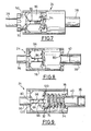
- la figure 3 est une vue en coupe axiale qui représente l'embout mâle de la figure 1 ;
- la figure 4 est une vue de profil en coupe axiale qui représente une première étape d'accouplement dans laquelle l'embout mâle est dans une position d'emmanchement dans l'embout femelle ;
- la figure 5 est une vue en perspective à plus grande échelle qui représente un détail de l'embout femelle ;
- la figure 6 est une vue de profil avec arrachement qui représente une deuxième étape d'accouplement de l'embout mâle avec l'embout femelle ;
- la figure 7 est une vue similaire à celle de la figure 6 qui représente une troisième étape d'accouplement ;
- la figure 8 est une vue similaire à celle de la figure 6 qui représente une quatrième étape d'accouplement ;
- la figure 9 est une vue similaire à celle de la figure 4 qui représente une cinquième étape d'accouplement ;
- la figure 10 est une vue similaire à celle de la figure 6 qui représente une sixième étape d'accouplement ;
- la figure 11 est une vue similaire à celle de la figure 6 qui représente une septième étape d'accouplement ;
- la figure 12 est une vue similaire à celle de la figure 4 qui représente l'embout mâle en position accouplée avec l'embout femelle ;
- la figure 13 est une vue similaire à celle de la figure 4 qui représente une première étape de désaccouplement ;
- la figure 14 est une vue similaire à celle de la figure 4 qui représente une deuxième étape de désaccouplement.
- Figure 1 is an exploded perspective view showing a male end and a female end of a coupling device according to the invention;
- Figure 2 is a cutaway perspective view showing the end caps of Figure 1 in an intermediate position between a disassembled position and a coupled position;
- Figure 3 is an axial sectional view which shows the male end of Figure 1;
- Figure 4 is a side view in axial section which shows a first coupling step in which the male end is in a fitting position in the socket;
- Figure 5 is a perspective view on a larger scale which shows a detail of the socket;
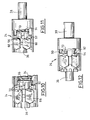
- Figure 6 is a cutaway side view which shows a second coupling step of the male end with the socket;
- Figure 7 is a view similar to that of Figure 6 which shows a third coupling step;
- Figure 8 is a view similar to that of Figure 6 which shows a fourth coupling step;
- Figure 9 is a view similar to that of Figure 4 which shows a fifth coupling step;
- Figure 10 is a view similar to that of Figure 6 which shows a sixth coupling step;
- Fig. 11 is a view similar to that of Fig. 6 showing a seventh coupling step;
- Figure 12 is a view similar to that of Figure 4 which shows the male end in position coupled with the socket;
- Figure 13 is a view similar to that of Figure 4 which shows a first uncoupling step;
- Figure 14 is a view similar to that of Figure 4 which shows a second decoupling step.
Dans la suite de la description, on adoptera à titre non limitatif une orientation axiale dirigée d'arrière en avant et indiquée par la flèche "A" de la figure 1. On définit aussi à titre non limitatif un sens de rotation positif autour de l'axe "A" qui est indiqué par la flèche "R" de la figure 5 et qui correspond au sens horaire en regardant dans la direction axiale "A" vers l'avant.In the remainder of the description, it will be adopted without limitation an axial orientation directed from back to front and indicated by the arrow "A" of Figure 1. It also defines a non-limiting direction of positive rotation around the l "A" axis which is indicated by the arrow "R" of Figure 5 and which corresponds to the clockwise direction while looking in the axial direction "A" towards the front.
Dans la suite de la description, des éléments similaires, analogues ou identiques seront désignés par des mêmes numéros de référence.In the rest of the description, similar, analogous or identical elements will be designated by the same reference numbers.
On a représenté à la figure 1 une extrémité libre 20 d'une première conduite qui est située à gauche de la figure 1, et une extrémité libre 22 d'une deuxième conduite qui est située à droite de la figure 1.FIG. 1 shows a
L'une des conduites est ici raccordée à un réservoir (non représenté) de liquide de nettoyage embarqué à bord d'un véhicule automobile tandis que l'autre conduite est raccordée à un gicleur de nettoyage d'une glace de projecteur du véhicule automobile (non représentée).One of the lines is here connected to a reservoir (not shown) of cleaning fluid on board a motor vehicle while the other pipe is connected to a nozzle for cleaning a searchlight of the motor vehicle (not shown).
Les embouchures des deux extrémités libres 20, 22 sont destinées à être accouplées l'une à l'autre par l'intermédiaire d'un dispositif d'accouplement 24 pour permettre l'alimentation du gicleur en liquide de nettoyage.The mouths of the two
A cet effet, les embouchures des deux extrémités libres sont agencées en vis-à-vis l'une de l'autre de manière qu'elles soient accouplées l'une à l'autre le long de l'axe "B" comme représenté à la figure 2.For this purpose, the mouths of the two free ends are arranged vis-à-vis one another so that they are coupled to each other along the axis "B" as shown in Figure 2.
Le dispositif 24 pour le raccordement des deux extrémités 20, 22 comporte un premier embout mâle 26, qui est représenté à gauche aux figures, et un deuxième embout femelle 28 qui est représenté à droite aux figures.The
Comme représenté à la figure 1, l'embout mâle 26 comporte un corps 30 de forme globalement tubulaire coaxial à l'axe "B" qui est ouvert à ses deux extrémités. L'embout mâle 26 comporte aussi une bague 32 coaxiale à l'axe "B" et un ressort hélicoïdal cylindrique 34 coaxial à l'axe "B".As shown in Figure 1, the
L'embout femelle 28 comporte ici une pièce unique de forme tubulaire coaxiale à l'axe "B".The
Chaque embout 26, 28 est apte à être adapté à l'extrémité libre 20, 22 de la conduite associée.Each
Ainsi, le corps 30 de l'embout mâle 26 comporte un tronçon d'extrémité arrière 36 cylindrique de raccord qui est destiné à être inséré à force dans l'embouchure de l'extrémité libre 20 de la première conduite.Thus, the
De manière similaire, l'embout femelle 28 comporte un tronçon d'extrémité avant 38 cylindrique de raccord qui est destiné à être inséré à force dans l'embouchure de l'extrémité libre 22 de la deuxième conduite.Similarly, the
Avantageusement, le tronçon d'extrémité de raccord 36, 38 de chaque embout 26, 28 est fixé de manière étanche à la conduite associée à l'aide d'un collier (non représenté) qui serre l'extrémité libre 20, 22 autour du tronçon d'extrémité de raccord 36, 38.Advantageously, the connecting
On décrit à présent l'embout mâle 26 en référence aux figures 1 et 3.We now describe the
Le corps tubulaire 30 de l'embout mâle 26 comporte un tronçon d'extrémité avant cylindrique qui forme une portée 40 qui est destinée à être emmanchée axialement d'arrière vers l'avant de manière étanche dans le tronçon avant de raccord 38 de l'embout femelle 28 dans une position accouplée de l'embout mâle 26 avec l'embout femelle 28 dans laquelle les deux conduites 20, 22 sont raccordées de manière étanche.The
Le corps 30 comporte aussi un tronçon central 42 qui est destinée à recevoir à rotation la bague 32. Le diamètre du tronçon central 42 est ici sensiblement le même que celui du tronçon d'extrémité arrière de raccord 36 de l'embout mâle 26.The
Un tronçon intermédiaire 44 est interposé entre le tronçon central 42 et la portée avant 40. Le tronçon intermédiaire 44 a un diamètre inférieur aux diamètres du tronçon central 42 et de la portée avant 40. Ainsi, ce tronçon intermédiaire 44 est délimité axialement par deux épaulements radiaux arrière 46 et avant 48.An
Le corps 30 comporte enfin un collet 50 qui est interposé entre le tronçon d'extrémité arrière de raccord 36 et le tronçon central 42.The
La face radiale arrière 52 du collet 50 est destinée à former une butée pour le bord annulaire de l'embouchure de l'extrémité libre 20 lors de l'insertion du tronçon d'extrémité arrière de raccord 36 à l'intérieur de l'extrémité libre 20.The rear
La face radiale annulaire avant 54 du collet 50 présente une surface en couronne dentelée formée d'une succession de pentes "montantes" 55 et de pentes "descendantes" 56 qui sont orientées tangentiellement au corps 30. Par pente "montante", on entend une pente qui est inclinée d'arrière en avant selon le sens de rotation positif "R", et par pente "descendante", on entend une pente qui est inclinée d'avant en arrière toujours selon le sens positif de rotation "R".The annular
Comme on le verra par la suite, les pentes "descendantes" 56 du collet 50 sont destinées à former des rampes de guidage en rotation de la bague 32 pour le verrouillage de l'accouplement de l'embout mâle 26 avec l'embout femelle 28.As will be seen later, the "downward" slopes 56 of the
La face cylindrique périphérique 58 du collet 50 comporte des doigts 60 qui s'étendent radialement vers l'extérieur. Les doigts 60 sont ici au nombre de dix et ils sont répartis régulièrement autour de la face périphérique 58.The cylindrical
Ces doigts 60 sont destinés à coopérer avec des plans complémentaires d'indexation de l'embout femelle 28 qui seront décrits par la suite, afin d'indexer la position angulaire du corps 30 autour de l'axe "B" par rapport à l'embout femelle 28. A cet effet, la face radiale avant 62 des doigts 60 est profilée en forme de "V" dont la pointe est orientée vers l'avant.These
Comme représentée à la figure 3, la bague 32 est montée folle en rotation sur le tronçon central 42 du corps 30 autour de l'axe "B", et elle est aussi montée coulissante par rapport au corps 30 selon la direction axiale "A".As shown in Figure 3, the
Le bord d'extrémité avant de la bague 32 comporte une collerette 64 qui s'étend radialement vers l'intérieur, c'est-à-dire en direction de l'axe "B". La collerette 64 est reçu autour du tronçon intermédiaire 44 et axialement entre les épaulements 46, 48.The front end edge of the
Par ailleurs, la face radiale annulaire arrière 66 de la bague 32 présente une surface en couronne dentelée complémentaire de celle de la face avant 54 du collet 50 du corps 30 de sorte que la face arrière dentelée 66 de la bague 32 puisse être imbriquée axialement dans la face avant dentelée 54 du collet 50.Furthermore, the rear annular
Ainsi, la face arrière 66 de la bague 32 comporte une succession de pentes "montantes" 67 et de pentes "descendantes" 68, comme illustré à la figure 2.Thus, the
Le coulissement axial de la bague 32 par rapport au corps 30 est limité vers l'avant par le contact de la collerette 64 avec l'épaulement avant 48, et, comme illustré à la figure 3, vers l'arrière par le contact entre la face arrière 66 de la bague 32 et la face avant 54 du collet 50.The axial sliding of the
La bague 32 comporte aussi des ergots 70 qui s'étendent radialement vers l'extérieur depuis le pourtour de la bague 32. Les ergots 70 sont ici au nombre de cinq et ils sont répartis régulièrement sur le pourtour de la bague 32.The
La face radiale avant des ergots 70 est conformée en "V" dont la pointe est orientée vers l'avant.The radial front face of the
De plus, la distance radiale entre l'axe "B" et l'extrémité libre des ergots 70 est supérieure à la distance radiale entre l'axe "B" et l'extrémité libre des doigts d'indexation 60 du collet 50.In addition, the radial distance between the axis "B" and the free end of the
Ces ergots 70 forment des premiers moyens de blocage axial qui ont une fonction de verrouillage de l'embout mâle 26 dans sa position accouplée avec l'embout femelle 28.These
Un tronçon d'extrémité avant 72 de la bague 32 est destiné à être introduit coaxialement dans un tronçon d'extrémité arrière du ressort cylindrique 34. La bague 32 comporte aussi un épaulement radial central d'appui 74 orienté vers l'avant sur lequel l'extrémité arrière du ressort 34 est destiné à être en appui comme représenté à la figure 3.A
Le ressort 34 s'étend ainsi radialement autour du corps 30 de l'embout mâle 26.The
Avantageusement, le ressort 34 est fixé à la bague 32 de manière à ce qu'il ne soit pas accidentellement séparé de l'embout mâle 26.Advantageously, the
En se reportant aux figures 4 et 5, on décrit maintenant l'embout femelle 28.Referring to FIGS. 4 and 5, the
L'embout femelle 28 comporte un tronçon d'extrémité arrière 76 cylindrique tubulaire qui prolonge coaxialement vers l'arrière son tronçon d'extrémité avant de raccord 38. Le diamètre du tronçon d'extrémité arrière 76 est sensiblement plus grand que le diamètre du tronçon d'extrémité avant 38.The
Le fond radial d'extrémité avant 78 du tronçon arrière 76 comporte un orifice coaxial 80 qui débouche dans l'extrémité avant de raccord 38.The front end
Le diamètre intérieur du tronçon d'extrémité arrière 76 est suffisamment grand pour loger l'embout mâle 26.The inside diameter of the
Le diamètre intérieur de l'extrémité avant de raccord 38 est adapté pour recevoir la portée avant 40 de l'embout mâle 26 de manière à raccorder de manière étanche les deux extrémités libres 20, 22 des conduites.The inside diameter of the
Avantageusement, la portée avant 40 de l'embout mâle comporte un joint torique (non représenté) qui est destiné à être intercalé entre la face cylindrique extérieure de la portée avant 40 et la face cylindrique intérieure du tronçon avant de raccord 38 de l'embout femelle 26 pour assurer l'étanchéité du raccord.Advantageously, the forward bearing
Pour faciliter l'emmanchement axial de la portée avant 40 de l'embout mâle 26 dans le tronçon avant de raccord 38 de l'embout femelle 28, le contour du bord d'extrémité de la portée avant 40 comporte un chanfrein 82 et le fond 78 du tronçon arrière 76 de l'embout femelle 28 comporte une zone périphérique 84 de l'orifice coaxial 80 en forme d'entonnoir pour guider la portée avant 40 jusqu'à l'orifice coaxial 80.To facilitate the axial fitting of the
Le tronçon arrière 76 de l'embout femelle 28 comporte aussi un manchon 86 qui s'étend radialement vers l'intérieur depuis la face cylindrique intérieure 88 du tronçon arrière 76. Le manchon 86 est ici formé venu de matière avec le tronçon arrière 76.The
Le manchon 86 est représenté plus en détail à la figure 5.The
La face cylindrique intérieure 95 du manchon 86 a un diamètre intérieur suffisant pour permettre le passage du collet 50, mais ce diamètre intérieur n'est pas suffisant pour permettre le passage des doigts d'indexation 60 du collet 50.The inner
La face radiale annulaire avant du manchon 86 comporte des crans 90 qui sont ici au nombre de cinq.The front annular radial face of the
En tournant autour de l'axe "B" dans le sens positif "R", qui correspond à un sens antihoraire en se reportant à la figure 5, chaque cran 90 est délimité en amont par une rampe de verrouillage 92 "descendante" d'avant vers l'arrière et en aval par une face de blocage 94 orientée axialement perpendiculairement à une direction tangente. Le fond du cran 90 est ainsi formé par l'intersection de l'extrémité arrière de la pente de verrouillage 92 et de la face de blocage 94.Turning about the axis "B" in the positive direction "R", which corresponds to a counterclockwise direction with reference to FIG. 5, each
Chaque cran 90 forme des deuxièmes moyens de blocage axial qui est destiné à recevoir un ergot 70 de la bague 32 de l'embout mâle 26 lorsque l'ergot 70 est dans une position angulaire de verrouillage, de manière à verrouiller axialement l'embout mâle 26 dans sa position accouplée par rapport à l'embout femelle 28.Each
La face cylindrique interne 95 du manchon comporte des rainures axiales 96 qui sont interposées entre les crans 90. Le manchon 86 comporte ici cinq rainures axiales 96. Les extrémités avant et arrière de chaque rainure 96 sont débouchantes dans les faces radiales annulaires avant et arrière du manchon 86.The inner
Les rainures axiales 96 sont réparties autour du manchon 86 en alternance avec les crans 90, c'est-à-dire que les rainures 96 ne sont pas alignées axialement avec les crans 90.The
Chaque rainure axiale 96 est agencée de manière que qu'une première extrémité avant de la rampe de verrouillage 92 associée soit adjacente à l'extrémité avant de la rainure d'insertion 96.Each
Les rainures axiales 96 sont suffisamment profondes pour recevoir les ergots 70 en coulissement axial le long du manchon 86 jusqu'aux crans 90 pour permettre un verrouillage du type à baïonnette de l'embout mâle 26 en position accouplée avec l'embout femelle 28.The
Les rainures axiales 96 forment ainsi des rainures d'insertion qui sont destinées à permettre l'insertion des ergots 70 jusqu'aux crans 90. Mais ces rainures axiales 96 sont aussi des rainures de libération qui permettent de retirer les ergots 70 lors du désaccouplement de l'embout mâle 26.The
La face radiale annulaire avant du manchon 86 comporte aussi des rampes de libération 97 dont chacune est associée à un cran 90. Plus particulièrement, en tournant selon le sens positif "R" autour de la face radiale avant du manchon 86, chaque rampe de libération 97 est agencée en aval du cran 90 associé et elle présente un plan incliné d'avant en arrière similaire à celui des rampes de verrouillage 92. L'extrémité amont arrière de la rampe de libération 97 est adjacente à la face de blocage 94, tandis que son extrémité aval arrière débouche à l'extrémité avant d'une rainure d'insertion 96.The front annular radial face of the
Par ailleurs, la face radiale annulaire arrière du manchon 86 est crénelée de manière à comporter une succession de plans inclinés 98 "montants" et "descendants". L'extrémité arrière débouchante de chaque rainure 96 est ainsi flanquée de deux plans inclinés 98 qui convergent en entonnoir vers la rainure 96.Furthermore, the rear annular radial face of the
Ainsi, entre deux rainures 96 successives, la face radiale arrière du manchon 86 comporte deux plans inclinés 98 qui forment un "V" dont la pointe est dirigée vers l'arrière, chaque pointe étant ici globalement alignée axialement avec un cran 90.Thus, between two
Ces plans inclinés 98 sont destinés à coopérer avec les doigts d'indexation 60 et avec les ergots 70 pour indexer la position angulaire du corps 30 et de la bague 32 par rapport à l'embout femelle 28. Par la suite, ils seront donc qualifiés de plans d'indexation 98.These
La face cylindrique intérieure 95 du manchon 86 comporte enfin des cannelures axiales 100. Les cannelures 100 sont au nombre de cinq et elles sont agencées à intervalle régulier dans la face cylindrique intérieure 95 en alternance avec les rainures 96. Les deux extrémités avant et arrière de chaque cannelure 100 sont débouchantes dans les faces radiales avant et arrière du manchon 86. Plus particulièrement, l'extrémité arrière de chaque cannelure 100 débouche au niveau de la pointe formée par deux plans d'indexation 98 adjacents.The inner
Les cannelures 100 sont suffisamment profondes pour recevoir les doigts d'indexation 60 de l'embout mâle 26 en coulissement axial, mais elles ne sont pas suffisamment profondes pour recevoir les ergots 70 en coulissement axialThe
Ainsi, les cinq cannelures 100 en association avec les cinq rainures 96 sont aptes à recevoir simultanément en coulissement axial les dix doigts d'indexation 60 de l'embout mâle 26.Thus, the five
On se reporte à présent aux figures 6 à 12 pour décrire le fonctionnement du dispositif 24 lors de l'opération d'accouplement des extrémités libres 20, 22 des deux conduites.Referring now to Figures 6 to 12 to describe the operation of the
Dans la suite de la description et à titre non limitatif, l'embout femelle 28 sera choisi comme une référence fixe pour les mouvements en translation axial et en rotation de l'embout mâle 26.In the remainder of the description and in a nonlimiting manner, the
On a représenté à la figure 6 l'embout mâle 26 dans une position arrière démontée par rapport à l'embout femelle 28 dans laquelle la portée avant 40 de l'embout mâle 26 a été insérée axialement dans le manchon 86 du tronçon arrière 76 de l'embout femelle 28, selon un mouvement axial d'accouplement qui est dirigé d'arrière en avant. Cependant, la portée 40 n'est pas encore emmanchée dans le tronçon de raccord avant 38 de l'élément femelle 28.FIG. 6 shows the
La face dentelée arrière 66 de la bague 32 est en butée contre la face dentelée avant 54 du collet 50 du corps 30.The rear
Comme illustré à la figure 6, les ergots 70 de la bague 32 ne sont pas ici alignés axialement avec les rainures d'insertion 96. Lors du mouvement d'accouplement, les faces radiales avant des ergots 70 entrent alors en contact avec les plans d'indexation 98 du manchon 86.As illustrated in FIG. 6, the
Comme représenté à la figure 7, en poursuivant le mouvement axial d'accouplement vers l'avant de l'embout mâle 26, les ergots 70 glissent contre les plans d'indexation 98 du manchon 86 de manière à provoquer automatiquement la rotation de la bague 32 vers une position angulaire d'engagement dans laquelle les ergots 70 sont alignés axialement avec les rainures d'insertion 96. Le corps 30 de l'embout mâle 26 est alors dans une position axiale dite d'emmanchement.As shown in FIG. 7, while continuing the axial movement of coupling towards the front of the
On remarquera que pour que le dispositif 24 selon l'invention fonctionne correctement, il est donc important que l'imbrication de la face dentelée avant 54 du collet 50 dans la face dentelée arrière 66 de la bague 32 n'empêche pas la bague 32 de tourner en coulissant par rapport au corps 30 lorsque le ressort 34 ne pousse pas axialement la bague 32 contre le collet 50 comme c'est le cas lorsque le corps 30 est en position d'emmanchement.It will be noted that for the
Comme on le verra par la suite, seules les pentes "descendantes" 56, 68 sont utilisées pour réaliser le verrouillage du dispositif 24, cependant elles sont aussi apte à permettre la rotation de la bague 32 dans le sens inverse du sens positif "R" par rapport au corps 30 lorsque les faces dentelées avant 54 et arrière 66 sont en contact l'une avec l'autre en provoquant un léger mouvement de coulissement axial de la bague 32 vers l'avant par rapport au corps 30'.As will be seen later, only the "downward" slopes 56, 68 are used to lock the
De même, les pentes "montantes" 55, 67 permettent à la bague 32 de tourner dans le sens positif par rapport au corps 30.Similarly, the "rising" slopes 55, 67 allow the
La forme en "V" de la face radial avant des ergots 70 permet avantageusement de faire tourner la bague 32 dans un sens ou dans l'autre lorsque les ergots 70 sont malencontreusement agencés en vis-à-vis des pointes formées par deux plans d'indexation 98 adjacents. Il n'existe ainsi pas de position angulaire de la bague 32 dans laquelle le mouvement axial d'accouplement est bloqué.The "V" shape of the radial front face of the
Comme représenté à la figure 8, en poursuivant le mouvement axial d'accouplement vers l'avant de l'embout mâle 26, les ergots 70 sont engagés en coulissement axial dans les rainures d'insertion 96 en bloquant ainsi la rotation de la bague 32 par rapport à l'embout femelle 28. Le collet 50 du corps 30 de l'embout mâle 26 commence alors à pénétrer dans le manchon 86.As represented in FIG. 8, by continuing the axial movement of coupling towards the front of the
Les doigts d'indexation 60 du collet 50 sont ici alignés axialement avec les rainures d'insertion 96 et avec les cannelures 100 du manchon.The
Cependant, lorsque les doigts d'indexation 60 du collet 50 ne sont pas alignés axialement avec les rainures d'insertion 96 et avec les cannelures 100, les doigts d'indexations 60 entrent à leur tour en contact avec les plans d'indexation 98 du manchon 86. Les plans d'indexation 98 guident alors cinq des dix doigts d'indexation 60 vers les rainures d'insertion 96, les cinq autres doigts d'indexation 60 étant par conséquent guidés vers les cannelures 100.However, when the
Les doigts d'indexation 60 en coopération avec les plans d'indexation 98 permettent ainsi d'indexer la position angulaire du corps 30 de l'embout mâle 26 par rapport au manchon 86 de l'embout femelle 28.The
Les faces radiales avant en forme de "V" des doigts d'indexation 60 ont la même fonction que les faces radiales avant en forme de "V" des ergots 70, c'est-à-dire éviter l'existence de positions angulaires de blocage en coulissement de l'embout mâle 26 par rapport à l'embout femelle 28.The "V" -shaped front radial faces of the
Par ailleurs, le fait de disposer de dix doigts d'indexation 60 permet avantageusement d'indexer la position angulaire du corps 30 de l'embout mâle 26 en pivotant le corps 30 autour de l'axe "B" d'un angle très faible par rapport à l'embout femelle 28. Ainsi, dans le cas présent, le corps 30 doit pivoter d'un angle de moins de 36° lorsque les doigts d'indexation 60 ne sont pas alignés.Moreover, the fact of having ten indexing
Comme illustré à la figure 8, à ce moment de l'accouplement, la portée avant 40 du corps 30 de l'embout mâle 26 est emmanchée dans le tronçon d'extrémité avant 38 de l'embout femelle 28 à travers l'orifice coaxial 80 du fond 78 du tronçon arrière 76 de l'embout femelle 28.As illustrated in FIG. 8, at this moment of coupling, the
Puis, comme représenté à la figure 9, les ergots 70 étant toujours engagés dans la rainure d'insertion 96, les doigts d'indexation 60 sont à leur tour reçus en coulissement axial dans les rainures d'insertion 96 et dans les cannelures 100.Then, as shown in FIG. 9, the
L'extrémité avant du ressort 34 entre alors en contact avec le fond 78 du tronçon arrière 76 de l'embout femelle 28. Le ressort 34 est ainsi comprimé entre la bague 32 et le fond 78 à mesure que l'embout mâle 26 est déplacé selon le mouvement axial d'accouplement. Le ressort 34 exerce ainsi une force axiale de rappel dirigée d'avant en arrière sur la bague 32 qui est poussée contre la face avant dentelée 54 du collet 50.The front end of the
Comme représenté à la figure 9, la face arrière dentelée 66 de la bague 32 n'est pas totalement imbriquée dans la face avant dentelée 54 du collet 50. Plus particulièrement, seules les pentes "descendantes" 68 de la bague 32 sont en contact avec les pentes "descendantes" 56 du collet 50.As shown in FIG. 9, the serrated
La force de rappel du ressort 34 incite les pentes "descendantes" 68 de la bague à glisser le long des pentes "descendantes" 56 du collet 50 de manière que la bague 32 tourne dans le sens positif "R" par rapport au corps 30 pour que les faces dentelées complémentaires 54, 66 soient imbriquées l'une dans l'autre.The restoring force of the
Cependant, les ergots 70 qui sont engagés dans les rainures d'insertion 96, empêchent la bague 32 de tourner par rapport à l'embout femelle 28, et les doigts d'indexation 60 du collet 50 qui sont engagés dans les cannelures 100, empêchent le corps 30 de tourner par rapport à l'embout femelle 28. Le mouvement de rotation relatif entre la bague 32 et le corps 30 est donc bloqué.However, the
Le mouvement axial d'accouplement est poursuivi jusqu'à ce que le corps 30 atteigne une position axiale avant transitoire qui est illustrée à la figure 10 et dans laquelle les pentes 56 de la face avant dentelée 54 du collet 50 sont agencées dans le prolongement vers l'avant des rampes de verrouillage 92 du manchon 86.The axial coupling movement is continued until the
Dans sa position avant transitoire, le corps 30 est axialement en avant par rapport à sa position avant accouplée.In its position before transient, the
Dans cette position avant transitoire, les ergots 70 de la bague 32 sont sortis de la rainure d'insertion 96. La bague 32 est donc de nouveau libre de tourner par rapport au corps 30 et par rapport à l'embout femelle 28, tandis que le corps 30 est toujours solidaire en rotation de l'embout femelle 28.In this position before transient, the
Le ressort 34 qui a été comprimé lors du mouvement d'accouplement pousse alors la bague 32 vers l'arrière. Les pentes "descendantes" 66 de la bague 32 glissent alors contre les pentes "descendantes" 56 du collet 50 de manière que la bague 32 soit animée automatiquement et simultanément d'un mouvement de coulissement axial vers l'arrière par rapport au corps 30, et d'un mouvement rotatif dans le sens positif "R" vers une position angulaire intermédiaire de verrouillage dans laquelle la face arrière dentelée 66 de la bague 32 est complètement imbriquée dans la face avant dentelée 54 du collet 50.The
Les ergots 70 sont alors engagés sur les rampes de verrouillage 92 du manchon 86 comme illustré à la figure 11.The
Le mouvement axial d'accouplement cesse alors d'être appliqué au corps 30. La bague 32 folle en rotation est alors poussée par le ressort 34 contre les rampes de verrouillage 92, et la bague 32 n'est plus en butée contre le collet 50, mais contre le manchon 86.The axial coupling movement then ceases to be applied to the
Les ergots 70 glissent alors automatiquement sur les rampes de verrouillage 92 jusqu'au fond des crans 90 en provoquant le pivotement dans le sens positif "R" de la bague 32 jusqu'à sa position angulaire de verrouillage.The
Simultanément, le corps 30 de l'embout mâle 26 est repoussé axialement vers l'arrière par le ressort 34 par l'intermédiaire de la bague 32.Simultaneously, the
Les ergots 70 sont avantageusement maintenus au fond des crans 90 associés par la force axiale du ressort 34. Ainsi, l'embout mâle 26 est verrouillé à l'embout femelle 28 en position accouplée quelle que soit l'orientation de l'axe "B" par rapport à la gravité.The
La bague 32 est alors fixe par rapport à l'embout femelle 28, tandis que le corps 30 est libre de coulisser par rapport à la bague 32 dans les limites permises par la face avant 54 du collet 50 et par l'épaulement avant 48 du corps 30, ou de tourner par rapport à la bague 32.The
On décrit à présent le fonctionnement du dispositif 24 lors du désaccouplement des embouts mâle 26 et femelle 28 en se référant aux figures 13 et 14.We now describe the operation of the
Pour déverrouiller l'embout mâle 26, il faut appliquer au corps 30 un mouvement axial de désaccouplement vers l'avant similaire au mouvement axial d'accouplement.To unlock the
Les doigts d'indexation 60 du collet 50 sont alors de nouveau engagés dans les rainures d'insertion 96 et dans les cannelures 100 comme décrit pour l'accouplement.The
Puis, les pentes "descendantes" 56 de la face avant dentelée 54 du collet 50 entrent en contact avec les pentes "descendantes" 68 de la face arrière dentelée 66 de la bague 32.Then, the "downward" slopes 56 of the serrated
En poursuivant le mouvement axial de désaccouplement vers l'avant, la face avant dentelée 54 du collet 50 pousse la face arrière dentelée 66 de la bague 32. La face avant dentelée 54 du collet 50 n'est pas totalement imbriquée dans la face arrière dentelée 66 de la bague 32. Plus particulièrement, seules les pentes "descendantes" 68 de la bague 32 sont en contact avec les pentes "descendantes" 56 du collet 50.By continuing the forward axial disengagement movement, the serrated
La force de rappel du ressort 34 incite les pentes "descendantes" 68 de la bague à glisser le long des pentes "descendantes" 56 du collet 50 de manière que la bague 32 tourne dans le sens positif "R" par rapport au corps 30 pour que les faces dentelées complémentaires 54, 66 soient imbriquées l'une dans l'autre.The restoring force of the
Cependant, les ergots 70 sont au contact de la face de blocage 94 associée du cran 90, bloquant ainsi la rotation de la bague 32 dans le sens positif "R" par rapport au corps 30 qui est lui-même solidaire en rotation de l'embout femelle 28 par l'intermédiaire des doigts d'indexation 60.However, the
La bague 32 coulisse donc vers l'avant, poussée par le corps 30, jusqu'à ce que le corps 30 soit dans sa position extrême avant transitoire comme représentée à la figure 13. Dans cette position avant transitoire, les pentes "descendantes" 56 du collet 50 sont agencées dans le prolongement vers l'avant des rampes de libération 97 du manchon 86.The
Les ergots 70 ne sont alors plus bloqués en rotation par les faces de blocage 94. La force de rappel du ressort 34 pousse donc la bague 32 contre le collet 50, et elle provoque ainsi la rotation automatique de la bague 32 dans le sens positif vers une position angulaire intermédiaire de déverrouillage dans laquelle la face arrière dentelée 66 de la bague 32 est complètement imbriquée dans la face avant dentelée 54 du collet 50, et dans laquelle les ergots 70 sont engagés sur les rampes de libération 97.The
Le mouvement axial de désaccouplement cesse alors d'être appliqué au corps 30. La bague 32 folle en rotation est alors poussée par le ressort 34 contre les rampes de verrouillage 92, et la bague 32 n'est plus en butée contre le collet 50, mais contre le manchon 86.The axial uncoupling movement then ceases to be applied to the
Le ressort 34 continue d'exercer sa force de rappel qui pousse les ergots 70 vers l'arrière contre les rampes de libération 97. Les ergots 70 glissent le long des rampes de libération 97 vers l'arrière, provoquant ainsi la rotation de la bague 32 dans le sens positif "R" jusqu'à une position angulaire de libération qui est ici identique à la position angulaire d'engagement de la bague 32 dans laquelle les ergots sont alignés avec les rainures d'insertion 96 du manchon 86.The
La rotation de la bague 32 entraîne le coulissement du corps 30 vers l'arrière par rapport à la bague 32.The rotation of the
Puis, comme représenté à la figure 14, le ressort pousse les ergots 70 vers l'arrière de manière qu'ils soient engagés dans les rainures d'insertion 96.Then, as shown in FIG. 14, the spring pushes the
L'embout mâle 26 n'est alors plus verrouillé par rapport à l'embout femelle 28, et il est possible de désaccoupler le dispositif 24 en tirant simplement l'embout mâle 26 vers l'arrière.The
Le ressort 34 donne avantageusement une impulsion suffisante pour projeter l'embout mâle 26 hors de l'embout femelle 28.The
Ainsi, grâce au dispositif selon 24 l'invention, l'opérateur ne doit appliquer qu'un mouvement axial d'accouplement à l'embout mâle 26 pour que ce dernier soit raccordé et aussi verrouillé.Thus, thanks to the device according to the invention, the operator must apply only an axial coupling movement to the
Le dispositif 24 permet aussi de déverrouiller l'embout mâle 26 en lui appliquant un mouvement axial de désaccouplement.The
Selon une variante non représentée de l'invention, le ressort 34 fait partie de l'embout femelle 28. Il est agencé dans le tronçon d'extrémité arrière 76 de manière coaxiale. Son extrémité avant est par exemple fixée au fond 78 du tronçon arrière 78 en entourant l'orifice 80. Ainsi, lorsque l'embout mâle 26 est inséré dans l'embout femelle 28, la portée avant 40 de l'embout mâle 26 traverse coaxialement le ressort 34, et l'épaulement radial d'appui 74 de la bague 32 entre en contact avec l'extrémité arrière du ressort 34 qui est alors comprimé entre le fond 78 de l'embout femelle 28 et la bague 32 comme décrit précédemment.According to a not shown variant of the invention, the
On a décrit l'invention pour le raccordement de deux conduites de nettoyage, on comprendra que l'invention s'applique aussi à des conduites destinées à conduire tout autre type de fluide, voire à des câbles conducteurs d'électricité, de signaux optiques, etc.The invention has been described for the connection of two cleaning lines, it will be understood that the invention also applies to pipes intended to drive any other type of fluid, or even cables conducting electricity, optical signals, etc.
Claims (11)
et du type qui comporte des moyens (70, 90) pour le verrouillage à baïonnette de l'embout mâle (26) en position accouplée avec l'embout femelle (28) qui comportent des premiers moyens (70) de blocage axial qui sont portés par l'embout mâle (26) qui sont destinés à coopérer avec des deuxièmes moyens (90) de blocage axial qui sont portés par l'embout femelle (28), le verrouillage a baïonnette étant obtenu par rotation des premiers moyens (70) dans un sens positif par rapport aux deuxièmes moyens (90) entre une position angulaire d'engagement et une position angulaire de verrouillage,
caractérisé en ce qu'il comporte des moyens de guidage en rotation (56, 68, 92) munis de moyens élastiques de rappel (34), qui provoquent la rotation automatique des premiers moyens de verrouillage (70) dans le sens positif (R) pour provoquer le verrouillage à baïonnette lorsque l'embout mâle (26) est emmanché axialement dans l'embout femelle (28) depuis sa position arrière démontée jusqu'à sa position avant accouplée.Device (24) for the removable coupling of the free ends (20, 22) of two pipes, in particular of fluid, which comprises two coaxial ends among which:
and of the type which comprises means (70, 90) for the bayonet locking of the spigot (26) in position coupled with the spigot (28) which comprise first axial locking means (70) which are carried by the spigot end (26) which are intended to cooperate with second axial locking means (90) which are carried by the spigot (28), the bayonet lock being obtained by rotation of the first means (70) in a positive direction relative to the second means (90) between an angular position of engagement and a locking angular position,
characterized in that it comprises rotational guiding means (56, 68, 92) provided with resilient biasing means (34), which causes the automatic rotation of the first locking means (70) in the positive direction (R). to cause the bayonet lock when the spigot (26) is axially engaged in the socket (28) from its disassembled rear position to its mated front position.
Applications Claiming Priority (1)
| Application Number | Priority Date | Filing Date | Title |
|---|---|---|---|
| FR0503907A FR2884587B1 (en) | 2005-04-19 | 2005-04-19 | DEVICE FOR THE DISMANTLING COUPLING OF TWO PIPES WHICH INCLUDES AUTOMATIC LOCKING MEANS IN BAIONNETTE |
Publications (1)
| Publication Number | Publication Date |
|---|---|
| EP1715236A1 true EP1715236A1 (en) | 2006-10-25 |
Family
ID=35431918
Family Applications (1)
| Application Number | Title | Priority Date | Filing Date |
|---|---|---|---|
| EP06290440A Withdrawn EP1715236A1 (en) | 2005-04-19 | 2006-03-17 | Releasable coupling for two conduits, comprising automatic bayonet locking means |
Country Status (2)
| Country | Link |
|---|---|
| EP (1) | EP1715236A1 (en) |
| FR (1) | FR2884587B1 (en) |
Cited By (2)
| Publication number | Priority date | Publication date | Assignee | Title |
|---|---|---|---|---|
| CN107542967A (en) * | 2017-08-22 | 2018-01-05 | 九牧厨卫股份有限公司 | A kind of shower faucet of handwheel Quick assembling-disassembling structure and the application structure |
| CN109994884A (en) * | 2017-12-29 | 2019-07-09 | 泰科电子(上海)有限公司 | Connector assembly |
Families Citing this family (1)
| Publication number | Priority date | Publication date | Assignee | Title |
|---|---|---|---|---|
| CN117021156B (en) * | 2023-10-09 | 2024-01-16 | 之江实验室 | Device for robot limb assembly |
Citations (5)
| Publication number | Priority date | Publication date | Assignee | Title |
|---|---|---|---|---|
| US1673338A (en) * | 1926-01-23 | 1928-06-12 | Thomas E Mitchell | Pipe coupling |
| US3201151A (en) * | 1962-04-17 | 1965-08-17 | New York Air Brake Co | Pipe coupling having latching and locking means |
| FR2106694A5 (en) * | 1970-09-15 | 1972-05-05 | Staubli Sa Ets | |
| US20020163180A1 (en) | 1998-06-01 | 2002-11-07 | Micron Technology, Inc. | Ramp-lock fitting device |
| US20030085572A1 (en) * | 2001-11-06 | 2003-05-08 | Jean-Paul Froment | Quick connection for the removable join of two pipes |
-
2005
- 2005-04-19 FR FR0503907A patent/FR2884587B1/en not_active Expired - Fee Related
-
2006
- 2006-03-17 EP EP06290440A patent/EP1715236A1/en not_active Withdrawn
Patent Citations (5)
| Publication number | Priority date | Publication date | Assignee | Title |
|---|---|---|---|---|
| US1673338A (en) * | 1926-01-23 | 1928-06-12 | Thomas E Mitchell | Pipe coupling |
| US3201151A (en) * | 1962-04-17 | 1965-08-17 | New York Air Brake Co | Pipe coupling having latching and locking means |
| FR2106694A5 (en) * | 1970-09-15 | 1972-05-05 | Staubli Sa Ets | |
| US20020163180A1 (en) | 1998-06-01 | 2002-11-07 | Micron Technology, Inc. | Ramp-lock fitting device |
| US20030085572A1 (en) * | 2001-11-06 | 2003-05-08 | Jean-Paul Froment | Quick connection for the removable join of two pipes |
Cited By (2)
| Publication number | Priority date | Publication date | Assignee | Title |
|---|---|---|---|---|
| CN107542967A (en) * | 2017-08-22 | 2018-01-05 | 九牧厨卫股份有限公司 | A kind of shower faucet of handwheel Quick assembling-disassembling structure and the application structure |
| CN109994884A (en) * | 2017-12-29 | 2019-07-09 | 泰科电子(上海)有限公司 | Connector assembly |
Also Published As
| Publication number | Publication date |
|---|---|
| FR2884587B1 (en) | 2010-06-11 |
| FR2884587A1 (en) | 2006-10-20 |
Similar Documents
| Publication | Publication Date | Title |
|---|---|---|
| EP2439440B1 (en) | Coupling device with locking by threaded clamps and coupling including such a device | |
| EP1521027B1 (en) | Disconnection device for quick coupling | |
| EP2607770B1 (en) | Connector for performing the detachable connection of two fluid pipelines | |
| EP0665401B1 (en) | Quick acting coupling | |
| EP1752697B1 (en) | Connector assembly for fluidic circuit | |
| EP0722063B1 (en) | Quick acting safety coupling for the disconnectable connection of pipe lines | |
| EP1557599B1 (en) | Quick acting coupling and method of separating male and female parts of said coupling | |
| EP2278205B1 (en) | Female coupling element and quick acting coupling incorporating such an element | |
| EP1980782B1 (en) | Female connection element and a quick connector including such a female element | |
| EP2818781A1 (en) | Female quick-connection element and quick connection including such an element | |
| EP2236894A1 (en) | Coupling for transport of fluid and associated method of assembly / disassembly | |
| EP0224393A1 (en) | Disengageable clutch release bearing assembly with a disconnecting element on the release bearing, especially for an automotive vehicle | |
| EP1715236A1 (en) | Releasable coupling for two conduits, comprising automatic bayonet locking means | |
| FR2943585A1 (en) | GROUP OF TWO FUEL TUBE FILLING END SYSTEMS OF A VEHICLE. | |
| EP3670992B1 (en) | Female connection element and fluid connector including a male connection element and said female connection element | |
| EP1250548A1 (en) | Connecting device for conduits | |
| EP3640516A1 (en) | Quick coupling device | |
| EP0060735A1 (en) | Anchoring device for the end of a conduit with a slidable inner control cable | |
| EP3016563B1 (en) | Coupling device for suction duct | |
| FR2865014A1 (en) | Drive cable guiding duct maintaining end part for motor vehicle`s gear box, has sleeve that moves on cylindrical section using torsion spring between open position for positioning part in cavity of wall and closed position for locking part | |
| EP0695903B1 (en) | Tight and separable connection arrangement of a conduit with the end of a connection | |
| FR2810716A1 (en) | Connector for pipes forming part of car exhaust system comprises male and female connectors with conical sections which fit together at their widest part and biconical sleeve with narrower sections outwards which fits over them | |
| FR2910086A1 (en) | Sheath terminal for manual gearbox of motor vehicle, has sheath support body including detection unit detecting axial position with respect to support body for detecting locking of terminal on sheath stop plate | |
| FR2843790A1 (en) | Pipe connector has open ring shaped locking element of deformable elastic material movably connected to hollow holder for insertion at any time |
Legal Events
| Date | Code | Title | Description |
|---|---|---|---|
| PUAI | Public reference made under article 153(3) epc to a published international application that has entered the european phase |
Free format text: ORIGINAL CODE: 0009012 |
|
| AK | Designated contracting states |
Kind code of ref document: A1 Designated state(s): AT BE BG CH CY CZ DE DK EE ES FI FR GB GR HU IE IS IT LI LT LU LV MC NL PL PT RO SE SI SK TR |
|
| AX | Request for extension of the european patent |
Extension state: AL BA HR MK YU |
|
| 17P | Request for examination filed |
Effective date: 20070322 |
|
| 17Q | First examination report despatched |
Effective date: 20070504 |
|
| AKX | Designation fees paid |
Designated state(s): AT BE BG CH CY CZ DE DK EE ES FI FR GB GR HU IE IS IT LI LT LU LV MC NL PL PT RO SE SI SK TR |
|
| STAA | Information on the status of an ep patent application or granted ep patent |
Free format text: STATUS: THE APPLICATION IS DEEMED TO BE WITHDRAWN |
|
| 18D | Application deemed to be withdrawn |
Effective date: 20071115 |