EP0224393A1 - Disengageable clutch release bearing assembly with a disconnecting element on the release bearing, especially for an automotive vehicle - Google Patents
Disengageable clutch release bearing assembly with a disconnecting element on the release bearing, especially for an automotive vehicle Download PDFInfo
- Publication number
- EP0224393A1 EP0224393A1 EP86402201A EP86402201A EP0224393A1 EP 0224393 A1 EP0224393 A1 EP 0224393A1 EP 86402201 A EP86402201 A EP 86402201A EP 86402201 A EP86402201 A EP 86402201A EP 0224393 A1 EP0224393 A1 EP 0224393A1
- Authority
- EP
- European Patent Office
- Prior art keywords
- clutch release
- release bearing
- drive
- assembly according
- decoupling
- Prior art date
- Legal status (The legal status is an assumption and is not a legal conclusion. Google has not performed a legal analysis and makes no representation as to the accuracy of the status listed.)
- Granted
Links
Images


Classifications
-
- F—MECHANICAL ENGINEERING; LIGHTING; HEATING; WEAPONS; BLASTING
- F16—ENGINEERING ELEMENTS AND UNITS; GENERAL MEASURES FOR PRODUCING AND MAINTAINING EFFECTIVE FUNCTIONING OF MACHINES OR INSTALLATIONS; THERMAL INSULATION IN GENERAL
- F16D—COUPLINGS FOR TRANSMITTING ROTATION; CLUTCHES; BRAKES
- F16D23/00—Details of mechanically-actuated clutches not specific for one distinct type
- F16D23/12—Mechanical clutch-actuating mechanisms arranged outside the clutch as such
- F16D23/14—Clutch-actuating sleeves or bearings; Actuating members directly connected to clutch-actuating sleeves or bearings
- F16D23/143—Arrangements or details for the connection between the release bearing and the diaphragm
- F16D23/144—With a disengaging thrust-ring distinct from the release bearing, and secured to the diaphragm
- F16D23/146—Arrangements for the connection between the thrust-ring and the release bearing
-
- Y—GENERAL TAGGING OF NEW TECHNOLOGICAL DEVELOPMENTS; GENERAL TAGGING OF CROSS-SECTIONAL TECHNOLOGIES SPANNING OVER SEVERAL SECTIONS OF THE IPC; TECHNICAL SUBJECTS COVERED BY FORMER USPC CROSS-REFERENCE ART COLLECTIONS [XRACs] AND DIGESTS
- Y10—TECHNICAL SUBJECTS COVERED BY FORMER USPC
- Y10S—TECHNICAL SUBJECTS COVERED BY FORMER USPC CROSS-REFERENCE ART COLLECTIONS [XRACs] AND DIGESTS
- Y10S192/00—Clutches and power-stop control
- Y10S192/01—Removable members
Definitions
- the present invention relates generally to the release bearings, in particular for a motor vehicle.
- the traction securing means used generally comprise, on the one hand, an elastically radially deformable annular coupling member, for example a simple rod, which is at least partially engaged radially in an annular groove of retaining formed for him on any of the parts to be joined in traction, and, on the other hand, a drive surface, which is formed generally transversely on the other of these parts, and with which said coupling member cooperates axially in support in the axial direction corresponding to the desired axial connection.
- an elastically radially deformable annular coupling member for example a simple rod, which is at least partially engaged radially in an annular groove of retaining formed for him on any of the parts to be joined in traction
- a drive surface which is formed generally transversely on the other of these parts, and with which said coupling member cooperates axially in support in the axial direction corresponding to the desired axial connection.
- the advantage of such an arrangement is that it allows the clutch release device to be controlled to be fitted in advance with the docking part, even before the corresponding clutch mechanism is assembled, and then, when the assembly of the assembly, the engagement by simple snap-fastening of the clutch release bearing with said docking part, and therefore with said declutching device.
- annular decoupling member which is put in place ahead of that of the parts to be joined in traction which comprises the drive range, at a distance therefrom, and with which, in response to sufficient axial movement of the clutch release bearing in the direction axially turned in the direction opposite to said drive surface, can engage said coupling member, by means of a constraint thereof.
- the coupling member being thus put under stress by the decoupling member, it drives with it the latter if the clutch release bearing is again the object of an axial displacement in the axial direction turned towards the drive surface , but, by the very fact of being put under stress, it then escapes this drive range, which effectively leads to the desired decoupling.
- the decoupling member itself escapes from the part that it originally fitted, and any new coupling is impossible, unless it is disconnected beforehand the decoupling member of the coupling member, and to return to their original place both of these members, or any new new members capable of being substituted for them, which is in practice operational particularly difficult to drive.
- this groove is formed in that of the parts to be secured in traction which comprises the drive range, and said drive range belongs to one of its sides.
- the decoupling member is found to have a frustoconical bearing which goes away radially from the bottom of the groove in which it is arranged, in the direction of the driving bearing, and whose circumference axially closest to said drive range is at least level with the circumference forming the free edge thereof.
- the decoupling member having remained in place, a new coupling is possible.
- the coupling member is a simple rod, that is to say in the case where this coupling member is in the form of a torus, and, for example , in the form of a torus of circular cross section.
- the decoupling member has an edge by which it comes into engagement with the decoupling member, the prior drive of which it must thus be the object can be assured for sure.
- the coupling member can be indifferently carried by the attack piece of the clutch release bearing or by the docking piece, the decoupling member being corollarily carried either by this docking piece or by this leading piece, it has since appeared that the arrangement according to which it is the leading piece of the clutch release bearing which carries the organ decoupling is particularly advantageous.
- the decoupling member Given its more extensive axial extension, the decoupling member experiences better sliding conditions on the part which carries it, which minimizes the risk of seeing it inadvertently bracing on it.
- this leading part already having by itself a sufficient axial length, taking into account the engagement stroke which must be its own when coupled with respect to the docking part, and this all the more so as , as a safety measure, this stroke is usually increased by an overtravel, and that such overtravel is also necessary for decoupling.
- the decoupling member the desired axial extension, it can also take advantage of the free space usually existing radially between the engaging part of the clutch release bearing and the coupling means, by example a cover, axially securing, within the latter, the attack element to which this attack piece belongs to the operating element specific to the control of the assembly.
- Another advantage of the arrangement with a decoupling member carried by the clutch release bearing is that, the clearance which is to be provided radially on the part corresponding attack for the intervention of the coupling member, and which, in practice, is formed by the groove provided on this attack piece for the decoupling member, is much less than that to be provided there when on the contrary, it must carry this coupling member, since, then, the latter must also be able to retract almost entirely therein.
- this clearance is of the order of half the radial thickness of the coupling member, and, in the second case, it is of the order of almost all of this thickness .
- the attack part of the clutch release bearing may have a smaller diameter, and, this attack part being in practice formed by one of the rings of a bearing with balls, this results in a significant saving, a ball bearing being usually all the more expensive as its average diameter is smaller.
- the positioning of this decoupling member on this attack piece can advantageously be done either by simple elasticity or by taking advantage of a slot which is provided radially for this purpose, since this installation implies a momentary increase in the diameter of this decoupling member, and not its retraction.
- the arrangements can advantageously be such that, when it is thus in place on the attacking part of the declutching stop, the decoupling member provides an annular clearance between it and the latter favorable to its good sliding. , and therefore to the proper functioning of the assembly, without the risk of seeing this play reduced or canceled under the request for radial retraction which is the object of the decoupling member on the part of the coupling member when it is engaged with it.
- this decoupling member when this decoupling member is opened radially by a slot, it suffices to do this, that, when it is in place on the leading part of the clutch release bearing, the two lips of its slot are in contact with one another.
- the present invention generally relates to a clutch release bearing assembly advantageously falling under such an arrangement with a decoupling member carried by the driving part of the clutch release bearing and advantageously free from the drawbacks briefly described above.
- a clutch release bearing assembly of the kind comprising, for coupling a clutch release bearing to the clutch disengaging device, a part, called for convenience docking part, which is suitably attached to said declutching device, and means for securing in traction, which, established between the docking part and a part, called for convenience attack part, belonging to the clutch release bearing, are capable of ensuring an axial connection between said parts in the axial direction going from the declutching device to said declutching stop, said traction securing means comprising, on the one hand, an annular coupling member, elastically deformable radially, which is at least partially engaged radially in a groove retaining ring formed for him on any one of said parts, and, on the other hand, a drive surface, which is formed generally transversely on the other of these ci, and with which said coupling member is able to cooperate axially bearing in the axial direction considered, and of the kind also comprising, for the decoupling of the clutch release bearing
- engagement means means is meant here means involving a certain relative interlocking between the coupling member and the decoupling member when these members are engaged with each other, unlike a simple support between such bodies as in French patent application No. 85 09883 mentioned above.
- the engagement means according to the invention may be formed by a groove that the decoupling member annularly has on its external periphery, this groove having a profile at least partly complementary to that of the coupling member.
- they are formed by at least one tongue, called here for simple convenience, drive tongue, which the decoupling member has axially, and which is elastically deformable radially, with, at rest, a free end which projects from the external periphery of this decoupling member, this drive tab having, itself, axially, in the vicinity of its free end, a profile at least in part complementary to that of the coupling member .
- decoupling On the one hand, on decoupling, it ensures, as desired, the driving of the coupling member by the decoupling member; and, on the other hand, on coupling, it ensures proper positioning of the decoupling member in the groove in which it is arranged, by coming, to do this, to cooperate momentarily in abutment with the corresponding edge of the piece of docking.
- such a drive tongue can also be provided in the case where the engagement means according to the invention comprise a groove.
- the declutching device 11 which has only been shown diagrammatically, in broken lines in FIG. 1, is, in a manner known per se, formed by the end of the radial fingers of a diaphragm, c '' is to say of an annular part, which, belonging to the clutch to be controlled, comprises a circularly continuous peripheral part, forming a Belleville washer, for biasing engagement of this clutch, and a central part fragmented into radial fingers by slots, namely the radial fingers in question, for constituting levers specific to its control in release.
- this docking piece 13, or action piece is of the type described in the French patent application filed on April 11, 1983, under No. 83 05850, and published under No. 2.544 .036.
- the declutching device 11 comprises radially a flange 14, called a support flange, for action on such a declutching device 11, said support flange being suitably profiled for this purpose, and that in one piece with this flange support 14, it comprises, on the one hand, at its internal periphery, a bush 15, which, extending generally axially, passes axially through said declutching device 11, by means of the central opening 12 thereof , and, on the other hand, at its outer periphery, from place to place along the latter, tabs 16, which also pass axially through the declutching device 11, each between two adjacent radial fingers thereof, and which , each respectively, carry, circumferentially, cantilevered, at their end, in line with the support flange 14, and generally parallel to the latter, retaining fingers 17 suitable for ensuring, in cooperation with this support flange 14, the axial retention of the assembly on the declut
- the installation of such a docking piece 13 on the declutching device 11 is done according to a bayonet type mounting: after sufficient relative approximation of the docking piece 13 and of the declutching device 11, there is provided, axially, a relative bending, with respect to the others, of the end of each of the radial fingers of the declutching device 11 on which the circumference must engage the retaining finger 17 of the lugs 16 of the docking piece 13, then there is provided, circumferentially, a relative rotation, around the axis of the assembly, of said docking piece 13 with respect to said device clutch 11, so that such engagement actually takes place, and the previously bent radial fingers of the clutch device 11 are then released.
- the axial sleeve 15 of the docking piece 13 which is in practice of sheet metal suitably shaped, present, in its middle zone, between two generally rectilinear sections, a recess 18, that of its rectilinear sections which is axially the most distant from its support flange 14 having overall a smaller diameter than that of the other.
- the clutch release bearing 10 is also not, per se, part of the present invention.
- a driving element 20 by which it is adapted to act on the declutching device 11, by means of the docking part 13, as detailed below, an operating element 22, by which it is intended, in the embodiments shown, to be slidably mounted axially on any guide member, not shown, and coupling means which axially secure said attack element 20 to said operating element 22, and by which, in these embodiments, and as shown diagrammatically in broken lines in FIG. 1, it is also adapted to be actuated by a control member 24, constituted, for example, by a fork clutch release with fingers or arms 21.
- the driving element 20 is constituted by a ball bearing.
- the latter For cooperation with the docking part 13, the latter comprises a part 25, here called for convenience attack part.
- this leading part 25 is constituted by the internal ring of this ball bearing, the latter being sufficiently extended axially for this purpose in the direction of the declutching device 11.
- this inner ring is a solid piece suitably machined.
- the operating element 22 comprises, axially, a sleeve 26, by which it is adapted to be slidably engaged on the associated guide member, and, transversely, at the end of said sleeve 26 opposite to the driving element 20, for cooperation therewith, an annular flange 27.
- this annular flange 27 itself carries, axially projecting, coaxially with respect to the sleeve 26 and in the same direction as the latter, around the outer ring 29 of the ball bearing constituting the attack element 20, a crown 28.
- the coupling means axially securing this driving element 20 to the operating element 22 are constituted, in the embodiments shown, by a cover 30, which, by a skirt 31, is engaged without play on the crown 28 of the operating element 22.
- the cover 30 has, in the direction of the axis of the assembly, a fallen edge 33, against which bears, by its corresponding edge, the outer ring 29 of the ball bearing constituting the attack element 20, but which, for reasons which will appear below, stops largely at a distance from the outer ring of the latter, leaving annularly between it and it here is a free space E.
- the cover 30 forms, for the action of the fingers or arms 21 of the control member 24, two arms 34, which, in diametrically opposite positions with respect to the other, extend radially projecting in the direction opposite to the axis of the assembly.
- these arms 34 each have, parallel to the axis of the assembly, and in the direction of the declutching device 11, a square return 35, by which they bypass the arms or fingers 21 of the control member 24, and, at the end of this return angle 35, parallel to themselves, and in the direction of said axis of the assembly, a tab 36.
- latching means elastically deformable tabs being provided for this purpose in the ring 28 of the operating element 22 for cooperation with openings also provided for this purpose in the skirt 31 of the cover 30.
- a self-centering clutch release bearing with self-centering maintained there is provided, between the driving element 20 and the operating element 22, means axial action elastics, constituted, for example, as shown, by a wavy washer 37 of the type sold under the trade name "ONDUFLEX".
- this corrugated washer 37 bears on the annular flange 27 of the operating element 22, and it bears on the corresponding edge of the outer ring 29 of the ball bearing constituting the attack element 20 , for biasing of this outer ring against the fallen edge 33 of the cover 30.
- the docking piece 13 comprising an axially a bushing 15, and the latter being coaxial with the leading piece 25, it is between this bushing 15 and this leading piece 25 that said means for securing in traction are established.
- the leading part 25 is engaged in the bush 15 of the docking part 13, so that the means of fastening in traction in question intervene between the external periphery of this part d attack 25 and the internal periphery of this socket 15.
- annular coupling member 42 which is elastically deformable radially, and which is at least partially engaged radially in an annular retaining groove 43 formed for it on one of the parts 13, 25 in question, and, on the other hand, a drive surface 44, which is formed generally transversely on the other of said parts 13, 25, and with which it is able to cooperate axially bearing in the axial direction considered, that marked by the arrow F1 in FIG. 1.
- a decoupling member 46 mounted axially movable in a groove 47, which is arranged for it on that of the parts 13, 25 comprising the driving range 44, and whose said drive range 44 belongs to one of the sides.
- the coupling member 42 being carried by the docking piece 13, and the decoupling member 46 by the engaging part 25 of the declutching stop 10, said decoupling member 46 comprises, as detailed below, engagement means adapted to allow disengageable coupling with said coupling member 42, at less for the axial direction going from the declutching device 11 to said declutching stop 10.
- the retaining groove 43 provided for the coupling member 42 is formed in the docking piece 13, and the groove 47 provided as a corollary for the decoupling member 46 is formed on the leading piece 25 of the clutch release bearing 10.
- the retaining groove 43 is formed between the recess 18 that has the axial sleeve 15 of the docking piece 13 and a piece 49 attached thereto.
- this piece 49 is simply hooked by lugs 50 on the docking piece 13, on the side of the latter opposite the declutching device 11, in the region of the elbow formed by its flange d support 14 and its axial sleeve 15, said legs 50 passing through this support flange 14 in favor of the notches formed therein for the formation of associated legs 16 and being, beyond, folded down in contact with its opposite face .
- this piece 49 which is generally in the form of a bowl with bottom 52 largely perforated by a central opening 53 whose diameter is substantially the same as that of the inner periphery of the straight section further small diameter of the axial sleeve 15 of the docking piece 13; by its side wall 54 it is applied against the straight section of larger diameter of said axial sleeve 15; and by a flange 55, which is radially directed in the direction opposite to the axis of the assembly, and the legs 50 of which form, from place to place, extensions, it is applied against the support flange 14.
- the bottom 52 of the part 49 thus formed extends radially in the direction of the axis of the assembly and it faces the recess 18 of the axial sleeve 15.
- this flank 57 of the retaining groove 43 belongs to a part, namely part 49, which, distinct from the docking part 13, is integral with the latter.
- the other, 58, flanks of the retaining groove 43 that is to say that of its flanks which, formed by the recess 18 of the axial sleeve 15, is opposite to the drive surface 44, has, in the embodiments shown, from the bottom of this retaining groove 43, a first frustoconical bearing 59, and, following this, a second bearing frustoconical 60, which is of smaller conicity than that of the previous one, and which in practice extends to the internal periphery of the rectilinear section of smaller diameter of the axial sleeve 15.
- the retaining groove 43 widens outwards, from its bottom towards the external periphery of the attack piece 25.
- the coupling member 42 is formed by a simple rod.
- this coupling member 42 exhibits radially can result from the sole nature of the material which constitutes it.
- the rod that it forms being for example produced by simple rolling of a round wire.
- the coupling member 42 occupies a retracted configuration for which its outer diameter D1 is greater than that D2 of the outer periphery of the straight section of smaller diameter of the sleeve axial 15 of the attack piece 13.
- FIG. 4D due to its elasticity, it can take a deployed configuration, FIG. 4D for example, for which its radial engagement in the retaining groove 43 is accentuated.
- the decoupling member 46 is in the general form of a relatively flat ring, that is to say of a ring whose radial section is elongated parallel to its axis .
- the decoupling member 46 has a generally triangular profile.
- the radial elasticity of the decoupling member 46 can result from the sole nature of its constituent material.
- this slot 63 is in contact with one another, and there remains, between the decoupling member 46 and the bottom of the groove 47 in which it is arranged, an annular clearance J, Figure 2.
- the engagement means provided on the decoupling member 46 for its disengageable coupling with the coupling member 42 are formed by at least one tongue 64, called here simply for convenience drive tongue, that said decoupling member 46 has axially, and which is radially elastically deformable, with, at rest, a free end 65 which projects on the external periphery of this decoupling member 46.
- this drive tongue 64 extends over a circumference of diameter D 3 slightly greater than that D2 of the internal periphery of the rectilinear section of smaller diameter of the axial sleeve 15 of the workpiece. docking 13, FIG. 4A.
- the decoupling member 46 thus comprises, suitably distributed circularly, several identical drive tongues 64.
- the coupling member 42 being formed, as indicated above, by a simple rod in the embodiments shown, each of them has, axially, in the vicinity of its free end 65, in these embodiments, a profile at least partly complementary to that of said coupling member 42, and therefore, in practice, at least partly circular.
- the drive tongues 65 are, axially, entirely contained in the overall outline of the decoupling member 46.
- this frustoconical engagement surface 62 belongs to a portion of the decoupling member 46, which, distinct from the drive tongues 64, extends axially between the free end 65 of these drive tongues 64 and the drive surface 44.
- the decoupling member 46 has, transversely, in its central region, at a distance from the free end 65 of the drive tongues 64, and axially turned towards said free end 65 of these. ci, a shoulder 70.
- this shoulder 70 which affects the external periphery of the decoupling member 46, extends substantially in line with the rooting zone of the drive tongues 64 and the axial lugs 67 to the portion solid 69 of this decoupling member 46, so that the latter has, radially, a thickness greater than that in which said drive tongues 64 and said axial tabs 67 are formed.
- the thickening to which it leads for a position of the decoupling member 46 advantageously strengthens it.
- the decoupling member 46 is made of synthetic material, by molding of such a material, it comprises, at its outer periphery, in line with its drive tongues 64, grooves 73 axially scoring its massive portion 69 at the surface, for the passage of the punches suitable for the formation of the free end 65 of these drive tongues 64.
- the groove 47 in which the decoupling member 46 thus formed is axially movable has, in the embodiment shown, a straight flank 75, like that, corresponding, of said decoupling member 46.
- this groove 47 has, in the embodiment shown, a clearance 76 of profile suitable for allowing at least partial penetration of the organ decoupling 46.
- this profile is therefore generally triangular, like the corresponding one of the decoupling member 46.
- the clearance 76 which thus presents, in the manner of a simple puncture, the groove 47, is connected to the drive surface 44, and, in connection with the free edge thereof, the attack piece 25 of the clutch release bearing 10 comprises, on its outer periphery, a cylindrical surface 77 leaving a sufficient thickness of material between it and such a clearance 76.
- This cylindrical bearing is itself in connection with a frustoconical engagement bearing 78 which has, at its outer periphery, said engaging part 25, at its free axial end.
- This docking part 13 is equipped in advance with the coupling member 42, in the retaining groove 43 which it forms with the part 49 which is integral therewith, and, moreover, this coupling member 42 can occupy axially any place in this retaining groove 43, FIG. 4A.
- leading part 25 of the clutch release bearing 10 is equipped in advance with the decoupling member 46, in its groove 47, and the latter occupies any space therein axially.
- the clutch release bearing 10 is engaged axially, by its leading part 25, in the axial sleeve 15 of the docking part 13, as shown diagrammatically by the arrow F2 in FIG. 4A .
- the decoupling member 46 If, as indicated, the decoupling member 46 is then in the advanced position, the drive tongues 64 of this decoupling member 46 come, during this axial engagement, to abut by their free end 65 against the frustoconical bearing of engagement 19 of the docking piece 13, FIG. 4B, so that, thus stopped with respect to the disengaging stop 10, the decoupling member 46 moves in the groove 47 thereof in the direction of the end axial of this groove 47 opposite the drive surface 44.
- this phase can occur simultaneously with the previous one, or before or after it.
- the driving part 25 of the driving element 20 of the latter then comes to bear against the coupling member 42 by its drive surface 44, and, driving this coupling member 42 in the direction of the sidewall 58 of the retaining groove 43, it comes to apply it axially against the latter, and, more precisely, against its frustoconical bearing of lower conicity 60.
- the axial movement which it is necessary to apply to the release bearing 10, first in one direction, then in the other, for such coupling, can advantageously be printed blind using the control member 24, the fingers 21 thereof acting first on the lugs 36 of its cover 30, then on the arms 34 of this cover 30 whose previous lugs 36 form an extension.
- this engagement of the decoupling member 46 in the coupling member 42 then extends to the free end 65 of its drive tabs 64, by radial elastic deformation of these- ci in the direction of the axis of the assembly, said drive tongues 64 then returning by elasticity to their initial configuration after crossing the coupling member 42, FIG. 5B.
- the section of smaller diameter of the axial sleeve 15 of the docking piece 13 is engaged in the free space E formed between the fallen edge 33 of the cover 30 and the piece d attack 25.
- the coupling member 42 is therefore coupled, but disengageably, to this decoupling member 46, at least in the axial direction from the declutching device 11 to the declutching stop 10.
- the taper of this frustoconical bearing 59 is such that, when, as indicated, the decoupling member 46 abuts against that of the sides of the groove 47 to which the driving bearing 44 belongs, the normal N to this frustoconical bearing 59 extends away from the associated engagement means, and therefore, in this case, away from the free end 65 of the drive tongues 64 of the decoupling member 46 .
- this normal N even extends also away from the groove 47.
- the contacting of the coupling member 42 with this cylindrical seat 77 is facilitated, on the one hand, by the fact that, by the engagement of the decoupling member 46 in the clearance 76 provided in the groove 47 at the base of the drive surface 44, the interval axially separating the free end 65 of the drive tabs 64 from the decoupling member 46 of this cylindrical surface 77 is advantageously reduced , and, on the other hand, by the fact that the normal N specified above also extends preferably away from this groove 47.
- the frustoconical engagement surface 62 of the decoupling member 46 belongs to the free end of its drive tongues 64.
- the corresponding portion of the decoupling member 46 is reduced to these drive tabs 64, without any axial tabs between them.
- the drive tabs 64 are capable of passing elastically from a deployed configuration, which is shown diagrammatically in broken lines in the figure, and for which they are able to come into abutment against the frustoconical bearing of engagement 19 of the docking piece 13 during the axial engagement therein of the attack piece 25 of the clutch release bearing 10, in a retracted configuration, which is shown in solid lines in the figure, and for which they are capable of coming to engage in the coupling member 42, for the deployment thereof which, according to the process described above, is necessary for decoupling.
- the attack piece 25, instead of being a solid piece suitably machined, is a sheet metal piece suitably shaped.
- the docking piece 13 is, in the embodiment shown, a solid piece suitably machined.
- the engagement means provided to allow the disengageable coupling of the decoupling member 46 with the coupling member 42 are formed by a groove 80 which annularly comprises, on its outer periphery, this decoupling member 46.
- this groove 80 has a profile at least partly complementary to that of the coupling member 42, and therefore a profile at least partly circular.
- this profile may be different, and for example quadrangular.
- a cylindrical surface may as well be provided between it and this one.
- the decoupling member 46 has, axially, at least one drive tab 64, and, in practice, a plurality of such drive tabs 64, which are elastically deformable radially, and whose end free 65, at rest, protrudes radially on its outer periphery.
- this free end 65 of the drive tongues 64 is axially at a distance from the groove 80, extending from the side of this groove opposite to the drive surface 44.
- the drive tongues 64 which, as before, are in one piece with the decoupling member 46, alternating with axial lugs 67 thereof, are, axially, all whole contained in the overall outline of this decoupling member 46.
- the decoupling member instead of being opened by a slot for its positioning on the attack piece which it must equip, may have, regularly distributed along one and the other of its axial end sections, notches, which, circularly alternated from one to the other of these sections, are axially nested from one to the other of these.
Abstract
Dans ce montage, il est associé à l'organe de couplage (42) assurant l'attelage entre la pièce d'attaque (25) de lat butée de débrayage et la pièce d'accostage (13) portée par le dispositif débrayeur de l'embrayage à commander, un organe de découplage (46). Suivant l'invention, l'organe de couplage (42) est porté par la pièce d'accostage (13), l'orange de découplage (46) étant, lui, porté par la pièce d'attaque (25) de la butée de débrayage, et ledit organe de découplage (46) comporte des moyens d'engagement propres à en permettre l'accouplement débrayable avec ledit organe de couplage (42), pour réversibilité du couplage et du découplage entre la butée de débrayage et le dispositif débrayeur de l'embrayage concerne. Application, notamment, aux véhicules automobiles.In this assembly, it is associated with the coupling member (42) ensuring the coupling between the attack piece (25) of the clutch release bearing and the docking piece (13) carried by the declutching device of the clutch to be controlled, a decoupling member (46). According to the invention, the coupling member (42) is carried by the docking part (13), the decoupling orange (46) being itself carried by the leading part (25) of the stop. clutch, and said decoupling member (46) includes engagement means adapted to allow disengageable coupling with said coupling member (42), for reversibility of the coupling and decoupling between the clutch release bearing and the declutching device of the clutch concerned. Application, in particular, to motor vehicles.
Description
La présente invention concerne d'une manière générale les butées de débrayage, notamment pour véhicule automobile.The present invention relates generally to the release bearings, in particular for a motor vehicle.
Elle vise plus particulièrement celles de ces butées de débrayage qui, dites tirées, sont destinées à agir en traction sur le dispositif débrayeur de l'embrayage à commander, et qui, pour ce faire, sont attelées à celui-ci.It relates more particularly to those of these clutch release bearings which, said to be pulled, are intended to act in traction on the clutch release device of the clutch to be controlled, and which, to do this, are coupled to the latter.
Il a été proposé, à cet effet, dans certains montages de butée de débrayage, et c'est le cas, notamment, tant dans le montage de butée de débrayage décrit dans le brevet français déposé le 19 Mars 1975 sous le No 75 08514 et publié sous le No 2.304.826 que dans celui décrit dans le brevet français déposé le 27 Décembre 1983 sous le No 83 20629 et publié sous le No 2.557.234, de mettre en oeuvre, entre la butée de débrayage et le dispositif débrayeur à commander, pour l'attelage de cette butée de débrayage à ce dispositif débrayeur, une pièce, dite ici par simple commodité "pièce d'accostage", ou "pièce d'action", qui, convenablement rapportée sur ledit dispositif débrayeur, comporte radialement, du côté de celui-ci opposé à la butée de débrayage, une collerette d'appui par laquelle elle est apte à agir sur lui, en coopération avec des moyens de solidarisation en traction, qui, établis entre une telle pièce d'accostage et une pièce, dite ici par simple commodité "pièce d'attaque", appartenant à la butée de débrayage, sont propres à assurer une liaison axiale entre lesdites pièces dans le sens axial allant du dispositif débrayeur à la butée de débrayage.It has been proposed, for this purpose, in certain release bearing arrangements, and this is the case, in particular, both in the release bearing arrangement described in the French patent filed on March 19, 1975 under No. 75 08514 and published under No 2,304,826 as in that described in the French patent filed on December 27, 1983 under No 83 20629 and published under No 2.557.234, to implement, between the clutch release bearing and the declutching device to be controlled , for the coupling of this clutch release bearing to this declutching device, a part, here called for simple convenience "docking part", or "action part", which, suitably attached to said declutching device, comprises radially, on the side thereof opposite the clutch release bearing, a support flange by which it is able to act on it, in cooperation with means for securing in traction, which, established between such a docking piece and a piece, called here simply for convenience "attack piece", appears attached to the clutch release bearing, are suitable for ensuring an axial connection between said parts in the axial direction from the clutch release device to the clutch release bearing.
En pratique, dans les brevets français mentionnés ci-dessus, les moyens de solidarisation en traction mis en oeuvre comportent, d'une manière générale, d'une part, un organe de couplage annulaire élastiquement déformable radialement, par exemple un simple jonc, qui est au moins partiellement engagé radialement dans une gorge annulaire de retenue ménagée pour lui sur l'une quelconque des pièces à solidariser en traction, et, d'autre.part, une portée d'entrainement, qui est ménagée globalement transversalement sur l'autre de ces pièces, et avec laquelle ledit organe de couplage coopère axialement en appui dans le sens axial correspondant à la liaison axiale recherchée.In practice, in the French patents mentioned above, the traction securing means used generally comprise, on the one hand, an elastically radially deformable annular coupling member, for example a simple rod, which is at least partially engaged radially in an annular groove of retaining formed for him on any of the parts to be joined in traction, and, on the other hand, a drive surface, which is formed generally transversely on the other of these parts, and with which said coupling member cooperates axially in support in the axial direction corresponding to the desired axial connection.
Une telle disposition a notamment pour avantage de permettre d'équiper par avance de la pièce d'accostage le dispositif débrayeur de l'embrayage à commander, avant même l'assemblage du mécanisme d'embrayage correspondant, et d'assurer ensuite, lors de l'assemblage de l'ensemble, la venue en prise par simple encliquetage de la butée de débrayage avec ladite pièce d'accostage, et donc avec ledit dispositif débrayeur.The advantage of such an arrangement is that it allows the clutch release device to be controlled to be fitted in advance with the docking part, even before the corresponding clutch mechanism is assembled, and then, when the assembly of the assembly, the engagement by simple snap-fastening of the clutch release bearing with said docking part, and therefore with said declutching device.
Si le couplage recherché entre la butée de débrayage et le dispositif débrayeur de l'embrayage à commander se trouve ainsi très aisément assuré, il n'en est pas de même, sans autre, pour le processus inverse, c'est-à-dire pour le processus nécessaire pour assurer un découplage entre cette butée de débrayage et ce dispositif débrayeur.If the desired coupling between the clutch release bearing and the clutch disengaging device to be controlled is thus very easily ensured, it is not the same, without other, for the reverse process, that is to say for the process necessary to ensure decoupling between this clutch release bearing and this clutch release device.
Sans autre, il faut en effet normalement procéder au préalable au démontage de l'embrayage, pour avoir accès de l'avant, c'est-à-dire du côté du dispositif débrayeur, sur l'organe de couplage, et être ainsi en mesure d'en provoquer l'effacement élastique nécessaire au découplage recherché.Without other, it is indeed normally necessary to disassemble the clutch beforehand, in order to have access from the front, that is to say on the side of the declutching device, on the coupling member, and thus be in measure to cause the elastic erasure necessary for the desired decoupling.
Pour pallier cette difficulté, il a été proposé, dans le brevet français No 83 20829 mentionné ci-dessus, de mettre en oeuvre, pour la délimitation de la gorge de retenue, une pièce mobile, en pratique en forme de douille, dite pièce de désolidarisation, qui est normalement axialement à distance de l'organe de couplage et qu'il suffit de déplacer axialement en direction de cet organe de couplage pour le chasser hors de ladite gorge de retenue et ainsi assurer le découplage recherché.To overcome this difficulty, it has been proposed, in the French patent No. 83 20829 mentioned above, to implement, for the delimitation of the retaining groove, a movable part, in practice in the form of a socket, known as detachment, which is normally axially distant from the coupling member and which suffices to move axially in the direction of this coupling member to drive it out of said retaining groove and thus ensure the desired decoupling.
Bien que donnant satisfaction, une telle disposition. présente des difficultés.Although satisfactory, such a provision. presents difficulties.
En particulier, un outil est nécessaire pour la manoeuvre de la pièce de désolidarisation, ce qui rend relativement malaisée cette manoeuvre.In particular, a tool is required for the operation of the separation piece, which makes this operation relatively difficult.
Dans la demande de brevet européen déposée le 10 Novembre 1983 sous le No 83306880.2 et publiée sous le No 0 110 602, il est décrit une disposition dont il résulte au contraire, que, tant pour le découplage que pour le couplage, il suffit d'appliquer un mouvement axial relatif approprié à la butée de débrayage par rapport au dispositif débrayeur de l'embrayage à commander, le mouvement axial ainsi à appliquer à cette butée de débrayage pouvant très simplement lui être imprimé, en aveugle, à l'aide de l'organe de commande, en pratique une fourchette de débrayage, qui lui est usuellement associé.In the European patent application filed on November 10, 1983 under No. 83306880.2 and published under No. 0 110 602, there is described a provision from which it follows, on the contrary, that, both for decoupling and for coupling, it suffices to apply a relative axial movement suitable for the clutch release bearing with respect to the clutch disengaging device to be controlled, the axial movement thus to be applied to this clutch release bearing being able to be very simply printed to it, blind, using the 'control member, in practice a clutch release fork, which is usually associated therewith.
Suivant cette disposition, il est associé à l'organe de couplage un organe annulaire de découplage, qui est mis en place par avance sur celle des pièces à solidariser en traction qui comporte la portée d'entraînement, à distance de celle-ci, et avec lequel, en réponse à un mouvement axial suffisant de la butée de débrayage dans le sens axialement tourné en direction opposée à ladite portée d'entraînement, peut venir en prise ledit organe de couplage, moyennant une mise sous contrainte de celui-ci.According to this arrangement, there is associated with the coupling member an annular decoupling member, which is put in place ahead of that of the parts to be joined in traction which comprises the drive range, at a distance therefrom, and with which, in response to sufficient axial movement of the clutch release bearing in the direction axially turned in the direction opposite to said drive surface, can engage said coupling member, by means of a constraint thereof.
L'organe de couplage étant ainsi mis sous contrainte par l'organe de découplage, il entraîne avec lui ce dernier si la butée de débrayage est à nouveau l'objet d'un déplacement axial dans le sens axial tourné vers la portée d'entraînement, mais, du fait même de sa mise sous contrainte, il échappe alors à cette portée d'entraînement, ce qui conduit effectivement au découplage recherché.The coupling member being thus put under stress by the decoupling member, it drives with it the latter if the clutch release bearing is again the object of an axial displacement in the axial direction turned towards the drive surface , but, by the very fact of being put under stress, it then escapes this drive range, which effectively leads to the desired decoupling.
Mais, dans le même mouvement, entraîné qu'il est par l'organe de couplage, l'organe de découplage échappe lui-même alors à la pièce qu'il équipait initialement, et tout nouveau couplage est impossible, sauf à désolidariser au préalable l'organe de découplage de l'organe de couplage, et à remettre à leur place initiale l'un et l'autre de ces organes, ou tous nouveaux organes neufs propres à leur être substitués, ce qui relève en pratique d'opérations particulièrement malaisées à conduire.But, in the same movement, driven as it is by the coupling member, the decoupling member itself escapes from the part that it originally fitted, and any new coupling is impossible, unless it is disconnected beforehand the decoupling member of the coupling member, and to return to their original place both of these members, or any new new members capable of being substituted for them, which is in practice operational particularly difficult to drive.
Or, sur les chaînes de montage des véhicules concernés, il peut au contraire être avantageux de pouvoir procéder à un nouveau couplage après un découplage.However, on the assembly lines of the vehicles concerned, it may on the contrary be advantageous to be able to carry out a new coupling after decoupling.
En effet, après le couplage de la butée de débrayage sur le dispositif débrayeur de l'embrayage à équiper, d'autres opérations de montage sont à assurer sur de telles chaînes de montage, et, par exemple, le branchement du câble d'embrayage propre à la commande de l'ensemble, et, au cours de telles opérations, une action fortuite sur la fourchette de débrayage peut entraîner de manière intempestive un découplage de la butée de débrayage.In fact, after coupling the clutch release bearing on the clutch release device of the clutch to be fitted, other assembly operations must be carried out on such assembly lines, and, for example, the connection of the clutch cable. specific to the control of the assembly, and, during such operations, a fortuitous action on the declutching fork can inadvertently lead to decoupling of the declutching stop.
Dans la demande de brevet français déposée le 28 Juin 1985 sous le No 85 09883, il a été proposé une disposition permettant de manière particulièrement simple et avantageuse de procéder de façon réversible à un couplage et/ou à un découplage.In the French patent application filed on June 28, 1985 under No. 85 09883, a provision was proposed which makes it possible, in a particularly simple and advantageous manner, to carry out a reversible coupling and / or decoupling.
Suivant cette disposition, il est associé à l'organe de couplage un organe annulaire de découplage, comme précédemment, mais cet organe de découplage est monté mobile axialement dans une gorge à laquelle il ne peut échapper.According to this arrangement, there is associated with the coupling member an annular decoupling member, as previously, but this decoupling member is mounted axially movable in a groove from which it cannot escape.
En pratique, cette gorge est ménagée dans celle des pièces à solidariser en traction qui comporte la portée d'entraînement, et ladite portée d'entraînement appartient à l'un de ses flancs.In practice, this groove is formed in that of the parts to be secured in traction which comprises the drive range, and said drive range belongs to one of its sides.
Conjointement, l'organe de découplage se trouve présenter un portée tronconique qui va en s'écartant radialement du fond de la gorge dans laquelle il est disposé, en direction de la portée d'entraînement, et dont la circonférence axialement la plus proche de ladite portée d'entraînement est au moins à niveau avec la circonférence formant le bord libre de celle-ci.Jointly, the decoupling member is found to have a frustoconical bearing which goes away radially from the bottom of the groove in which it is arranged, in the direction of the driving bearing, and whose circumference axially closest to said drive range is at least level with the circumference forming the free edge thereof.
Lorsqu'un découplage est recherché, il suffit, comme précédemment, d'agir sur la butée de débrayage de manière à ce que l'organe de couplage vienne en prise avec l'organe de découplage.When a decoupling is sought, it suffices, as previously, to act on the declutching stop so that the coupling member comes into engagement with the decoupling member.
Mais, cette venue en prise de l'organe de couplage avec l'organe de découplage se fait par la portée tronconique de ce dernier, en sorte que, lorsque, pour le découplage recherché, la butée de débrayage est à nouveau déplacée axialement dans le sens axial tourné vers la portée d'entraînement, l'organe de découplage, qui vient en butée contre cette dernière provoque, par sa dite portée tronconique, et tout en restant en place au sein de la pièce qu'il équipe, une déformation momentanée de l'organe de couplage suffisante pour que celui-ci puisse échapper tant à cet organe de découplage qu'à ladite portée d'entrainement, et, par là, à la pièce comportant cette portée d'entraînement.But, this coming into engagement of the coupling member with the decoupling member is effected by the frustoconical bearing of the latter, so that when, for the desired decoupling, the clutch release bearing is again displaced axially in the axial direction turned towards the driving bearing, the decoupling member, which abuts against the latter causes, by its so-called frustoconical bearing, and while remaining in place within the part which it equips, a momentary deformation of the coupling member sufficient for it can escape both this decoupling member and said drive range, and thereby the part having this drive range.
L'organe de découplage étant demeuré en place, un nouveau couplage est possible.The decoupling member having remained in place, a new coupling is possible.
Mais, en pratique, la disposition ainsi décrite dans la demande de brevet français No 85 09883 en question ne convient qu'au cas où l'organe de couplage est du type d'un de ceux décrits dans le brevet français No 75 08514 également mentionné ci-dessus, c'est-à-dire au cas où cet organe de couplage comporte une rondelle globalement tronconique, qui, par l'une de ses périphéries, est engagée dans la gorge de retenue associée, et qui présente, le long de son autre périphérie, d'une part, sensiblement dans son prolongement, des pattes par lequelles elle est adaptée à coopérer axialement en appui avec la portée d'entraînement, et, d'autre part, des pattes, qui, faisant un angle avec les précédentes, sont elles aussi engagées dans la gorge de retenue, du côté opposé à la rondelle globalement tronconique dont elles sont issues.However, in practice, the arrangement thus described in the French patent application No 85 09883 in question is only suitable if the coupling member is of the type of one of those described in
Elle ne convient pas, ou moins bien, au cas où l'organe de couplage est un simple jonc, c'est-à-dire au cas où cet organe de couplage se présente sous la forme d'un tore, et, par exemple, sous la forme d'un tore de section transversale circulaire.It is not suitable, or less well, in the case where the coupling member is a simple rod, that is to say in the case where this coupling member is in the form of a torus, and, for example , in the form of a torus of circular cross section.
Il en est d'autant plus ainsi que, suivant cette disposition, il y a un simple contact d'appui entre l'organe de couplage et l'organe de découplage lorsque ces deux organes sont en prise l'un avec l'autre.This is all the more so since, according to this arrangement, there is a simple bearing contact between the coupling member and the decoupling member when these two organs are engaged with each other.
Or, avant que l'organe de découplage vienne en butée contre la portée d'entraînement, ce qui est nécessaire pour que, ainsi arrêté, il puisse ensuite assurer la déformation recherchée, de l'organe de couplage, il doit lui-même être entraîné par cet organe de couplage en direction de cette portée d'entraînement.However, before the decoupling member comes into abutment against the drive surface, which is necessary so that, thus stopped, it can then provide the desired deformation of the coupling member, it must itself be driven by this coupling member towards this drive range.
Si, comme en l'espèce, l'organe de découplage présente une arête par laquelle il vient en prise avec l'organe de découplage, l'entraînement préalable dont il doit ainsi être l'objet peut être assuré à coup sûr.If, as in this case, the decoupling member has an edge by which it comes into engagement with the decoupling member, the prior drive of which it must thus be the object can be assured for sure.
Il n'en est pas nécessairement de même lorsqu'il s'agit d'un simple jonc, en raison du contour arrondi de la surface par laquelle il porte alors sur l'organe de découplage.It is not necessarily the same when it is a simple rod, because of the rounded outline of the surface by which it then bears on the decoupling member.
De même, dans la demande de brevet français No 85 09883, aucune disposition particulière n'est prise pour que, au couplage, l'organe de découplage soit axialement refoulé en direction opposée à la portée d'entraînement et ne gêne ainsi pas la venue en prise de l'organe de couplage avec cette portée d'entraînement.Similarly, in French patent application No. 85 09883, no particular provision is made so that, on coupling, the decoupling member is axially driven back in the direction opposite to the drive range and thus does not hinder the coming in engagement of the coupling member with this drive range.
Il peut en résulter une certaine incertitude pour le fonctionnement des pièces en cause lors d'un tel couplage, et notamment un certain retard.dans l'exécution effective de ce couplage, celui-ci pouvant alors exiger plusieurs manoeuvres de la butée de débrayage, sauf si, comme cela est le cas en l'espèce, l'organe de couplage est d'un type particulier, propre à assurer à tout coup l'entrainement nécessaire de l'organe de découplage.This may result in a certain uncertainty for the operation of the parts in question during such a coupling, and in particular a certain delay. In the effective execution of this coupling, the latter then being able to require several operations of the clutch release bearing, unless, as in this case, the coupling member is of a particular type, capable of ensuring the necessary training of the decoupling member every time.
Si, par ailleurs, il est prévu, dans cette demande de brevet français No 85 09883, que l'organe de couplage puisse être indifféremment porté par la pièce d'attaque de la butée de débrayage ou par la pièce d'accostage, l'organe de découplage étant corollairement porté soit par cette pièce d'accostage soit par cette pièce d'attaque, il est apparu, depuis lors, que la disposition suivant laquelle c'est la pièce d'attaque de la butée de débrayage qui porte l'organe de découplage est particulièrement avantageuse.If, moreover, it is provided, in this French patent application No. 85 09883, that the coupling member can be indifferently carried by the attack piece of the clutch release bearing or by the docking piece, the decoupling member being corollarily carried either by this docking piece or by this leading piece, it has since appeared that the arrangement according to which it is the leading piece of the clutch release bearing which carries the organ decoupling is particularly advantageous.
Par exemple, il est possible, les conditions étant égales par ailleurs, de donner à l'organe de découplage une extension axiale plus grande, parce que la place disponible axialement sur la pièce d'attaque de la butée de débrayage est usuellement plus importante que celle disponible sur la pièce d'accostage, cette pièce d'accostage n'ayant en pratique par elle-même qu'une extension axiale relativement réduite.For example, it is possible, the conditions being equal, to give the decoupling member a greater axial extension, because the space available axially on the leading part of the clutch release bearing is usually greater than that available on the docking part, this docking part having in practice by itself only a relatively small axial extension.
Compte tenu de son extension axiale plus étendue, l'organe de découplage connaît de meilleures conditions de coulissement sur la pièce qui le porte, ce qui minimise le risque de le voir intempestivement s'arc-bouter sur celle-ci.Given its more extensive axial extension, the decoupling member experiences better sliding conditions on the part which carries it, which minimizes the risk of seeing it inadvertently bracing on it.
L'augmentation de l'extension axiale de cet organe de découplage ne se fait en pratique pas au prix d'une augmentation du développement axial correspondant de la pièce d'attaque et donc au prix d'une augmentation de l'encombrement axial de l'ensemble, cette pièce d'attaque présentant déjà par elle-même une longueur axiale suffisante, compte tenu de la course d'engagement qui doit être la sienne au couplage par rapport à la pièce d'accostage, et ceci d'autant plus que, par mesure de sécurité, cette course est usuellement augmentée d'une surcourse, et qu'une telle surcourse est aussi nécessaire au découplage.The increase in the axial extension of this decoupling member does not in practice take place at the cost of an increase in the corresponding axial development of the attack piece and therefore at the cost of an increase in the axial dimensions of the 'together, this leading part already having by itself a sufficient axial length, taking into account the engagement stroke which must be its own when coupled with respect to the docking part, and this all the more so as , as a safety measure, this stroke is usually increased by an overtravel, and that such overtravel is also necessary for decoupling.
De surcroît, pour donner à l'organe de découplage l'extension axiale souhaitée, il peut aussi être tiré profit du l'espace libre existant usuellement radialement entre la pièce d'attaque de la butée de débrayage et les moyens d'attelage, par exemple un capot, assujettissant axialement, au sein de celle-ci, l'élément d'attaque auquel appartient cette pièce d'attaque à l'élément de manoeuvre propre à la commande de l'ensemble.In addition, to give the decoupling member the desired axial extension, it can also take advantage of the free space usually existing radially between the engaging part of the clutch release bearing and the coupling means, by example a cover, axially securing, within the latter, the attack element to which this attack piece belongs to the operating element specific to the control of the assembly.
Un autre avantage de la disposition à organe de découplage porté par la butée de débrayage est que, le dégagement qui est à ménager radialement sur la pièce d'attaque correspondante pour l'intervention de l'organe de couplage, et qui, en pratique, est formé par la gorge prévue sur cette pièce d'attaque pour l'organe de découplage, est largement moindre que celui à y ménager lorsqu'elle doit au contraire porter cet organe de couplage, puisque, alors, celui-ci doit pouvoir de plus s'y escamoter dans sa quasi totalité.Another advantage of the arrangement with a decoupling member carried by the clutch release bearing is that, the clearance which is to be provided radially on the part corresponding attack for the intervention of the coupling member, and which, in practice, is formed by the groove provided on this attack piece for the decoupling member, is much less than that to be provided there when on the contrary, it must carry this coupling member, since, then, the latter must also be able to retract almost entirely therein.
Dans le premier cas, en effet, ce dégagement est de l'ordre de la moitié de l'épaisseur radiale de l'organe de couplage, et, dans le second cas, il est de l'ordre de la quasi totalité de cette épaisseur.In the first case, in fact, this clearance is of the order of half the radial thickness of the coupling member, and, in the second case, it is of the order of almost all of this thickness .
Ainsi donc, et les conditions étant égales par ailleurs, la pièce d'attaque de la butée de débrayage peut avoir un diamètre plus réduit, et, cette pièce d'attaque étant en pratique formée par l'une des bagues d'un roulement à billes, il en résulte une économie non négligeable, un roulement à billes étant usuellement d'autant moins cher que son diamètre moyen est plus petit.Thus therefore, and the conditions being equal, the attack part of the clutch release bearing may have a smaller diameter, and, this attack part being in practice formed by one of the rings of a bearing with balls, this results in a significant saving, a ball bearing being usually all the more expensive as its average diameter is smaller.
Enfin, avec la disposition à organe de découplage porté par la pièce d'attaque de la butée de débrayage, la mise en place de cet organe de découplage sur cette pièce d'attaque peut avantageusement se faire indifféremment soit par simple élasticité soit en tirant profit d'une fente qui y est prévue radialement à cet effet, puisque cette mise en place implique une augmentation momentanée du diamètre de cet organe de découplage, et non pas sa rétraction.Finally, with the arrangement of a decoupling member carried by the attack piece of the clutch release bearing, the positioning of this decoupling member on this attack piece can advantageously be done either by simple elasticity or by taking advantage of a slot which is provided radially for this purpose, since this installation implies a momentary increase in the diameter of this decoupling member, and not its retraction.
Dès lors, les dispositions peuvent avantageusement être telles que, lorsqu'il est ainsi en place sur la pièce d'attaque de la butée de débrayage, l'organe de découplage ménage entre lui et celle-ci un jeu annulaire favorable à son bon coulissement, et donc à un bon fonctionnement de l'ensemble, sans risque de voir ce jeu amenuisé ou annulé sous la sollicitation de rétraction radiale dont est l'objet l'organe de découplage de la part de l'organe de couplage lorsqu'il est en prise avec celui-ci.Consequently, the arrangements can advantageously be such that, when it is thus in place on the attacking part of the declutching stop, the decoupling member provides an annular clearance between it and the latter favorable to its good sliding. , and therefore to the proper functioning of the assembly, without the risk of seeing this play reduced or canceled under the request for radial retraction which is the object of the decoupling member on the part of the coupling member when it is engaged with it.
Par exemple, lorsque cet organe de découplage est ouvert radialement par une fente, il suffit, pour ce faire, que, lorsqu'il est en place sur la pièce d'attaque de la butée de débrayage, les,deux lèvres de sa fente soient au contact l'une de l'autre.For example, when this decoupling member is opened radially by a slot, it suffices to do this, that, when it is in place on the leading part of the clutch release bearing, the two lips of its slot are in contact with one another.
La présente invention a d'une manière générale pour objet un montage de butée de débrayage relevant avantageusement d'une telle disposition à organe de découplage porté par la pièce d'attaque de la butée de débrayage et avantageusement exempt des inconvénients succinctement exposés précédemment.The present invention generally relates to a clutch release bearing assembly advantageously falling under such an arrangement with a decoupling member carried by the driving part of the clutch release bearing and advantageously free from the drawbacks briefly described above.
De manière plus précise, elle a pour objet un montage de butée de débrayage du genre comportant, pour l'attelage d'une butée de débrayage au dispositif débrayeur d'un embrayage, une pièce, dite par commodité pièce d'accostage, qui est convenablement rapportée sur ledit dispositif débrayeur, et des moyens de solidarisation en traction, qui, établis entre la pièce d'accostage et une pièce, dite par commodité pièce d'attaque, appartenant à la butée de débrayage, sont propres à assurer une liaison axiale entre lesdites pièces dans le sens axial allant du dispositif débrayeur à ladite butée de débrayage, lesdits moyens de solidarisation en traction comportant, d'une part, un organe annulaire de couplage, élastiquement déformable radialement, qui est au moins partiellement engagé radialement dans une gorge annulaire de retenue ménagée pour lui sur l'une quelconque desdites pièces, et, d'autre part, une portée d'entrainement, qui est ménagée globalement transversalement sur l'autre de celles-ci, et avec laquelle ledit organe de couplage est apte à coopérer axialement en appui dans le sens axial considéré, et du genre comportant également, pour le découplage de la butée de débrayage par rapport au dispositif débrayeur de l'embrayage concerné, un organe annulaire de découplage monté mobile axialement dans une gorge, qui est ménagée pour lui sur celle des pièces comportant la portée d'entrainement, et dont ladite portée d'entraînement appartient à l'un des flancs, ce montage de butée de.débrayage étant d'une manière générale caractérisé en ce que, l'organe de couplage étant porté par la pièce d'accostage, et l'organe de découplage par la pièce d'attaque, ledit organe,de découplage comporte des moyens d'engagement propres à en permettre l'accouplement débrayable avec ledit organe de couplage, au moins pour le sens axial allant du dispositif débrayeur à la butée de débrayage.More specifically, it relates to a clutch release bearing assembly of the kind comprising, for coupling a clutch release bearing to the clutch disengaging device, a part, called for convenience docking part, which is suitably attached to said declutching device, and means for securing in traction, which, established between the docking part and a part, called for convenience attack part, belonging to the clutch release bearing, are capable of ensuring an axial connection between said parts in the axial direction going from the declutching device to said declutching stop, said traction securing means comprising, on the one hand, an annular coupling member, elastically deformable radially, which is at least partially engaged radially in a groove retaining ring formed for him on any one of said parts, and, on the other hand, a drive surface, which is formed generally transversely on the other of these ci, and with which said coupling member is able to cooperate axially bearing in the axial direction considered, and of the kind also comprising, for the decoupling of the clutch release bearing with respect to the clutch release device of the clutch concerned, an annular member decoupling mounted movable axially in a groove, which is arranged for it on that of the parts comprising the drive surface, and of which said drive range belongs to one of the sides, this clutch release bearing assembly being of generally characterized in that, the coupling member being carried by the workpiece docking, and the decoupling member by the attack piece, said decoupling member comprises engagement means capable of allowing disengageable coupling with said coupling member, at least for the axial direction going from declutching device at the declutching stop.
Par moyens d'engagement, on entend ici des moyens impliquant un certain emboîtement relatif entre l'organe de couplage et l'organe de découplage lorsque ces organes sont en prise l'un avec l'autre, à la différence d'un simple appui entre de tels organes comme dans la demande de brevet français No 85 09883 mentionnée ci-dessus.By engagement means is meant here means involving a certain relative interlocking between the coupling member and the decoupling member when these members are engaged with each other, unlike a simple support between such bodies as in French patent application No. 85 09883 mentioned above.
Il en résulte avantageusement, au découplage, une grande sûreté de fonctionnement dans l'entraînement de l'organe de découplage par l'organe de couplage nécessaire à un tel découplage, même si l'organe de couplage est un simple jonc, étant entendu que, si l'objet de la présente demande est plus particulièrement destiné au cas où l'organe de couplage est ainsi formé par un simple jonc, cela n'est pas une nécessité.This advantageously results in decoupling, great operational reliability in driving the decoupling member by the coupling member necessary for such decoupling, even if the coupling member is a simple rod, it being understood that , if the subject of the present application is more particularly intended for the case where the coupling member is thus formed by a simple rod, this is not a necessity.
Par exemple, les moyens d'engagement suivant l'invention peuvent être formés par une rainure que comporte annulairement l'organe de découplage sur sa périphérie externe, cette rainure ayant un profil au moins en partie complémentaire de celui de l'organe de couplage.For example, the engagement means according to the invention may be formed by a groove that the decoupling member annularly has on its external periphery, this groove having a profile at least partly complementary to that of the coupling member.
Mais, suivant une forme préférée de réalisation, ils sont formés par au moins une languette, dite ici par simple commodité languette d'entraînement, que l'organe de découplage présente axialement, et qui est élastiquement déformable radialement, avec, au repos, une extrémité libre qui fait saillie sur la périphérie externe de cet organe de découplage, cette languette d'entraînement ayant, elle-même, axialement, au voisinage de son extrémité libre, un profil au moins en partie complémentaire de celui de l'organe de couplage.But, according to a preferred embodiment, they are formed by at least one tongue, called here for simple convenience, drive tongue, which the decoupling member has axially, and which is elastically deformable radially, with, at rest, a free end which projects from the external periphery of this decoupling member, this drive tab having, itself, axially, in the vicinity of its free end, a profile at least in part complementary to that of the coupling member .
Une telle languette d'entraînement a alors, avantageusement, une double fonction : ,Such a drive tab then advantageously has a double function:
D'une part, au découplage, elle assure, comme recherché, l'entraînement de l'organe de couplage par l'organe de découplage ; et, d'autre part, au couplage, elle assure un positionnement convenable de l'organe de découplage dans la gorge dans laquelle il est disposé, en venant, pour ce faire, coopérer momentanément en butée avec la tranche correspondante de la pièce d'accostage.On the one hand, on decoupling, it ensures, as desired, the driving of the coupling member by the decoupling member; and, on the other hand, on coupling, it ensures proper positioning of the decoupling member in the groove in which it is arranged, by coming, to do this, to cooperate momentarily in abutment with the corresponding edge of the piece of docking.
Bien entendu, et dans le même but, une telle languette d'entraînement peut également être prévue dans le cas où les moyens d'engagement suivant l'invention comportent une rainure.Of course, and for the same purpose, such a drive tongue can also be provided in the case where the engagement means according to the invention comprise a groove.
Mais, dans ce cas, elle s'étend avantageusement axialement à distance de cette rainure, pour ne pas interférer avec elle, et éviter que l'organe de couplage ne soit ainsi sollicité à y échapper.However, in this case, it advantageously extends axially away from this groove, so as not to interfere with it, and to prevent the coupling member from being thus urged to escape therefrom.
Les caractéristiques et avantages de l'invention ressortiront d'ailleurs de la description qui va suivre, à titre d'exemple, en référence aux dessins schématiques annexés sur lesquels :
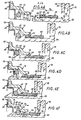
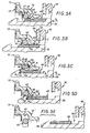
- la figure 1 est une vue partielle en coupe axiale d'un montage de butée de débrayage suivant l'invention ;
- la figure 2 reprend, à échelle supérieure, le détail de la figure 1 repéré par un encart II sur celle-ci ;
- la figure 3 est, à échelle différente, une vue en perspective du seul organe de découplage mis en oeuvre dans ce montage de butée de débrayage, représenté isolément ;
- les figures 4A, 4B, 4C, 4D, 4E, 4F sont des vues qui, reprenant celle de la figure 2, illustrent le couplage de la butée de débrayage concernée avec la pièce d'accostage portée par le dispositif débrayeur de l'embrayage à commander ;
- les figures 5A, 5B, 5C, 5D, 5E sont des vues qui, reprenant également celle de la figure 2, illustrent au contraire le découplage de cette butée de débrayage par rapport à cette pièce d'accostage ;
- les figures 6, 7, sont des vues partielles en coupe axiale analogues, elles aussi, à celle de la figure 2, et se rapportant chacune respectivement à une variante de réalisation.
- Figure 1 is a partial view in axial section of a clutch release bearing assembly according to the invention;
- Figure 2 shows, on a larger scale, the detail of Figure 1 identified by an insert II thereon;
- Figure 3 is, on a different scale, a perspective view of the single decoupling member used in this clutch release bearing assembly, shown in isolation;
- FIGS. 4A, 4B, 4C, 4D, 4E, 4F are views which, repeating that of FIG. 2, illustrate the coupling of the declutch release bearing concerned with the docking part carried by the clutch release device of the clutch. order;
- FIGS. 5A, 5B, 5C, 5D, 5E are views which, also taking that of FIG. 2, illustrate on the contrary the decoupling of this clutch release bearing with respect to this docking part;
- Figures 6, 7, are partial views in axial section similar, too, to that of Figure 2, and each relating respectively to an alternative embodiment.
Tel qu'illustré par la figure 1, il s'agit d'atteler une butée de débrayage 10 au dispositif débrayeur 11 d'un quelconque embrayage à commander.As illustrated in FIG. 1, this involves coupling a clutch release bearing 10 to the
Dans les formes de réalisation représentées, le dispositif débrayeur 11, qui n'a été que schématisé, en traits interrompus sur la figure 1, est, de manière connue en soi, formé par l'extrémité des doigts radiaux d'un diaphragme, c'est-à-dire d'une pièce annulaire, qui, appartenant à l'embrayage à commander, comporte une partie périphérique circulairement continue, formant rondelle Belleville, pour sollicitation en engagement de cet embrayage, et une partie centrale fragmentée en doigts radiaux par des fentes, à savoir les doigts radiaux en question, pour constitution de leviers propres à sa commande en dégagement.In the embodiments shown, the declutching
De manière également connue en soi, pour l'attelage de la butée de débrayage 10 au dispositif débrayeur 11, nécessaire à une action en traction de cette butée de débrayage 10 sur ce dispositif débrayeur 11, il est rapporté sur ce dernier, à la faveur de son ouverture centrale 12, une pièce 13, dite ici par commodité pièce d'accostage.In a manner also known per se, for the coupling of the declutching
Dans les formes de réalisation représentées, cette pièce d'accostage 13, ou pièce d'action, est du type de celle décrite dans la demande de brevet français déposée le 11 avril 1983, sous le No 83 05850, et publiée sous le No 2.544.036.In the embodiments shown, this
Une telle pièce d'accostage ne faisant pas partie de la présente invention, elle ne sera pas décrite en détail ici.Since such a docking part is not part of the present invention, it will not be described in detail here.
Il suffira d'indiquer que, du côté du dispositif débrayeur 11 opposé à la butée de débrayage 10, elle comporte radialement une collerette 14, dite collerette d'appui, pour action sur un tel dispositif débrayeur 11, ladite collerette d'appui étant convenablement profilée à cet effet, et que, d'un seul tenant avec cette collerette d'appui 14, elle comporte, d'une part, à sa périphérie interne, une douille 15, qui, s'étendant globalement axialement, traverse axialement ledit dispositif débrayeur 11, à la faveur de l'ouverture centrale 12 de celui-ci, et, d'autre part, à sa périphérie externe, de place en place le long de celle-ci, des pattes 16, qui traversent également axialement le dispositif débrayeur 11, chacune entre deux doigts radiaux adjacents de celui-ci, et qui, chacune respectivement, portent, circonférentiellement, en porte-à-faux, à leur extrémité, au droit de la collerette d'appui 14, et globalement parallèlement à celle-ci, des doigts de retenue 17 propres à assurer, en coopération avec cette collerette d'appui 14, le maintien axial de l'ensemble sur le dispositif débrayeur 11.It will suffice to indicate that, on the side of the declutching
Tel que décrit dans la demande de brevet français No 83 05850 mentionnée ci-dessus, la mise en place d'une telle pièce d'accostage 13 sur le dispositif débrayeur 11 se fait suivant un montage du type à baïonnette : après un rapprochement relatif suffisant de la pièce d'accostage 13 et du dispositif débrayeur 11, on assure, axialement, une flexion relative, vis-à-vis des autres, de l'extrémité de chacun des doigts radiaux du dispositif débrayeur 11 sur lequel doit circonférentiellement s'engager le doigt de retenue 17 des pattes 16 de la pièce d'accostage 13, puis on assure, circonférentiellement, une rotation relative, autour de l'axe de l'ensemble, de ladite pièce d'accostage 13 vis-à-vis dudit dispositif débrayeur 11, pour qu'un tel engagement ait effectivement lieu, et on libère ensuite les doigts radiaux précédemment fléchis du dispositif débrayeur 11.As described in the French patent application No. 83 05850 mentioned above, the installation of such a
Dans la forme de réalisation plus particulièrement représentée sur les figures 1 à 5, et pour des raisons qui apparaîtront ci-après, la douille axiale 15 de la pièce d'accostage 13, qui est en pratique en tôle convenablement conformée, présente, dans sa zone médiane, entre deux tronçons globalement rectilignes, un décrochement 18, celui de ses tronçons rectilignes qui est axialement le plus éloigné de sa collerette d'appui 14 ayant globalement un diamètre moindre que celui de l'autre.In the embodiment more particularly shown in Figures 1 to 5, and for reasons which will appear below, the
A son extrémité libre, c'est-à-dire à l'extrémité libre de son tronçon rectiligne de moindre diamètre, elle est, à sa périphérie interne, chanfreinée, et elle forme ainsi, pour des raisons qui apparaîtront également ci-après, une portée tronconique d'engagement 19.At its free end, that is to say at the free end of its rectilinear section of smaller diameter, it is, at its internal periphery, chamfered, and it thus forms, for reasons which will also appear below, a frustoconical scope of
La butée de débrayage 10 ne fait pas non plus, en soi, partie de la présente invention.The clutch release bearing 10 is also not, per se, part of the present invention.
De manière connue en soi, elle comporte, globalement, un élément d'attaque 20, par lequel elle est adaptée à agir sur le dispositif débrayeur 11, par l'intermédiaire de la pièce d'accostage 13, tel que détaillé ci-après, un élément de manoeuvre 22, par lequel elle est destinée, dans les formes de réalisation représentées, à être montée coulissante axialement sur un quelconque organe de guidage, non représenté, et des moyens d'attelage qui assujettissent axialement ledit élément d'attaque 20 audit élément de manoeuvre 22, et par lesquels, dans ces formes de réalisation, et tel que schématisé en traits interrompus sur la figure 1, elle est par ailleurs adaptée à être actionnée par un organe de commande 24, constitué, par exemple, par une fourchette de débrayage à doigts ou bras 21.In a manner known per se, it comprises, overall, a driving
Dans les formes de réalisation représentées, l'élément d'attaque 20 est constitué par un roulement à billes.In the embodiments shown, the driving
Pour coopération avec la pièce d'accostage 13, celui-ci comporte une pièce 25, dite ici par commodité pièce d'attaque.For cooperation with the
Dans les formes de réalisation représentées, cette pièce d'attaque 25 est constituée par la bague interne de ce roulement à billes, celle-ci étant suffisamment prolongée axialement à cet effet en direction du dispositif débrayeur 11.In the embodiments shown, this leading
Dans les formes de réalisation plus particulièrement représentées sur les figures 1 à 4, et également à la figure 6, cette bague interne est une pièce massive convenablement usinée.In the embodiments more particularly shown in Figures 1 to 4, and also in Figure 6, this inner ring is a solid piece suitably machined.
Conjointement, dans les formes de réalisation représentées, l'élément, de manoeuvre 22 comporte, axialement, un manchon 26, par lequel il est adapté à être engagé à coulissement sur l'organe de guidage associé, et, transversalement, à l'extrémité dudit manchon 26 opposée à l'élément d'attaque 20, pour coopération avec celui-ci, un flasque annulaire 27.Jointly, in the embodiments shown, the operating
A sa périphérie, ce flasque annulaire 27 porte lui-même, axialement en saillie, coaxialement par rapport au manchon 26 et dans le même sens que celui-ci, autour de la bague externe 29 du roulement à billes constituant l'élément d'attaque 20, une couronne 28.At its periphery, this
S'agissant, en pratique, dans les formes de réalisation représentées, d'une butée de débrayage autocentreuse à autocentrage maintenu, un jeu est laissé annulairement libre entre cette couronne 28 et le roulement à billes constituant l'élément d'attaque 20.As regards, in practice, in the embodiments shown, a self-centering declutching stop with self-centering maintained, a clearance is left annularly free between this
Les moyens d'attelage assujettissant axialement cet élément d'attaque 20 à l'élément de manoeuvre 22 sont constitués, dans les formes de réalisation représentées, par un capot 30, qui, par une jupe 31, est engagé sans jeu sur la couronne 28 de l'élément de manoeuvre 22.The coupling means axially securing this driving
A l'extrémité axiale de cette jupe 31 disposée du côté du dispositif débrayeur 11, le capot 30 présente, en direction de l'axe de l'ensemble, un bord tombé 33, contre lequel porte, par sa tranche correspondante, la bague externe 29 du roulement à billes constituant l'élément d'attaque 20, mais qui, pour des raisons qui apparaîtront ci-après, s'arrête largement à distance de la bague externe de celui-ci, en laissant subsister annulairement entre lui et celle-ci un espace libre E.At the axial end of this
A l'autre extrémité axiale de sa jupe 31, le capot 30, forme, pour l'action des doigts ou bras 21 de l'organe de commande 24, deux bras 34, qui, en positions diamétralement opposées l'un par rapport à l'autre, s'étendent radialement en saillie en direction opposée à l'axe de l'ensemble.At the other axial end of its
Pour des raisons qui apparaîtront ci-après, ces bras 34 présentent chacun, parallèlement à l'axe de l'ensemble, et en direction du dispositif débrayeur 11, un retour en équerre 35, par lequel ils contournent les bras ou doigts 21 de l'organe de commande 24, et, en bout de ce retour en équerre 35, parallèlement à eux-mêmes, et en direction dudit axe de l'ensemble, une patte 36.For reasons which will appear below, these
A la figure 1, un tel retour en équerre 35 et une telle patte 36 ne sont visibles que pour l'un des bras 34 concernés.In FIG. 1, such a return to square 35 and such a
Bien entendu, il est prévu, entre le capot 30 ainsi constitué et l'élément de manoeuvre 22, des moyens propres à assujettir axialement ce capot 30 à cet élément de manoeuvre 22.Of course, there are provided, between the
Il peut s'agir, par exemple, de moyens d'encliquetage, des pattes élastiquement déformables étant prévues à cet effet dans la couronne 28 de l'élément de manoeuvre 22 pour coopération avec des ouvertures également prévues à cet effet dans la jupe 31 du capot 30.It may be, for example, latching means, elastically deformable tabs being provided for this purpose in the
Ces dispositions sont bien connues par elles-mêmes, notamment par la demande de brevet français qui, déposée le 18 juin 1981 sous le No 81 12001, a été publiée sous le No 2.508.125, et ne faisant pas en soi partie de la présente invention, elles ne seront pas décrites plus en détail ici.These provisions are well known in themselves, in particular by the French patent application which, filed on June 18, 1981 under No. 81 12001, was published under No. 2.508.125, and not being in itself part of this invention, they will not be described in more detail here.
De même, s'agissant, en pratique, comme déjà indiqué ci-dessus, d'une butée de débrayage autocentreuse à autocentrage maintenu, il est prévu, entre l'élément d'attaque 20 et l'élément de manoeuvre 22, des moyens élastiques à action axiale, constitués, par exemple, tel que représenté, par une rondelle ondulée 37 du type de celle vendue sous la dénomination commerciale "ONDUFLEX".Likewise, being, in practice, as already indicated above, a self-centering clutch release bearing with self-centering maintained, there is provided, between the driving
Dans les formes de réalisation représentées, cette rondelle ondulée 37 prend appui sur le flasque annulaire 27 de l'élément de manoeuvre 22, et elle porte sur la tranche correspondante de la bague externe 29 du roulement à billes constituant l'élément d'attaque 20, pour sollicitation de cette bague externe contre le bord tombé 33 du capot 30.In the embodiments shown, this corrugated washer 37 bears on the
De manière connue en soi, entre la pièce d'attaque 25 de la butée de débrayage.10 ainsi constituée, d'une part, et la pièce d'accostage 13 portée par le dispositif débrayeur 11, d'autre part, sont établis des moyens de solidarisation en traction propres à assurer une liaison axiale entre lesdites pièces dans le sens axial qui, tel que schématisé par la flèche F1 sur la figure 1, va du dispositif débrayeur 11 à la butée de débrayage 10.In a manner known per se, between the leading
La pièce d'accostage 13 comportant axialement une douille 15, et celle-ci étant coaxiale de la pièce d'attaque 25, c'est entre cette douille 15 et cette pièce d'attaque 25 que sont établis lesdits moyens de solidarisation en traction.The
Plus précisément, dans les formes de réalisation représentées, la pièce d'attaque 25 est engagée dans la douille 15 de la pièce d'accostage 13, en sorte que les moyens de solidarisation en traction en question interviennent entre la périphérie externe de cette pièce d'attaque 25 et la périphérie interne de cette douille 15.More precisely, in the embodiments shown, the leading
D'une manière générale, ils comportent, figures 1 et 2, d'une part, un organe annulaire de couplage 42, qui est élastiquement déformable radialement, et qui est au moins partiellement engagé radialement dans une gorge annulaire de retenue 43 ménagée pour lui sur l'une des pièces 13, 25 en cause, et, d'autre part, une portée d'entraînement 44, qui est ménagée globalement transversalement sur l'autre desdites pièces 13, 25, et avec laquelle il est apte à coopérer axialement en appui dans le sens axial considéré, celui repéré par la flèche F1 sur la figure 1.In general, they comprise, Figures 1 and 2, on the one hand, an
De manière également connue en soi, il est prévu, en outre, un organe de découplage 46, monté mobile axialement dans une gorge 47, qui est ménagée pour lui sur celle des pièces 13, 25 comportant la portée d'entraînement 44, et dont ladite portée d'entraînement 44 appartient à l'un des flancs.In a manner also known per se, there is further provided a
Suivant l'invention, l'organe de couplage 42 étant porté par la pièce d'accostage 13, et l'organe de découplage 46 par la pièce d'attaque 25 de la butée de débrayage 10, ledit organe de découplage 46 comporte, tel que détaillé ci-après, des moyens d'engagement propres à en permettre l'accouplement débrayables avec ledit organe de couplage 42, au moins pour le sens axial allant du dispositif débrayeur 11 à ladite butée de débrayage 10.According to the invention, the
Ainsi donc, la gorge de retenue 43 prévue pour l'organe de couplage 42 est ménagée dans la pièce d'accostage 13, et la gorge 47 prévue corollairement pour l'organe de découplage 46 est ménagée sur la pièce d'attaque 25 de la butée de débrayage 10.Thus, the retaining
Dans la forme de réalisation plus particulièrement représentée sur les figures 1 à 5, la gorge de retenue 43 est formée entre le décrochement 18 que présente la douille axiale 15 de la pièce d'accostage 13 et une pièce 49 rapportée sur celle-ci.In the embodiment more particularly shown in Figures 1 to 5, the retaining
Par exemple, et tel que représenté, cette pièce 49 est simplement crochetée par des pattes 50 sur la pièce d'accostage 13, du côté de celle-ci opposé au dispositif débrayeur 11, dans la région du coude que forment entre elles sa collerette d'appui 14 et sa douille axiale 15, lesdites pattes 50 traversant cette collerette d'appui 14 à la faveur des entailles ménagées dans celle-ci pour la formation des pattes 16 associées et étant, au-delà, rabattues au contact de sa face opposée.For example, and as shown, this
Quoi qu'il en soit, cette pièce 49, qui se présente globalement sous la forme d'une cuvette à fond 52 largement ajouré par une ouverture centrale 53 dont le diamètre est sensiblement le même que celui de la périphérie interne du tronçon rectiligne de plus petit diamètre de la douille axiale 15 de la pièce d'accostage 13 ; par sa paroi latérale 54 elle est appliquée contre le tronçon rectiligne de plus grand diamètre de ladite douille axiale 15 ; et par un rebord 55, qui est radialement dirigé en direction opposée à l'axe de l'ensemble, et dont les pattes 50 forment, de place en place, des prolongements, elle est appliquée contre la collerette d'appui 14.Anyway, this
Le fond 52 de la pièce 49 ainsi constituée s'étend radialement en direction de l'axe de l'ensemble et il fait face au décrochement 18 de la douille axiale 15.The bottom 52 of the
Il forme donc celui, 57, des flancs de la gorge de retenue 43 qui est tourné axialement dans le même sens que la portée d'entrainement 44.It therefore forms that, 57, of the sides of the retaining
Autrement dit, dans les formes de réalisation en cause, ce flanc 57 de la gorge de retenue 43 appartient à une pièce, à savoir la pièce 49, qui, distincte de la pièce d'accostage 13, est solidaire de celle-ci.In other words, in the embodiments in question, this
En pratique, ce flanc 57 est droit.In practice, this
Par contre, et pour des raisons qui apparaîtront ci-après, l'autre, 58, des flancs de la gorge de retenue 43, c'est-à-dire celui de ses flancs qui, formé par le décrochement 18 de la douille axiale 15, est opposé à la portée d'entraînement 44, présente, dans les formes de réalisation représentées, à compter du fond de cette gorge de retenue 43, une première portée tronconique 59, et, faisant suite à celle-ci, une deuxième portée tronconique 60, qui est de conicité plus faible que celle de la précédente, et qui s'étend en pratique jusqu'à la périphérie interne du tronçon rectiligne de moindre diamètre de la douille axiale 15.By cons, and for reasons which will appear below, the other, 58, flanks of the retaining
Ainsi donc, dans les formes de réalisation représentées, du côté de son flanc 58, la gorge de retenue 43 va en s'évasant vers l'extérieur, de son fond vers la périphérie externe de la pièce d'attaque 25.Thus, in the embodiments shown, on the side of its
En pratique, dans les formes de réalisation représentées, l'organe de couplage 42 est formé par un simple jonc.In practice, in the embodiments shown, the
Autrement dit, il s'agit d'une pièce de forme générale torique, et, dans les formes de réalisation représentées, celle-ci a, axialement, une section transversale circulaire.In other words, it is a part of generally toroidal shape, and, in the embodiments shown, this has, axially, a circular cross section.
L'élasticité que présente radialement cet organe de couplage 42 peut résulter de la seule nature de la matière qui le constitue.The elasticity that this
En variante, elle peut résulter d'une fente qui l'affecte radialement, le jonc qu'il forme étant par exemple réalisé par simple roulage d'un fil rond.As a variant, it may result from a slit which affects it radially, the rod that it forms being for example produced by simple rolling of a round wire.
Quoi qu'il en soit, à l'état libre, figure 4A, l'organe de couplage 42 occupe une configuration rétractée pour laquelle son diamètre extérieur D1 est supérieur à celui D2 de la périphérie externe du tronçon rectiligne de moindre diamètre de la douille axiale 15 de la pièce d'attaque 13.Anyway, in the free state, Figure 4A, the
Mais, du fait de son élasticité, il peut prendre une configuration déployée, figure 4D par exemple, pour laquelle son engagement radial dans la gorge de retenue 43 est accentué.However, due to its elasticity, it can take a deployed configuration, FIG. 4D for example, for which its radial engagement in the retaining
Dans les formes de réalisation représentées, l'organe de découplage 46 se présente, lui, sous la forme générale d'un anneau relativement plat, c'est-à-dire d'un anneau dont la section radiale est allongée parallèlement à son axe.In the embodiments shown, the
Du côté axialement opposé à la portée d'entraînement 44, il a, transversalement, un profil droit.On the side axially opposite to the
Par contre, celle de ses extrémités axiales qui est dirigée vers la portée d'entraînement 44 est chanfreinée, à sa périphérie externe, par une portée tronconique d'engagement 62.On the other hand, that of its axial ends which is directed towards the
Ainsi donc, du côté de la portée d'entraînement 44, l'organe de découplage 46 a un profil globalement triangulaire.Thus, on the side of the
Comme pour l'organe de couplage 42, l'élasticité radiale de l'organe de découplage 46 peut résulter de la seule nature de sa matière constitutive.As for the
Mais, tel que représenté, elle peut aussi bien résulter d'une fente 63 l'affectant radialement.But, as shown, it may as well result from a
De préférence, au repos, les lèvres de cette fente 63 sont au contact l'une de l'autre, et il subsiste, entre l'organe de découplage 46 et le fond de la gorge 47 dans laquelle il est disposé, un jeu annulaire J, figure 2.Preferably, at rest, the lips of this
Dans les formes de réalisation plus particulièrement représentées sur les figures 1 à 6, les moyens d'engagement prévus sur l'organe de découplage 46 pour son accouplement débrayable avec l'organe de couplage 42 sont formés par au moins une languette 64, dite ici par simple commodité languette d'entraînement, que ledit organe de découplage 46 présente axialement, et qui est élastiquement déformable radialement, avec, au repos, une extrémité libre 65 qui fait saillie sur la périphérie externe de cet organe de découplage 46.In the embodiments more particularly shown in Figures 1 to 6, the engagement means provided on the
Au repos, l'extrémité libre 65 de cette languette d'entraînement 64 s'étend sur une circonférence de diamètre D3 légèrement supérieur à celui D2 de la périphérie interne du tronçon rectiligne de moindre diamètre de la douille axiale 15 de la pièce d'accostage 13, figure 4A.At rest, the
Bien entendu, l'organe de découplage 46 comporte ainsi, convenablement réparties circulairement, plusieurs languettes d'entraînement 64 identiques.Of course, the
Elles sont d'un seul tenant avec l'organe de découplage 46 qu'elles équipent, et, à compter de leur zone d'enracinement à celui-ci, elles s'étendent axialement en direction de la portée d'entraînement 44.They are in one piece with the
L'organe de couplage 42 étant formé, comme indiqué ci-dessus, par un simple jonc dans les formes de réalisation représentées, chacune d'elles a, axialement, au voisinage de son extrémité libre 65, dans ces formes de réalisation, un profil au moins en partie complémentaire de celui dudit organe de couplage 42, et donc, en pratique, au moins en partie circulaire.The
Dans la forme de réalisation plus particulièrement représentée sur les figures 1 à 5, les languettes d'entraînement 64 sont au nombre de six, et elles alternent avec des pattes axiales 67, qui forment la partie courante correspondante de l'organe de découplage 46, et dont elles sont chacune séparées latéralement par des fentes 68.In the embodiment more particularly shown in FIGS. 1 to 5, there are six
Ces pattes 67, comme les languettes d'entraînement 64, sont issues d'une portion massive 69 de l'organe de découplage 46, et, par rapport à celle-ci, elles s'étendent axialement au-delà de l'extrémité libre 65 desdites pattes d'entraînement 64.These
Ainsi donc, dans la forme de réalisation représentée sur les figures 1 à 5,.les languettes d'entraînement 65 sont, axialement, tout entières contenues dans le contour hors tout de l'organe de découplage 46.Thus, in the embodiment shown in FIGS. 1 to 5, .the
Par ailleurs, dans cette forme de réalisation, c'est à l'extrémité axiale des pattes 67 qu'est formée la portée tronconique d'engagement 62 de l'organe de découplage 46.Furthermore, in this embodiment, it is at the axial end of the
Ainsi donc, dans la forme de réalisation plus particulièrement représentée sur les figures 1 à 5, cette portée tronconique d'engagement 62 appartient à une portion de l'organe de découplage 46, qui, distincte des languettes d'entraînement 64, s'étend axialement entre l'extrémité libre 65 de ces languettes d'entraînement 64 et la portée d'entraînement 44.Thus, in the embodiment more particularly shown in FIGS. 1 to 5, this
En outre, dans cette forme de réalisation, l'organe de découplage 46 présente, transversalement, dans sa zone médiane, à distance de l'extrémité libre 65 des languettes d'entraînement 64, et axialement tourné vers ladite extrémité libre 65 de celles-ci, un épaulement 70.In addition, in this embodiment, the
Dans la forme de réalisation représentée, cet épaulement 70, qui affecte la périphérie externe de l'organe de découplage 46, s'étend sensiblement au droit de la zone d'enracinement des languettes d'entraînement 64 et des pattes axiales 67 à la portion massive 69 de cet organe de découplage 46, en sorte que cette dernière a, radialement, une épaisseur supérieure à celle dans laquelle sont formées lesdites languettes d'entraînement 64 et lesdites pattes axiales 67.In the embodiment shown, this
En outre, il. s'agit d'un épaulement globalement tronconique.Furthermore, it. it is a generally frustoconical shoulder.
Quoi qu'il en soit, l'épaississement auquel il conduit pour une position de l'organe de découplage 46 renforce avantageusement celui-ci.Anyway, the thickening to which it leads for a position of the
Enfin, dans le cas où, tel que représenté, l'organe de découplage 46 est réalisé en matière synthétique, par moulage d'une telle matière, il comporte, à sa périphérie externe, au droit de ses languettes d'entraînement 64, des saignées 73 entaillant axialement en surface sa portion massive 69, pour le passage des poinçons propres à la formation de l'extrémité libre 65 de ces languettes d'entraînement 64.Finally, in the case where, as shown, the
Du côté axialement opposé à la portée d'entrainement 44, la gorge 47 dans laquelle est monté mobile axialement l'organe de découplage 46 ainsi constitué a, dans la forme de réalisation représentée, un flanc droit 75, à l'image de celui, correspondant, dudit organe de découplage 46.On the side axially opposite to the
Mais, à la racine de celui de ses flancs-auquel appartient la portée d'entrainement 44, cette gorge 47 présente, dans la forme de réalisation représentée, un dégagement 76 de profil propre à y permettre une pénétration au moins partielle de l'organe de découplage 46.But, at the root of that of its flanks-to which the
Dans la forme de réalisation représentée, ce profil est donc globalement triangulaire, à l'image de celui, correspondant, de l'organe de découplage 46.In the embodiment shown, this profile is therefore generally triangular, like the corresponding one of the
Le dégagement 76 que présente ainsi, à la manière d'une simple piqure-, la gorge 47, se raccorde à la portée d'entraînement 44, et, en liaison avec le bord libre de celle-ci, la pièce d'attaque 25 de la butée de débrayage 10 comporte, sur sa périphérie externe, une portée cylindrique 77 laissant une épaisseur suffisante de matière entre elle et un tel dégagement 76.The
Cette portée cylindrique est elle-même en liaison avec une portée tronconique d'engagement 78 que présente, à sa périphérie externe, ladite pièce d'attaque 25, à son extrémité axiale libre.This cylindrical bearing is itself in connection with a frustoconical engagement bearing 78 which has, at its outer periphery, said engaging
La portée cylindrique 77 de la pièce d'attaque 25, qui est à niveau avec la partie courante de la périphérie externe de celle-ci, a, en pratique, un·diamètre D4 légèrement inférieur à celui D2 de la périphérie interne du tronçon de moindre diamètre de la douille axiale 15 de la pièce d'accostage 13, figure 4A.The
Cette pièce d'accostage 13 est équipée par avance de l'organe de couplage 42, dans la gorge de retenue 43 qu'elle forme avec la pièce 49 qui en est solidaire, et, d'ailleurs, cet organe de couplage 42 peut occuper axialement une place quelconque dans cette gorge de retenue 43, figure 4A.This
De même, la pièce d'attaque 25 de la butée de débrayage 10 est équipée par avance de l'organe de découplage 46, dans sa gorge 47, et celui-ci y occupe axialement une place quelconque.Likewise, the leading
Par exemple, et tel que représenté à la figure 4A, on supposera ci-après que l'organe de découplage 46 est en position avancée dans cette gorge 47, celle de ses extrémités axiales qui comporte la portée tronconique d'engagement 62 étant engagée dans le dégagement 76 présent à la racine du flanc de ladite gorge 47 auquel appartient cette portée d'entraînement 44.For example, and as shown in FIG. 4A, it will be assumed below that the
Pour l'attelage de l'ensemble, la butée de débrayage 10 est engagée axialement, par sa pièce d'attaque 25, dans la douille axiale 15 de la pièce d'accostage 13, tel que schématisé par la flèche F2 sur la figure 4A.For coupling the assembly, the clutch release bearing 10 is engaged axially, by its leading
Si, comme indiqué, l'organe de découplage 46 est alors en position avancée, les languettes d'entraînement 64 de cet organe de découplage 46 viennent, au cours de cet engagement axial, buter par leur extrémité libre 65 contre la portée tronconique d'engagement 19 de la pièce d'accostage 13, figure 4B, en sorte que, ainsi arrêté par rapport à la butée de débrayage 10, l'organe de découplage 46 se déplace dans la gorge 47 de celle-ci en direction de l'extrémité axiale de cette gorge 47 opposée à la portée d'entraînement 44.If, as indicated, the
Conjointement, le mouvement axial d'engagement de la butée de débrayage 10 étant poursuivi, la pièce d'attaque 25 de celle-ci vient porter, par sa portée tronconique d'engagement 78, contre l'organe de couplage 42, figure 4C, ce qui contraint peu à peu celui-ci à s'effacer élastiquement à l'intérieur de la gorge de retenue 43 de la pièce d'accostage 13.At the same time, the axial engagement movement of the clutch release bearing 10 being continued, the leading
A un certain moment, figure 4D, la pièce d'attaque 25 de la butée de débrayage 10 vient à nouveau entraîner, par son extrémité axiale opposée à la portée d'entraînement 44, l'organe de découplage 46, ce qui contraint les languettes d'entraînement 64 de celui-ci à s'engager dans le tronçon de moindre diamètre de la douille axiale 15 de la pièce d'accostage 13, avec un fléchissement élastique radial desdites languettes d'entraînement 64 en direction de l'axe de l'ensemble.At a certain moment, in FIG. 4D, the leading
Par ailleurs, au cours de ce mouvement axial d'engagement de la butée de débrayage 10 étant poursuivi, la pièce d'attaque 25 de celle-ci s'engage par sa portée cylindrique 77 dans l'organe de couplage 42, figure 4D.Furthermore, during this axial movement of engagement of the clutch release bearing 10 being continued, the leading
Bien entendu, cette phase peut intervenir simultanément avec la précédente, ou avant ou après celle-ci.Of course, this phase can occur simultaneously with the previous one, or before or after it.
Quoi qu'il en soit, une fois franchie la portée d'entraînement 44, l'organe de couplage 42, ainsi libéré, tend à reprendre, à la faveur de la gorge 47 de la pièce d'attaque 25, sa configuration rétractée initiale, et, le cas échéant, tel que représenté, figure 4E, il vient donc porter contre le fond de cette gorge 47.Anyway, once crossed the
Mais, en variante, il peut aussi bien demeurer à distance de celui-ci.But, as a variant, it may as well remain at a distance therefrom.
Bien entendu, la rétraction de l'organe de couplage 42 intervient dès que la portée d'entraînement 44 l'a franchi.Of course, the retraction of the
Mais, en pratique, et tel que le schématise le jeu apparaissant à la figure 4E entre cet organe de couplage 42 et la portée d'entraînement 44, le mouvement axial d'engagement imprimé à la butée de débrayage 10 est volontairement prolongé d'une surcourse, pour être sûr que cette portée d'entraînement 44, qui appartient à la pièce d'attaque 25 de cette butée de débrayage 10, a bien ainsi franchi l'organe de couplage 42, et que celui-ci, ainsi libéré, a pu s'engager dans la gorge 47 de cette pièce d'attaque 25.However, in practice, and as shown schematically the clearance appearing in FIG. 4E between this coupling
Quoi qu'il en soit, du fait du recul préalablement imprimé, si nécessaire, et suivant le processus décrit ci-dessus, dans cette gorge 47, à l'organe de couplage 46, par les languettes d'entraînement 64 de celui-ci, c'est en toute certitude que, quelle que soit la position initiale de cet organe de découplage 46 dans cette gorge 47, la place est libre dans celle-ci pour l'organe de couplage 42 au voisinage immédiat de la portée d'entraînement 44.Anyway, due to the previously printed recoil, if necessary, and according to the process described above, in this
Il suffit donc, ensuite, pour l'attelage recherché, d'inverser, suivant la flèche F3 de la figure 4F, le mouvement axial imprimé à la butée de débrayage 10.It is therefore sufficient, then, for the desired coupling, to reverse, along the arrow F3 in FIG. 4F, the axial movement imparted to the clutch release bearing 10.
La pièce d'attaque 25 de l'élément d'attaque 20 de celle-ci vient alors porter contre l'organe de couplage 42 par sa portée d'entraînement 44, et, refoulant cet organe de couplage 42 en direction du flanc 58 de la gorge de retenue 43, elle vient l'appliquer axialement contre celle-ci, et, plus précisément, contre sa portée tronconique de plus faible conicité 60.The driving
L'attelage, ou couplage, recherché, est alors assuré : si, suivant la flèche F1 de la figure 1, qui correspond à la flèche F3 de la figure 4F, une action de traction est exercée sur la butée de débrayage 10 par l'organe de commande 24, cette action de traction est transmise au dispositif débrayeur 11 à travers successivement l'organe de couplage 42, par la portée d'entraînement 44, et la pièce d'accostage 13, par la portée tronconique 60 du flanc 58 de la gorge de retenue 43.The desired coupling, or coupling, is then ensured: if, according to arrow F1 in FIG. 1, which corresponds to arrow F3 in FIG. 4F, a traction action is exerted on the clutch release bearing 10 by the
Ainsi qu'il est aisé de le comprendre, le mouvement axial qu'il est nécessaire d'appliquer à la butée de débrayage 10, d'abord dans un sens, puis dans l'autre, pour un tel couplage, peut avantageusement lui être imprimé en aveugle à l'aide de l'organe de commande 24, les doigts 21 de celui-ci agissant d'abord sur les pattes 36 de son capot 30, puis sur les bras 34 de ce capot 30 dont les pattes 36 précédentes forment un prolongement.As is easy to understand, the axial movement which it is necessary to apply to the release bearing 10, first in one direction, then in the other, for such coupling, can advantageously be printed blind using the
Il en est de même pour le découplage.The same is true for decoupling.
Dans un premier temps, et suivant la flèche F4 de la figure 5A, il est procédé à nouveau à un engagement axial de la butée de débrayage 10 dans la douille 15 de la pièce d'accostage 13, en sorte que, repoussé par l'organe de découplage 46, l'organe de couplage 42 vient buter contre le flanc 57 de la gorge de retenue 43, et que, le mouvement d'engagement axial de la butée de débrayage 10 étant poursuivi, cet organe de découplage 46 s'engage dans l'organe de couplage 42, moyennenant une déformation radiale élastique de celui-ci.Firstly, and in the direction of arrow F4 in FIG. 5A, an axial engagement of the clutch release bearing 10 is again carried out in the
D'abord limité à son extrémité axiale, cet engagement de l'organe de découplage 46 dans l'organe de couplage 42 s'étend ensuite à l'extrémité libre 65 de ses languettes d'entraînement 64, par déformation élastique radiale de celles-ci en direction de l'axe de l'ensemble, lesdites languettes d'entrainement 64 retrouvant ensuite par élasticité leur configuration initiale après franchissement de l'organe de couplage 42, figure 5B.First limited to its axial end, this engagement of the
Conjointement, et ainsi qu'on le notera, le tronçon de moindre diamètre de la douille axiale 15 de la pièce d'accostage 13 s'est engagé dans l'espace libre E ménagé entre le bord tombé 33 du capot 30 et la pièce d'attaque 25.At the same time, and as will be noted, the section of smaller diameter of the
Quoi qu'il en soit, par les languettes d'entraînement 64 de l'organe de découplage 46, l'organe de couplage 42 se trouve dès lors accouplé, mais de manière débrayable, à cet organe de découplage 46, au moins dans le sens axial allant du dispositif débrayeur 11 à la butée de débrayage 10.Anyway, by the
Si, donc, il est imprimé à la butée de débrayage 10, suivant la flèche F5 de la figure 5C, un mouvement axial inverse du précédent, la pièce d'attaque 25 de cette butée de débrayage 10 vient entrainer, par celui des flancs de sa gorge 47 auquel appartient la portée d'entrainement 44, l'équipage formé conjointement par l'organe de découplage 46 et l'organe de couplage 42 en prise avec celui-ci, jusqu'à ce que, tel que représenté, cet organe de couplage 42 vienne buter contre le flanc 58 de la gorge de retenue 43 de la pièce d'accostage 13 opposé à ladite portée d'entrainement 44.If, therefore, it is printed at the clutch release bearing 10, along arrow F5 in FIG. 5C, an axial movement opposite to the previous one, the leading
Or, quand l'organe de couplage 42 est ainsi en prise avec l'organe de découplage 46, c'est par la portée tronconique de plus forte conicité 59 de ce flanc 58 que la pièce d'attaque 13 porte alors sur l'organe de couplage 42.However, when the
Par construction, la conicité de cette portée tronconique 59 est telle que, lorsque, comme indiqué, l'organe de découplage 46 est en butée contre celui des flancs de la gorge 47 auquel appartient la portée d'entraînement 44, la normale N à cette portée tronconique 59 s'étend à l'écart des moyens d'engagement associés, et, donc, en l'espèce, à l'écart de l'extrémité libre-65 des languettes d'entraînement 64 de l'organe de découplage 46.By construction, the taper of this
De préférence, et tel que représenté, cette normale N s'étend même également à l'écart de la gorge 47.Preferably, and as shown, this normal N even extends also away from the
Quoi qu'il en soit, si le mouvement axial en cours de la butée de débrayage 10 est poursuivi, figure 5D, il résulte de cette disposition que la sollicitation dont est l'objet l'organe de couplage 42 de la part de la pièce d'attaque 25 conduit cet organe de couplage 42 à échapper à l'organe de découplage 46.Anyway, if the axial movement in progress of the clutch release bearing 10 is continued, FIG. 5D, it results from this arrangement that the stress which is the object of the
Il ne peut dès lors que prendre contact avec la portée cylindrique 77 de la pièce d'attaque 25 de la butée de débrayage 10, figure 5D.It can therefore only make contact with the
Ainsi qu'on le comprendra, la prise de contact de l'organe de couplage 42 avec cette portée cylindrique 77 se trouve facilitée, d'une part, par le fait que, par l'engagement de l'organe de découplage 46 dans le dégagement 76 prévu dans la gorge 47 à la base de la portée d'entraînement 44, l'intervalle séparant axialement l'extrémité libre 65 des languettes d'entraînement 64 de l'organe de découplage 46 de cette portée cylindrique 77 se trouve avantageusement réduit, et, d'autre part, par le fait que la normale N précisée ci-dessus s'étend elle aussi préférentiellement à l'écart de cette gorge 47.As will be understood, the contacting of the
Le mouvement axial en cours de la butée de débrayage 10 étant poursuivi, l'organe de couplage 42 échappe alors à la pièce d'attaque 25, figure 5E.The axial movement in progress of the clutch release bearing 10 being continued, the
Le découplage recherché est ainsi assuré.The desired decoupling is thus ensured.
Mais un nouveau couplage est possible, suivant le processus précédemment décrit.But a new coupling is possible, according to the process previously described.
Ainsi donc, il est possible, suivant l'invention, d'assurer de manière réversible un tel couplage et un tel découplage.Thus, it is possible, according to the invention, to provide such a coupling and such a decoupling in a reversible manner.
A chaque fois il y a, suivant le processus décrit, un accouplement débrayable de l'organe de couplage avec l'organe de découplage, suivi de leur désacouplement, et, en pratique, dans la forme de réalisation représentée, cet accouplement est propre aussi bien à un entraînement de l'ensemble dans le sens axial allant du dispositif débrayeur de l'embrayage concerné à la butée de débrayage que dans le sens axial opposé, même s'il n'est opérationnel que dans le premier de ces sens.Each time there is, according to the process described, a disengageable coupling of the coupling member with the decoupling member, followed by their uncoupling, and, in practice, in the embodiment shown, this coupling is also clean well to a drive of the assembly in the axial direction from the disengaging device of the clutch concerned to the clutch release bearing only in the opposite axial direction, even if it is operational only in the first of these directions.
Dans la variante de réalisation schématiquement représentée à la figure 6, la portée tronconique d'engagement 62 de l'organe de découplage 46 appartient à l'extrémité libre de ses languettes d'entrainement 64.In the variant embodiment shown diagrammatically in FIG. 6, the
En pratique, dans la forme de réalisation représentée, la portion correspondante de l'organe de découplage 46 se réduit à ces languettes d'entrainement 64, sans de quelconques pattes axiales entre celles-ci.In practice, in the embodiment shown, the corresponding portion of the
Quoi qu'il en soit, les languettes d'entrainement 64 sont aptes à passer élastiquement d'une configuration déployée, qui est schématisée en traits interrompus sur la figure, et pour laquelle elles sont aptes à venir en butée contre la portée tronconique d'engagement 19 de la pièce d'accostage 13 lors de l'engagement axial dans celle-ci de la pièce d'attaque 25 de la butée de débrayage 10, à une configuration rétractée, qui est représentée en trait plein sur la figure, et pour laquelle elles sont aptes à venir s'engager dans l'organe de couplage 42, pour le déploiement de celui-ci qui, suivant le processus décrit précédemment, est nécessaire au découplage.Anyway, the
Ainsi qu'on le notera, dans la forme de réalisation représentée, la pièce d'attaque 25, au lieu d'être une pièce massive convenablement usinée, est une pièce en tôle convenablement conformée.As will be noted, in the embodiment shown, the
Corollairement, au lieu d'être une pièce en tôle convenablement conformée, la pièce d'accostage 13 est, dans la forme de réalisation représentée, une pièce massive convenablement usinée.As a corollary, instead of being a sheet metal part suitably shaped, the
Il en est de même dans la variante de réalisation illustrée à la figure 7.The same is true in the variant embodiment illustrated in FIG. 7.
En outre, dans celle-ci, les moyens d'engagement prévus pour permettre l'accouplement débrayable de l'organe de découplage 46 avec l'organe de couplage 42 sont formés par une rainure 80 que comporte annulairement, sur sa périphérie externe, cet organe de découplage 46.In addition, therein, the engagement means provided to allow the disengageable coupling of the
De préférence, mais non obligatoirement, cette rainure 80 a un profil au moins en partie complémentaire de celui de l'organe de couplage 42, et donc un profil au moins en partie circulaire.Preferably, but not necessarily, this
En variante, ce profil peut être différent, et par exemple quadrangulaire.As a variant, this profile may be different, and for example quadrangular.
Par ailleurs, si la portée tronconique d'engagement 62 de l'organe de découplage 46 se raccorde alors directement, par une arête 81, à la rainure 80, dans la forme de réalisation représentée, une portée cylindrique peut aussi bien être prévue entre elle et celle-ci.Furthermore, if the
Enfin, comme précédemment, l'organe de découplage 46 présente, axialement, au moins une languette d'entraînement 64, et, en pratique, une pluralité de telles languettes d'entraînement 64, qui sont élastiquement déformables radialement, et dont l'extrémité libre 65, au repos, fait radialement saillie sur sa périphérie externe.Finally, as before, the
De préférence, et tel que représenté, cette extrémité libre 65 des languettes d'entraînement 64 est axialement à distance de la rainure 80, en s'étendant du côté de cette rainure opposé à la portée d'entraînement 44.Preferably, and as shown, this
Ainsi qu'on le notera, les languettes d'entraînement 64, qui, comme précédemment, sont d'un seul tenant avec l'organe de découplage 46, en alternant avec des pattes axiales 67 de celui-ci, sont, axialement, tout entières contenues dans le contour hors tout de cet organe de découplage 46.As will be noted, the
Le fonctionnement de cette variante de réalisation est en tout point semblable à celui décrit précédemment.The operation of this alternative embodiment is in all respects similar to that described above.
Cependant, lorsque l'organe de couplage 42 est en prise avec l'organe de découplage 46, il est engagé radialement dans la rainure 80 de celui-ci.However, when the
La présente invention ne se limite d'ailleurs pas aux formes de réalisation décrites et représentées, mais englobe toute variante d'exécution et/ou de combinaison de leurs divers éléments. En particulier, dans une variante de réalisation non représentée l'organe de découplage, au lieu d'être ouvert par une fente pour sa mise en place sur la pièce d'attaque qu'il doit équiper, peut présenter, régulièrement réparties le long de l'une et l'autre de ses tranches axiales d'extrémité, des échancrures, qui, circulairement alternées de l'une à l'autre de ces tranches, sont axialement imbriquées de l'une à l'autre de celles-ci.The present invention is moreover not limited to the embodiments described and shown, but encompasses any variant embodiment and / or combination of their various elements. In particular, in a variant embodiment not shown, the decoupling member, instead of being opened by a slot for its positioning on the attack piece which it must equip, may have, regularly distributed along one and the other of its axial end sections, notches, which, circularly alternated from one to the other of these sections, are axially nested from one to the other of these.
Claims (23)
Applications Claiming Priority (2)
| Application Number | Priority Date | Filing Date | Title |
|---|---|---|---|
| FR8514934 | 1985-10-09 | ||
| FR8514934A FR2588338B1 (en) | 1985-10-09 | 1985-10-09 | ASSEMBLY OF REVERSIBLE CLUTCH STOPPER WITH DECOUPLING MEMBER ON THE CLUTCH STOPPER, PARTICULARLY FOR A MOTOR VEHICLE |
Publications (2)
| Publication Number | Publication Date |
|---|---|
| EP0224393A1 true EP0224393A1 (en) | 1987-06-03 |
| EP0224393B1 EP0224393B1 (en) | 1989-12-27 |
Family
ID=9323661
Family Applications (1)
| Application Number | Title | Priority Date | Filing Date |
|---|---|---|---|
| EP86402201A Expired EP0224393B1 (en) | 1985-10-09 | 1986-10-06 | Disengageable clutch release bearing assembly with a disconnecting element on the release bearing, especially for an automotive vehicle |
Country Status (7)
| Country | Link |
|---|---|
| US (1) | US4733762A (en) |
| EP (1) | EP0224393B1 (en) |
| JP (1) | JPS6293523A (en) |
| BR (1) | BR8604904A (en) |
| DE (1) | DE3667825D1 (en) |
| ES (1) | ES2012350B3 (en) |
| FR (1) | FR2588338B1 (en) |
Cited By (2)
| Publication number | Priority date | Publication date | Assignee | Title |
|---|---|---|---|---|
| EP2455633A1 (en) * | 2010-11-23 | 2012-05-23 | ZF Friedrichshafen AG | Release device for a pulled type motor vehicle coupling |
| CN107110242A (en) * | 2014-12-19 | 2017-08-29 | 法雷奥离合器公司 | Clutch device for motor vehicles |
Families Citing this family (16)
| Publication number | Priority date | Publication date | Assignee | Title |
|---|---|---|---|---|
| FR2597560B1 (en) * | 1986-04-18 | 1988-08-05 | Valeo | RELEASE STOP MOUNTING, PARTICULARLY FOR MOTOR VEHICLE |
| JPS62246628A (en) * | 1986-04-18 | 1987-10-27 | Daikin Mfg Co Ltd | Release bearing mechanism for clutch |
| GB8611221D0 (en) * | 1986-05-08 | 1986-06-18 | Automotive Prod Plc | Friction clutch |
| SE453216B (en) * | 1986-05-14 | 1988-01-18 | Skf Nova Ab | COUPLING |
| DE3632884C2 (en) * | 1986-09-27 | 1995-04-27 | Fichtel & Sachs Ag | Drawn diaphragm spring clutch with snap connection |
| JPS63145827A (en) * | 1986-12-08 | 1988-06-17 | Daikin Mfg Co Ltd | Release bearing mechanism of clutch |
| WO1988009883A1 (en) * | 1987-06-04 | 1988-12-15 | Kabushiki Kaisha Daikin Seisakusho | Release bearing mechanism of clutch |
| FR2629884B1 (en) * | 1988-04-08 | 1991-03-08 | Valeo | RELEASE STOPPER, PARTICULARLY FOR A MOTOR VEHICLE |
| FR2633354B1 (en) * | 1988-06-23 | 1993-04-09 | Valeo | ASSEMBLY FOR SECURING A DIAPHRAGM MOUNTING PART, PARTICULARLY FOR A MOTOR VEHICLE |
| FR2633353B1 (en) * | 1988-06-23 | 1992-12-24 | Valeo | MOUNTING ASSEMBLY FOR RELEASE STOP, PARTICULARLY FOR MOTOR VEHICLE |
| FR2648201B1 (en) * | 1989-06-07 | 1993-12-10 | Valeo | MOUNTING ASSEMBLY FOR RELEASE STOP, PARTICULARLY FOR MOTOR VEHICLE |
| KR930004649A (en) * | 1991-08-17 | 1993-03-22 | 원본미기재 | Mismatching System of Pull Type Friction Clutch |
| US5653322A (en) * | 1996-01-30 | 1997-08-05 | Borg-Warner Automotive, Inc. | Two piece clutch assembly having twist lock joint |
| US6634866B2 (en) | 2001-08-17 | 2003-10-21 | Borgwarner, Inc. | Method and apparatus for providing a hydraulic transmission pump assembly having a one way clutch |
| US6588559B2 (en) | 2001-09-18 | 2003-07-08 | Borgwarner, Inc. | Two-way clutch biasing assembly |
| US6554113B2 (en) | 2001-09-20 | 2003-04-29 | Borgwarner, Inc. | Torque limiting accessory drive assembly |
Citations (2)
| Publication number | Priority date | Publication date | Assignee | Title |
|---|---|---|---|---|
| GB2062799A (en) * | 1979-11-06 | 1981-05-28 | Skf Kugellagerfabriken Gmbh | Assembly comprising a shaft removably held axially in a bore of a housing and a clutch release mechanism including such an assembly |
| EP0164871A1 (en) * | 1984-05-07 | 1985-12-18 | Automotive Products Public Limited Company | A friction clutch release mechanism |
Family Cites Families (14)
| Publication number | Priority date | Publication date | Assignee | Title |
|---|---|---|---|---|
| FR2304826A1 (en) * | 1975-03-19 | 1976-10-15 | Ferodo Sa | Vehicle clutch engaging mechanism - has slidable shaft carrying bearing assembly mounting engaging spring disc |
| DE2639766C2 (en) * | 1976-09-03 | 1986-01-09 | LuK Lamellen und Kupplungsbau GmbH, 7580 Bühl | Friction clutch unit |
| EP0044691B1 (en) * | 1980-07-22 | 1984-09-19 | Automotive Products Public Limited Company | A clutch release mechanism for a pull type clutch |
| DE3119367C1 (en) * | 1981-05-15 | 1982-12-09 | Bayerische Motoren Werke AG, 8000 München | Device for the hydraulic actuation of a drawn friction clutch for motor vehicles |
| FR2508125B1 (en) * | 1981-06-18 | 1989-08-18 | Valeo | RELEASE STOP, PARTICULARLY FOR MOTOR VEHICLE, AND MOUNTING METHOD THEREOF |
| DE3150150A1 (en) * | 1981-12-18 | 1983-06-30 | Fichtel & Sachs Ag, 8720 Schweinfurt | RELEASING SYSTEM FOR A DRAWN FRICTION CLUTCH WITH LOCKING DEVICE |
| EP0110602B1 (en) * | 1982-11-19 | 1988-01-07 | Automotive Products Public Limited Company | A friction clutch for a vehicle |
| FR2538060B1 (en) * | 1982-12-15 | 1988-07-08 | Valeo | RELEASE STOP MOUNTING, PARTICULARLY FOR MOTOR VEHICLE |
| FR2544036B1 (en) * | 1983-04-11 | 1988-10-28 | Valeo | MOUNTING PIECE TO BE FITTED ON THE DIAPHRAGM OF A CLUTCH, AND UNIT ASSEMBLY CONSISTING OF SUCH A DIAPHRAGM AND SUCH A MOUNTING PIECE |
| FR2545172B1 (en) * | 1983-04-26 | 1986-03-21 | Valeo | RELEASE STOP MOUNT, MOUNTING PART FOR SUCH ASSEMBLY AND METHODS OF SETTING UP AND DISASSEMBLING THE STOP MOUNT |
| FR2557234B1 (en) * | 1983-12-27 | 1989-03-31 | Valeo | ASSEMBLY OF THE RELEASE STOPPER, AND RELEASE STOPPER PROPER TO SUCH AN ASSEMBLY |
| GB8404519D0 (en) * | 1984-02-21 | 1984-03-28 | Automotive Prod Plc | Friction clutch for vehicle |
| FR2580353B1 (en) * | 1985-04-10 | 1990-07-20 | Automotive Products Plc | CLUTCH STOP MECHANISM FOR MOTOR VEHICLES |
| FR2588051B1 (en) * | 1985-06-28 | 1987-12-18 | Valeo | RELEASE STOP MOUNTING, PARTICULARLY FOR MOTOR VEHICLE |
-
1985
- 1985-10-09 FR FR8514934A patent/FR2588338B1/en not_active Expired - Lifetime
-
1986
- 1986-10-06 ES ES86402201T patent/ES2012350B3/en not_active Expired - Lifetime
- 1986-10-06 DE DE8686402201T patent/DE3667825D1/en not_active Expired - Lifetime
- 1986-10-06 EP EP86402201A patent/EP0224393B1/en not_active Expired
- 1986-10-08 US US06/916,805 patent/US4733762A/en not_active Expired - Lifetime
- 1986-10-08 BR BR8604904A patent/BR8604904A/en not_active IP Right Cessation
- 1986-10-08 JP JP61240150A patent/JPS6293523A/en active Pending
Patent Citations (2)
| Publication number | Priority date | Publication date | Assignee | Title |
|---|---|---|---|---|
| GB2062799A (en) * | 1979-11-06 | 1981-05-28 | Skf Kugellagerfabriken Gmbh | Assembly comprising a shaft removably held axially in a bore of a housing and a clutch release mechanism including such an assembly |
| EP0164871A1 (en) * | 1984-05-07 | 1985-12-18 | Automotive Products Public Limited Company | A friction clutch release mechanism |
Cited By (3)
| Publication number | Priority date | Publication date | Assignee | Title |
|---|---|---|---|---|
| EP2455633A1 (en) * | 2010-11-23 | 2012-05-23 | ZF Friedrichshafen AG | Release device for a pulled type motor vehicle coupling |
| CN107110242A (en) * | 2014-12-19 | 2017-08-29 | 法雷奥离合器公司 | Clutch device for motor vehicles |
| CN107110242B (en) * | 2014-12-19 | 2019-04-30 | 法雷奥离合器公司 | Clutch device for motor vehicles |
Also Published As
| Publication number | Publication date |
|---|---|
| FR2588338A1 (en) | 1987-04-10 |
| BR8604904A (en) | 1987-07-07 |
| EP0224393B1 (en) | 1989-12-27 |
| JPS6293523A (en) | 1987-04-30 |
| FR2588338B1 (en) | 1990-03-30 |
| ES2012350B3 (en) | 1990-03-16 |
| US4733762A (en) | 1988-03-29 |
| DE3667825D1 (en) | 1990-02-01 |
Similar Documents
| Publication | Publication Date | Title |
|---|---|---|
| EP0224393B1 (en) | Disengageable clutch release bearing assembly with a disconnecting element on the release bearing, especially for an automotive vehicle | |
| FR2544429A1 (en) | METHOD FOR THE MOUNTING OF A CLUTCHING ROD, AND CORRESPONDING CLUTCHING STOP, IN PARTICULAR FOR A MOTOR VEHICLE | |
| EP0300890A1 (en) | Quick connection between two shafts or the like | |
| FR2611009A1 (en) | CLUTCHING STOP, IN PARTICULAR FOR MOTOR VEHICLE | |
| FR2557234A1 (en) | ASSEMBLY OF CLUTCH ROCKER, AND CLEARANCE ROCKER CLEAN TO SUCH A MOUNTING | |
| EP0497655A1 (en) | Wheel cover, especially for vehicle wheels | |
| FR2544039A1 (en) | ||
| EP0243229B1 (en) | Clutch release bearing assembly, especially for an automotive vehicle | |
| FR2544036A1 (en) | ACCORDIATION PIECE TO BE REPORTED ON THE DIAPHRAGM OF A CLUTCH, AND UNITARY ASSEMBLY CONSISTED OF SUCH A DIAPHRAGM AND SUCH ACCOMMODATION PART | |
| FR2619880A1 (en) | RELEASE STOP, IN PARTICULAR FOR MOTOR VEHICLES | |
| FR2545172A1 (en) | ASSEMBLY OF CLUTCHING STOP, ACCORDIATION PIECE FOR SUCH MOUNTING AND METHODS OF INSTALLATION AND DISASSEMBLY OF FITTING | |
| EP0223645B1 (en) | Disengageable clutch release bearing assembly, especially for an automotive vehicle | |
| FR2524091A1 (en) | CLUTCHING STOP, IN PARTICULAR FOR MOTOR VEHICLE | |
| EP0272967B1 (en) | Clutch release bearing with a bi-stable spring washer, especially for automotive vehicles | |
| EP0713231A1 (en) | Push-pull control button with latch particularly for controlling an electrical component | |
| EP0220982B1 (en) | Clutch release mechanism assembly, especially for an automotive vehicle | |
| FR2533651A1 (en) | ACTION PIECE TO BE REFERRED TO THE DIAPHRAGM OF A CLUTCH, ITS METHOD OF PLACING IT ON THE SAME, AND THE UNITARY ASSEMBLY CONSISTED OF SUCH A DIAPHRAGM AND SUCH PART OF ACTION | |
| EP0192081B1 (en) | Clutch bearing actuated by traction | |
| FR2547002A1 (en) | CLUTCH FITTING AND MOUNTING TOOL FOR THE SAME | |
| EP0196947B1 (en) | Clutch release mechanism for a motor vehicle | |
| FR2618504A1 (en) | CLUTCHING STOP, ESPECIALLY FOR A MOTOR VEHICLE, AND MOUNTING OF THE CORRESPONDING CLUTCHING ROD | |
| EP3885592B1 (en) | Arrangement for blind mounting of a brake cable on an actuating lever of a motor vehicle drum brake and mounting method | |
| FR2557235A1 (en) | Mounting of a clutch release bearing. | |
| EP0190970B1 (en) | Clutch release mechanism for a vehicle | |
| FR2588051A1 (en) | Clutch release bearing mounting, especially for a motor vehicle |
Legal Events
| Date | Code | Title | Description |
|---|---|---|---|
| PUAI | Public reference made under article 153(3) epc to a published international application that has entered the european phase |
Free format text: ORIGINAL CODE: 0009012 |
|
| AK | Designated contracting states |
Kind code of ref document: A1 Designated state(s): DE ES FR GB IT |
|
| 17P | Request for examination filed |
Effective date: 19870713 |
|
| 17Q | First examination report despatched |
Effective date: 19880714 |
|
| GRAA | (expected) grant |
Free format text: ORIGINAL CODE: 0009210 |
|
| AK | Designated contracting states |
Kind code of ref document: B1 Designated state(s): DE ES FR GB IT |
|
| GBT | Gb: translation of ep patent filed (gb section 77(6)(a)/1977) | ||
| REF | Corresponds to: |
Ref document number: 3667825 Country of ref document: DE Date of ref document: 19900201 |
|
| ITF | It: translation for a ep patent filed |
Owner name: SOCIETA' ITALIANA BREVETTI S.P.A. |
|
| PLBE | No opposition filed within time limit |
Free format text: ORIGINAL CODE: 0009261 |
|
| STAA | Information on the status of an ep patent application or granted ep patent |
Free format text: STATUS: NO OPPOSITION FILED WITHIN TIME LIMIT |
|
| 26N | No opposition filed | ||
| PGFP | Annual fee paid to national office [announced via postgrant information from national office to epo] |
Ref country code: GB Payment date: 19920929 Year of fee payment: 7 |
|
| PGFP | Annual fee paid to national office [announced via postgrant information from national office to epo] |
Ref country code: ES Payment date: 19921031 Year of fee payment: 7 |
|
| PG25 | Lapsed in a contracting state [announced via postgrant information from national office to epo] |
Ref country code: GB Effective date: 19931006 |
|
| PG25 | Lapsed in a contracting state [announced via postgrant information from national office to epo] |
Ref country code: ES Free format text: LAPSE BECAUSE OF THE APPLICANT RENOUNCES Effective date: 19931007 |
|
| GBPC | Gb: european patent ceased through non-payment of renewal fee |
Effective date: 19931006 |
|
| ITTA | It: last paid annual fee | ||
| REG | Reference to a national code |
Ref country code: ES Ref legal event code: FD2A Effective date: 19991007 |
|
| PGFP | Annual fee paid to national office [announced via postgrant information from national office to epo] |
Ref country code: DE Payment date: 20011013 Year of fee payment: 16 |
|
| PGFP | Annual fee paid to national office [announced via postgrant information from national office to epo] |
Ref country code: FR Payment date: 20011030 Year of fee payment: 16 |
|
| PG25 | Lapsed in a contracting state [announced via postgrant information from national office to epo] |
Ref country code: DE Free format text: LAPSE BECAUSE OF NON-PAYMENT OF DUE FEES Effective date: 20030501 |
|
| PG25 | Lapsed in a contracting state [announced via postgrant information from national office to epo] |
Ref country code: FR Free format text: LAPSE BECAUSE OF NON-PAYMENT OF DUE FEES Effective date: 20030630 |
|
| REG | Reference to a national code |
Ref country code: FR Ref legal event code: ST |
|
| PG25 | Lapsed in a contracting state [announced via postgrant information from national office to epo] |
Ref country code: IT Free format text: LAPSE BECAUSE OF NON-PAYMENT OF DUE FEES;WARNING: LAPSES OF ITALIAN PATENTS WITH EFFECTIVE DATE BEFORE 2007 MAY HAVE OCCURRED AT ANY TIME BEFORE 2007. THE CORRECT EFFECTIVE DATE MAY BE DIFFERENT FROM THE ONE RECORDED. Effective date: 20051006 |