EP1715149A2 - Internal combustion engine - Google Patents
Internal combustion engine Download PDFInfo
- Publication number
- EP1715149A2 EP1715149A2 EP06015609A EP06015609A EP1715149A2 EP 1715149 A2 EP1715149 A2 EP 1715149A2 EP 06015609 A EP06015609 A EP 06015609A EP 06015609 A EP06015609 A EP 06015609A EP 1715149 A2 EP1715149 A2 EP 1715149A2
- Authority
- EP
- European Patent Office
- Prior art keywords
- gas
- fitting member
- pipe
- internal combustion
- inner pipe
- Prior art date
- Legal status (The legal status is an assumption and is not a legal conclusion. Google has not performed a legal analysis and makes no representation as to the accuracy of the status listed.)
- Granted
Links
- 238000002485 combustion reaction Methods 0.000 title claims abstract description 23
- 238000009413 insulation Methods 0.000 claims abstract description 12
- 238000007789 sealing Methods 0.000 claims description 13
- 239000013013 elastic material Substances 0.000 claims description 2
- 229920001971 elastomer Polymers 0.000 claims description 2
- 239000007789 gas Substances 0.000 description 57
- XLYOFNOQVPJJNP-UHFFFAOYSA-N water Substances O XLYOFNOQVPJJNP-UHFFFAOYSA-N 0.000 description 19
- 230000008014 freezing Effects 0.000 description 17
- 238000007710 freezing Methods 0.000 description 17
- XEEYBQQBJWHFJM-UHFFFAOYSA-N Iron Chemical compound [Fe] XEEYBQQBJWHFJM-UHFFFAOYSA-N 0.000 description 8
- 238000009423 ventilation Methods 0.000 description 7
- 230000009286 beneficial effect Effects 0.000 description 6
- 239000012212 insulator Substances 0.000 description 6
- 239000000463 material Substances 0.000 description 6
- 239000004411 aluminium Substances 0.000 description 5
- XAGFODPZIPBFFR-UHFFFAOYSA-N aluminium Chemical compound [Al] XAGFODPZIPBFFR-UHFFFAOYSA-N 0.000 description 5
- 229910052782 aluminium Inorganic materials 0.000 description 5
- 229920006311 Urethane elastomer Polymers 0.000 description 4
- 230000006698 induction Effects 0.000 description 4
- 239000011810 insulating material Substances 0.000 description 4
- 229910052742 iron Inorganic materials 0.000 description 4
- 230000000694 effects Effects 0.000 description 3
- 229930195733 hydrocarbon Natural products 0.000 description 3
- 150000002430 hydrocarbons Chemical class 0.000 description 3
- 239000007769 metal material Substances 0.000 description 3
- 239000004215 Carbon black (E152) Substances 0.000 description 2
- 238000009833 condensation Methods 0.000 description 2
- 230000005494 condensation Effects 0.000 description 2
- 238000010276 construction Methods 0.000 description 2
- 239000012774 insulation material Substances 0.000 description 2
- 238000004073 vulcanization Methods 0.000 description 2
- TVEXGJYMHHTVKP-UHFFFAOYSA-N 6-oxabicyclo[3.2.1]oct-3-en-7-one Chemical compound C1C2C(=O)OC1C=CC2 TVEXGJYMHHTVKP-UHFFFAOYSA-N 0.000 description 1
- 229910000838 Al alloy Inorganic materials 0.000 description 1
- 239000000470 constituent Substances 0.000 description 1
- 230000001419 dependent effect Effects 0.000 description 1
- 238000010438 heat treatment Methods 0.000 description 1
- 239000002245 particle Substances 0.000 description 1
Images




Classifications
-
- F—MECHANICAL ENGINEERING; LIGHTING; HEATING; WEAPONS; BLASTING
- F01—MACHINES OR ENGINES IN GENERAL; ENGINE PLANTS IN GENERAL; STEAM ENGINES
- F01M—LUBRICATING OF MACHINES OR ENGINES IN GENERAL; LUBRICATING INTERNAL COMBUSTION ENGINES; CRANKCASE VENTILATING
- F01M13/00—Crankcase ventilating or breathing
-
- F—MECHANICAL ENGINEERING; LIGHTING; HEATING; WEAPONS; BLASTING
- F01—MACHINES OR ENGINES IN GENERAL; ENGINE PLANTS IN GENERAL; STEAM ENGINES
- F01M—LUBRICATING OF MACHINES OR ENGINES IN GENERAL; LUBRICATING INTERNAL COMBUSTION ENGINES; CRANKCASE VENTILATING
- F01M13/00—Crankcase ventilating or breathing
- F01M13/0011—Breather valves
- F01M2013/0027—Breather valves with a de-icing or defrosting system
-
- F—MECHANICAL ENGINEERING; LIGHTING; HEATING; WEAPONS; BLASTING
- F01—MACHINES OR ENGINES IN GENERAL; ENGINE PLANTS IN GENERAL; STEAM ENGINES
- F01M—LUBRICATING OF MACHINES OR ENGINES IN GENERAL; LUBRICATING INTERNAL COMBUSTION ENGINES; CRANKCASE VENTILATING
- F01M13/00—Crankcase ventilating or breathing
- F01M13/04—Crankcase ventilating or breathing having means for purifying air before leaving crankcase, e.g. removing oil
- F01M2013/0455—Crankcase ventilating or breathing having means for purifying air before leaving crankcase, e.g. removing oil with a de-icing or defrosting system
-
- F—MECHANICAL ENGINEERING; LIGHTING; HEATING; WEAPONS; BLASTING
- F01—MACHINES OR ENGINES IN GENERAL; ENGINE PLANTS IN GENERAL; STEAM ENGINES
- F01M—LUBRICATING OF MACHINES OR ENGINES IN GENERAL; LUBRICATING INTERNAL COMBUSTION ENGINES; CRANKCASE VENTILATING
- F01M13/00—Crankcase ventilating or breathing
- F01M13/04—Crankcase ventilating or breathing having means for purifying air before leaving crankcase, e.g. removing oil
- F01M2013/0472—Crankcase ventilating or breathing having means for purifying air before leaving crankcase, e.g. removing oil using heating means
Definitions
- the present invention relates to an internal combustion engine having a gas re-circulation structure.
- blow-by gas containing a large amount of hydrocarbon (HC) gas leaks through the gap between the piston and the cylinder wall into the crankcase.
- a recirculator To return the blow-by gas back to the intake passage utilizing the intake vacuum, a recirculator is provided, in that these blow-by gases are collected and returned by a crankcase ventilating system that normally utilizes a positive crankcase ventilating (PCV) valve to the induction system of the engine.
- PCV positive crankcase ventilating
- FIG. 6 A specific example of such a blow-by gas recirculator is shown in FIG. 6.
- the blow-by gas leaking through the gap between the piston and the cylinder wall of an engine into the crankcase (not shown) is introduced into a chamber S1 defined with a baffle plate 120 in a head cover 102, through a PCV valve 111 and a PCV hose 113 into a surge tank 107, and back to the intake air.
- PCV hose 113 interconnecting the head cover 102 and the surge tank 107 is attached to the PCV valve 111 attached to the head cover 102.
- the other end of the PCV hose 113 is attached by being screwed over a metallic union 112 attached to the surge tank 107.
- a problem with this type of positive crankcase system is that when the gases are returned to the induction system and under low ambient temperatures, not only is the induction system but the entire engine at a relatively low temperature, particularly when it is initially started.
- the surge tank 107 is cooled with external air and therefore the internal temperature of the union 112 lowers below the freezing point.
- water content in the blow-by gas passing through the union 112 freezes and obstructs the passage in the union 112 as shown in the drawing. Therefore, the blow-by gas cannot be returned to the intake air, and various troubles occur due to increased pressure within the crankcase.
- an insulating sleeve (pipe-shaped heat insulator) 114 frequently is employed encircling the PCV hose 113 in the area between the metallic union 112 and the PCV valve 111.
- water vapor in the blow-by gases which flow in the direction of the arrow shown in this figure, can condense particularly in the area where the union 112 joins the surge tank 107.
- ice particles indicated at 119 can form in this area and either restrict or in extreme cases totally cut off the re-circulating air flow.
- an internal combustion engine having a gas re-circulation structure for re-circulation of blow-by gas leaking into a crankcase of the engine to an intake passage of the engine, wherein the gas re-circulation structure comprises at least one fitting member having a double wall structure which is comprised of an inner tube received in an outer tube, wherein the outer wall of said inner tube is circumferentially spaced from the inner wall of said outer tube for heat insulation of the blow-by gas being re-circulated to the intake passage.
- the gas re-circulation structure comprises a positive crankcase ventilation hose for re-circulation of blow-by gas leaking into a crankcase of the engine from a head cover to the intake passage of the engine, wherein a first fitting member is adapted to connect one end of the positive crankcase ventilation hose to a surge tank of the intake passage of the engine.
- the outer tube is press-fitted into the surge tank or the outer tube is formed integrally with the surge tank.
- the gas re-circulation structure comprises a communication hose adapted to connect the crankcase with the intake passage of the engine, wherein a second fitting member is adapted to connect the communication hose to the intake passage.
- a fitting member in particular for a crankcase ventilation system of an internal combustion engine, having a double wall construction comprised of an inner tube received in an outer tube, wherein an outer wall of the inner tube is circumferentially spaced from an inner wall of the outer tube for heat insulation between the inner and the outer tubes.
- the fitting member Since the fitting member is made in a double wall structure with the inner and outer tube, the air space formed between both tubes serves as a heat insulator and effectively isolates the blow-by gas flowing through the inner tube against the external air and the intake passage of very low temperatures. As a result, the temperature within the inner tube is held above the freezing point, and water content in the blow-by gas flowing through the inner tube is prevented from freezing. Therefore, the fitting member is prevented from being obstructed by icing of the water content, and problems due to increased pressure within the crankcase, etc. are effectively prevented.
- the inner tube and the outer tube are made of different, in particular metallic materials.
- the inner tube is made of a material which is smaller in both wall thickness and heat capacity than the outer pipe, in particular that the inner tube is made of aluminium and the outer pipe is made of iron.
- the temperature of the inner tube pipe is raised by the blow-by gas of temperatures generally above the freezing point, the water content is less likely to freeze onto the inner tube, and so the fitting member is more effectively prevented from being stopped up with frozen water content.
- the fitting member comprises a heat insulating means arranged between the inner tube and the outer tube, wherein the inner tube and the outer tube are held in spaced relationship by means of the heat insulating means.
- the heat insulating means is made of highly heat-insulating material, in particular expanded urethane rubber, and extends to positions contiguous to the end sections of one of the inner or the outer tubes or to the end sections of both of the inner and the outer tubes.
- the fitting member comprises a pair of axially spaced and ring-shaped support members arranged to form an insulating air gap or at least two sealing members arranged to form a gas-tight chamber between the inner tube and the outer tube and to hold same in a spaced relationship to each other.
- the support members or the sealing members are positioned contiguous to the respective end sections of one of the inner or the outer tubes or to the respective end sections of both of the inner and the outer tubes.
- FIG. 1 is a conceptual drawing of the constitution of a gas re-circulation structure (blowby gas recirculator) of an internal combustion engine.
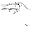
- FIG. 2 shows a cross-section of an embodiment of a fitting member.
- FIG. 1 shows an automobile engine 1 comprising, from top down, a head cover 2, a cylinder head 3, a cylinder block 4, and a crankcase 5, with a chain cover 6 attached in front of the engine 1.
- An intake manifold 8 extending from a surge tank 7 is connected to an intake system (intake passage) of the cylinder head 3.
- a throttle body 9 is connected to the surge tank 7.
- the throttle body 9 includes a throttle valve 10 and is connected through an intake passage 17 to an air cleaner (not shown).
- a PCV valve 11 is attached to the head cover 2.
- a first metallic fitting member 12 is attached to the surge tank 7.
- a chamber S1 in the head cover 2 and the interior of the surge tank 7 are interconnected through a rubber-made PCV hose 13 attached to both the PCV valve 11 and the first fitting member 12.
- the intake passage 17 and the crank chamber S2 in the crankcase 5 are interconnected through a communication hose 18.
- One end of the communication hose 18 is connected to a second metallic fitting member 12' attached to the intake passage 17.
- a blowby gas recirculator is constituted with the PCV valve 11, the first and second fitting members 12, 12', the PCV hose 13, and the communication hose 18.
- Part of the blowby gas finding its way between the piston and the cylinder wall of the engine 1 into the crank chamber S2 of the crankcase 5 is introduced as shown with solid-line arrows in FIG. 1 through the communication hose 18 into the intake passage 17, drawn to the air cleaner (not shown) and returned back to the fresh air flowing through the intake passage 17.
- FIG. 2 shows a surge tank 7 made of an aluminium alloy to which is attached the first fitting member 12 by press-fitting.
- One end of the PCV hose 13 is fit over the first fitting member 12.
- the outer surface of the PCV hose 13 is covered with a pipe-shaped heat insulation material 14.
- the first fitting member 12 in a double tube (pipe) structure comprises an inner tube (pipe) 12A and an outer tube (pipe) 12B.
- the inner tube (pipe) 12A is made of aluminium to be smaller in both wall thickness and heat capacity than the outer tube (pipe) 12B while the outer tube (pipe) 12B is made of iron to be greater in both wall thickness and heat capacity than the inner tube (pipe) 12A.
- Ring-shaped, rubber-made support members 14, 15 are glued by vulcanization to axially spaced end parts of the outside cylindrical surface of the inner pipe 12A to form an air space S between the inner pipe 12A and the outer pipe 12B to serve as a heat insulator.
- a rubber-made cap member 16 is glued by vulcanization to one end of the outside cylindrical surface of the inner pipe 12A.
- the outer pipe 12B is first press-fit into the surge tank 7, and then the inner pipe 12A is fit from one end side (hose attaching side) into the outer pipe 12B.
- the first fitting member 12 of the double pipe structure comprising the inner and outer pipes 12A and 12B is press-fit into the surge tank 7.
- the air space S formed between the inner and outer pipes 12A and 12B of the first fitting member 12 serves as a heat insulator. Therefore, even if the engine 1 is operated at very low temperatures, the blowby gas flowing through the inner pipe 12A of the first fitting member 12 is effectively thermally isolated from very cold external air and the surge tank 7, so that the temperature within the inner pipe 12A is kept above the freezing point and the water content in the blowby gas flowing through the inner pipe 12A is prevented from freezing.
- the first fitting member 12 is prevented from being obstructed by the freezing of the water content with the simple structure, the blowby gas recirculator is assured of stabilized functioning and absence of troubles such as increased internal pressure of the crank chamber S2 due to the obstruction of the first fitting member 12.
- the inner pipe 12A of the first fitting member 12 is made of aluminium to be smaller in both wall thickness and heat capacity than the outer pipe 12A. Therefore, the temperature of the inner pipe 12A is raised by the blowby gas of temperatures generally above the freezing point, the water content is less likely to freeze onto the inner pipe 12A, and so the first fitting member 12 is more effectively prevented from being obstructed with frozen water content.
- FIGs. 3 to 5 show the fitting structure in cross-sections.
- a metallic fitting member 22 shown in FIG. 3(b) is constituted by fitting together an inner pipe 22A and an outer pipe 22B shown in FIG. 3(a).
- One end of the inner pipe 22A has a bell-mouthed portion 22a.
- Sealing members 19, 20 made of an elastic material such as rubber are secured to outside surface at axially opposite ends of the inner pipe 22A.
- a gas-tight chamber S' is defined with the sealing members 19, 20 between the inner and outer pipes 22A, 22B to constitute the fitting member 22.
- the bell-mouthed portion 22a formed at one end of the inner pipe 22A prevents the inner pipe 22A from coming off.
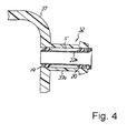
- a fitting member 32 shown in FIG. 4 is constituted by fitting the metallic inner pipe 22A shown in FIG. 3(a) into an outer cylinder 37a formed integrally with a plastic-made surge tank 37.
- a gas-tight chamber S' is also defined with the sealing members 19, 20 between the inner pipe 22A and the outer cylinder 37a.
- a fitting member 42 shown in FIG. 5 is constituted by placing a heat insulation member 43 made of highly heat-insulating material such as expanded urethane rubber between an inner pipe 42A and an outer pipe 42B.
- the fitting member for attaching the one end of the PCV hose of the blowby gas recirculator for returning the blowby gas leaking into the crank chamber of an engine through the PCV hose back to the intake passage is constituted in the double pipe structure with the inner pipe and the outer pipe, an effect is provided that the passage in the fitting member is prevented from being obstructed by the freezing of water content in the blowby gas with a simple structure.
- the embodiments described above refer to a union for attaching to a surge tank 7 one end of a PCV hose 13 of a blowby gas recirculator for returning the blowby gas leaking out to the crank chamber of an engine back to a surge tank 7 (intake passage) through the PCV hose 13 which is constituted in a double pipe structure comprising an inner pipe and an outer pipe.
- An air space S defined between the inner and outer pipes and of the fitting member serves as a heat insulator effectively isolating thermally the blowby gas flowing through the inner pipe against very cold external air and the surge tank 7.
- the embodiments described above particularly disclose a fitting member of a blowby gas recirculator of an engine, wherein blowby gas leaking into the crankcase of the engine is returned through a PCV hose to an intake passage with one end of the PCV hose connected through the fitting member to the intake passage, and wherein the fitting member is made in a double pipe structure with an inner pipe and an outer pipe.
- the inner pipe and the outer pipe are made of different materials.
- the inner pipe is made of a material smaller in both wall thickness and heat capacity than the outer pipe.
- a gas-tight chamber is formed between the inner and outer pipes using sealing members.
- a fitting member 12,12' in particular for a crankcase ventilation system of an internal combustion engine, having a double wall construction comprised of an inner tube 12A received in an outer tube 12B, wherein an outer wall of the inner tube 12A is circumferentially spaced from an inner wall of the outer tube 12B for heat insulation between the inner and the outer tubes 12A,12B.
- the inner tube 12A and the outer tube 12B are made of different, in particular metallic materials.
- the inner tube 12A is made of a material which is smaller in both wall thickness and heat capacity than the outer pipe 12B, in particular that the inner tube 12A is made of aluminium and the outer pipe 12B is made of iron.
- the fitting member further comprises a heat insulating means 43 arranged between the inner tube 42A and the outer tube 42B, wherein the inner tube 42A and the outer tube 42B are held in spaced relationship by means of the heat insulating means 43.
- the heat insulating means 43 is made of highly heat-insulating material, in particular expanded urethane rubber, and extends to positions contiguous to the end sections of one of the inner or the outer tubes 42A,42B or to the end sections of both of the inner and the outer tubes 42A,42B.
- the fitting member further comprises a pair of axially spaced and ring-shaped support members 14,15 arranged to form an insulating air gap S or at least two sealing members 19,20 arranged to form a gas-tight chamber S' between the inner tube 12A,22A and the outer tube 12B,22B and to hold same in a spaced relationship to each other.
- the support members 14,15 or the sealing members 19,20 are positioned contiguous to the respective end sections of one of the inner or the outer tubes 12A,22A,12B,22B or to the respective end sections of both of the inner and the outer tubes 12A,22A,12B,22B.
- the description still further provides an internal combustion engine having a gas re-circulation structure for re-circulation of blow-by gas leaking into a crankcase of the engine to an intake passage of the engine, wherein the gas re-circulation structure comprises at least one fitting member 12,12',22,32,42 having a double wall structure which is comprised of an inner tube 12A received in an outer tube 12B, wherein the outer wall of said inner tube 12 is circumferentially spaced from the inner wall of said outer tube 12' for heat insulation of the blow-by gas being re-circulated to the intake passage 17.
- the inner tube 12A and the outer tube 12B of the fitting member 12,12' are made of different, in particular metallic materials.
- the inner tube 12A is made of a material which is smaller in both wall thickness and heat capacity than the outer pipe 12B, in particular that the inner tube 12A is made of aluminium and the outer pipe 12B is made of iron.
- the internal combustion engine further comprises a heat insulating means 43 arranged between the inner tube 42A and the outer tube 42B of the fitting member 42, wherein the inner tube 42A and the outer tube 42B are held in spaced relationship by means of the heat insulating means 43.
- the insulator means 43 is made of highly heat-insulating material, in particular expanded urethane rubber, and extends to positions contiguous to the end sections of one of the inner or the outer tubes 42A,42B or to the end sections of both of the inner and the outer tubes 42A,42B.
- the internal combustion engine further comprises a pair of axially spaced and ring-shaped support members 14,15 arranged to form an insulating air gap S or at least two sealing members 19,20 arranged to form a gas-tight chamber S' between the inner tube 12A,22A and the outer tube 12B,22B of the fitting member 12,22 and to hold same in a spaced relationship to each other.
- the support members 14,15 or the sealing members 19,20 are positioned contiguous to the respective end sections of one of the inner or the outer tubes 12A,22A,12B,22B or to the respective end sections of both of the inner and the outer tubes 12A,22A,12B,22B.
- the gas re-circulation structure comprises a positive crankcase ventilation hose 13 for re-circulation of blow-by gas leaking into a crankcase of the engine from a head cover 2 to the intake passage 17 of the engine 1, wherein a first fitting member 12 is adapted to connect one end of the positive crankcase ventilation hose 13 to a surge tank 7 of the intake passage 17 of the engine 1.
- the outer tube 12B is press-fitted into the surge tank 7 or the outer tube 37a is formed integrally with the surge tank 37.
- the gas re-circulation structure comprises a communication hose 18 adapted to connect the crankcase 5 with the intake passage 17 of the engine 1, wherein a second fitting member 12' is adapted to connect the communication hose 13 to the intake passage 17.
Landscapes
- Engineering & Computer Science (AREA)
- Mechanical Engineering (AREA)
- General Engineering & Computer Science (AREA)
- Lubrication Details And Ventilation Of Internal Combustion Engines (AREA)
Abstract
Description
- The present invention relates to an internal combustion engine having a gas re-circulation structure.
- In engines for automobiles, etc. the so-called blow-by gas containing a large amount of hydrocarbon (HC) gas leaks through the gap between the piston and the cylinder wall into the crankcase.
- In order to reduce the emission of unwanted hydrocarbons and other combustible material to the atmosphere from internal combustion engines, it has been the practice to ventilate the crankcase of the engine by these blow-by gases passing across the piston rings and into the crankcase chamber.
- To return the blow-by gas back to the intake passage utilizing the intake vacuum, a recirculator is provided, in that these blow-by gases are collected and returned by a crankcase ventilating system that normally utilizes a positive crankcase ventilating (PCV) valve to the induction system of the engine. Thus, these gases are returned to the combustion chamber and further combustion of the undesirable constituents occurs.
- A specific example of such a blow-by gas recirculator is shown in FIG. 6. The blow-by gas leaking through the gap between the piston and the cylinder wall of an engine into the crankcase (not shown) is introduced into a chamber S1 defined with a
baffle plate 120 in ahead cover 102, through a PCV valve 111 and aPCV hose 113 into asurge tank 107, and back to the intake air. - One end of the
PCV hose 113 interconnecting thehead cover 102 and thesurge tank 107 is attached to the PCV valve 111 attached to thehead cover 102. The other end of thePCV hose 113 is attached by being screwed over ametallic union 112 attached to thesurge tank 107. - A problem with this type of positive crankcase system is that when the gases are returned to the induction system and under low ambient temperatures, not only is the induction system but the entire engine at a relatively low temperature, particularly when it is initially started. Thus, when an engine provided with the above-described blow-by gas recirculator is operated at very low temperatures, the
surge tank 107 is cooled with external air and therefore the internal temperature of theunion 112 lowers below the freezing point. As a result, water content in the blow-by gas passing through theunion 112 freezes and obstructs the passage in theunion 112 as shown in the drawing. Therefore, the blow-by gas cannot be returned to the intake air, and various troubles occur due to increased pressure within the crankcase. - Because of the afore-noted problems in connection with condensation and freezing, an insulating sleeve (pipe-shaped heat insulator) 114 frequently is employed encircling the
PCV hose 113 in the area between themetallic union 112 and the PCV valve 111. In spite of this insulation, water vapor in the blow-by gases, which flow in the direction of the arrow shown in this figure, can condense particularly in the area where theunion 112 joins thesurge tank 107. Thus, ice particles indicated at 119 can form in this area and either restrict or in extreme cases totally cut off the re-circulating air flow. - Moreover, measures taken to cover the
union 112 with an insulation material or increasing the diameter of the union are insufficient for solving the problems. While measures of forcibly heating the freezing area with an electric heater or hot water may be considered, such measures are disadvantageous in terms of layout and cost. - It is an objective of the present invention to provide an improved internal combustion engine having a gas re-circulation structure with a simple and effective heat insulating arrangement for connecting the crankcase ventilating tube to the induction system of the engine that will provide adequate insulation to preclude the likelihood of freezing even under extremely low ambient temperatures.
- This objective is solved by an internal combustion engine having a gas-recirculation structure with the features of claim 1.
- Preferably, there is provided an internal combustion engine having a gas re-circulation structure for re-circulation of blow-by gas leaking into a crankcase of the engine to an intake passage of the engine, wherein the gas re-circulation structure comprises at least one fitting member having a double wall structure which is comprised of an inner tube received in an outer tube, wherein the outer wall of said inner tube is circumferentially spaced from the inner wall of said outer tube for heat insulation of the blow-by gas being re-circulated to the intake passage.
- Since, very good insulation is provided, the likelihood that water condensation in the path can freeze and restrict the ventilating flow is avoided.
- According to a preferred embodiment, the gas re-circulation structure comprises a positive crankcase ventilation hose for re-circulation of blow-by gas leaking into a crankcase of the engine from a head cover to the intake passage of the engine, wherein a first fitting member is adapted to connect one end of the positive crankcase ventilation hose to a surge tank of the intake passage of the engine.
- Within this embodiment, it is beneficial if the outer tube is press-fitted into the surge tank or the outer tube is formed integrally with the surge tank.
- According to a further preferred embodiment, the gas re-circulation structure comprises a communication hose adapted to connect the crankcase with the intake passage of the engine, wherein a second fitting member is adapted to connect the communication hose to the intake passage.
- Further preferred embodiments of the internal combustion engine having a gas re-circulation structure are laid down in the further dependent claims.
- It is further beneficial to provide an improved fitting member, in particular for a crankcase ventilation system of an internal combustion engine, preventing the passage from being obstructed by freezing of water content in the blow-by gas and having a simple design.
- It is still further beneficial if there is provided a fitting member, in particular for a crankcase ventilation system of an internal combustion engine, having a double wall construction comprised of an inner tube received in an outer tube, wherein an outer wall of the inner tube is circumferentially spaced from an inner wall of the outer tube for heat insulation between the inner and the outer tubes.
- Since the fitting member is made in a double wall structure with the inner and outer tube, the air space formed between both tubes serves as a heat insulator and effectively isolates the blow-by gas flowing through the inner tube against the external air and the intake passage of very low temperatures. As a result, the temperature within the inner tube is held above the freezing point, and water content in the blow-by gas flowing through the inner tube is prevented from freezing. Therefore, the fitting member is prevented from being obstructed by icing of the water content, and problems due to increased pressure within the crankcase, etc. are effectively prevented.
- According to a preferred embodiment of the fitting member, the inner tube and the outer tube are made of different, in particular metallic materials.
- It is also preferably if the inner tube is made of a material which is smaller in both wall thickness and heat capacity than the outer pipe, in particular that the inner tube is made of aluminium and the outer pipe is made of iron.
- Therefore, the temperature of the inner tube pipe is raised by the blow-by gas of temperatures generally above the freezing point, the water content is less likely to freeze onto the inner tube, and so the fitting member is more effectively prevented from being stopped up with frozen water content.
- According to a further preferred embodiment, the fitting member comprises a heat insulating means arranged between the inner tube and the outer tube, wherein the inner tube and the outer tube are held in spaced relationship by means of the heat insulating means.
- Within this embodiment, it is further preferable if the heat insulating means is made of highly heat-insulating material, in particular expanded urethane rubber, and extends to positions contiguous to the end sections of one of the inner or the outer tubes or to the end sections of both of the inner and the outer tubes.
- According to yet another preferred embodiment, the fitting member comprises a pair of axially spaced and ring-shaped support members arranged to form an insulating air gap or at least two sealing members arranged to form a gas-tight chamber between the inner tube and the outer tube and to hold same in a spaced relationship to each other.
- Within this embodiment, it is beneficial if the support members or the sealing members are positioned contiguous to the respective end sections of one of the inner or the outer tubes or to the respective end sections of both of the inner and the outer tubes.
- Particularly, according to the two embodiments described directly above, freezing of water content in the blow-by gas and resultant blockage of the passage are prevented by means of a simple structure.
- In the following, the present invention is explained in greater detail with respect to several embodiments thereof in conjunction with the accompanying drawings, wherein:
- FIG. 1
- is a conceptual drawing of the constitution of a gas re-circulation structure of an internal combustion engine;
- FIG. 2
- shows a cross-section of an embodiment of a fitting member;
- FIG. 3
- shows a further embodiment of the fitting member in cross-section;
- FIG. 4
- shows a surge tank in partial cross-section showing another embodiment of the fitting member;
- FIG. 5
- shows still another embodiment of a fitting member in cross-section; and
- FIG. 6
- shows a conventional fitting member in cross-section.
- FIG. 1 is a conceptual drawing of the constitution of a gas re-circulation structure (blowby gas recirculator) of an internal combustion engine. FIG. 2 shows a cross-section of an embodiment of a fitting member.
- FIG. 1 shows an automobile engine 1 comprising, from top down, a
head cover 2, acylinder head 3, a cylinder block 4, and acrankcase 5, with a chain cover 6 attached in front of the engine 1. - An
intake manifold 8 extending from asurge tank 7 is connected to an intake system (intake passage) of thecylinder head 3. Athrottle body 9 is connected to thesurge tank 7. Thethrottle body 9 includes athrottle valve 10 and is connected through anintake passage 17 to an air cleaner (not shown). - A PCV valve 11 is attached to the
head cover 2. A firstmetallic fitting member 12 is attached to thesurge tank 7. A chamber S1 in thehead cover 2 and the interior of thesurge tank 7 are interconnected through a rubber-madePCV hose 13 attached to both the PCV valve 11 and thefirst fitting member 12. - The
intake passage 17 and the crank chamber S2 in thecrankcase 5 are interconnected through acommunication hose 18. One end of thecommunication hose 18 is connected to a second metallic fitting member 12' attached to theintake passage 17. - A blowby gas recirculator is constituted with the PCV valve 11, the first and
second fitting members 12, 12', thePCV hose 13, and thecommunication hose 18. Part of the blowby gas finding its way between the piston and the cylinder wall of the engine 1 into the crank chamber S2 of thecrankcase 5 is introduced as shown with solid-line arrows in FIG. 1 through thecommunication hose 18 into theintake passage 17, drawn to the air cleaner (not shown) and returned back to the fresh air flowing through theintake passage 17. - Remaining part of the blowby gas leaking to the crank chamber S2 is led from the crank chamber S2 through the interior of the chain cover 6 to the chamber S1 in the
head cover 2, and further through thecommunication hose 18 to theintake passage 17. The blowby gas introduced into the chamber S1 in thehead cover 2 is drawn from the chamber S1 in thehead cover 2 by the intake vacuum within thesurge tank 7 and introduced into thesurge tank 7 through the PCV valve 11 and thePCV hose 13, and returned to the fresh air in theintake passage 17 introduced through the air cleaner (not shown) and thethrottle body 9 as shown with broken line arrows in FIG. 1 and, together with the first-mentioned part of blowby gas introduced into the fresh air in theintake passage 17, is supplied to the engine 1 through theintake manifold 8 and consumed for combustion. - Next, detailed constitution of the first
fitting member 12 is described in reference to FIG. 2. Since the second fitting member 12' is similarly constituted, explanation thereof is omitted. - FIG. 2 shows a
surge tank 7 made of an aluminium alloy to which is attached the firstfitting member 12 by press-fitting. One end of thePCV hose 13 is fit over the firstfitting member 12. The outer surface of thePCV hose 13 is covered with a pipe-shapedheat insulation material 14. - As shown, the first
fitting member 12 in a double tube (pipe) structure comprises an inner tube (pipe) 12A and an outer tube (pipe) 12B. The inner tube (pipe) 12A is made of aluminium to be smaller in both wall thickness and heat capacity than the outer tube (pipe) 12B while the outer tube (pipe) 12B is made of iron to be greater in both wall thickness and heat capacity than the inner tube (pipe) 12A. - Ring-shaped, rubber-made
support members inner pipe 12A to form an air space S between theinner pipe 12A and theouter pipe 12B to serve as a heat insulator. - A rubber-made
cap member 16 is glued by vulcanization to one end of the outside cylindrical surface of theinner pipe 12A. To assemble the firstfitting member 12, theouter pipe 12B is first press-fit into thesurge tank 7, and then theinner pipe 12A is fit from one end side (hose attaching side) into theouter pipe 12B. - As described above, the first
fitting member 12 of the double pipe structure comprising the inner andouter pipes surge tank 7. The air space S formed between the inner andouter pipes fitting member 12 serves as a heat insulator. Therefore, even if the engine 1 is operated at very low temperatures, the blowby gas flowing through theinner pipe 12A of the firstfitting member 12 is effectively thermally isolated from very cold external air and thesurge tank 7, so that the temperature within theinner pipe 12A is kept above the freezing point and the water content in the blowby gas flowing through theinner pipe 12A is prevented from freezing. As a result, the firstfitting member 12 is prevented from being obstructed by the freezing of the water content with the simple structure, the blowby gas recirculator is assured of stabilized functioning and absence of troubles such as increased internal pressure of the crank chamber S2 due to the obstruction of the firstfitting member 12. - With the embodiment, the
inner pipe 12A of the firstfitting member 12 is made of aluminium to be smaller in both wall thickness and heat capacity than theouter pipe 12A. Therefore, the temperature of theinner pipe 12A is raised by the blowby gas of temperatures generally above the freezing point, the water content is less likely to freeze onto theinner pipe 12A, and so the firstfitting member 12 is more effectively prevented from being obstructed with frozen water content. - Next, another structure of the first fitting member as another embodiment is described in reference to FIGs. 3 to 5 which show the fitting structure in cross-sections.
- A metallic fitting
member 22 shown in FIG. 3(b) is constituted by fitting together aninner pipe 22A and anouter pipe 22B shown in FIG. 3(a). One end of theinner pipe 22A has a bell-mouthed portion 22a.Sealing members inner pipe 22A. A gas-tight chamber S' is defined with the sealingmembers outer pipes fitting member 22. The bell-mouthed portion 22a formed at one end of theinner pipe 22A prevents theinner pipe 22A from coming off. - A fitting member 32 shown in FIG. 4 is constituted by fitting the metallic
inner pipe 22A shown in FIG. 3(a) into an outer cylinder 37a formed integrally with a plastic-madesurge tank 37. A gas-tight chamber S' is also defined with the sealingmembers inner pipe 22A and the outer cylinder 37a. - A
fitting member 42 shown in FIG. 5 is constituted by placing aheat insulation member 43 made of highly heat-insulating material such as expanded urethane rubber between aninner pipe 42A and anouter pipe 42B. - As described above, owing to the heat insulating effect of the gas-tight chamber (air space) S' defined with the
inner pipe 22A,outer pipes 22B, 37a, and sealingmembers fitting members 22 and 32 shown in FIGs. 3 and 4, and owing to the heat insulating effect of theheat insulation member 43 placed between the inner andouter pipes fitting member 42 shown in FIG. 5, passage obstruction due to icing of water content in the blowby gas is prevented with the simple structures. - As is clear from the above description, since the fitting member for attaching the one end of the PCV hose of the blowby gas recirculator for returning the blowby gas leaking into the crank chamber of an engine through the PCV hose back to the intake passage is constituted in the double pipe structure with the inner pipe and the outer pipe, an effect is provided that the passage in the fitting member is prevented from being obstructed by the freezing of water content in the blowby gas with a simple structure.
- The embodiments described above refer to a union for attaching to a
surge tank 7 one end of aPCV hose 13 of a blowby gas recirculator for returning the blowby gas leaking out to the crank chamber of an engine back to a surge tank 7 (intake passage) through thePCV hose 13 which is constituted in a double pipe structure comprising an inner pipe and an outer pipe. - An air space S defined between the inner and outer pipes and of the fitting member serves as a heat insulator effectively isolating thermally the blowby gas flowing through the inner pipe against very cold external air and the
surge tank 7. As a result, the temperature in the inner pipe is kept above the freezing point, the water content in the blowby gas flowing through the inner pipe is prevented from freezing, and the fitting member is protected against obstruction due to freezing of the water content by means of a simple structure. - The embodiments described above particularly disclose a fitting member of a blowby gas recirculator of an engine, wherein blowby gas leaking into the crankcase of the engine is returned through a PCV hose to an intake passage with one end of the PCV hose connected through the fitting member to the intake passage, and wherein the fitting member is made in a double pipe structure with an inner pipe and an outer pipe.
- It is beneficial if the inner pipe and the outer pipe are made of different materials.
- It is also preferable if the inner pipe is made of a material smaller in both wall thickness and heat capacity than the outer pipe.
- It is further beneficial if a heat insulation member is placed between the inner and outer pipes.
- It is further preferable if a gas-tight chamber is formed between the inner and outer pipes using sealing members.
- The description above discloses (amongst others) an embodiment of a
fitting member 12,12', in particular for a crankcase ventilation system of an internal combustion engine, having a double wall construction comprised of aninner tube 12A received in anouter tube 12B, wherein an outer wall of theinner tube 12A is circumferentially spaced from an inner wall of theouter tube 12B for heat insulation between the inner and theouter tubes - Preferably, the
inner tube 12A and theouter tube 12B are made of different, in particular metallic materials. - Further, preferably the
inner tube 12A is made of a material which is smaller in both wall thickness and heat capacity than theouter pipe 12B, in particular that theinner tube 12A is made of aluminium and theouter pipe 12B is made of iron. - Further, preferably the fitting member further comprises a
heat insulating means 43 arranged between theinner tube 42A and theouter tube 42B, wherein theinner tube 42A and theouter tube 42B are held in spaced relationship by means of theheat insulating means 43. - Further, preferably the
heat insulating means 43 is made of highly heat-insulating material, in particular expanded urethane rubber, and extends to positions contiguous to the end sections of one of the inner or theouter tubes outer tubes - Further, preferably the fitting member further comprises a pair of axially spaced and ring-shaped
support members members inner tube outer tube - Further, preferably the
support members members outer tubes outer tubes - The description still further provides an internal combustion engine having a gas re-circulation structure for re-circulation of blow-by gas leaking into a crankcase of the engine to an intake passage of the engine, wherein the gas re-circulation structure comprises at least one fitting
member inner tube 12A received in anouter tube 12B, wherein the outer wall of saidinner tube 12 is circumferentially spaced from the inner wall of said outer tube 12' for heat insulation of the blow-by gas being re-circulated to theintake passage 17. - Preferably, the
inner tube 12A and theouter tube 12B of thefitting member 12,12' are made of different, in particular metallic materials. - Further, preferably the
inner tube 12A is made of a material which is smaller in both wall thickness and heat capacity than theouter pipe 12B, in particular that theinner tube 12A is made of aluminium and theouter pipe 12B is made of iron. - Still further, preferably the internal combustion engine further comprises a
heat insulating means 43 arranged between theinner tube 42A and theouter tube 42B of thefitting member 42, wherein theinner tube 42A and theouter tube 42B are held in spaced relationship by means of theheat insulating means 43. - Preferably, the insulator means 43 is made of highly heat-insulating material, in particular expanded urethane rubber, and extends to positions contiguous to the end sections of one of the inner or the
outer tubes outer tubes - Further, preferably the internal combustion engine further comprises a pair of axially spaced and ring-shaped
support members members inner tube outer tube fitting member - Further, preferably the
support members members outer tubes outer tubes - Further, preferably the gas re-circulation structure comprises a positive
crankcase ventilation hose 13 for re-circulation of blow-by gas leaking into a crankcase of the engine from ahead cover 2 to theintake passage 17 of the engine 1, wherein a firstfitting member 12 is adapted to connect one end of the positivecrankcase ventilation hose 13 to asurge tank 7 of theintake passage 17 of the engine 1. - Further, preferably the
outer tube 12B is press-fitted into thesurge tank 7 or the outer tube 37a is formed integrally with thesurge tank 37. - Further, preferably the gas re-circulation structure comprises a
communication hose 18 adapted to connect thecrankcase 5 with theintake passage 17 of the engine 1, wherein a second fitting member 12' is adapted to connect thecommunication hose 13 to theintake passage 17.
Claims (4)
- Internal combustion engine having a gas re-circulation structure for re-circulation of blow-by gas leaking into a crankcase of the engine to an intake passage of the engine, wherein the gas re-circulation structure comprises at least one fitting member having a double wall structure constituted by fitting a metallic inner pipe (22A) into an outer cylinder (37a) formed integrally with a plastic-made surge tank (37) such that an outer wall of the inner pipe (22A) is circumferentially spaced from an inner wall of the outer cylinder (37a) for heat insulation of the blow-by gas being re-circulated to the intake passage (17).
- Internal combustion engine according to claim 1, wherein one end of the inner pipe (22A) has a bell-mouthed portion (22a).
- Internal combustion engine according to claim 1 or 2, wherein sealing members (19,20) made of an elastic material, in particular rubber, are secured to an outside surface of the inner pipe (22A) at axially opposite ends thereof.
- Internal combustion engine according to claim 3, wherein a gas-tight chamber (S') is defined with the sealing members (19,20) between the inner pipe (22A) and the outer cylinder (37a) to constitute the fitting member (32).
Applications Claiming Priority (2)
| Application Number | Priority Date | Filing Date | Title |
|---|---|---|---|
| JP2000352232A JP2002155720A (en) | 2000-11-20 | 2000-11-20 | Union structure of blow-by gas reduction unit |
| EP01127596A EP1207279B1 (en) | 2000-11-20 | 2001-11-19 | Internal combustion engine and fitting member |
Related Parent Applications (2)
| Application Number | Title | Priority Date | Filing Date |
|---|---|---|---|
| EP01127596A Division EP1207279B1 (en) | 2000-11-20 | 2001-11-19 | Internal combustion engine and fitting member |
| EP01127596.3 Division | 2001-11-19 |
Publications (3)
| Publication Number | Publication Date |
|---|---|
| EP1715149A2 true EP1715149A2 (en) | 2006-10-25 |
| EP1715149A3 EP1715149A3 (en) | 2010-07-21 |
| EP1715149B1 EP1715149B1 (en) | 2012-02-22 |
Family
ID=18825163
Family Applications (2)
| Application Number | Title | Priority Date | Filing Date |
|---|---|---|---|
| EP06015609A Expired - Lifetime EP1715149B1 (en) | 2000-11-20 | 2001-11-19 | Internal combustion engine |
| EP01127596A Expired - Lifetime EP1207279B1 (en) | 2000-11-20 | 2001-11-19 | Internal combustion engine and fitting member |
Family Applications After (1)
| Application Number | Title | Priority Date | Filing Date |
|---|---|---|---|
| EP01127596A Expired - Lifetime EP1207279B1 (en) | 2000-11-20 | 2001-11-19 | Internal combustion engine and fitting member |
Country Status (4)
| Country | Link |
|---|---|
| US (1) | US6601572B2 (en) |
| EP (2) | EP1715149B1 (en) |
| JP (1) | JP2002155720A (en) |
| DE (1) | DE60126042T2 (en) |
Families Citing this family (31)
| Publication number | Priority date | Publication date | Assignee | Title |
|---|---|---|---|---|
| FR2826691B1 (en) * | 2001-07-02 | 2003-09-26 | Solvay | CIRCUIT FOR RESPIRATING THE CRANKCASE GASES OF AN INTERNAL COMBUSTION ENGINE |
| DE10142979C1 (en) * | 2001-09-01 | 2003-05-28 | Porsche Ag | Exhaust manifold of an exhaust system for an internal combustion engine |
| US6782878B2 (en) * | 2003-01-27 | 2004-08-31 | General Motors Corporation | PCV assembly and fitting |
| DE10339622B4 (en) * | 2003-08-28 | 2006-01-26 | Mündener Gummiwerk Gmbh | Device for returning gases or gases and liquids from a crankcase or other cavity of an internal combustion engine into an intake line of the internal combustion engine |
| JP4020059B2 (en) * | 2003-10-10 | 2007-12-12 | 日産自動車株式会社 | Intake device for internal combustion engine |
| SE525410C2 (en) * | 2004-04-05 | 2005-02-15 | Scania Cv Abp | Crankcase ventilation system for internal combustion engine, uses heat from oil sump to prevent ventilation outlet from freezing |
| DE102004031808A1 (en) * | 2004-07-01 | 2006-01-26 | Daimlerchrysler Ag | Crankcase breather with heat shield |
| US7441551B2 (en) | 2005-08-22 | 2008-10-28 | Honda Motor Co., Ltd. | Intake manifold |
| JP4683486B2 (en) * | 2006-02-21 | 2011-05-18 | 本田技研工業株式会社 | Engine with breather device |
| FR2910554B1 (en) * | 2006-12-22 | 2009-01-23 | Renault Sas | INTERNAL COMBUSTION ENGINE HEAD |
| JP4321606B2 (en) * | 2007-02-28 | 2009-08-26 | トヨタ自動車株式会社 | Blow-by gas reduction device, cylinder head used in the blow-by gas reduction device, and internal combustion engine including the blow-by gas reduction device |
| US8210135B2 (en) * | 2008-02-08 | 2012-07-03 | Caterpillar Inc. | Crankcase ventilation system |
| CN101749082B (en) * | 2009-12-21 | 2012-06-27 | 奇瑞汽车股份有限公司 | Ventilating passage for crankcase ventilating system |
| DE102010034153A1 (en) * | 2010-08-11 | 2012-02-16 | Voith Patent Gmbh | Steam energy plant and method for its operation |
| JP5321852B2 (en) | 2011-04-01 | 2013-10-23 | マツダ株式会社 | Engine blow-by gas recirculation system |
| EP2713025B1 (en) * | 2011-05-19 | 2016-09-07 | Toyota Jidosha Kabushiki Kaisha | Air intake structure for internal combustion engine |
| JP5886620B2 (en) * | 2011-12-21 | 2016-03-16 | 株式会社ニフコ | Blow-by gas recirculation passage structure |
| US9074563B2 (en) | 2013-08-07 | 2015-07-07 | Ford Global Technologies, Llc | Engine system having a condensate bypass duct |
| US9316183B2 (en) | 2013-08-15 | 2016-04-19 | Ford Global Technologies, Llc | Air intake duct ice ingestion features |
| JP6404243B2 (en) * | 2014-02-12 | 2018-10-10 | 株式会社ニフコ | Blow-by heater |
| JP6538006B2 (en) * | 2016-06-28 | 2019-07-03 | 株式会社クボタ | Blowby gas return structure |
| DE102016226019B4 (en) * | 2016-12-22 | 2022-12-15 | Mahle International Gmbh | Coupling element of a crankcase ventilation device |
| DE102017002501B4 (en) * | 2017-03-15 | 2020-07-02 | Audi Ag | Internal combustion engine with a ventilation line, motor vehicle and method for monitoring a ventilation line of an internal combustion engine |
| JP6856476B2 (en) * | 2017-08-31 | 2021-04-07 | ダイキン工業株式会社 | How to maintain the drain hose connection adapter, air conditioning system, and drain piping |
| JP7022655B2 (en) * | 2018-06-07 | 2022-02-18 | 株式会社クボタ | Blow-by gas recirculation device |
| JP2020029832A (en) * | 2018-08-24 | 2020-02-27 | 株式会社豊田自動織機 | Suction/exhaust structure of internal combustion engine |
| KR102363934B1 (en) * | 2019-10-17 | 2022-02-17 | 말레동현필터시스템 주식회사 | Nipple assembly |
| US11319845B1 (en) | 2021-04-23 | 2022-05-03 | Caterpillar Inc. | Crankcase ventilation system |
| JP2023128634A (en) * | 2022-03-04 | 2023-09-14 | ダイハツ工業株式会社 | Automotive engine intake manifold |
| CN115773166B (en) * | 2022-11-29 | 2024-04-12 | 重庆长安汽车股份有限公司 | Structure and method for preventing crankcase ventilation pipeline from icing |
| CN118934157B (en) * | 2024-08-19 | 2025-10-24 | 潍柴动力股份有限公司 | Method for preventing icing of engine system, vehicle and oil-gas separator outlet pipe |
Citations (1)
| Publication number | Priority date | Publication date | Assignee | Title |
|---|---|---|---|---|
| EP0816666A2 (en) | 1996-07-05 | 1998-01-07 | Elring Klinger GmbH | Exhaust gas recirculation device |
Family Cites Families (10)
| Publication number | Priority date | Publication date | Assignee | Title |
|---|---|---|---|---|
| JPS5819284Y2 (en) | 1977-07-18 | 1983-04-20 | トヨタ自動車株式会社 | Ventilation valve anti-freezing thermal cover |
| DE3932300C2 (en) | 1989-09-28 | 2003-03-06 | Siemens Ag | throttle body |
| DE9102926U1 (en) * | 1991-03-12 | 1991-08-08 | Leistritz AG & Co Abgastechnik, 8510 Fürth | Air gap insulated front pipe |
| US5551409A (en) * | 1995-12-01 | 1996-09-03 | Chrysler Corporation | Oil separator for engine vent system |
| JPH09264129A (en) | 1996-01-25 | 1997-10-07 | Aisin Takaoka Ltd | Exhaust manifold |
| JPH09317569A (en) * | 1996-05-22 | 1997-12-09 | Nippon Soken Inc | Engine gas recirculation system |
| JPH10331621A (en) | 1997-05-30 | 1998-12-15 | Suzuki Motor Corp | Breather passage structure of internal combustion engine |
| JP3282072B2 (en) | 1997-09-26 | 2002-05-13 | 株式会社クボタ | Engine breather device |
| DE19854521C1 (en) * | 1998-11-26 | 2000-06-08 | Muendener Gummiwerk Gmbh | Insulated hose line for transporting gas or liquid, with spacing projections in form of pins, bolts etc. |
| JP2001214995A (en) | 1999-11-24 | 2001-08-10 | Pacific Ind Co Ltd | Union with heater |
-
2000
- 2000-11-20 JP JP2000352232A patent/JP2002155720A/en active Pending
-
2001
- 2001-10-02 US US09/682,649 patent/US6601572B2/en not_active Expired - Lifetime
- 2001-11-19 EP EP06015609A patent/EP1715149B1/en not_active Expired - Lifetime
- 2001-11-19 DE DE60126042T patent/DE60126042T2/en not_active Expired - Fee Related
- 2001-11-19 EP EP01127596A patent/EP1207279B1/en not_active Expired - Lifetime
Patent Citations (1)
| Publication number | Priority date | Publication date | Assignee | Title |
|---|---|---|---|---|
| EP0816666A2 (en) | 1996-07-05 | 1998-01-07 | Elring Klinger GmbH | Exhaust gas recirculation device |
Also Published As
| Publication number | Publication date |
|---|---|
| EP1207279A1 (en) | 2002-05-22 |
| EP1207279B1 (en) | 2007-01-17 |
| DE60126042D1 (en) | 2007-03-08 |
| DE60126042T2 (en) | 2007-05-10 |
| US20020134361A1 (en) | 2002-09-26 |
| US6601572B2 (en) | 2003-08-05 |
| EP1715149A3 (en) | 2010-07-21 |
| JP2002155720A (en) | 2002-05-31 |
| EP1715149B1 (en) | 2012-02-22 |
Similar Documents
| Publication | Publication Date | Title |
|---|---|---|
| EP1715149B1 (en) | Internal combustion engine | |
| US6234154B1 (en) | Integral PCV system | |
| US6412479B1 (en) | Thermal management system for positive crankcase ventilation system | |
| CN203146301U (en) | Reciprocating pump assembly for pumping cryogenic fluid, and system comprising the same | |
| US8020541B2 (en) | Positive crankcase ventilation system | |
| US6390080B1 (en) | Intake manifold with a heated PCV passage | |
| US6782878B2 (en) | PCV assembly and fitting | |
| US20030140908A1 (en) | PCV apparatus | |
| WO2020031894A1 (en) | Blowby gas atmosphere releasing device | |
| JP3904425B2 (en) | Blow-by gas processing device for internal combustion engine | |
| GB2158152A (en) | Heating i.c. engine PCV valves | |
| WO2009108085A1 (en) | Crank case ventilation | |
| JP2006063884A (en) | Engine blow-by gas recirculation system | |
| US6418917B1 (en) | Closed crankcase breather system | |
| US7168421B2 (en) | Crankcase ventilation | |
| JP2511758Y2 (en) | Blow-by gas recirculation system for internal combustion engine | |
| CN113638788B (en) | Anti-blocking air filtering pipeline | |
| US5944000A (en) | Venting arrangement in an intake duct of an internal combustion engine | |
| JP3282072B2 (en) | Engine breather device | |
| JP2016135996A (en) | Freezing preventive structure for blow-by gas pipe, internal combustion engine and freezing preventive method for blow-by gas pipe | |
| JP2510164Y2 (en) | Blow-by passage freeze prevention structure for internal combustion engine | |
| KR20070002939A (en) | Anti-icing nipple of engine ventilation system | |
| JP2539849Y2 (en) | Blow-by gas reduction device | |
| CN110529696A (en) | A kind of connection structure for preventing crankcase ventilation pipeline ice blockage | |
| CN222910096U (en) | Gas-driven respirator device integrated with engine oil heating |
Legal Events
| Date | Code | Title | Description |
|---|---|---|---|
| PUAI | Public reference made under article 153(3) epc to a published international application that has entered the european phase |
Free format text: ORIGINAL CODE: 0009012 |
|
| 17P | Request for examination filed |
Effective date: 20060726 |
|
| AC | Divisional application: reference to earlier application |
Ref document number: 1207279 Country of ref document: EP Kind code of ref document: P |
|
| AK | Designated contracting states |
Kind code of ref document: A2 Designated state(s): DE FR GB IT |
|
| AX | Request for extension of the european patent |
Extension state: AL LT LV MK RO SI |
|
| PUAL | Search report despatched |
Free format text: ORIGINAL CODE: 0009013 |
|
| AK | Designated contracting states |
Kind code of ref document: A3 Designated state(s): DE FR GB IT |
|
| AX | Request for extension of the european patent |
Extension state: AL LT LV MK RO SI |
|
| AKX | Designation fees paid |
Designated state(s): DE FR GB IT |
|
| GRAP | Despatch of communication of intention to grant a patent |
Free format text: ORIGINAL CODE: EPIDOSNIGR1 |
|
| RIC1 | Information provided on ipc code assigned before grant |
Ipc: F01M 13/00 20060101AFI20110704BHEP |
|
| GRAS | Grant fee paid |
Free format text: ORIGINAL CODE: EPIDOSNIGR3 |
|
| GRAA | (expected) grant |
Free format text: ORIGINAL CODE: 0009210 |
|
| RIN1 | Information on inventor provided before grant (corrected) |
Inventor name: OKAMOTO, YASUO |
|
| AC | Divisional application: reference to earlier application |
Ref document number: 1207279 Country of ref document: EP Kind code of ref document: P |
|
| AK | Designated contracting states |
Kind code of ref document: B1 Designated state(s): DE FR GB IT |
|
| REG | Reference to a national code |
Ref country code: GB Ref legal event code: FG4D |
|
| REG | Reference to a national code |
Ref country code: DE Ref legal event code: R096 Ref document number: 60146164 Country of ref document: DE Effective date: 20120419 |
|
| PG25 | Lapsed in a contracting state [announced via postgrant information from national office to epo] |
Ref country code: IT Free format text: LAPSE BECAUSE OF FAILURE TO SUBMIT A TRANSLATION OF THE DESCRIPTION OR TO PAY THE FEE WITHIN THE PRESCRIBED TIME-LIMIT Effective date: 20120222 |
|
| PLBE | No opposition filed within time limit |
Free format text: ORIGINAL CODE: 0009261 |
|
| STAA | Information on the status of an ep patent application or granted ep patent |
Free format text: STATUS: NO OPPOSITION FILED WITHIN TIME LIMIT |
|
| 26N | No opposition filed |
Effective date: 20121123 |
|
| REG | Reference to a national code |
Ref country code: DE Ref legal event code: R097 Ref document number: 60146164 Country of ref document: DE Effective date: 20121123 |
|
| GBPC | Gb: european patent ceased through non-payment of renewal fee |
Effective date: 20121119 |
|
| PG25 | Lapsed in a contracting state [announced via postgrant information from national office to epo] |
Ref country code: GB Free format text: LAPSE BECAUSE OF NON-PAYMENT OF DUE FEES Effective date: 20121119 |
|
| REG | Reference to a national code |
Ref country code: FR Ref legal event code: PLFP Year of fee payment: 15 |
|
| REG | Reference to a national code |
Ref country code: FR Ref legal event code: PLFP Year of fee payment: 16 |
|
| REG | Reference to a national code |
Ref country code: FR Ref legal event code: PLFP Year of fee payment: 17 |
|
| PGFP | Annual fee paid to national office [announced via postgrant information from national office to epo] |
Ref country code: FR Payment date: 20171121 Year of fee payment: 17 Ref country code: DE Payment date: 20171121 Year of fee payment: 17 |
|
| REG | Reference to a national code |
Ref country code: DE Ref legal event code: R119 Ref document number: 60146164 Country of ref document: DE |
|
| PG25 | Lapsed in a contracting state [announced via postgrant information from national office to epo] |
Ref country code: FR Free format text: LAPSE BECAUSE OF NON-PAYMENT OF DUE FEES Effective date: 20181130 Ref country code: DE Free format text: LAPSE BECAUSE OF NON-PAYMENT OF DUE FEES Effective date: 20190601 |