EP1715134A2 - Un système de ventilation renversable pour fenêtres - Google Patents
Un système de ventilation renversable pour fenêtres Download PDFInfo
- Publication number
- EP1715134A2 EP1715134A2 EP06008282A EP06008282A EP1715134A2 EP 1715134 A2 EP1715134 A2 EP 1715134A2 EP 06008282 A EP06008282 A EP 06008282A EP 06008282 A EP06008282 A EP 06008282A EP 1715134 A2 EP1715134 A2 EP 1715134A2
- Authority
- EP
- European Patent Office
- Prior art keywords
- window
- door
- ventilation
- ventilation element
- base plate
- Prior art date
- Legal status (The legal status is an assumption and is not a legal conclusion. Google has not performed a legal analysis and makes no representation as to the accuracy of the status listed.)
- Withdrawn
Links
Images
Classifications
-
- E—FIXED CONSTRUCTIONS
- E06—DOORS, WINDOWS, SHUTTERS, OR ROLLER BLINDS IN GENERAL; LADDERS
- E06B—FIXED OR MOVABLE CLOSURES FOR OPENINGS IN BUILDINGS, VEHICLES, FENCES OR LIKE ENCLOSURES IN GENERAL, e.g. DOORS, WINDOWS, BLINDS, GATES
- E06B7/00—Special arrangements or measures in connection with doors or windows
- E06B7/02—Special arrangements or measures in connection with doors or windows for providing ventilation, e.g. through double windows; Arrangement of ventilation roses
- E06B7/10—Special arrangements or measures in connection with doors or windows for providing ventilation, e.g. through double windows; Arrangement of ventilation roses by special construction of the frame members
Definitions
- the invention is directed to a window or door ventilation system, comprising a trained in the window or door rebate vent whose inputs and outputs are formed by interruptions or perforations in the circumferentially formed between a window or door leaf and a window frame window seal, wherein in the Ventilation path, preferably in the window or Mosfalz arranged first window or door ventilation element with a Ventilventvolumenstromber in the form of a lufttik- and / or ventilating volume flow dependent automatically opening and closing shuttle valve and a second window or door ventilation element in the form of a sealing slide in an interruptions and perforations the circumferential window or door seal occlusive closure position is movable. Furthermore, the invention is directed to a window or a door with a trained in the window or the door window or door ventilation system.
- the minimum ventilation is the air exchange which is necessary so that it does not cause damage to moisture, in particular mold infestation. In order to prevent mold growth, a minimum air change of 0.15 to 0.4 per hour is assumed, ie 15% to 40% of the volume of domestic air should be exchanged per hour. For basic and demand ventilation, an air exchange is required which is set at 0.5 per hour, ie an air exchange of 50% of the air volume.
- the minimum ventilation should be independent of the occupants and, as far as possible, self-regulating, especially if windows remain closed.
- the outer wall diffusers must be designed so that both minimum and basic / demand ventilation can be covered.
- window or door ventilation elements have been created, which are installed in the window or door rebate or which are subsequently attached to the outside of the window or door or which are attached to the window or door frame and a leading through the window rebate air flow path from the inside form outside or from outside to inside and thus allow an exchange of air.
- Many of these systems are designed as retrofittable elements and are designed so that the minimum ventilation can be carried out automatically with them.
- these ventilation elements are usually equipped with a pendulum flap.
- Such a window or door ventilation element which has these disadvantages, is sold, for example, by Gealan under the product name "Gecco3".
- a window or door ventilation element which is arranged in the fold between the sash and the frame, is also from the DE 199 29 133 A1 known.
- This known ventilation element is due to its arrangement in the fold but only suitable to ensure the necessary minimum ventilation.
- a generic window or door ventilation system which comprises a first window or door ventilation element and a second window or door ventilation element, both of which are formed in the ventilation path formed in a window fold, is known from the German utility model DE 201 05 296 U1 known.
- this window or door ventilation system an inside opening is provided, which is associated with both the first and the second window or door ventilation element. This makes it possible to completely close the ventilation path with the help of the second window or door ventilation element or to open in intermediate positions to a full open position, in which case still the regulation of the first window or door ventilation element is effective in the ventilation path.
- this window or door ventilation system it is possible to ensure the necessary minimum ventilation. However, a maximum of one volume flow is possible, which is transmitted when the second window or door ventilation element is fully opened by the first window or door ventilation element.
- the invention is therefore based on the object zaffaffen a solution that allows both the fulfillment of the requirements of a minimum ventilation and the requirements of a basic or demand ventilation, without the need to open the respective window or door leaf for ventilation purposes is necessary.
- this object is achieved in that the first window or door ventilation element for free ventilation according to DIN 1946-6 required air exchange rates per unit time for a user-independent minimum ventilation over navalwand carefullylässe ready and the second window or Door ventilation element which also causes required for a basic and / or demand ventilation volume flow.
- a window-integrated or door-integrated, manually adjustable ventilation system in which as the first window or door ventilation element of the automatically controlling Falzlparticularlyer example, a sold under the term criz-air® or from the DE 199 29 133 A1 known Novafalzlformater ensures the fulfillment of the requirements of a minimum ventilation and as a second window or door ventilation element manually operable Window or door ventilation element, preferably arranged as a sash overflow fan on a side edge of a window or door leaf, which meets the requirements of a basic or demand ventilation, without the need to open the window sash for ventilation purposes is necessary.
- the invention provides that the first window or door ventilation element provides the required for free ventilation according to DIN 1946-6 air exchange rates per unit time for a user-independent minimum ventilation over navalwand carefullylässe and the second window or door ventilation element beyond the addition of a basic and / or Demand ventilation required volume flow causes.
- the invention provides that the first window or door ventilation element is associated with a first input / output of the ventilation path and the second window or door ventilation element is associated with a second input / output.
- first window or door ventilation element is arranged in a leading to the first input / output ventilation path and the second window or door ventilation element in a leading to the second input / output ventilation path, which the invention further provides ,
- a particularly favorable flow and utilization of the ventilation path results according to the invention then, when the first and the second window or door ventilation element are arranged on opposite sides of the window or the door.
- first and second window or door ventilation element For the interaction of the first and second window or door ventilation element has proven to be the most effective and efficient arrangement to use the caring for the minimum ventilation first window or door ventilation element at the top of the window or door and the second window or door ventilation element at the bottom of the window or door to be set.
- the invention therefore further provides that the first window or door ventilation element is arranged at the top of a window or a door, and the second window or door element is arranged at the bottom of the window or the door.
- the invention is characterized by a second window or door ventilation element with an at least partially engaging in the area of the sash overlap between window or door overlap base plate with lateral guide webs and / or lateral boundary surfaces or walls and at least one the ventilation volume flow in the window or Mosfalz influencing Ventilation element, wherein the base plate has on its longitudinal side at least two protruding Begrenzungsstege, which are engageably positioned in the sealing region of the sash gasket between window or door and window or door frame to form the air flow path, so that the window or door ventilation element on the window or door flap or attachable to the adjoining region of window or door frame in a window or door rebate ventilating use position, wherein on the base plate of the sealing slide in the, the air flow sweeping Ventilation flow influenceable manner is arranged adjustable and the window or door ventilation element, in particular the base plate and the sealing slide, at least in the adjoining the wing flap seal region of the width extension of the window or door wing such a width and height extension have / have that
- a ventilation system is provided with a ventilation element, which is to be attached later on each side of a window or door leaf or frame, without thereby obstructing the function of the window, in particular provided tilting or pivoting movements.
- a ventilation element which is to be attached later on each side of a window or door leaf or frame, without thereby obstructing the function of the window, in particular provided tilting or pivoting movements.
- the width and height extent of the ventilation element is so small that without making changes to conventional, existing fittings, the pivoting of the respective edge region of window or door wings, to which the ventilation element is still appropriate.
- the air flow path to the window or door rebate can be opened, closed or adjusted by means of the adjustable sealing slide, so that by means of the ventilation element an air exchange to the exterior wall passage adjacent apartment is made possible, at least in combination with the minimum ventilation ensuring further ventilation element meets the requirements of a basic and / or demand ventilation.
- Ventilation element that can be subsequently attached to a window or a door, and in particular in that only a portion of the window or door flap over seal in the area in which the ventilation element is to be used, for its attachment must be removed, can also be removed back from the window. In this case, the seal must then be replaced piecewise or in sections or on the entire, concerned longitudinal side. Otherwise, the door or the window can then be used again without ventilation element. In particular, no sections in window or door or window or door frame must be incorporated to its attachment.
- a particularly flat and low-profile embodiment of the window or door ventilation element, the rotation and / or tilting movements of the window equipped therewith or the door equipped therewith not hindered, can be achieved when flat, plate-shaped elements are used.
- the invention therefore provides in an embodiment that the sealing slide is formed in particular plate-shaped and is slidably mounted between the base plate and an upper guide plate. This makes it possible to easily realize a flat construction, adjustable ventilation element.
- a particularly expedient guidance of the seal slide on the base plate can be achieved in that the base plate has screw and guide dome, which engage in slot openings of the seal slide.
- the invention furthermore provides that the sealing slide has on its longitudinal edge a sealing nose, preferably made of injection-molded, soft plastic.
- the ventilation element may have on the base plate side boundary surfaces or walls.
- the invention further distinguishes itself in that the lateral boundary walls in the installation or use position or Matblendrahmen facing area bevels, which are dimensioned such that they do not tilt or pivot in the installation or use position of the window or door ventilation element adjacent window or door in its open position or at most in the maximum opening position of the window or Door leaf come into contact with the window or door frame.
- the second window or door ventilation element which is manually operable by means of the sealing slide, interacts with the first window or door ventilation element, which is preferably self-regulating and positioned in particular in the window and door rabbet.
- the invention provides a window or a door, which is characterized in that it comprises a window or door ventilation system according to one of claims 1 to 11.
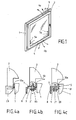
- Fig. 1 shows a perspective view of an outer wall passage in the form of a window.
- the window comprises a frame 1 and a pivotally and tiltably mounted sash 2.
- a ventilation path is formed, which thereby inputs and outputs from outside to inside, that the circulating between sash and frame 1 formed window seal on the outside and on the inside is partially interrupted or perforated.
- the window or door ventilation system comprises a first window or door ventilation element 3, which is arranged in the region of the upper transverse spar of the window frame 1 in the window rebate 30.
- the window or door ventilation system comprises a (second) window or door ventilation element 4, which is arranged on the lower wing flap 25 of the window sash 2, ie on the opposite side of the window to the first window or door ventilation element 3.
- a (second) window or door ventilation element 4 By formed in the outer circumferential seal between the window sash 2 and frame 1 openings flows from the outside, indicated by the arrows 5a and 5b, fresh air in the Brefalz Scheme between frame 1 and sash second one.
- the fresh air passes both to the first window or door ventilation element 3 and flows there, indicated by arrows 6a, as supply air in the apartment interior and to the (second) window or door ventilation element 4 and flows there, indicated by arrows 6b, as supply air in the adjoining apartment interior.
- the ventilation path from the outside 5a, 5b shown inwardly 6a, 6b the air flow can also be reversed from the inside out.
- the additional, further, second window or door ventilation element 4 is provided, which was developed for this purpose.
- This particular on the sash overlap 25 to be positioned window or door ventilation system 4 requires no structural changes, in particular no milled on the sash 2.
- the sash gasket 16 is removed and by the with its boundary webs 10 a to Replaced 10e engaging in this area window or door ventilation element 4, which is mounted on the window sash 25.
- the closed position of the sealing slide 8 then takes over in the region of the recessed wing flap seal 16 with its sealing lug 19 plan on the frame 1 and the frame surface 27 fitting sealing slide 8, the sealing function of the wing flap seal 16.
- the sash 2 can be moved at any time, because due to the geometric dimensions and design of the second window or door ventilation element 4 whose rotation and tilt function is not hindered by the trained as a sash override second window or door ventilation element 4.
- the self-opening and closing shuttle flap 31 of the first window or door ventilation element 3 makes it possible to fulfill the minimum ventilation conditions specified in DIN 1946-6.
- first window or door ventilation element 3 is arranged at the top in the region of the transverse spar of window frame 1 and sash 2 in the upper window rebate 30 and the second window or door ventilation element 4 is fixed on the opposite side of the sash overlap 25, results in a particularly efficient and effective interaction of the two window or door ventilation elements 3, 4.
- the exhaust air is discharged at the top of the window (6a) and the fresh air supplied to the interior flows down over the wing overrun ventilator or the second window - Or door ventilation element 4 (6b) in the interior.
- the ventilation path from the outside 5a, 5b inwardly 6a, 6b is shown, the air flow can also be reversed from the inside out.
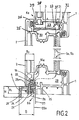
- the window or door ventilation elements in particular the second window or door ventilation element 4 is technically preferably made of plastic by injection molding. But it is also possible to make the base plate 7, the sealing slide 8 and the upper guide plate 9, for example, metal.
- the first window or door ventilation element 3 is arranged, which has a Vietnamesezu- and removal automatically regulating pendulum flap 31.
- This first window or door ventilation elements 3 is known as Regel-air® and, for example, in the DE 199 29 133 A1 described.
- This first window or door ventilation element 3 provides the required for a free ventilation according to DIN 1946-6 air exchange rate per unit time for a user-independent minimum ventilation oversupervisedwand trimlässe.
- the second window or door ventilation element 4 which cooperates with the first window or door ventilation element 3 arranged on the window frame 1, furthermore provides the air exchange quantity required for basic and / or demand ventilation.
- the second window or door ventilation element 4 consists of a base plate 7, a sealing slide 8 and an upper guide plate 9, wherein the sealing slide 8 is arranged between the lower base plate 7 and the upper guide plate 9 ,
- the base plate 7 has at a longitudinal edge projecting and at right angles angled from the base of the base plate 7 extending boundary webs 10a to 10e, in the installation or use position shown in Figs. 2 and 4a to 4c of the second window or door ventilation element 4 between form one or more slit-shaped openings 11a to 11d, which are part of the air flow path 6b.
- the second window or door ventilation element 4 with its boundary webs 10 a and 10 e seamlessly in the interrupted at this point, otherwise encircling wing flap gasket 16, so that by the slit-shaped openings 11a to 11d guided air flow path 6b is laterally sealed.
- screw and guide domes 17a to 17c are formed in the base surface of the base plate 7.
- the screw and guide domes 17a to 17c protrude from the base of the base plate 7 and centrally have an opening for receiving a screw thread of a screw 21, by means of which the window ventilation element 4 is fixed to the window sash 25.
- the sealing slide 8 is slidably guided on the base surface of the base plate 7 with its lateral edge regions between the lateral guide webs 12, 13 guided.
- the screw and guide dome 17a to 17c engage in slot openings 18a to 18c of the sealing slide 8, so that this results in a further guidance of the sealing slide 8 on the base plate 7.
- a sealing edge or sealing lug 19 is arranged; which consists of a molded, soft plastic.
- a handle bar 20 is formed, which extends over the entire length of the sealing slide 8.
- this handle bar 20 of the sliding on the base plate 7 mounted sealing slide 8 is manually detectable and movable in its various opening positions. In this case, there is a maximum position of the sealing slide in the Closure position, as shown in Fig. 4c, and the other in the maximum opening position in which the sealing lug 19 behind the slit-shaped openings 11a to 11d delimiting the longitudinal side edge of the base plate 7 is retracted.
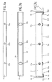
- the lateral guide webs 12, 13 are formed relatively flat and have approximately a thickness which corresponds approximately to the thickness of the base plate 7, the thickness of the sealing slide 8 and the thickness of the upper guide plate 9, which are each 1 mm to 5 mm, have the lateral boundary walls 23, 24 a significantly greater extent, which is flush with the height and extent of the handle bar 20.
- the sealing slide 8 is arranged in the direction transverse to and perpendicular to the flow direction of the formed in the sealing region of the wing flap seal flow path 6b, wherein it is further arranged displaceably in this direction on the base plate 7.
- the second window or door ventilation element 4 has such a width extension B and such a height extent H that in the use position of the window or door ventilation element 4, the adjacent window or door 2 is pivotable and / or tiltable or retrofitted window or Door ventilation element 4 remains.
- the second window or door ventilation element 4 is dimensioned so that when fixing the window or door element 4 on the window sash 25 on the adjacent window or door frame 1 facing area and at Attachment to the frame 1 in which the adjacent window or door 2 facing area over a substantially the width B 2 of the window or door rollover corresponding portion of the width extension B of the window or TConsequently broadlyungsettis 4 a height extent H is formed, which pivoting and / or tilting of the window or door 2 allows and not prevented.
- this is achieved in that in the mounted on the window sash 25 installation and use position of the window or door ventilation element 4, the lateral boundary walls 23, 24 have a bevel 26, which allow opening of the sash 2 in tilted position.
- the height extension H 1 of the window or door element formed by the thickness of the superimposed elements base plate 7, sealing slide 8 and upper guide plate 9 and the screw head is also so low in this area that, for example, if no boundary walls 23 and 24 were present, Also in this case pivoting and / or tilting the sash 2 on the adjacent frame surface 27 of the window frame 1 is possible and not hindered.
- This geometric design and size characteristics of the window or door ventilation element 4 makes it possible to arrange this on all sides on the side surface of a window sash 2. Also on the longitudinal sides, on which fittings are arranged, which allow pivoting of the window sash, the window or door ventilation element 4 can be arranged, since it does not hinder the pivoting movement of the window sash 2.
- the frame 1 facing longitudinal edge of the upper guide plate 9 is not on the door leaf frame inside door sash overlay surface 28, shown in extension by the dashed line 28a protrudes , Likewise, the longitudinal edge of the base plate 7 which delimits the slot-shaped openings 11a to 11d does not overlap the door flap-override bearing surface 28.
- the window or door ventilation element 4 In the installation and use position of the window or door ventilation element 4, which is shown in FIGS. 2 and 4 a to 4 c, the latter is directed by its boundary webs 10 a to 10 e, which point upwards at a right angle and are arranged on the base plate 7, into the area of the wing flashover seal 16 the screws 21 attached to the underside of the window sash 25.
- the air flow path 6b formed between the slot-shaped openings 11a to 11d can be opened or closed by manual actuation of the sealing slide 8 and thus influence the ventilation volume flow sweeping the air flow path 6b.
- the sealing lug 19 In the closure position shown in Fig. 4c, the sealing lug 19 is flat and sealing against the frame surface 27 and closes the air flow path 6b.
- the slot openings 18a to 18c in the sealing slide 8 are so formed that they are completely covered in this closed position of the base surface of the base plate 7, so that through the slot openings 18a to 18c through no air flow path can form.
- the sealing slide 8 is in its fully extended position, in which case the slots 18a to 18c abut the frame side margins of the screw and guide domes 17a to 17c.
- boundary webs 10b, 10c and 10d may be formed as protruding from the longitudinal edge of the base plate 7 noses - even with angled boundary webs 10a and 10e.
- the two, at least two outer boundary webs 10a, 10e projecting at right angles (up or down) from the plane of the base plate 7, it is also possible that these limiting webs 10a and 10e in partial extension of the surface of the base plate 7 at the longitudinal edge of which project in the plane of the base plate 7 in the form of nose-shaped or nose-like projections from the base plate 7.
- a popular filter which provides as a window and door ventilation element 3, which provides as Novafalzlproper for the minimum ventilation
- a Novafalzlformater which comprises at its outer end a pendulum flap 31 having flow restrictor. This consists of an outwardly curved flap 32 and an inwardly projecting from the flap 32 at an angle of about 90 ° counter-plate 33.
- the flow restrictor is mounted rotatably in a bearing 34.
- the Novafalzlformater has a bottom plate 35 which is flat and against which the flap 32 rests in the closed state of Novafalzlrangeers or abuts.
- the pendulum flap 31 extends along the entire Desfalzlpropers of the upstand 37 to the opposite upstand and is pivotally mounted on this with the bearing 34.
- the on the inside of the room facing side of the pendulum flap 31 arranged counter plate 33 holds the pendulum flap 31 of the flow restrictor in the open position shown in Fig. 2.
- the balanced or uniform volumetric flow between 8 and 60 Pa clearly demonstrates the particularly favorable mode of action of the window rebate ventilator.
- the window rebate ventilator is furthermore designed in such a way that the exhaust air is guided in a controlled manner over the fitting to the beveled fold. Any precipitating condensation water is thus safely directed into the drainage area and led outwards via the normal rebate drainage.
- the window rebate ventilator acts as a supply air unit.
- a controlled supply air is guaranteed.
- the fresh air supplied from the outside rises between the window sash 2 and the frame 1 already preheated upwards and after flowing through the flow restrictor into the interior of the room. Drafts do not occur because the supply air is led directly under the ceiling via the window rebate fan and the upper sash seal level. There, the incoming fresh air mixes with the unused warmer room air. Thus, the rooms are ventilated effectively and energy-saving.
- the window rebate fan can be installed quickly without ventilation milling and drilling work and can also be easily retrofitted into already installed windows. It can effortlessly be removed at any time and, for example, be cleaned in a dishwasher and then reinstalled.
Landscapes
- Engineering & Computer Science (AREA)
- Civil Engineering (AREA)
- Structural Engineering (AREA)
- Specific Sealing Or Ventilating Devices For Doors And Windows (AREA)
Applications Claiming Priority (2)
| Application Number | Priority Date | Filing Date | Title |
|---|---|---|---|
| DE102005063293A DE102005063293A1 (de) | 2005-04-22 | 2005-04-22 | Flügelüberschlagslüftersystem |
| DE200510018929 DE102005018929B4 (de) | 2005-04-22 | 2005-04-22 | Flügelüberschlagslüfter |
Publications (2)
| Publication Number | Publication Date |
|---|---|
| EP1715134A2 true EP1715134A2 (fr) | 2006-10-25 |
| EP1715134A3 EP1715134A3 (fr) | 2008-10-08 |
Family
ID=36752840
Family Applications (1)
| Application Number | Title | Priority Date | Filing Date |
|---|---|---|---|
| EP06008282A Withdrawn EP1715134A3 (fr) | 2005-04-22 | 2006-04-21 | Un système de ventilation renversable pour fenêtres |
Country Status (1)
| Country | Link |
|---|---|
| EP (1) | EP1715134A3 (fr) |
Cited By (1)
| Publication number | Priority date | Publication date | Assignee | Title |
|---|---|---|---|---|
| EP2199526A3 (fr) * | 2008-12-18 | 2013-04-03 | Siegenia-Aubi Kg | Fenêtre ou porte avec cadres dormant et ouvrant |
Family Cites Families (3)
| Publication number | Priority date | Publication date | Assignee | Title |
|---|---|---|---|---|
| DE8800917U1 (de) * | 1988-01-27 | 1989-05-24 | Georg Jäger & Sohn KG, 6310 Grünberg | Fenster |
| DE19929133C2 (de) * | 1998-06-25 | 2001-06-28 | Christel Becks | Kunststofffenster aus Flügel und Blendrahmen |
| DE20105296U1 (de) * | 2001-03-27 | 2001-06-07 | Schüco International KG, 33609 Bielefeld | Lüftungsvorrichtung für Fenster, Türen, Fassadenelemente o.dgl. |
-
2006
- 2006-04-21 EP EP06008282A patent/EP1715134A3/fr not_active Withdrawn
Cited By (1)
| Publication number | Priority date | Publication date | Assignee | Title |
|---|---|---|---|---|
| EP2199526A3 (fr) * | 2008-12-18 | 2013-04-03 | Siegenia-Aubi Kg | Fenêtre ou porte avec cadres dormant et ouvrant |
Also Published As
| Publication number | Publication date |
|---|---|
| EP1715134A3 (fr) | 2008-10-08 |
Similar Documents
| Publication | Publication Date | Title |
|---|---|---|
| AT513167B1 (de) | Luftleitvorrichtung | |
| DE19929133A1 (de) | Kunststofffenster aus Flügel und Blendrahmen | |
| EP2791452B1 (fr) | Dispositif d'aération pour fenêtre ou porte | |
| EP2811102A1 (fr) | Module de ventilation pour fenêtre et fenêtre dotée de module de ventilation | |
| EP1837477B1 (fr) | Fenêtre ou porte dotée d'une aération | |
| EP1715133B1 (fr) | Un système de ventilation renversable pour fenêtres | |
| EP2987939B1 (fr) | Ventilateur de recouvrement a ailette ayant un coulisseau d'etancheite pouvant se deplacer axialement | |
| EP3165701A1 (fr) | Élément d'aération pour fenêtre comprenant un clapet agissant comme une chicane | |
| EP4124717A1 (fr) | Dispositif d'aération pour une fenêtre ou une porte | |
| EP1715134A2 (fr) | Un système de ventilation renversable pour fenêtres | |
| DE102005018929B4 (de) | Flügelüberschlagslüfter | |
| DE102015014268A1 (de) | Fensterelement mit optimierter Anordnung einer Zwangslüftung | |
| EP3861189A1 (fr) | Dispositif d'aération | |
| DE102005063293A1 (de) | Flügelüberschlagslüftersystem | |
| EP2614706B1 (fr) | Construction de faîtière | |
| DE19610884C3 (de) | Belüftungssystem für die Räume von Gebäuden | |
| DE102009013474B4 (de) | Fensterfalzlüfter mit Dämpfungsfeder | |
| DE202005014401U1 (de) | Flügelüberschlagslüfter | |
| DE29818312U1 (de) | Fensterelement | |
| DE3609502C2 (fr) | ||
| EP2886780B1 (fr) | Aérateur de feuillure | |
| EP4177435B1 (fr) | Ventilateur à guillotine pour fenêtres, à montage dissimulé, pourvu de glissière d'étanchéité | |
| EP2759671A2 (fr) | Ventilateur de fenêtre | |
| AT502335B1 (de) | Fenster | |
| DE202010016800U1 (de) | Fenster- oder Türkonstruktion in bevorzugt wärmegedämmter Ausführung |
Legal Events
| Date | Code | Title | Description |
|---|---|---|---|
| PUAI | Public reference made under article 153(3) epc to a published international application that has entered the european phase |
Free format text: ORIGINAL CODE: 0009012 |
|
| AK | Designated contracting states |
Kind code of ref document: A2 Designated state(s): AT BE BG CH CY CZ DE DK EE ES FI FR GB GR HU IE IS IT LI LT LU LV MC NL PL PT RO SE SI SK TR |
|
| AX | Request for extension of the european patent |
Extension state: AL BA HR MK YU |
|
| PUAL | Search report despatched |
Free format text: ORIGINAL CODE: 0009013 |
|
| AK | Designated contracting states |
Kind code of ref document: A3 Designated state(s): AT BE BG CH CY CZ DE DK EE ES FI FR GB GR HU IE IS IT LI LT LU LV MC NL PL PT RO SE SI SK TR |
|
| AX | Request for extension of the european patent |
Extension state: AL BA HR MK YU |
|
| 17P | Request for examination filed |
Effective date: 20081022 |
|
| AKX | Designation fees paid |
Designated state(s): AT BE BG CH CY CZ DE DK EE ES FI FR GB GR HU IE IS IT LI LT LU LV MC NL PL PT RO SE SI SK TR |
|
| 17Q | First examination report despatched |
Effective date: 20091202 |
|
| STAA | Information on the status of an ep patent application or granted ep patent |
Free format text: STATUS: THE APPLICATION IS DEEMED TO BE WITHDRAWN |
|
| 18D | Application deemed to be withdrawn |
Effective date: 20121101 |