EP1714934A1 - Elevator - Google Patents
Elevator Download PDFInfo
- Publication number
- EP1714934A1 EP1714934A1 EP04709701A EP04709701A EP1714934A1 EP 1714934 A1 EP1714934 A1 EP 1714934A1 EP 04709701 A EP04709701 A EP 04709701A EP 04709701 A EP04709701 A EP 04709701A EP 1714934 A1 EP1714934 A1 EP 1714934A1
- Authority
- EP
- European Patent Office
- Prior art keywords
- car
- hoistway
- counterweight
- sheave
- seen
- Prior art date
- Legal status (The legal status is an assumption and is not a legal conclusion. Google has not performed a legal analysis and makes no representation as to the accuracy of the status listed.)
- Withdrawn
Links
Images



Classifications
-
- B—PERFORMING OPERATIONS; TRANSPORTING
- B66—HOISTING; LIFTING; HAULING
- B66B—ELEVATORS; ESCALATORS OR MOVING WALKWAYS
- B66B11/00—Main component parts of lifts in, or associated with, buildings or other structures
- B66B11/0035—Arrangement of driving gear, e.g. location or support
- B66B11/0045—Arrangement of driving gear, e.g. location or support in the hoistway
Definitions
- a pair of car suspension sheaves 12 are provided at a lower end portion of the car 4.
- One of the car suspension sheaves 12 is arranged in close proximity to the deflector sheave 21 as seen in the vertical projection plane of the hoistway 1.
- the line connecting the car suspension sheaves 12 to each other is inclined with respect to the width direction of the car 4 and passes through a position near the center of gravity of the car 4 (Fig. 4).
- the drive device 7 and the deflector sheave 21 are arranged outside the region of the car 4 as seen in the vertical projection plane of the hoistway 1, whereby, as in Embodiment 1, the range where the drive device 7 can be installed in the hoistway 1 can be enlarged, thus allowing a reduction in the requisite space of the hoistway 1.
Landscapes
- Engineering & Computer Science (AREA)
- Civil Engineering (AREA)
- Mechanical Engineering (AREA)
- Structural Engineering (AREA)
- Lift-Guide Devices, And Elevator Ropes And Cables (AREA)
- Cage And Drive Apparatuses For Elevators (AREA)
Abstract
In an elevator apparatus, a drive device is arranged in a hoistway. The drive device has a rotatable drive sheave. Further, a deflector sheave, which is spaced from the drive sheave, is arranged in the hoistway. Amain rope for suspending a car and a counterweight is wound around the drive sheave and the deflector sheave. Further, the drive device and the deflector sheave are arranged outside the region of the car as seen in the vertical projection plane of the hoistway. The horizontal sectional area of the hoistway can be reduced by adjusting the respective positions of the drive device and deflector sheave.
Description
- The present invention relates to an elevator apparatus in which a drive device (hoisting machine) for raising and lowering a car and a counterweight are arranged in a hoistway (so-called machine room-less elevator apparatus).
- Heretofore, in order to reduce the space occupied by an elevator apparatus in a building, there has been proposed a so-called machine room-less elevator apparatus in which a hoisting machine is arranged in a hoistway. In the conventional machine room-less elevator apparatus disclosed in
JP 2593288 B - In the elevator apparatus described above, however, the main rope extending from the drive sheave is directly wound around the car suspension sheaves and the counterweight suspension sheave Thus, as seen in the vertical projection plane of the hoistway, the drive sheave must be.arranged in close proximity to the car suspension sheaves and the counterweight suspension sheave, resulting in restricting the range where the hoisting machine can be installed in the hoistway.
- Further, the car guide rails and the counterweight guide rails are normally arranged between the car suspension sheaves and the counterweight suspension sheave. Accordingly, to secure the installation space for the hoisting machine, it is necessary to enlarge the horizontal cross-sectional area of the hoistway, and the above-described restriction on the range where the hoisting machine can be installed also hinders reductions in the space required by the hoistway.
- The present invention has been made to overcome the problems described above, and therefore it is an obj ect of the present invention to provide an elevator apparatus capable of enlarging a range where the hoisting machine can be installed in the hoistway and achieving a reduction in requisite hoistway space.
- An elevator apparatus according to the present invention includes: a car and a counterweight that are capable of being raised and lowered in a hoistway; a drive device having a drive sheave and arranged outside a region of the car as seen in a vertical projection plane of the hoistway, for raising and lowering the car and the counterweight; a deflector sheave spaced from the drive sheave and arranged outside the region of the car as seen in the vertical projection plane of the hoistway; and a main rope wound around the drive sheave and the deflector sheave, for suspending the car and the counterweight.
-
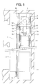
- Fig. 1 is a longitudinal sectional view showing an elevator apparatus according to
Embodiment 1 of the present invention; - Fig. 2 is a cross sectional view showing the elevator apparatus of Fig. 1;
- Fig. 3 is a longitudinal sectional view showing an elevator apparatus according to Embodiment 2 of the present invention;
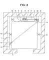
- Fig. 4 is a cross sectional view showing the elevator apparatus of Fig. 3;
- Fig. 5 is a longitudinal sectional view showing an elevator apparatus according to Embodiment 3 of the present invention;
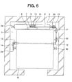
- Fig. 6 is a cross sectional view showing the elevator apparatus of Fig. 5.
- Hereinbelow, preferred embodiments of the present invention are described with reference to the drawings.
- Fig. 1 is a longitudinal sectional view showing an elevator apparatus according to
Embodiment 1 of the present invention, and Fig. 2 is a cross sectional view showing the elevator apparatus of Fig. 1. - Referring to the figures, a pair of
car guide rails counterweight guide rails hoistway 1. Acar 4 is arranged between thecar guide rails counterweight 5 is arranged between thecounterweight guide rails car 4 is guided by thecar guide rails hoistway 1. Thecounterweight 5 is guided by thecounterweight guide rails hoistway 1. - It should be noted that the elevator apparatus shown in Figs. 1 and 2 is a counterweight side drop type elevator apparatus in which the
car 4 and thecounterweight 5 are adjacent to each other with respect to the width direction of thecar 4 as seen in the vertical projection plane of thehoistway 1. Further, as seen in the vertical projection plane of thehoistway 1, the line connecting thecar guide rails counterweight guide rails - A horizontally extending
support member 6 is fixed to top portions of thecounterweight guide rails car 4 and thecounterweight 5 is supported on thesupport member 6. Thedrive device 7 has a drive devicemain body 8 including a motor, and adrive sheave 9 that is rotated by the drive devicemain body 8. Further, thedrive device 7 is a hoisting machine whose dimension in the axial direction of thedrive sheave 9 is smaller than its dimension in the direction perpendicular to the axis of thedrive sheave 9, that is, thedrive device 7 is a thin hoisting machine. Further, thedrive device 7 is arranged above thecounterweight 5. Furthermore, as seen in the vertical projection plane of thehoistway 1, thedrive device 7 is arranged outside the region of thecar 4 and inside the region of the counterweight 5 (Fig. 2). In this example, thedrive device 7 is arranged such that, as seen in the vertical projection plane of thehoistway 1, the axis of thedrive sheave 9 passes through the center of the line connecting thecounterweight guide rails - Provided at a top portion of the
counterweight guide rail 3a is adeflector sheave 10 that is arranged spaced from thedrive sheave 9. As seen in the vertical projection plane of thehoistway 1, thedeflector sheave 10 is arranged outside the respective regions of thecar 4 and counterweight 5 (Fig. 2). Further, as seen in the vertical projection plane of thehoistway 1, thedeflector sheave 10 is arranged within the range of the thickness of the counterweight 5 (the length of thecounterweight 5 with respect to the direction perpendicular to the line connecting thecounterweight guide rails car 4 than thecar guide rail 2a and farther away from thecounterweight 5 than thecounterweight guide rail 3a (Fig. 2). - A plurality of
main ropes 11 are wound around thedrive sheave 9. Provided at a lower end portion of thecar 4 are a pair ofcar suspension sheaves 12 around which themain ropes 11 are wound. Provided at an upper end portion of thecounterweight 5 is acounterweight suspension sheave 13 around which themain ropes 11 are wound. In this example, the line connecting thecar suspension sheaves 12 to each other extends parallel to the line connecting thecar guide rails - A first
rope securing portion 14 is fixed to a top portion of thecar guide rail 2b. A secondrope securing portion 15 is fixed to thesupport member 6. Eachmain rope 11 has afirst end portion 11a connected to the firstrope securing portion 14, and asecond end portion 11b connected to the secondrope securing portion 15. Further, starting from thefirst end portion 11a, themain ropes 11 are wound around the pair ofcar suspension sheaves 12, thedeflector sheave 10, thedrive sheave 9, and the counterweight suspension sheave 13 in the stated order before reaching thesecond end portion 11b. That is, the main ropes.11 are wound around thedrive sheave 9 and thedeflector sheave 10, thus suspending thecar 4 on one end side and thecounterweight 5 on the other end side. Further, each.main rope 11 has an outer layer portion (covering material) (not shown) formed of a high-friction material (resin) having a high friction coefficient in order to prevent slippage of themain rope 11 with respect to the pair ofcar suspension sheaves 12, thedeflector sheave 10, thedrive sheave 9, and thecounterweight suspension sheave 13. - In the elevator apparatus as described above, as seen in the vertical projection plane of the
hoistway 1, thedrive device 7 and thedeflector sheave 13 are arranged outside the region of thecar 4, whereby thecar 4 can be raised to a position where the ceiling level of thecar 4 exceeds the installation heights of thedrive device 7 anddeflector sheave 13. Furthermore, as seen in the vertical projection plane of thehoistway 1, thedrive sheave 9 can be arranged at a spacing from thecar suspension sheaves 12, which makes it unnecessary to arrange thedrive sheave 9 in close proximity to both thecar suspension sheaves 12 and thecounterweight suspension sheave 13, whereby the range where thedrive device 7 can be installed in thehoistway 1 can be enlarged. As a result, thedrive device 7 can be arranged at a position closer to thecar 4 while avoiding interference with thecar guide rail 2a, thecounterweight guide rail 3a, and the like, thereby achieving a reduction in the space required by thehoistway 1. - Further, by changing the respective positions of the
deflector sheave 10, thecar suspension sheaves 12, and thecar guide rails 2a, it is possible to widen the spacing between thecounterweight guide rails counterweight 5, whereby the dimension in the thickness direction of thecounterweight 5 can be reduced. Accordingly, a reduction in the requisite space of thehoistway 1 can be achieved. - Further, as seen in the vertical projection plane of the
hoistway 1, thedrive device 7 is arranged within the region of thecounterweight 5, thus enabling efficient utilization of space with respect to the vertical direction of thehoistway 1. Further, thedrive device 7 can be arranged within the range of the thickness of thecounterweight 5, thus allowing a further reduction in the requisite space of thehoistway 1. - Further, each
main rope 11 has the outer layer portion formed of a high-friction material, thereby making it possible to prevent slippage of themain rope 11 with respect to thedrive sheave 9, thedeflector sheave 10, the pair ofcar suspension sheaves 12, and thecounterweight suspension sheave 13. - While in the above-described example the entirety of the
drive device 7 is arranged within the region of thecounterweight 5 as seen in the vertical projection plane of thehoistway 1, as long as a reduction in the horizontal sectional area of thehoistway 1 can be achieved, it is also possible to arrange a part of thedrive device 7 within the region of thecounterweight 5 or to arrange thedrive device 7 outside the region of thecounterweight 5. - Further, while in the above-described example the line connecting the
car suspension sheaves 12 to each other is parallel to the line connecting thecar guide rails hoistway 1, the line connecting thecar suspension sheaves 12 to each other may be inclined with respect to the line connecting thecar guide rails car suspension sheaves 12 being arranged at symmetrical positions about the center of gravity of thecar 4. - Fig. 3 is a longitudinal sectional view showing an elevator apparatus according to Embodiment 2 of the present invention, and Fig. 4 is a cross sectional view showing the elevator apparatus of Fig. 3. The elevator apparatus shown in Figs. 3 and 4 is a counterweight rear drop type elevator apparatus in which, as seen in the vertical projection plane of a
hoistway 1, acar 4 and acounterweight 5 are adjacent to each other with respect to the depth direction of thecar 4. Further, as seen in the vertical projection plane of thehoistway 1, the line connectingcounterweight guide rails car guide rails - A
support member 6 is fixed to top portions of thecounterweight guide rails drive device 7 is supported on thesupport member 6. Thedrive device 7 has a drive devicemain body 8 and adrive sheave 9 that is rotated by the drive devicemain body 8. Further, as seen in the vertical projection plane of thehoistway 1, thedrive device 7 is arranged outside the region of thecar 4 and inside the region of the counterweight 5 (Fig. 4). - Provided at a top portion of the
counterweight guide rail 3b is adeflector sheave 21 spaced from thedrive sheave 9. As seen in the vertical projection plane of thehoistway 1, thedeflector sheave 21 is arranged outside the respective regions of thecar 4 andcounterweight 5 and within the range of the thickness of the counterweight 5 (the thickness of thecounterweight 5 with respect to the direction perpendicular to the line connecting thecounterweight guide rails - A pair of car suspension sheaves 12 are provided at a lower end portion of the
car 4. One of the car suspension sheaves 12 is arranged in close proximity to thedeflector sheave 21 as seen in the vertical projection plane of thehoistway 1. As seen in the vertical projection plane of thehoistway 1, the line connecting the car suspension sheaves 12 to each other is inclined with respect to the width direction of thecar 4 and passes through a position near the center of gravity of the car 4 (Fig. 4). - A
counterweight suspension sheave 13 is provided at a lower end portion of thecounterweight 5. The respective axes of thedrive sheave 9,counterweight suspension sheave 13, anddeflector sheave 21 are parallel to each other. - A first
rope securing portion 14 is fixed at a top portion of thehoistway 1. A secondrope securing portion 15 is fixed to thesupport member 6. Afirst end portion 11a of amain rope 11 is connected to the firstrope securing portion 14 and thesecond end portion 11b of themain rope 11 is connected to the secondrope securing portion 15. Starting from thefirst end portion 11a, themain rope 11 is wound around the pair of car suspension sheaves 12, thedeflector sheave 21, thedrive sheave 9, and thecounterweight suspension sheave 13 in the stated order before reaching thesecond end portion 11b. Otherwise, Embodiment 2 is of the same construction asEmbodiment 1. - In the elevator apparatus as described above, the
drive device 7 and thedeflector sheave 21 are arranged outside the region of thecar 4 as seen in the vertical projection plane of thehoistway 1, whereby, as inEmbodiment 1, the range where thedrive device 7 can be installed in thehoistway 1 can be enlarged, thus allowing a reduction in the requisite space of thehoistway 1. - Fig. 5 is a longitudinal sectional view showing an elevator apparatus according to Embodiment 3 of the present invention, and Fig. 6 is a cross sectional view showing the elevator apparatus of Fig. 5. In this example, a pair of return pulleys, a
first return pulley 31 and asecond return pulley 32, is provided at a top portion of ahoistway 1. As seen in the vertical projection plane of thehoistway 1, thefirst return pulley 31 and thesecond return pulley 32 are arranged outside the respective regions of acar 4 and a counterweight 5 (Fig. 6). The respective axes of thefirst return pulley 31 andsecond return pulley 32 are perpendicular to the axis of adeflector sheave 21. Further, as seen in the vertical projection plane of thehoistway 1, the line connecting the respective centers of thefirst return pulley 31 andsecond return pulley 32 is perpendicular to the line connecting the respective centers of adrive sheave 9 and the deflector sheave 21 (Fig. 6). Furthermore, thefirst return pulley 31 is positioned lower than thesecond return pulley 32 and, as seen in the vertical projection plane of thehoistway 1, arranged on thedeflector sheave 21 side with respect tosecond return pulley 32. - Starting from its
first end portion 11a, amain rope 11 is wound around a pair of car suspension sheaves 12, thesecond return pulley 32, thefirst return pulley 31, thedeflector sheave 21, thedrive sheave 9, and acounterweight suspension sheave 13 in the stated order before reaching asecond end portion 11b. Otherwise, Embodiment 3 is of the same construction asEmbodiment 1. - In the elevator apparatus as described above, as seen in the vertical projection plane of the
hoistway 1, thefirst return pulley 31 and thesecond return pulley 32, around each of which themain rope 11 is wound, are arranged outside the region of thecar 4, whereby thecar 4 can be raised to a position where the ceiling level of thecar 4 exceeds the installation heights of the first and second return pulleys 31, 32. Moreover, eachcar suspension sheave 12 can be arranged at a spacing from thedeflector sheave 21 as seen in the vertical projection plane of thehoistway 1, thereby enhancing the degree of freedom in the arrangement of the car suspension sheaves 12 in thecar 4. - While in the above-described example the pair of the first and second return pulleys 31, 32 is provided in the
hoistway 1, two or more pairs of the first and second return pulleys 31, 32 may also be provided in thehoistway 1.
Claims (4)
- An elevator apparatus characterized by comprising:a car and a counterweight that are capable of being raised and lowered in a hoistway;a drive device having a drive sheave and arranged outside a region of the car as seen in a vertical projection plane of the hoistway, for raising and lowering the car and the counterweight;a deflector sheave spaced from the drive sheave and arranged outside the region of the car as seen in the vertical projection plane of the hoistway; anda main rope wound around the drive sheave and the deflector sheave, for suspending the car and the counterweight.
- An elevator apparatus according to Claim 1, characterized in that at least a part of the drive device is arranged inside a region of the counterweight as seen in the vertical projection plane of the hoistway.
- An elevator apparatus according to Claim 1 or 2, characterized by further comprising a pair of return pulleys around which the main rope is wound and which are arranged outside the region of the car as seen in the vertical projection plane of the hoistway.
- An elevator apparatus according to any one of Claims 1 through 3, characterized in that the main rope has an outer layer portion formed of a high-friction material.
Applications Claiming Priority (1)
| Application Number | Priority Date | Filing Date | Title |
|---|---|---|---|
| PCT/JP2004/001393 WO2005075335A1 (en) | 2004-02-10 | 2004-02-10 | Elevator |
Publications (2)
| Publication Number | Publication Date |
|---|---|
| EP1714934A1 true EP1714934A1 (en) | 2006-10-25 |
| EP1714934A4 EP1714934A4 (en) | 2011-07-06 |
Family
ID=34835774
Family Applications (1)
| Application Number | Title | Priority Date | Filing Date |
|---|---|---|---|
| EP04709701A Withdrawn EP1714934A4 (en) | 2004-02-10 | 2004-02-10 | LIFTS |
Country Status (4)
| Country | Link |
|---|---|
| EP (1) | EP1714934A4 (en) |
| JP (1) | JPWO2005075335A1 (en) |
| CN (1) | CN1741953B (en) |
| WO (1) | WO2005075335A1 (en) |
Families Citing this family (3)
| Publication number | Priority date | Publication date | Assignee | Title |
|---|---|---|---|---|
| CN102815588B (en) * | 2011-06-10 | 2015-05-13 | 铃木电梯(中国)有限公司 | Pulley block in multifunctional elevator and multifunctional elevator obtained therefrom |
| KR101690856B1 (en) * | 2012-07-04 | 2016-12-28 | 미쓰비시덴키 가부시키가이샤 | Elevator device |
| CN105712165A (en) * | 2016-04-07 | 2016-06-29 | 江南嘉捷电梯股份有限公司 | Layout structure of machine-roomless elevator |
Family Cites Families (10)
| Publication number | Priority date | Publication date | Assignee | Title |
|---|---|---|---|---|
| WO1999043593A1 (en) * | 1998-02-26 | 1999-09-02 | Otis Elevator Company | Elevator system with overhead drive motor |
| JPH11310372A (en) * | 1998-04-28 | 1999-11-09 | Toshiba Elevator Co Ltd | Elevator equipment |
| JP3724322B2 (en) * | 2000-03-15 | 2005-12-07 | 株式会社日立製作所 | Wire rope and elevator using it |
| JP2001261257A (en) * | 2000-03-23 | 2001-09-26 | Mitsubishi Electric Corp | Elevator equipment |
| JP4557401B2 (en) * | 2000-09-19 | 2010-10-06 | 東芝エレベータ株式会社 | elevator |
| JP4849712B2 (en) * | 2000-11-08 | 2012-01-11 | 東芝エレベータ株式会社 | elevator |
| JP4771587B2 (en) | 2000-12-19 | 2011-09-14 | 東芝エレベータ株式会社 | elevator |
| JP4825368B2 (en) * | 2001-07-10 | 2011-11-30 | 東芝エレベータ株式会社 | Elevator equipment |
| WO2003008318A1 (en) * | 2001-07-11 | 2003-01-30 | Mitsubishi Denki Kabushiki Kaisha | Elevator device |
| JP2004001919A (en) * | 2002-05-30 | 2004-01-08 | Otis Elevator Co | Elevator device |
-
2004
- 2004-02-10 CN CN200480002613.3A patent/CN1741953B/en not_active Expired - Fee Related
- 2004-02-10 WO PCT/JP2004/001393 patent/WO2005075335A1/en not_active Ceased
- 2004-02-10 JP JP2005517608A patent/JPWO2005075335A1/en active Pending
- 2004-02-10 EP EP04709701A patent/EP1714934A4/en not_active Withdrawn
Non-Patent Citations (2)
| Title |
|---|
| No further relevant documents disclosed * |
| See also references of WO2005075335A1 * |
Also Published As
| Publication number | Publication date |
|---|---|
| EP1714934A4 (en) | 2011-07-06 |
| WO2005075335A1 (en) | 2005-08-18 |
| CN1741953B (en) | 2012-10-31 |
| CN1741953A (en) | 2006-03-01 |
| JPWO2005075335A1 (en) | 2007-08-23 |
Similar Documents
| Publication | Publication Date | Title |
|---|---|---|
| KR100966534B1 (en) | Elevator system with multiple cars in hoistway | |
| US20110108366A1 (en) | Elevator apparatus | |
| KR100444936B1 (en) | Elevator device | |
| JP4919359B2 (en) | Elevator car | |
| EP1327596B1 (en) | Elevator device | |
| EP1564177B1 (en) | Elevator equipment | |
| EP1714934A1 (en) | Elevator | |
| EP1568644B9 (en) | Elevator equipment | |
| EP1832543A1 (en) | Elevator apparatus | |
| EP2019072A1 (en) | Elevator device | |
| EP1717185B1 (en) | Elevator | |
| EP1724229A1 (en) | Elevator apparatus | |
| JP4291131B2 (en) | Elevator equipment | |
| US20070170005A1 (en) | Machine room-less elevator | |
| JP2008168986A (en) | Elevator equipment | |
| EP1571113B1 (en) | Elevator equipment | |
| JP2005212941A (en) | Connecting device for elevator main rope | |
| KR100735338B1 (en) | Elevator device | |
| EP1500620A1 (en) | Elevator | |
| EP1520830B1 (en) | Elevator device | |
| EP1314680B1 (en) | Elevator device | |
| EP1602611B1 (en) | Elevator apparatus | |
| JP2006151625A (en) | Elevator equipment | |
| KR100795265B1 (en) | Elevator device | |
| CN121085078A (en) | Elevator device |
Legal Events
| Date | Code | Title | Description |
|---|---|---|---|
| PUAI | Public reference made under article 153(3) epc to a published international application that has entered the european phase |
Free format text: ORIGINAL CODE: 0009012 |
|
| 17P | Request for examination filed |
Effective date: 20050823 |
|
| AK | Designated contracting states |
Kind code of ref document: A1 Designated state(s): DE |
|
| DAX | Request for extension of the european patent (deleted) | ||
| RBV | Designated contracting states (corrected) |
Designated state(s): DE |
|
| RBV | Designated contracting states (corrected) |
Designated state(s): DE |
|
| A4 | Supplementary search report drawn up and despatched |
Effective date: 20110609 |
|
| 17Q | First examination report despatched |
Effective date: 20120619 |
|
| STAA | Information on the status of an ep patent application or granted ep patent |
Free format text: STATUS: THE APPLICATION IS DEEMED TO BE WITHDRAWN |
|
| 18D | Application deemed to be withdrawn |
Effective date: 20140511 |