EP1714929A1 - Walzenantrieb - Google Patents
Walzenantrieb Download PDFInfo
- Publication number
- EP1714929A1 EP1714929A1 EP06111073A EP06111073A EP1714929A1 EP 1714929 A1 EP1714929 A1 EP 1714929A1 EP 06111073 A EP06111073 A EP 06111073A EP 06111073 A EP06111073 A EP 06111073A EP 1714929 A1 EP1714929 A1 EP 1714929A1
- Authority
- EP
- European Patent Office
- Prior art keywords
- drive
- roll
- synchronous motor
- roller
- motor
- Prior art date
- Legal status (The legal status is an assumption and is not a legal conclusion. Google has not performed a legal analysis and makes no representation as to the accuracy of the status listed.)
- Granted
Links
- 230000001360 synchronised effect Effects 0.000 claims abstract description 23
- 238000012545 processing Methods 0.000 claims abstract description 4
- 238000004804 winding Methods 0.000 claims description 18
- 239000000463 material Substances 0.000 claims description 5
- 238000001816 cooling Methods 0.000 claims description 2
- 238000005096 rolling process Methods 0.000 claims description 2
- 238000004519 manufacturing process Methods 0.000 abstract description 2
- 239000000123 paper Substances 0.000 abstract description 2
- 239000011087 paperboard Substances 0.000 abstract description 2
- 239000000109 continuous material Substances 0.000 abstract 1
- 238000009434 installation Methods 0.000 description 2
- 238000012423 maintenance Methods 0.000 description 2
- 238000003860 storage Methods 0.000 description 2
- 239000011111 cardboard Substances 0.000 description 1
- 238000010276 construction Methods 0.000 description 1
- 238000013461 design Methods 0.000 description 1
- 230000000694 effects Effects 0.000 description 1
- 230000001050 lubricating effect Effects 0.000 description 1
- 238000005461 lubrication Methods 0.000 description 1
- 238000012544 monitoring process Methods 0.000 description 1
- 238000012549 training Methods 0.000 description 1
Images

Classifications
-
- H—ELECTRICITY
- H02—GENERATION; CONVERSION OR DISTRIBUTION OF ELECTRIC POWER
- H02K—DYNAMO-ELECTRIC MACHINES
- H02K7/00—Arrangements for handling mechanical energy structurally associated with dynamo-electric machines, e.g. structural association with mechanical driving motors or auxiliary dynamo-electric machines
- H02K7/10—Structural association with clutches, brakes, gears, pulleys or mechanical starters
- H02K7/1004—Structural association with clutches, brakes, gears, pulleys or mechanical starters with pulleys
- H02K7/1012—Machine arranged inside the pulley
- H02K7/1016—Machine of the outer rotor type
-
- B—PERFORMING OPERATIONS; TRANSPORTING
- B65—CONVEYING; PACKING; STORING; HANDLING THIN OR FILAMENTARY MATERIAL
- B65H—HANDLING THIN OR FILAMENTARY MATERIAL, e.g. SHEETS, WEBS, CABLES
- B65H27/00—Special constructions, e.g. surface features, of feed or guide rollers for webs
-
- D—TEXTILES; PAPER
- D21—PAPER-MAKING; PRODUCTION OF CELLULOSE
- D21F—PAPER-MAKING MACHINES; METHODS OF PRODUCING PAPER THEREON
- D21F7/00—Other details of machines for making continuous webs of paper
- D21F7/02—Mechanical driving arrangements
-
- B—PERFORMING OPERATIONS; TRANSPORTING
- B65—CONVEYING; PACKING; STORING; HANDLING THIN OR FILAMENTARY MATERIAL
- B65H—HANDLING THIN OR FILAMENTARY MATERIAL, e.g. SHEETS, WEBS, CABLES
- B65H2404/00—Parts for transporting or guiding the handled material
- B65H2404/10—Rollers
- B65H2404/16—Details of driving
- B65H2404/162—Details of driving containing, enclosing own driving means
Definitions
- the invention relates to a drive for a roll of a machine for producing and / or processing a moving material web, in particular a paper or board web, wherein the driven roller each having its own electric drive motor with a rotor and a stator.
- Such a drive system for winding machines is in the DE-U-20209537 described.
- From the EP-A2-1460010 is the direct drive of a winding core of a winding roll with an electric motor, which is preferably a synchronous motor, removable. Said electric motor is arranged coaxially with the winding roller and coupled to a rotary drive.
- the invention is therefore based on the object to provide a roller drive, with which the disadvantages of the prior art are avoidable.
- the object of the invention is achieved with the characterizing features of claim 1. Accordingly, it is provided that a known synchronous motor is provided as the drive motor, which is arranged in the interior of the respective roller to be driven. This allows not only a torsion-resistant drive but also a higher efficiency of the machine. In addition, the installation and commissioning costs are covered less than before.
- An expedient embodiment of the invention is that the synchronous motor is arranged at a front end of the driven roller. From the operator, a good monitoring of the drive from one side of the machine (drive side) is possible.
- the driven roller is formed substantially hollow and has a continuous, rotatable roll shell and the frontally outstanding roll neck.
- the roll neck can be individual components.
- the roll neck can also be made as a single, the entire roller traversing component.
- the or the roll neck are fixed.
- a roll neck at the same time forms the stator and the rotatable roll shell forms the rotor of the synchronous motor. This embodiment is very advantageous because it creates a very simple but compact and low-maintenance design of the roller drive.
- a further advantageous embodiment consists in that the roll shell can be rotated by means of radial bearings, in particular rolling bearings, incorporated in the roll.
- the radial bearings are located respectively at the front ends of the roller.
- the drive or motor according to the invention thus does not require its own foundation for storage and does not need to be laboriously aligned, which represents a further advantage of the invention.
- means for lubricating the bearings of the roller are advantageously not necessary, but means for cooling the internal Synchronous motor can be very easily, for example, in the roll neck accommodate.
- the drive according to the invention can be used, in addition to other cylinders and rollers of a production or processing machine of a moving material web, particularly advantageously for carrier rollers and / or pressure rollers of a winding machine or rollers of a slitter-winder, which were previously driven by three-phase asynchronous motors.
- a driven roller 1 is shown in section.
- This cylindrical roller 1 is formed substantially hollow and can therefore accommodate a provided for the rotary drive of the roller 1 synchronous motor 2 record.
- the roll 1 has a continuous rotatable roll shell 1.2 and also at its front end 1.3 and 1.3. ' in each case a roll neck 1.4 and 1.4 ', which is designed to be stationary.
- the roll neck 1.4 is thus capable of the same time
- electrical connecting cable 3 projecting towards the drive side TS for the operation of the synchronous motor 2.
- the electrical connection cable 3 open into a winding 2.3 of the synchronous motor.
- the roll mantle 1.2 On the inner wall of the roll mantle 1.2 permanent magnets 2.4 (or a single concentric extending) are attached, the effect of the rotational movement of the roller 1 when the windings are subjected to the electrical current. During the rotational movement, therefore, only the roll shell 1.2 rotates over a plurality of radial bearings 4, which are pushed both on the roll neck 1.4, and on the opposite roll neck 1.4 '.
- the radial bearings 4 are here encapsulated bearings that are free of lubrication.
- the roll shell 1.2 is by its described rotation able to form at the same time the rotor 2.2 of the synchronous motor 2, whereby a total of a very compact, low maintenance and low-wear and quiet drive is present.
- FIG. 1 also shows a first variant of the arrangement of the bearing of the roll mantle 1.2.
- an additional radial bearing 4 is shown, which lies on the side facing away from the front end 1.3 side of the synchronous motor 2 and whereby a high stability and, above all, particularly good running properties of the roller 1 are ensured.
- FIG. 2 shows a second variant of the arrangement of the radial bearing 4 is shown.
- a radial bearing 4 or 4 ' is provided, which is here only at the two front end 1.3 and 1.3' of the roller 1. Otherwise, there are no further changes compared with FIG. 1 and therefore require no further explanation.
- the third variant shown in Figure 3 differs from the embodiment of Figure 2 only in that the roll neck 1.4 is formed continuously. Like in FIG. 2, only the two end radial bearings 4 and 4 'are present. This training is provided with very wide machines for stability reasons with correspondingly long rollers 1.
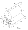
- FIG. 4 shows and describes an application possibility of the roller drive according to the invention, which in the example is a winding machine.
- the winding machine has two driven support rollers 5 and 6, which is a support bed for a winding roll 7 when winding a non-illustrated material web, in particular a web of paper or cardboard. Shown is also a pressure roller 8, with a fixed winding to be achieved. The wound web of material is thereby pressed against the winding so that entrained air is squeezed with the web to be wrapped.
- the rollers 5, 6 and 8 shown correspond to the roller 1 of Figures 1 to 3 and therefore each have a drive according to the invention or drive motor in the form of the known synchronous motor 2.
- This synchronous motor 2 is installed in each case in the interior of the relevant roller to be driven 5, 6, 8. Recognizable in Figure 4 again from each of the end faces or front ends 1.3 of the rollers 5, 6. 8 projecting roll neck 1.4 and the radial bearings 4. From these roll journals 1.4 in turn project to the drive side TS of the winding machine out the electrical connection cable 3, respectively go out of the not visible here winding 2.3 of the also not visible synchronous motor
Landscapes
- Engineering & Computer Science (AREA)
- Power Engineering (AREA)
- Mechanical Engineering (AREA)
- Rolls And Other Rotary Bodies (AREA)
- Friction Gearing (AREA)
- Valve Device For Special Equipments (AREA)
- Manufacture Of Motors, Generators (AREA)
- Paper (AREA)
Abstract
Description
- Die Erfindung betrifft einen Antrieb für eine Walze einer Maschine zur Herstellung und/oder Bearbeitung einer laufenden Materialbahn, insbesondere einer Papier- oder Kartonbahn, wobei die anzutreibende Walze jeweils einen eigenen elektrischen Antriebsmotor mit einem Rotor und einen Stator aufweist.
- Ein derartiges Antriebssystem für Wickelmaschinen ist in der
DE-U-20209537 beschrieben. - Aus der
EP-A2-1460010 ist der Direktantrieb eines Wickelkerns einer Wickelrolle mit einem Elektromotor, der vorzugsweise ein Synchronmotor ist, entnehmbar. Der besagte Elektromotor ist hierbei koaxial zur Wickelwalze angeordnet und an einen Drehantrieb gekoppelt. - Diese Bauweise und die Installation sind relativ aufwändig. Außerdem stören die Motore und Kupplungen die Peripherie der Maschine, in der die anzutreibenden Walzen sich befinden und nehmen unnötig viel Platz in Anspruch.
- Der Erfindung liegt daher die Aufgabe zugrunde, einen Walzenantrieb zu schaffen, mit dem die Nachteile des Standes der Technik vermeidbar sind.
- Die Aufgabe der Erfindung wird mit den kennzeichnenden Merkmalen des Anspruches 1 gelöst.
Demgemäß ist vorgesehen, dass als Antriebsmotor ein an sich bekannter Synchronmotor vorgesehen ist, der im Inneren der betreffenden anzutreibenden Walze angeordnet ist.
Dadurch wird neben einem torsionssteifen Antrieb auch ein höherer Wirkungsgrad der Maschine ermöglicht. Außerdem fallen die Montage- und Inbetriebnahmekosten geringer als bisher aus. - Eine zweckmäßige Ausgestaltung der Erfindung besteht darin, dass der Synchronmotor an einem stirnseitigen Ende der anzutreibenden Walze angeordnet ist. Vom Bedienpersonal ist dadurch eine gute Überwachung des Antriebes von einer Maschinenseite (Triebseite) aus möglich.
- Im Rahmen der Erfindung ist außerdem vorgesehen, dass die anzutreibende Walze im Wesentlichen hohl ausgebildet ist und einen durchgehenden, drehbaren Walzenmantel sowie stirnseitig herausragende Walzenzapfen aufweist. Die Walzenzapfen können dabei einzelne Bauteile sein. Der Walzenzapfen kann aber auch als ein einziges, die gesamte Walze durchquerendes Bauteil gefertigt sein. Dabei sind die oder der Walzenzapfen feststehend ausgebildet. Erfindungsgemäß ist vorgesehen, dass ein Walzenzapfen zugleich den Stator und der drehbare Walzenmantel den Rotor des Synchronmotors bildet. Diese Ausgestaltung ist sehr vorteilhaft, weil damit eine sehr einfache, aber kompakte und wartungsarme Bauweise des Walzenantriebes geschaffen wird.
- Eine weitere vorteilhafte Ausgestaltung besteht darin, dass der Walzenmantel über in der Walze eingebaute Radiallager, insbesondere Wälzlager, drehbar ist. Die Radiallager befinden sich jeweils an den stirnseitigen Enden der Walze. Der erfindungsgemäße Antrieb bzw. Motor benötigt dadurch kein eigenes Fundament zur Lagerung und braucht auch nicht aufwändig ausgerichtet zu werden, was einen weiteren Vorteil der Erfindung darstellt.
- Je nach der Größe und der Drehzahl der anzutreibenden Walze ist es sinnvoll, wenn ein weiteres Radiallager sich auch an der von der ersten Stirnseite abgewandten Seite des Synchronmotors befindet. Dadurch können die Laufeigenschaften der Walze verbessert werden.
- Nachzutragen ist, dass Mittel zur Schmierung der Lagerstellen der Walze in vorteilhafter Weise nicht notwenig sind, aber Mittel zur Kühlung des innen liegenden Synchronmotors lassen sich sehr einfach beispielsweise in den Walzenzapfen unterbringen.
- Der erfindungsgemäße Antrieb lässt sich neben anderen anzutreibenden Zylindern und Walzen einer Herstellungs- oder Bearbeitungsmaschine einer laufenden Materialbahn besonders vorteilhaft für Tragwalzen und/ oder Andrückwalzen einer Wickelmaschine oder Walzen einer Rollenschneidmaschine einsetzen, die bisher mit Drehstromasynchronmotoren angetrieben wurden.
- Nachfolgend soll die Erfindung anhand eines Ausführungsbeispieles näher erläutert werden.
- Es zeigt:
- In den einzelnen Figuren sind gleiche Bauteile mit gleichem Bezugszeichen versehen oder ganz weggelassen, weil sie gegenüber der vorher erläuterten Figur selbsterklärend sind.
- Figuren 1 bis 3:
- den Schnitt durch jeweils eine Walze mit der Anordung des erfindungsgemäßen Antriebs und Varianten der Lagerung
- Figur 4:
- in perspektivischer, aber nur schematischer Darstellung ein Anwendungsbeispiel in Form einer Wickelmaschine, deren Tragwalzen und eine Andrückwalze mit einem erfindungsgemäßen Antrieb ausgerüstet sind
- In Figur 1 ist eine anzutreibende Walze1 im Schnitt dargestellt. Diese zylindrische Walze 1 ist im Wesentlichen hohl ausgebildet ist und kann deshalb einen für den Drehantrieb der Walze 1 vorgesehenen Synchronmotor 2 aufnehmen. Die Walze 1 weist einen durchgehenden rotierbaren Walzenmantel 1.2 und außerdem an ihrem stirnseitigen Ende 1.3 und 1.3.' jeweils einen Walzenzapfen 1.4 und 1.4' auf, der feststehend ausgebildet ist. Der Walzenzapfen 1.4 ist somit in der Lage zugleich den Stator 2.1 des eingebauten Synchronmotors 2 zu bilden. Eingelassen in den Walzenzapfen 1.4 sind zur Triebseite TS hin ragende elektrische Anschlusskabel 3 für den Betrieb des Synchronmotors 2. Die elektrischen Anschlusskabel 3 münden in eine Wicklung 2.3 des Synchronmotors.
An der Innenwandung des Walzenmantels 1.2 sind Permanentmagnete 2.4 (oder ein einzelner konzentrisch verlaufender) befestigt, die oder der bei der Beaufschlagung der Wicklungen mit elektrischen Strom die Drehbewegung der Walze 1 bewirken/bewirkt. Bei der Drehbewegung dreht sich also nur der Walzenmantel 1.2 über mehrere Radiallager 4, die sowohl auf den Walzenzapfen 1.4, als auch auf den gegenüberliegenden Walzenzapfen 1.4' aufgeschoben sind. Die Radiallager 4 sind hier eingekapselte Wälzlager, die schmierfrei sind.
Der Walzenmantel 1.2 ist durch seine beschriebene Drehbarkeit in der Lage, zugleich den Rotor 2.2 des Synchronmotors 2 zu bilden, wodurch insgesamt ein sehr kompakter, wartungs- und verschleißarmer und auch geräuscharmer Antrieb vorliegt. - Figur 1 zeigt auch eine erste Variante der Anordnung der Lagerung des Walzenmantels 1.2. Dabei ist ein zusätzliches Radiallager 4" dargestellt, welches auf der vom stirnseitigen Ende 1.3 abgewandten Seite des Synchronmotors 2 liegt und wodurch eine hohe Stabilität und vor allem besonders gute Laufeigenschaften der Walze 1 gewährleistet werden.
- In Figur 2 ist eine zweite Variante der Anordnung des Radiallagers 4 dargestellt. Hierbei ist nur ein Radiallager 4 bzw. 4' vorgesehen, welches sich hier nur an den beiden stirnseitigen Ende 1.3 und 1.3' der Walze 1 befindet. Ansonsten bestehen keine weiteren Veränderungen gegenüber der Figur 1 und bedürfen deshalb keiner weiteren Erläuterung.
- Die in Figur 3 gezeigte dritte Variante weicht von der Ausführung gemäß Figur 2 nur dadurch ab, dass der Walzenzapfen 1.4 durchgehend ausgebildet ist. Es sind ebenfalls wie bei Figur 2 nur die beiden stirnseitigen Radiallager 4 bzw. 4' vorhanden. Diese Ausbildung ist bei sehr breiten Maschinen aus Stabilitätsgründen mit dementsprechend langen Walzen 1 vorgesehen.
- In der Figur 4 ist eine Anwendungsmöglichkeit des erfindungsgemäßen Walzenantriebes gezeigt und beschrieben, bei der es sich im Beispiel um eine Wickelmaschine handelt.
- Die Wickelmaschine weist zwei angetriebene Tragwalzen 5 und 6 auf, die ein Tragbett für eine Wickelrolle 7 beim Aufwickeln einer nicht mit dargestellten Materialbahn, insbesondere einer Bahn aus Papier oder Karton darstellt. Gezeigt ist auch eine Andrückwalze 8, mit der ein fester Wickel erreicht werden soll. Die aufzuwickelnde Materialbahn wird dadurch so gegen den Wickel gedrückt, dass mit der zu wickelnden Bahn eingeschleppte Luft abgequetscht wird. Die gezeigten Walzen 5, 6 und 8 entsprechen der Walze 1 aus den Figuren 1 bis 3 und weisen deshalb jeweils einen erfindungsgemäßen Antrieb bzw. Antriebsmotor in Form des an sich bekannten Synchronmotors 2 auf. Dieser Synchronmotor 2 ist jeweils im Inneren der betreffenden anzutreibenden Walze 5, 6, 8 eingebaut. Erkennbar sind in Figur 4 wieder jeweils die aus den Stirnseiten bzw. stirnseitigen Enden 1.3 der Walzen 5, 6. 8 ragende Walzenzapfen 1.4 und die Radiallager 4. Aus diesen Walzenzapfen 1.4 ragen wiederum zur Triebseite TS der Wickelmaschine hin die elektrischen Anschlusskabel 3, die jeweils von der hier nicht sichtbaren Wicklung 2.3 des ebenfalls nicht sichtbaren Synchronmotors 2 ausgehen.
-
- 1
- Walze
- 1.2
- Walzenmantel
- 1.3, 1.3'
- stirnseitiges Ende
- 1.4, 1.4'
- Walzenzapfen
- 2
- Synchronmotor
- 2.1
- Stator
- 2.2
- Rotor
- 2.3
- Wicklung
- 2.4
- Permanentmagnet
- 3
- elektrisches Anschlußkabel
- 4, 4', 4"
- Radiallager
- 5
- Tragwalze
- 6
- Tragwalze
- 7
- Wickelrolle
- 8
- Andrückwalze
- TS
- Triebseite
Claims (7)
- Antrieb für eine Walze einer Maschine zur Herstellung und/oder Bearbeitung einer laufenden Materialbahn, insbesondere einer Papier- oder Kartonbahn, wobei die anzutreibende Walze (1) jeweils einen eigenen elektrischen Antriebsmotor mit einem Rotor und einen Stator aufweist,
dadurch gekennzeichnet, dass
als Antriebsmotor ein Synchronmotor (2) vorgesehen ist, der im Inneren der betreffenden anzutreibenden Walze (1, 5, 6, 8) angeordnet ist. - Antrieb nach Anspruch 1,
dadurch gekennzeichnet, dass
der Synchronmotor (2) an wenigstens einem stirnseitigen Ende (1.3) der anzutreibenden Walze (1, 5, 6, 8) angeordnet ist. - Antrieb Anspruch 1 und 2,
dadurch gekennzeichnet, dass
die anzutreibende Walze (1, 5, 6, 8) im Wesentlichen hohl ausgebildet ist und einen durchgehenden Walzenmantel (1.2) und stirnseitige Walzenzapfen (1.4, 1.4') aufweist, wobei die Walzenzapfen (1.4, 1.4') feststehend ausgebildet sind und den Stator (2.1) des Synchronmotors (2) und der drehbare Walzenmantel (1.2) den Rotor (2.2) des Synchronmotors (2) bildet. - Antrieb nach Anspruch 1 bis 3,
dadurch gekennzeichnet, dass
der Walzenmantel (1.2) über an den stirnseitigen Enden (1.3) der Walze (1, 5, 6, 8) eingebaute Radiallager (4, 4'), insbesondere Wälzlager, drehbar ist. - Antrieb nach Anspruch 4,
dadurch gekennzeichnet, dass
ein weiteres Radiallager (4") sich auch an der von der ersten Stirnseite (1.3) abgewandten Seite des Synchronmotors (2) befindet. - Antrieb nach Anspruch 1 bis 3,
dadurch gekennzeichnet, dass Mittel zur Kühlung des Synchronmotors (2) vorhanden sind. - Antrieb nach Anspruch 1 bis 3,
dadurch gekennzeichnet, dass er für Tragwalzen (5, 6) und/ oder Andrückwalzen (8) einer Wickelmaschine oder Walzen einer Rollenschneidmaschine vorgesehen ist.
Applications Claiming Priority (1)
| Application Number | Priority Date | Filing Date | Title |
|---|---|---|---|
| DE102005000037A DE102005000037A1 (de) | 2005-04-19 | 2005-04-19 | Walzenantrieb |
Publications (2)
| Publication Number | Publication Date |
|---|---|
| EP1714929A1 true EP1714929A1 (de) | 2006-10-25 |
| EP1714929B1 EP1714929B1 (de) | 2008-06-04 |
Family
ID=36649797
Family Applications (1)
| Application Number | Title | Priority Date | Filing Date |
|---|---|---|---|
| EP06111073A Revoked EP1714929B1 (de) | 2005-04-19 | 2006-03-14 | Walzenantrieb |
Country Status (3)
| Country | Link |
|---|---|
| EP (1) | EP1714929B1 (de) |
| AT (1) | ATE397563T1 (de) |
| DE (2) | DE102005000037A1 (de) |
Citations (8)
| Publication number | Priority date | Publication date | Assignee | Title |
|---|---|---|---|---|
| US5442248A (en) * | 1994-04-11 | 1995-08-15 | Interroll Holding, A.G. | Motorized pulley with integral electrical connector |
| DE19509288A1 (de) * | 1995-03-15 | 1996-09-26 | Rekam Engineering Gmbh | Drehzahl- und kraftsteuerbare Hohlwelle zum definierten Einsatz, insbesondere in Beschichtungs- oder Druckanlagen |
| DE19614936A1 (de) * | 1996-04-16 | 1997-10-23 | Intus Maschinen Gmbh | Modularer Trommelmotor |
| DE20209537U1 (de) | 2002-06-20 | 2002-08-29 | Voith Paper Patent GmbH, 89522 Heidenheim | Antriebssystem für eine Wickelmaschine |
| DE10153895A1 (de) * | 2001-11-02 | 2003-05-22 | Tonic Fitness Technology Inc | Walzeneinrichtung mit dynamischer Funktion |
| EP1331306A1 (de) * | 2002-01-28 | 2003-07-30 | Voith Paper Patent GmbH | Antriebseinheit |
| EP1460010A2 (de) | 2003-03-19 | 2004-09-22 | Voith Paper Patent GmbH | Maschine mit einem vorzugsweise als Synchronmotor ausgeführten und zum Direktantrieb eines Wickelkerns einer Wickelrolle dienenden Elektromotors, insbesondere zur Verwendung in der Papierindustrie, und sich hierauf beziehendes Umbauverfahren |
| DE10319105A1 (de) * | 2003-04-28 | 2004-11-18 | Voith Paper Patent Gmbh | Drehteil mit Drehantrieb |
-
2005
- 2005-04-19 DE DE102005000037A patent/DE102005000037A1/de not_active Withdrawn
-
2006
- 2006-03-14 DE DE502006000858T patent/DE502006000858D1/de not_active Expired - Lifetime
- 2006-03-14 EP EP06111073A patent/EP1714929B1/de not_active Revoked
- 2006-03-14 AT AT06111073T patent/ATE397563T1/de active
Patent Citations (8)
| Publication number | Priority date | Publication date | Assignee | Title |
|---|---|---|---|---|
| US5442248A (en) * | 1994-04-11 | 1995-08-15 | Interroll Holding, A.G. | Motorized pulley with integral electrical connector |
| DE19509288A1 (de) * | 1995-03-15 | 1996-09-26 | Rekam Engineering Gmbh | Drehzahl- und kraftsteuerbare Hohlwelle zum definierten Einsatz, insbesondere in Beschichtungs- oder Druckanlagen |
| DE19614936A1 (de) * | 1996-04-16 | 1997-10-23 | Intus Maschinen Gmbh | Modularer Trommelmotor |
| DE10153895A1 (de) * | 2001-11-02 | 2003-05-22 | Tonic Fitness Technology Inc | Walzeneinrichtung mit dynamischer Funktion |
| EP1331306A1 (de) * | 2002-01-28 | 2003-07-30 | Voith Paper Patent GmbH | Antriebseinheit |
| DE20209537U1 (de) | 2002-06-20 | 2002-08-29 | Voith Paper Patent GmbH, 89522 Heidenheim | Antriebssystem für eine Wickelmaschine |
| EP1460010A2 (de) | 2003-03-19 | 2004-09-22 | Voith Paper Patent GmbH | Maschine mit einem vorzugsweise als Synchronmotor ausgeführten und zum Direktantrieb eines Wickelkerns einer Wickelrolle dienenden Elektromotors, insbesondere zur Verwendung in der Papierindustrie, und sich hierauf beziehendes Umbauverfahren |
| DE10319105A1 (de) * | 2003-04-28 | 2004-11-18 | Voith Paper Patent Gmbh | Drehteil mit Drehantrieb |
Also Published As
| Publication number | Publication date |
|---|---|
| DE502006000858D1 (de) | 2008-07-17 |
| EP1714929B1 (de) | 2008-06-04 |
| DE102005000037A1 (de) | 2006-10-26 |
| ATE397563T1 (de) | 2008-06-15 |
Similar Documents
| Publication | Publication Date | Title |
|---|---|---|
| DE2603462C2 (de) | Rotationskolbenmaschine für kompressible Medien | |
| DE102020114856B3 (de) | Elektrische Radialflussmaschine und Antriebsstrang | |
| DE3922123C2 (de) | ||
| EP1697054B1 (de) | Aussenläuferantrieb | |
| EP0574960A2 (de) | Elektrischer Rotationsmotor | |
| EP1158188B1 (de) | Antriebseinheit | |
| DE29910850U1 (de) | Unterdruck-Fördereinrichtung | |
| DE3800703C2 (de) | ||
| DE102009032231A1 (de) | Direktantrieb für hin und her gehende Bewegung | |
| EP1714929B1 (de) | Walzenantrieb | |
| DE10035578B4 (de) | Antriebseinheit | |
| AT508955B1 (de) | Walzenantrieb, walze und verfahren | |
| DE29908433U1 (de) | Walze | |
| DE686631C (de) | Schraubenpumpe oder -motor | |
| DE19825649C2 (de) | Rollenwickler | |
| DE102011004852A1 (de) | Rotor für eine elektrische Maschine | |
| DE2924255C2 (de) | Antriebsvorrichtung mit Elektromotor für einen Walzenmantel, insbesondere einer Kalanderwalze | |
| WO2014180894A1 (de) | Anordnung für eine walzenmühle | |
| DE102004008688B4 (de) | Linearmotor | |
| EP1054758B1 (de) | Maschine zum querschneiden von materialbahnen | |
| DE4429173C1 (de) | Antriebsaggregat | |
| EP1835073A1 (de) | Drehbar gelagerte Walze | |
| DE20023897U1 (de) | Antriebseinheit | |
| DE10122582C2 (de) | Vorrichtung zum Quertrennen einer Materialbahn | |
| DE4140245A1 (de) | Buerstenloser gleichstrommotor |
Legal Events
| Date | Code | Title | Description |
|---|---|---|---|
| PUAI | Public reference made under article 153(3) epc to a published international application that has entered the european phase |
Free format text: ORIGINAL CODE: 0009012 |
|
| AK | Designated contracting states |
Kind code of ref document: A1 Designated state(s): AT BE BG CH CY CZ DE DK EE ES FI FR GB GR HU IE IS IT LI LT LU LV MC NL PL PT RO SE SI SK TR |
|
| AX | Request for extension of the european patent |
Extension state: AL BA HR MK YU |
|
| 17P | Request for examination filed |
Effective date: 20070425 |
|
| AKX | Designation fees paid |
Designated state(s): AT DE FI IT |
|
| GRAP | Despatch of communication of intention to grant a patent |
Free format text: ORIGINAL CODE: EPIDOSNIGR1 |
|
| GRAS | Grant fee paid |
Free format text: ORIGINAL CODE: EPIDOSNIGR3 |
|
| GRAA | (expected) grant |
Free format text: ORIGINAL CODE: 0009210 |
|
| AK | Designated contracting states |
Kind code of ref document: B1 Designated state(s): AT DE FI IT |
|
| REF | Corresponds to: |
Ref document number: 502006000858 Country of ref document: DE Date of ref document: 20080717 Kind code of ref document: P |
|
| PLBI | Opposition filed |
Free format text: ORIGINAL CODE: 0009260 |
|
| 26 | Opposition filed |
Opponent name: SIEMENS AKTIENGESELLSCHAFT Effective date: 20090303 Opponent name: KOENIG & BAUER AG B Effective date: 20090303 |
|
| PLAX | Notice of opposition and request to file observation + time limit sent |
Free format text: ORIGINAL CODE: EPIDOSNOBS2 |
|
| PLBB | Reply of patent proprietor to notice(s) of opposition received |
Free format text: ORIGINAL CODE: EPIDOSNOBS3 |
|
| PGFP | Annual fee paid to national office [announced via postgrant information from national office to epo] |
Ref country code: AT Payment date: 20110314 Year of fee payment: 6 Ref country code: FI Payment date: 20110314 Year of fee payment: 6 Ref country code: IT Payment date: 20110323 Year of fee payment: 6 |
|
| PGFP | Annual fee paid to national office [announced via postgrant information from national office to epo] |
Ref country code: DE Payment date: 20110325 Year of fee payment: 6 |
|
| REG | Reference to a national code |
Ref country code: DE Ref legal event code: R103 Ref document number: 502006000858 Country of ref document: DE Ref country code: DE Ref legal event code: R064 Ref document number: 502006000858 Country of ref document: DE |
|
| RDAF | Communication despatched that patent is revoked |
Free format text: ORIGINAL CODE: EPIDOSNREV1 |
|
| RDAG | Patent revoked |
Free format text: ORIGINAL CODE: 0009271 |
|
| STAA | Information on the status of an ep patent application or granted ep patent |
Free format text: STATUS: PATENT REVOKED |
|
| 27W | Patent revoked |
Effective date: 20110916 |
|
| REG | Reference to a national code |
Ref country code: AT Ref legal event code: MA03 Ref document number: 397563 Country of ref document: AT Kind code of ref document: T Effective date: 20110916 |
|
| REG | Reference to a national code |
Ref country code: DE Ref legal event code: R107 Ref document number: 502006000858 Country of ref document: DE Effective date: 20120426 |