EP1714852A2 - Electric power steering apparatus - Google Patents
Electric power steering apparatus Download PDFInfo
- Publication number
- EP1714852A2 EP1714852A2 EP06007869A EP06007869A EP1714852A2 EP 1714852 A2 EP1714852 A2 EP 1714852A2 EP 06007869 A EP06007869 A EP 06007869A EP 06007869 A EP06007869 A EP 06007869A EP 1714852 A2 EP1714852 A2 EP 1714852A2
- Authority
- EP
- European Patent Office
- Prior art keywords
- steering
- torque
- assist
- phase control
- state
- Prior art date
- Legal status (The legal status is an assumption and is not a legal conclusion. Google has not performed a legal analysis and makes no representation as to the accuracy of the status listed.)
- Granted
Links
Images


Classifications
-
- B—PERFORMING OPERATIONS; TRANSPORTING
- B62—LAND VEHICLES FOR TRAVELLING OTHERWISE THAN ON RAILS
- B62D—MOTOR VEHICLES; TRAILERS
- B62D5/00—Power-assisted or power-driven steering
- B62D5/04—Power-assisted or power-driven steering electrical, e.g. using an electric servo-motor connected to, or forming part of, the steering gear
- B62D5/0457—Power-assisted or power-driven steering electrical, e.g. using an electric servo-motor connected to, or forming part of, the steering gear characterised by control features of the drive means as such
- B62D5/046—Controlling the motor
- B62D5/0466—Controlling the motor for returning the steering wheel to neutral position
Definitions
- the present invention relates to an electric power steering apparatus which provides a steering assist power by means of a motor.
- a method in which the relationship between the steering torque and basic assist torque is stored as assist characteristics, and a motor for generating steering assist power is controlled so that steering assist power is generated in accordance with basic assist torque which corresponds to the steering torque detected by a torque sensor.
- the cut-off frequency of a low-pass filter through which the detection signal of the motor driving current passes is set to a larger value in a return steering state in which the steering wheel is steered in the direction toward a straight-forward steering position than in a positive steering state in which the steering wheel is steered in the direction away from the straight-forward steering position.
- the electric power steering apparatus comprises a motor for generating steering assist power, a torque sensor for detecting steering torque, means for storing a relationship between steering torque and basic assist torque, means for controlling the motor so that the steering assist power is generated in accordance with the basic assist torque corresponding to the steering torque detected by the torque sensor, a phase control element for the output signal of the torque sensor, and a steering state judgment element for judging whether the steering state is a return steering state in which a steering wheel is steered in the direction toward a straight-forward steering position or a positive steering state in which the steering wheel is steered in the direction away from the straight-forward steering position, wherein the phase control characteristic of the phase control element is altered in accordance with the judgment result of the steering state judgment element so that the gain in the higher frequency band in the frequency response characteristic of the output to input of the torque sensor is reduced in the return steering state in comparison to the positive steering state.
- the gain in the higher frequency band in the frequency response characteristic of the output to input of the torque sensor is reduced in the return steering state in comparison to the positive steering state.
- the relationship between the steering torque and the basic assist torque is set so that assist gradient which is the rate of variation in the basic assist torque to the steering torque varies in accordance with the variation in the detected steering torque, that means for determining the assist gradient corresponding to the detected steering torque is provided, and that the phase control characteristic of the phase control element is altered in accordance with the assist gradient in at least the positive steering state so that the gain in the higher frequency band in the frequency response characteristic of the output to input of the torque sensor is reduced after the increase in the assist gradient in comparison to the gain before this increase.
- the convergence of the steering wheel during the return steering can be improved, and the stability of control can be improved during the positive steering.
- the vehicle electric power steering apparatus 1 of the first embodiment shown in Fig. 1 comprises a mechanism for transmitting the rotation of the steering wheel 2 caused by steering operation to the vehicle wheels 3 so that the steering angle varies.
- the rotation of the steering wheel 2 is transmitted to a pinion 5 via a steering shaft 4, so that a rack 6 which engages with the pinion 5 is caused to move, and the movement of this rack 6 is transmitted to the vehicle wheels 3 via tie rods 7 and knuckle arms 8 so that the steering angle varies.
- a motor 10 is provided to generate steering assist power which acts on the line via which the rotation of the steering wheel 2 is transmitted to the vehicle wheels 3.
- the rotation of the output shaft of the motor 10 is transmitted to the steering shaft 4 via a speed reduction gear mechanism 11, so that the steering assist power is applied.
- the motor 10 is connected to a controller 20 constructed from a computer via a driving circuit 21.
- a torque sensor 22 which detects the steering torque T of the steering wheel 2
- a steering angle sensor 23 which detects the steering angle ⁇ h which corresponds to the rotational angle of the steering wheel 2
- a vehicle speed sensor 24 which detects the vehicle speed V
- a current sensor 26 which detects the driving current i of the motor 10 are connected to the controller 20.
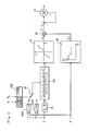
- Fig. 2 shows a block diagram of the control of the motor 10 by the controller 20.
- the output signal of the torque sensor 22 is input into a calculating part 41 via a low-pass filter 61 and a phase control element 62. Unnecessary high-frequency components are removed from the output signal of the torque sensor 22 by the low-pass filter 61.
- the phase of the output signal of the torque sensor 22 is controlled by the phase control element 62.
- the relationship between the steering torque T and the basic assist current i o is stored as an assist characteristic in the form of a table, calculation formula or the like, and the basic assist current i o corresponding to the detected steering torque T is calculated in the calculating part 41. For example, as shown in the calculating part 41 in Fig.
- the relationship between the steering torque T and the basic assist current i o is set so that the magnitude of the basic assist current i o increases as the magnitude of the steering torque T increases.
- the positive and negative signs of the steering torque T and basic assist current i o are reversed in the case of steering to the right and the case of steering to the left.
- the relationship between the vehicle speed V and vehicle speed gain G v is stored in the form of a table, calculation formula or the like, and the vehicle speed gain G v corresponding to the detected vehicle speed V is calculated in a calculating part 42.
- the relationship between the vehicle speed V and vehicle speed gain G v is set so that the vehicle speed gain G v is greater when the vehicle speed V is small than when the vehicle speed V is large.
- the product of the basic assist current i o and the basic vehicle speed gain G v corresponds to the basic assist torque T o .
- the magnitude of the basic assist torque T o increases and the assist gradient (dT o /dT) which is the rate of variation in the basic assist torque T o to the steering torque T increases with increase in the magnitude of the steering torque T.
- the basic assist torque T o varies according to the vehicle speed V.
- the relationship between the steering torque T and the basic assist torque T o is set so that the assist gradient varies in accordance with the variation in the detected steering torque T, and this set relationship is stored in the controller 20.
- the controller 20 determines the target driving current i* of the motor 10 by multiplying the basic assist current i o by the vehicle speed gain G v in a multiplying part 44, and controls the motor 10 by feedback control so that the deviation between the target driving current i* and the driving current i detected by the current sensor 26 is reduced. Specifically, the motor 10 is controlled so that the steering assist power is generated in accordance with the basic assist torque T o corresponding to the detected steering torque T.
- the phase control element 62 of the present embodiment functions as a phase lag compensator, the transfer function Gs of which is expressed by the following equation where s is a Laplace operator, t is a time constant, and a ( ⁇ 1) is a coefficient.
- G s ( 1 + a t s ) / ( 1 + t s )
- the phase control element 62 is selectively connected to a first coefficient setting element 64a and a second coefficient setting element 64b via a switch 63.
- the switch 63 is connected to a steering state judgment element 43g which judges whether the steering state is a return steering state in which the steering wheel 2 is steered in the direction toward the straight-forward steering position or a positive steering state in which the steering wheel 2 is steered in the direction away from the straight-forward steering position.
- the steering state judgment element 43g of the present embodiment compares the positive and negative signs of the steering torque T, which are reversed in the case of steering to the right and the case of steering to the left, with the positive and negative signs of the rate of variation in the steering angle ⁇ h , which are reversed when the steering wheel 2 is rotated to the clockwise direction and when the steering wheel 2 is rotated to the counterclockwise direction; in cases where both signs agree, the element 43g judges that the steering state is the positive steering state, while in cases where the two signs do not agree, the element 43g judges that the steering state is the return steering state. The element 43g then outputs a switching signal of the switch 63 in accordance with this judgment.
- the phase control element 62 When the switch 63 is switched in accordance with the judgment that the steering state is the positive steering state, the phase control element 62 is connected to the first coefficient setting element 64a so that the coefficient a in the transfer function Gs is set as a predetermined value ⁇ .
- the phase control element 62 When the switch 63 is switched in accordance the judgment that the steering state is the return steering state, the phase control element 62 is connected to the second coefficient setting element 64b so that the coefficient a in the transfer function Gs is set as a predetermined value ⁇ .
- the coefficients ⁇ and ⁇ in the present embodiment are constant, and 1 > ⁇ > ⁇ . Specifically, the coefficient a in the return steering state is smaller than that in the positive steering state.
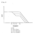
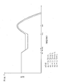
- Fig. 4 shows the frequency response characteristic of the output to input of the torque sensor 22 in the first embodiment.
- the horizontal axis indicates the frequency of the output signal of the torque sensor 22, and the vertical axis indicates the gain of the output to input of the torque sensor 22.
- the phase control characteristic of the phase control element 62 are altered in accordance with the judgment result obtained by the steering state judgment element 43g.
- the phase of the output signal of the torque sensor 22 is caused to vary by the phase control element 62, the gain in the higher frequency band in the frequency response characteristic of the output to input of the torque sensor 22 is reduced in the return steering state in comparison to the positive steering state.
- the breakpoint frequency ⁇ 3 in the return steering state is set by the phase control element 62 so that this frequency is greater than the breakpoint frequency ⁇ 2 in the positive steering state. Accordingly, in the higher frequency band where the frequency is greater than the set frequency, the gain of the output to input of the torque sensor 22 can be reduced to a lower value in the return steering state than in the positive steering state. As a result, even if the steering torque T acting in the positive steering direction abruptly decreases during the return steering; the abrupt decrease in the basic assist torque To corresponding to the detection value of the steering torque T detected by the torque sensor 22 can be suppressed. Accordingly, there is no abrupt variation in the steering assist power acting in the positive steering direction during the return steering, so that the convergence of the steering wheel 2 can be improved.
- Figs. 5 through 7 relate to a second embodiment. Parts which are similar to those of the first embodiment are labeled with the same symbols, and points of difference are described below.
- the phase control element 162 of the present embodiment functions as a phase lead lag compensator.
- the transfer function Gs is expressed by the following equation, where s is a Laplace operator, t 1 and t 2 are time constants, a 1 and a 2 are coefficients, t 1 > t2, a 1 ⁇ 1, and a 2 ⁇ 1.
- G s ⁇ ( 1 + a 1 t 1 s ) ( 1 + a 2 t 2 s ) ⁇ / ⁇ ( 1 + t 1 s ) ( 1 + t 2 s ) ⁇
- the coefficient a 1 in the transfer function Gs is set as ⁇
- the coefficient a 1 in the transfer function Gs is set as ⁇
- the assist gradient R corresponding to the detected steering torque T is determined by the coefficient setting elements 164a and 164b, and the phase control characteristic of the phase control element 162 is altered in accordance with the determined assist gradient R.
- the gain in the higher frequency band in the frequency response characteristic of the output to input of the torque sensor 22 is reduced in the positive steering state after the increase in the assist gradient R in comparison to the gain before this increase.
- the remaining construction is the same as in the first embodiment.
- Fig. 7 shows the frequency response characteristic of the output to input of the torque sensor 22 in the second embodiment.
- the characteristic in the positive steering state in which the coefficient a 1 is set as ⁇ is indicated by a solid line
- the phase control characteristic of the phase control element 162 is altered in accordance with the judgment result of the steering state judgment element 43g and the assist gradient R.
- the breakpoint frequency ⁇ 3 in the return steering state is set by the phase control element 162 so that this frequency is greater than the breakpoint frequency ⁇ 2 in the positive steering state. Accordingly, the gain of the output to input of the torque sensor 22 in the higher frequency band in the return steering state can be reduced to a lower value than in the positive steering state. Furthermore, when the assist gradient R increases in the positive steering state, the phase margin in the open loop characteristic of the output to input of the torque sensor 22 is increased so that the stability of control can be improved. Moreover, the system can also be devised so that the coefficient a 1 in the return steering state decreases if the assist gradient R increases.
- the phase control element in the abovementioned embodiments functions as a phase lag compensator or a phase lead lag compensator.
- the present invention is not limited to this.
- the mechanism for transmitting the rotation of the steering wheel to the vehicle wheels so that the steering angle varies is not limited to the mechanism described in the embodiments; it would also be possible to use a mechanism in which the rotation of the steering wheel is transmitted from the steering shaft to the vehicle wheels via a link mechanism other than a rack and pinion.
- this transfer mechanism is not limited to the mechanism shown in the embodiments.
- the steering assist power can also be applied by using the output of the motor to drive a ball nut engaged with a ball screw integrated with the rack.
Abstract
Description
- The present invention relates to an electric power steering apparatus which provides a steering assist power by means of a motor.
- In an electric power steering apparatus, a method is used in which the relationship between the steering torque and basic assist torque is stored as assist characteristics, and a motor for generating steering assist power is controlled so that steering assist power is generated in accordance with basic assist torque which corresponds to the steering torque detected by a torque sensor. In the control of the motor, when the deviation between the target value of the motor driving current and the detection value of the motor driving current detected by a current sensor is reduced, the cut-off frequency of a low-pass filter through which the detection signal of the motor driving current passes is set to a larger value in a return steering state in which the steering wheel is steered in the direction toward a straight-forward steering position than in a positive steering state in which the steering wheel is steered in the direction away from the straight-forward steering position. In this way, it is intended that even in a state where the motor generates counter electromotive force as a result of the driver's hands being removed from the steering wheel or the like during the return steering, the high-frequency components of the counter electromotive force are reflected in the control so that the motor driving current can be caused to converge on the target value stably (see
Japanese Unexamined Patent Publication No. 1996-20350 - However, when the steering torque decreases abruptly as a result of the driver's hands being removed from the steering wheel or the like during the return steering, the steering assist power which acts in the positive steering direction also decreases abruptly. Accordingly, the following problem arises, that is, the return of the steering wheel to the straight-forward position becomes abrupt, and the convergence of the motion of the steering wheel deteriorates. It is an object of the present invention to provide an electric power steering apparatus that can solve such problems.
- The feature of the present invention is that the electric power steering apparatus comprises a motor for generating steering assist power, a torque sensor for detecting steering torque, means for storing a relationship between steering torque and basic assist torque, means for controlling the motor so that the steering assist power is generated in accordance with the basic assist torque corresponding to the steering torque detected by the torque sensor, a phase control element for the output signal of the torque sensor, and a steering state judgment element for judging whether the steering state is a return steering state in which a steering wheel is steered in the direction toward a straight-forward steering position or a positive steering state in which the steering wheel is steered in the direction away from the straight-forward steering position, wherein the phase control characteristic of the phase control element is altered in accordance with the judgment result of the steering state judgment element so that the gain in the higher frequency band in the frequency response characteristic of the output to input of the torque sensor is reduced in the return steering state in comparison to the positive steering state.
- In the present invention, when the phase of the output signal of the torque sensor is altered by the phase control element, the gain in the higher frequency band in the frequency response characteristic of the output to input of the torque sensor is reduced in the return steering state in comparison to the positive steering state. As a result, even if the steering torque acting in the positive steering direction abruptly decreases during the return steering, the abrupt decrease in the basic assist torque corresponding to the detection value of the steering torque detected by the torque sensor can be suppressed. Accordingly, there is no abrupt variation in the steering assist power acting in the positive steering direction during the return steering, and the convergence of the steering wheel is improved.
- It is desirable that the relationship between the steering torque and the basic assist torque is set so that assist gradient which is the rate of variation in the basic assist torque to the steering torque varies in accordance with the variation in the detected steering torque, that means for determining the assist gradient corresponding to the detected steering torque is provided, and that the phase control characteristic of the phase control element is altered in accordance with the assist gradient in at least the positive steering state so that the gain in the higher frequency band in the frequency response characteristic of the output to input of the torque sensor is reduced after the increase in the assist gradient in comparison to the gain before this increase.
- As a result, when the assist gradient increases in the positive steering state, the phase margin in the open loop characteristic of the output to input of the torque sensor is increased, so that the stability of control can be improved.
- According to the electric power steering apparatus of the present invention, the convergence of the steering wheel during the return steering can be improved, and the stability of control can be improved during the positive steering.
-
- Fig. 1 is a structural explanatory diagram of a first embodiment of the electric power steering apparatus of the present invention.
- Fig. 2 is a control block diagram of the first embodiment of the electric power steering apparatus of the present invention.
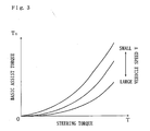
- Fig. 3 is a graph showing the relationship between the steering torque, basic assist torque and vehicle speed in the embodiments of the electric power steering apparatus of the present invention.
- Fig. 4 is a graph showing the frequency response characteristic of the output to input of the torque sensor in the first embodiment of the electric power steering apparatus of the present invention.
- Fig. 5 is a control block diagram of a second embodiment of the electric power steering apparatus of the present invention.
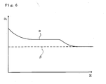
- Fig. 6 is a graph showing the relationship between the assist gradient and the coefficients in the phase control element in the second embodiment of the electric power steering apparatus of the present invention.
- Fig. 7 is a graph showing the frequency response characteristic of the output to input of the torque sensor in the second embodiment of the electric power steering apparatus of the present invention.
- The vehicle electric
power steering apparatus 1 of the first embodiment shown in Fig. 1 comprises a mechanism for transmitting the rotation of thesteering wheel 2 caused by steering operation to thevehicle wheels 3 so that the steering angle varies. In the present embodiment, the rotation of thesteering wheel 2 is transmitted to apinion 5 via a steering shaft 4, so that arack 6 which engages with thepinion 5 is caused to move, and the movement of thisrack 6 is transmitted to thevehicle wheels 3 viatie rods 7 andknuckle arms 8 so that the steering angle varies. - A
motor 10 is provided to generate steering assist power which acts on the line via which the rotation of thesteering wheel 2 is transmitted to thevehicle wheels 3. In the present embodiment, the rotation of the output shaft of themotor 10 is transmitted to the steering shaft 4 via a speedreduction gear mechanism 11, so that the steering assist power is applied. - The
motor 10 is connected to acontroller 20 constructed from a computer via adriving circuit 21. Atorque sensor 22 which detects the steering torque T of thesteering wheel 2, asteering angle sensor 23 which detects the steering angle θh which corresponds to the rotational angle of thesteering wheel 2, avehicle speed sensor 24 which detects the vehicle speed V, and acurrent sensor 26 which detects the driving current i of themotor 10 are connected to thecontroller 20. - Fig. 2 shows a block diagram of the control of the
motor 10 by thecontroller 20. - The output signal of the
torque sensor 22 is input into a calculatingpart 41 via a low-pass filter 61 and aphase control element 62. Unnecessary high-frequency components are removed from the output signal of thetorque sensor 22 by the low-pass filter 61. The phase of the output signal of thetorque sensor 22 is controlled by thephase control element 62. For example, the relationship between the steering torque T and the basic assist current io is stored as an assist characteristic in the form of a table, calculation formula or the like, and the basic assist current io corresponding to the detected steering torque T is calculated in the calculatingpart 41. For example, as shown in the calculatingpart 41 in Fig. 2, the relationship between the steering torque T and the basic assist current io is set so that the magnitude of the basic assist current io increases as the magnitude of the steering torque T increases. The positive and negative signs of the steering torque T and basic assist current io are reversed in the case of steering to the right and the case of steering to the left. - The relationship between the vehicle speed V and vehicle speed gain Gv is stored in the form of a table, calculation formula or the like, and the vehicle speed gain Gv corresponding to the detected vehicle speed V is calculated in a calculating
part 42. For example, as shown in the calculatingpart 42 in Fig. 2, the relationship between the vehicle speed V and vehicle speed gain Gv is set so that the vehicle speed gain Gv is greater when the vehicle speed V is small than when the vehicle speed V is large. - The product of the basic assist current io and the basic vehicle speed gain Gv corresponds to the basic assist torque To. For example, as shown in Fig. 3, when the vehicle speed V is constant, the magnitude of the basic assist torque To increases and the assist gradient (dTo/dT) which is the rate of variation in the basic assist torque To to the steering torque T increases with increase in the magnitude of the steering torque T. Furthermore, the basic assist torque To varies according to the vehicle speed V. When the steering torque T is constant, the basic assist torque To increases and the assist gradient increases with decrease in the vehicle speed V. Specifically, the relationship between the steering torque T and the basic assist torque To is set so that the assist gradient varies in accordance with the variation in the detected steering torque T, and this set relationship is stored in the
controller 20. - The
controller 20 determines the target driving current i* of themotor 10 by multiplying the basic assist current io by the vehicle speed gain Gv in amultiplying part 44, and controls themotor 10 by feedback control so that the deviation between the target driving current i* and the driving current i detected by thecurrent sensor 26 is reduced. Specifically, themotor 10 is controlled so that the steering assist power is generated in accordance with the basic assist torque To corresponding to the detected steering torque T. - The
phase control element 62 of the present embodiment functions as a phase lag compensator, the transfer function Gs of which is expressed by the following equation where s is a Laplace operator, t is a time constant, and a (< 1) is a coefficient.
- The
phase control element 62 is selectively connected to a firstcoefficient setting element 64a and a secondcoefficient setting element 64b via aswitch 63. Theswitch 63 is connected to a steeringstate judgment element 43g which judges whether the steering state is a return steering state in which thesteering wheel 2 is steered in the direction toward the straight-forward steering position or a positive steering state in which thesteering wheel 2 is steered in the direction away from the straight-forward steering position. The steeringstate judgment element 43g of the present embodiment compares the positive and negative signs of the steering torque T, which are reversed in the case of steering to the right and the case of steering to the left, with the positive and negative signs of the rate of variation in the steering angle θh, which are reversed when thesteering wheel 2 is rotated to the clockwise direction and when thesteering wheel 2 is rotated to the counterclockwise direction; in cases where both signs agree, theelement 43g judges that the steering state is the positive steering state, while in cases where the two signs do not agree, theelement 43g judges that the steering state is the return steering state. Theelement 43g then outputs a switching signal of theswitch 63 in accordance with this judgment. - When the
switch 63 is switched in accordance with the judgment that the steering state is the positive steering state, thephase control element 62 is connected to the firstcoefficient setting element 64a so that the coefficient a in the transfer function Gs is set as a predetermined value α. When theswitch 63 is switched in accordance the judgment that the steering state is the return steering state, thephase control element 62 is connected to the secondcoefficient setting element 64b so that the coefficient a in the transfer function Gs is set as a predetermined value β. The coefficients α and β in the present embodiment are constant, and 1 > α > β. Specifically, the coefficient a in the return steering state is smaller than that in the positive steering state. - Fig. 4 shows the frequency response characteristic of the output to input of the
torque sensor 22 in the first embodiment. The horizontal axis indicates the frequency of the output signal of thetorque sensor 22, and the vertical axis indicates the gain of the output to input of thetorque sensor 22. In Fig. 4, the characteristic in a case where the phase of the signal is not lagged by thephase control element 62 are indicated by a solid line, the characteristic in the positive steering state in which the coefficient a is set as α are indicated by a broken line, the characteristic in the return steering state in which the coefficient a is set as β are indicated by a one-dot chain line, ω1 = 1/(2πt), ω2 = 1/(2παt), ω3 = 1/(2πβt), and ωc indicates the cut-off frequency of the low-pass filter 61. Specifically, the phase control characteristic of thephase control element 62 are altered in accordance with the judgment result obtained by the steeringstate judgment element 43g. As a result, since the phase of the output signal of thetorque sensor 22 is caused to vary by thephase control element 62, the gain in the higher frequency band in the frequency response characteristic of the output to input of thetorque sensor 22 is reduced in the return steering state in comparison to the positive steering state. - In the abovementioned first embodiment, the breakpoint frequency ω3 in the return steering state is set by the
phase control element 62 so that this frequency is greater than the breakpoint frequency ω2 in the positive steering state. Accordingly, in the higher frequency band where the frequency is greater than the set frequency, the gain of the output to input of thetorque sensor 22 can be reduced to a lower value in the return steering state than in the positive steering state. As a result, even if the steering torque T acting in the positive steering direction abruptly decreases during the return steering; the abrupt decrease in the basic assist torque To corresponding to the detection value of the steering torque T detected by thetorque sensor 22 can be suppressed. Accordingly, there is no abrupt variation in the steering assist power acting in the positive steering direction during the return steering, so that the convergence of thesteering wheel 2 can be improved. - Figs. 5 through 7 relate to a second embodiment. Parts which are similar to those of the first embodiment are labeled with the same symbols, and points of difference are described below. The
phase control element 162 of the present embodiment functions as a phase lead lag compensator. The transfer function Gs is expressed by the following equation, where s is a Laplace operator, t1 and t2 are time constants, a1 and a2 are coefficients, t1 > t2, a1 ≤ 1, and a2 ≥ 1.
- When the
phase control element 162 is connected to the firstcoefficient setting element 164a via theswitch 63 in the positive steering state, the coefficient a1 in the transfer function Gs is set as α, and when thephase control element 162 is connected to the secondcoefficient setting element 164b via theswitch 63 in the return driving state, the coefficient a1 in the transfer function Gs is set as β. As shown in Fig. 6, the coefficient a1 in the present embodiment is set as a function of the assist gradient R = dTo/dT, which is the rate of variation in the basic assist torque To to the steering torque T, the coefficient a1 (= α) in the positive steering state decreases with an increase in the assist gradient R, the coefficient a1 (= β) in the return steering state is set as a constant value which shows no variation even if the assist gradient R varies, and α ≥ β. Specifically, the assist gradient R corresponding to the detected steering torque T is determined by thecoefficient setting elements phase control element 162 is altered in accordance with the determined assist gradient R. As a result, the gain in the higher frequency band in the frequency response characteristic of the output to input of thetorque sensor 22 is reduced in the positive steering state after the increase in the assist gradient R in comparison to the gain before this increase. The remaining construction is the same as in the first embodiment. - Fig. 7 shows the frequency response characteristic of the output to input of the
torque sensor 22 in the second embodiment. The characteristic in the positive steering state in which the coefficient a1 is set as α is indicated by a solid line, the characteristics in the return steering state in which the coefficient a1 is set as β is indicated by a broken line, ω1 = 1/(2πt1), ω2 = 1/(2παt1), ω3 = 1/(2πβt1), ω4 = 1/(2πa2t2), and ω5 = 1/(2πt2). Specifically, the phase control characteristic of thephase control element 162 is altered in accordance with the judgment result of the steeringstate judgment element 43g and the assist gradient R. As a result, the breakpoint frequency ω3 in the return steering state is set by thephase control element 162 so that this frequency is greater than the breakpoint frequency ω2 in the positive steering state. Accordingly, the gain of the output to input of thetorque sensor 22 in the higher frequency band in the return steering state can be reduced to a lower value than in the positive steering state. Furthermore, when the assist gradient R increases in the positive steering state, the phase margin in the open loop characteristic of the output to input of thetorque sensor 22 is increased so that the stability of control can be improved. Moreover, the system can also be devised so that the coefficient a1 in the return steering state decreases if the assist gradient R increases. - The present invention is not limited to the abovementioned embodiments. For example, the phase control element in the abovementioned embodiments functions as a phase lag compensator or a phase lead lag compensator. However, the present invention is not limited to this. For example, the phase control element can also function as a phase lead compensator, in which the coefficient a (> 1) in the transfer function Gs = (1 + ats)/(1 +ts) of the phase lead compensator is reduced in the return steering state in comparison to the positive steering state. Furthermore, the mechanism for transmitting the rotation of the steering wheel to the vehicle wheels so that the steering angle varies is not limited to the mechanism described in the embodiments; it would also be possible to use a mechanism in which the rotation of the steering wheel is transmitted from the steering shaft to the vehicle wheels via a link mechanism other than a rack and pinion. Furthermore, as long as the transfer mechanism which transmits the output of the motor for generating the steering assist power to the steering system is capable of applying steering assist power, this transfer mechanism is not limited to the mechanism shown in the embodiments. For example, the steering assist power can also be applied by using the output of the motor to drive a ball nut engaged with a ball screw integrated with the rack.
Claims (2)
- An electric power steering apparatus comprising:a motor (10) for generating steering assist power;a torque sensor (22) for detecting steering torque:means (20) for storing a relationship between steering torque and basic assist torque;means (20) for controlling said motor (10) so that the steering assist power is generated in accordance with the basic assist torque corresponding to the steering torque detected by the torque sensor (22);a phase control element (62, 162) for the output signal of said torque sensor (22); anda steering state judgment element (43g) for judging whether the steering state is a return steering state in which a steering wheel (2) is steered in the direction toward a straight-forward steering position or a positive steering state in which the steering wheel (2) is steered in the direction away from the straight-forward steering position;wherein the phase control characteristic of said phase control element (62, 162) is altered in accordance with the judgment result of said steering state judgment element (43g) so that the gain in the higher frequency band in the frequency response characteristic of the output to input of said torque sensor (22) is reduced in the return steering state in comparison to the positive steering state.
- The electric power steering apparatus according to claim 1, wherein the relationship between the steering torque and the basic assist torque is set so that assist gradient which is the rate of variation in the basic assist torque to the steering torque varies in accordance with the variation in the detected steering torque,
means (164a, 164b) for determining the assist gradient corresponding to the detected steering torque is provided, and
the phase control characteristic of said phase control element (62, 162) is altered in accordance with the assist gradient in at least the positive steering state so that the gain in the higher frequency band in the frequency response characteristic of the output to input of said torque sensor (22) is reduced after the increase in the assist gradient in comparison to the gain before this increase.
Applications Claiming Priority (1)
| Application Number | Priority Date | Filing Date | Title |
|---|---|---|---|
| JP2005119652A JP4573038B2 (en) | 2005-04-18 | 2005-04-18 | Electric power steering device |
Publications (3)
| Publication Number | Publication Date |
|---|---|
| EP1714852A2 true EP1714852A2 (en) | 2006-10-25 |
| EP1714852A3 EP1714852A3 (en) | 2007-01-24 |
| EP1714852B1 EP1714852B1 (en) | 2014-03-26 |
Family
ID=36698704
Family Applications (1)
| Application Number | Title | Priority Date | Filing Date |
|---|---|---|---|
| EP06007869.8A Expired - Fee Related EP1714852B1 (en) | 2005-04-18 | 2006-04-13 | Electric power steering apparatus |
Country Status (3)
| Country | Link |
|---|---|
| US (1) | US7503421B2 (en) |
| EP (1) | EP1714852B1 (en) |
| JP (1) | JP4573038B2 (en) |
Cited By (1)
| Publication number | Priority date | Publication date | Assignee | Title |
|---|---|---|---|---|
| WO2016203171A1 (en) * | 2015-06-19 | 2016-12-22 | Jtekt Europe | Use of a phase-lead filter to separate the manual steering setting from the power steering control stability setting |
Families Citing this family (6)
| Publication number | Priority date | Publication date | Assignee | Title |
|---|---|---|---|---|
| JP2005082034A (en) * | 2003-09-09 | 2005-03-31 | Koyo Seiko Co Ltd | Electric power steering system |
| JP5194716B2 (en) * | 2007-10-30 | 2013-05-08 | 株式会社ジェイテクト | Electric power steering device |
| JP4606476B2 (en) * | 2008-04-08 | 2011-01-05 | 三菱電機株式会社 | Electric power steering control device |
| JP4948567B2 (en) * | 2009-05-29 | 2012-06-06 | 三菱電機株式会社 | Vehicle steering system |
| KR101767878B1 (en) * | 2011-07-22 | 2017-08-30 | 현대모비스 주식회사 | Steering control device of motor driven powersteering system |
| KR20130090987A (en) * | 2012-02-07 | 2013-08-16 | 주식회사 만도 | Electric power steering apparatus and controlling method thereof |
Citations (3)
| Publication number | Priority date | Publication date | Assignee | Title |
|---|---|---|---|---|
| EP0737611A2 (en) | 1995-04-10 | 1996-10-16 | Mitsubishi Denki Kabushiki Kaisha | Control system for electrically operated power steering apparatus |
| WO2005026003A1 (en) | 2003-09-09 | 2005-03-24 | Koyo Seiko Co., Ltd. | Electric power steering system |
| WO2006051786A1 (en) | 2004-11-09 | 2006-05-18 | Jtekt Corporation | Electric power steering device |
Family Cites Families (8)
| Publication number | Priority date | Publication date | Assignee | Title |
|---|---|---|---|---|
| JPH0820350A (en) * | 1994-07-05 | 1996-01-23 | Honda Motor Co Ltd | Electric power steering device |
| JPH0891236A (en) * | 1994-09-21 | 1996-04-09 | Honda Motor Co Ltd | Motor driven power steering device |
| JP2001088726A (en) * | 1999-09-20 | 2001-04-03 | Suzuki Motor Corp | Controlling method for electric power steering |
| JP3780823B2 (en) * | 2000-05-25 | 2006-05-31 | 日本精工株式会社 | Control device for electric power steering device |
| JP3551147B2 (en) * | 2000-11-17 | 2004-08-04 | 日本精工株式会社 | Control device for electric power steering device |
| JP3891258B2 (en) * | 2001-07-10 | 2007-03-14 | 株式会社ジェイテクト | Electric power steering device |
| JP3856690B2 (en) * | 2001-11-30 | 2006-12-13 | 株式会社ジェイテクト | Electric power steering device |
| JP4193113B2 (en) * | 2003-02-27 | 2008-12-10 | 株式会社ジェイテクト | Electric power steering device |
-
2005
- 2005-04-18 JP JP2005119652A patent/JP4573038B2/en not_active Expired - Fee Related
-
2006
- 2006-04-13 EP EP06007869.8A patent/EP1714852B1/en not_active Expired - Fee Related
- 2006-04-18 US US11/407,006 patent/US7503421B2/en active Active
Patent Citations (3)
| Publication number | Priority date | Publication date | Assignee | Title |
|---|---|---|---|---|
| EP0737611A2 (en) | 1995-04-10 | 1996-10-16 | Mitsubishi Denki Kabushiki Kaisha | Control system for electrically operated power steering apparatus |
| WO2005026003A1 (en) | 2003-09-09 | 2005-03-24 | Koyo Seiko Co., Ltd. | Electric power steering system |
| WO2006051786A1 (en) | 2004-11-09 | 2006-05-18 | Jtekt Corporation | Electric power steering device |
Cited By (5)
| Publication number | Priority date | Publication date | Assignee | Title |
|---|---|---|---|---|
| WO2016203171A1 (en) * | 2015-06-19 | 2016-12-22 | Jtekt Europe | Use of a phase-lead filter to separate the manual steering setting from the power steering control stability setting |
| FR3037671A1 (en) * | 2015-06-19 | 2016-12-23 | Jtekt Europe Sas | USING A PHASE ADVANCE FILTER TO SEPARATE THE SPRING ADJUSTMENT FROM THE STEERING WHEEL ADJUSTING THE STABILITY OF AN ASSISTED STEERING CONTROL |
| CN107771146A (en) * | 2015-06-19 | 2018-03-06 | 捷太格特欧洲公司 | Set using phase lead filter to separate manual steering from the setting of power course changing control stability |
| CN107771146B (en) * | 2015-06-19 | 2020-07-31 | 捷太格特欧洲公司 | Using a phase lead filter to separate manual steering settings from power steering control stability settings |
| US10889319B2 (en) | 2015-06-19 | 2021-01-12 | Jtekt Europe | Use of a phase-lead filter to separate the manual steering setting from the power steering control stability setting |
Also Published As
| Publication number | Publication date |
|---|---|
| US20060231325A1 (en) | 2006-10-19 |
| JP2006298040A (en) | 2006-11-02 |
| US7503421B2 (en) | 2009-03-17 |
| JP4573038B2 (en) | 2010-11-04 |
| EP1714852A3 (en) | 2007-01-24 |
| EP1714852B1 (en) | 2014-03-26 |
Similar Documents
| Publication | Publication Date | Title |
|---|---|---|
| EP1767433B1 (en) | Electric power steering apparatus | |
| US9446789B2 (en) | Electric power steering apparatus | |
| EP2942264B1 (en) | Electric power steering device | |
| EP1984229B1 (en) | Electric power steering device, and control method thereof | |
| US7530423B2 (en) | Vehicular variable steering ratio control device and control method thereof | |
| JP5050421B2 (en) | Control device for electric power steering device | |
| US8272474B2 (en) | Electric power steering system | |
| EP1262394B1 (en) | Soft-disable damping for electric power steering | |
| EP1808358B1 (en) | Electric power steering apparatus | |
| WO2016174829A1 (en) | Electric power steering control apparatus | |
| EP1714852A2 (en) | Electric power steering apparatus | |
| US20080315809A1 (en) | Motor controller and electric power steering apparatus | |
| US11685429B2 (en) | Steering control device | |
| US11919581B2 (en) | Steering control device | |
| EP2639137B1 (en) | Vehicle steering control system | |
| JP2000185660A (en) | Control device for electric power steering device | |
| EP3971062A1 (en) | Steering control device | |
| JP5233215B2 (en) | Electric power steering device | |
| JP4333399B2 (en) | Vehicle steering device | |
| JP5181540B2 (en) | Electric power steering device | |
| JP2008132918A (en) | Control unit of vehicular electric power steering device | |
| JP4759978B2 (en) | Control device for electric power steering device | |
| US20230016560A1 (en) | Control device and electric power steering device | |
| JPH08107696A (en) | Controller for power steering | |
| JP2007261344A (en) | Electric power steering device |
Legal Events
| Date | Code | Title | Description |
|---|---|---|---|
| PUAI | Public reference made under article 153(3) epc to a published international application that has entered the european phase |
Free format text: ORIGINAL CODE: 0009012 |
|
| AK | Designated contracting states |
Kind code of ref document: A2 Designated state(s): AT BE BG CH CY CZ DE DK EE ES FI FR GB GR HU IE IS IT LI LT LU LV MC NL PL PT RO SE SI SK TR |
|
| AX | Request for extension of the european patent |
Extension state: AL BA HR MK YU |
|
| PUAL | Search report despatched |
Free format text: ORIGINAL CODE: 0009013 |
|
| AK | Designated contracting states |
Kind code of ref document: A3 Designated state(s): AT BE BG CH CY CZ DE DK EE ES FI FR GB GR HU IE IS IT LI LT LU LV MC NL PL PT RO SE SI SK TR |
|
| AX | Request for extension of the european patent |
Extension state: AL BA HR MK YU |
|
| 17P | Request for examination filed |
Effective date: 20070720 |
|
| AKX | Designation fees paid |
Designated state(s): DE FR GB |
|
| 17Q | First examination report despatched |
Effective date: 20110104 |
|
| GRAP | Despatch of communication of intention to grant a patent |
Free format text: ORIGINAL CODE: EPIDOSNIGR1 |
|
| INTG | Intention to grant announced |
Effective date: 20130912 |
|
| GRAS | Grant fee paid |
Free format text: ORIGINAL CODE: EPIDOSNIGR3 |
|
| GRAP | Despatch of communication of intention to grant a patent |
Free format text: ORIGINAL CODE: EPIDOSNIGR1 |
|
| INTG | Intention to grant announced |
Effective date: 20140124 |
|
| GRAA | (expected) grant |
Free format text: ORIGINAL CODE: 0009210 |
|
| AK | Designated contracting states |
Kind code of ref document: B1 Designated state(s): DE FR GB |
|
| REG | Reference to a national code |
Ref country code: GB Ref legal event code: FG4D |
|
| REG | Reference to a national code |
Ref country code: DE Ref legal event code: R096 Ref document number: 602006040801 Country of ref document: DE Effective date: 20140508 |
|
| REG | Reference to a national code |
Ref country code: DE Ref legal event code: R097 Ref document number: 602006040801 Country of ref document: DE |
|
| PLBE | No opposition filed within time limit |
Free format text: ORIGINAL CODE: 0009261 |
|
| STAA | Information on the status of an ep patent application or granted ep patent |
Free format text: STATUS: NO OPPOSITION FILED WITHIN TIME LIMIT |
|
| GBPC | Gb: european patent ceased through non-payment of renewal fee |
Effective date: 20140626 |
|
| 26N | No opposition filed |
Effective date: 20150106 |
|
| REG | Reference to a national code |
Ref country code: DE Ref legal event code: R097 Ref document number: 602006040801 Country of ref document: DE Effective date: 20150106 |
|
| PG25 | Lapsed in a contracting state [announced via postgrant information from national office to epo] |
Ref country code: GB Free format text: LAPSE BECAUSE OF NON-PAYMENT OF DUE FEES Effective date: 20140626 |
|
| REG | Reference to a national code |
Ref country code: FR Ref legal event code: PLFP Year of fee payment: 11 |
|
| REG | Reference to a national code |
Ref country code: FR Ref legal event code: PLFP Year of fee payment: 12 |
|
| REG | Reference to a national code |
Ref country code: FR Ref legal event code: PLFP Year of fee payment: 13 |
|
| PGFP | Annual fee paid to national office [announced via postgrant information from national office to epo] |
Ref country code: FR Payment date: 20210309 Year of fee payment: 16 |
|
| PGFP | Annual fee paid to national office [announced via postgrant information from national office to epo] |
Ref country code: DE Payment date: 20210316 Year of fee payment: 16 |
|
| REG | Reference to a national code |
Ref country code: DE Ref legal event code: R119 Ref document number: 602006040801 Country of ref document: DE |
|
| PG25 | Lapsed in a contracting state [announced via postgrant information from national office to epo] |
Ref country code: FR Free format text: LAPSE BECAUSE OF NON-PAYMENT OF DUE FEES Effective date: 20220430 Ref country code: DE Free format text: LAPSE BECAUSE OF NON-PAYMENT OF DUE FEES Effective date: 20221103 |