EP1714596B1 - Dispositif de distribution d'une matière en poudre, en particulier de boissons liophilisées - Google Patents
Dispositif de distribution d'une matière en poudre, en particulier de boissons liophilisées Download PDFInfo
- Publication number
- EP1714596B1 EP1714596B1 EP05103178A EP05103178A EP1714596B1 EP 1714596 B1 EP1714596 B1 EP 1714596B1 EP 05103178 A EP05103178 A EP 05103178A EP 05103178 A EP05103178 A EP 05103178A EP 1714596 B1 EP1714596 B1 EP 1714596B1
- Authority
- EP
- European Patent Office
- Prior art keywords
- base plate
- base unit
- base
- cartridge
- drawer
- Prior art date
- Legal status (The legal status is an assumption and is not a legal conclusion. Google has not performed a legal analysis and makes no representation as to the accuracy of the status listed.)
- Expired - Lifetime
Links
- 239000000843 powder Substances 0.000 title description 3
- 239000000463 material Substances 0.000 title description 2
- 239000011236 particulate material Substances 0.000 claims description 14
- NJPPVKZQTLUDBO-UHFFFAOYSA-N novaluron Chemical compound C1=C(Cl)C(OC(F)(F)C(OC(F)(F)F)F)=CC=C1NC(=O)NC(=O)C1=C(F)C=CC=C1F NJPPVKZQTLUDBO-UHFFFAOYSA-N 0.000 claims description 10
- PEDCQBHIVMGVHV-UHFFFAOYSA-N Glycerine Chemical compound OCC(O)CO PEDCQBHIVMGVHV-UHFFFAOYSA-N 0.000 claims description 3
- 239000013618 particulate matter Substances 0.000 abstract description 18
- 238000012423 maintenance Methods 0.000 abstract description 2
- 230000000694 effects Effects 0.000 description 10
- 235000013361 beverage Nutrition 0.000 description 7
- 238000003780 insertion Methods 0.000 description 4
- 230000037431 insertion Effects 0.000 description 4
- 230000002776 aggregation Effects 0.000 description 3
- 238000013019 agitation Methods 0.000 description 3
- 238000004220 aggregation Methods 0.000 description 2
- 230000005484 gravity Effects 0.000 description 2
- 239000003550 marker Substances 0.000 description 2
- 230000035515 penetration Effects 0.000 description 2
- XLYOFNOQVPJJNP-UHFFFAOYSA-N water Substances O XLYOFNOQVPJJNP-UHFFFAOYSA-N 0.000 description 2
- 241001122767 Theaceae Species 0.000 description 1
- 238000005054 agglomeration Methods 0.000 description 1
- 238000012550 audit Methods 0.000 description 1
- 230000000903 blocking effect Effects 0.000 description 1
- 230000003247 decreasing effect Effects 0.000 description 1
- 235000013312 flour Nutrition 0.000 description 1
- 239000012530 fluid Substances 0.000 description 1
- 239000011521 glass Substances 0.000 description 1
- 239000008187 granular material Substances 0.000 description 1
- 238000012986 modification Methods 0.000 description 1
- 230000004048 modification Effects 0.000 description 1
- 238000007790 scraping Methods 0.000 description 1
- 239000000344 soap Substances 0.000 description 1
- 235000014347 soups Nutrition 0.000 description 1
- 235000013599 spices Nutrition 0.000 description 1
- 235000000346 sugar Nutrition 0.000 description 1
- 229940034610 toothpaste Drugs 0.000 description 1
- 239000000606 toothpaste Substances 0.000 description 1
Images


Classifications
-
- A—HUMAN NECESSITIES
- A47—FURNITURE; DOMESTIC ARTICLES OR APPLIANCES; COFFEE MILLS; SPICE MILLS; SUCTION CLEANERS IN GENERAL
- A47J—KITCHEN EQUIPMENT; COFFEE MILLS; SPICE MILLS; APPARATUS FOR MAKING BEVERAGES
- A47J47/00—Kitchen containers, stands or the like, not provided for in other groups of this subclass; Cutting-boards, e.g. for bread
- A47J47/01—Kitchen containers, stands or the like, not provided for in other groups of this subclass; Cutting-boards, e.g. for bread with dispensing devices
Definitions
- the present invention furthermore relates to a device for dispensing particulate matter, in particular lyophilized beverage, comprising the abovementioned base unit.
- Such a basic unit and such a distribution device are known for example from the document US 3,393,838 which describes a dispensing device comprising a base unit in which a supply container is housed, provided with its drawer base.
- the drawer of said base also has an open position and a closed position.
- the basic unit of the patent US 3,393,838 further comprises a sliding drawer which comprises a fastening means for fixing the drawer of the base of the cartridge. Therefore, when the user pulls on the drawer of the base unit, it also opens the drawer of the cartridge since the drawer of the cartridge and the drawer of the base unit are fixed together. In the document US 3,393,838 it is the drawer that is movable and the product cartridge remains motionless in the base unit.
- this basic unit is not very convenient to use and has the disadvantage that the particulate product agglomerates in the supply container. Indeed, firstly, a traction movement is never an easy natural movement for a user and then the particulate product which is generally intended to be rapidly dissolved in water agglomerates in contact with the stagnant atmosphere. which reigns in the container and under the effect of its own weight.
- the object of the invention is to overcome the drawbacks of the state of the art by providing a simpler basic unit of use, in which the user will use particulate matter by a more natural and much easier movement. while solving the problem of agglomeration of particulate matter.
- the drawer is fixed to the first element and always remains in the same place, whether in the open position or in the closed position. It is the supply container that recoils relative to the drawer by the pressure exerted by the user who wants to use particulate matter.
- the first attachment means may also be on a front wall extending forward of the base unit, substantially vertically with respect to said base plate. The effect will be exactly the same.
- the first fastening means and the second fixing means may for example be chosen from fastening means consisting of at least one orifice and at least one protrusion provided for to be housed in the orifice, or at least one notch and at least one protrusion provided to be housed in the notch.
- the drawer reaches its open position when the user pushes on the supply container (particulate matter cartridge). Since the drawer is attached to the base unit, it is the recoil movement of the supply container imposed by the user that will control the opening of the drawer. It is clear that pushing on the supply container is a simpler and more natural gesture, even more ergonomic for the user. The fact that the drawer always remains in the same place, also allows the user to better target where the particulate matter will be distributed and better adjust the container that it will place for example below the opening to recover this subject. In the case of a freeze-dried beverage dispenser, the user will be able to better adjust his cup or glass, which will result in a cleaner device being used.
- the recoil movement of the cartridge allows agitation of the particulate matter and strongly limits its aggregation.
- the prevailing atmosphere is no longer a stagnant atmosphere and the product, which undergoes agitation with each use, no longer agglomerates either under the effect of its own weight.
- second rear wall is meant either a relatively flat surface or a rod-type cylinder or any similar means, connecting the third and fourth side walls.
- a substantially flat surface will be preferred as the back wall, which may be of any size. Indeed, a flat surface allows among other things a better maintenance of the side walls in place and the cartridge.
- the supply container belted in this way by the second element does not unbalance, the weight of the container is slightly increased by the presence of this second element which acts as a sheath, which improves its stability during the imposed movement.
- this second element which acts as a sheath, which improves its stability during the imposed movement.
- it is the second element that is recoiled. As it surrounds the supply container and its base, it imposes the recoil motion to the supply container, while the drawer is secured to the first element which is fixed thereto.
- the first element comprises at least a first translational means and said second element comprises at least one second translation means, reciprocal to the aforementioned first translation means.
- first translation means for guiding the second base plate of the second element
- second translation means located either on the side walls or on the base plate of the second element or the opposite or any similar alternative to guide the translation of the second element within the first element.
- the first element comprises at least one first pivot means and said second element comprises at least one second pivot means, reciprocal to the aforementioned first pivot means.
- the movement imposed by the user is a rotational movement which has the effect of ensuring better agitation of the product in the cartridge and further limits the aggregation of the latter.
- the movement is even more conducive to the penetration of the product in the opening of the drawer and the return rotation movement, which brings the container and the drawer in the closed position has a scraping effect which reduces the jamming of the product between the base and the drawer.
- pivot means for example a protuberance and an orifice, the orifice being located on one or both side walls of the first element, or on one or both side walls of the second element, the protuberances are respectively located respectively on one or on both side walls of the second element, or on one or both side walls of the first element.
- any similar pivot means can also be used, one can for example consider a curved groove which would guide a protuberance in a rotational movement, or even a groove comprising a first straight or inclined rectilinear section and an abutment arranged for guide any protuberance, which would result in an inclined translation movement or not, recoil and then a rotational movement when the contact with the protrusion abutment.
- the rear wall comprises guide means arranged to guide flanges provided on side edges of the base of the supply container.
- guide means for example a groove or a guide rail, arranged to receive the flanges of said base allow introduction of the cartridge into the second element easier. Guiding makes the insertion movement of the cartridge with its base more accurate.
- the first element comprises a first rear wall which comprises a first lower part and a second upper part which is curved and the second rear wall comprises a third lower part and a fourth part. upper part which is curved, the fourth upper part having a curvature similar to that of the second curved part of the first element.
- the curvature of the rear wall allows an even easier introduction of the cartridge.
- the movement of introduction of the cartridge by the user is as follows. The user has the cartridge in hand in an inclined manner, he places it against the rear face of the second element, and slides against this rear wall, until meeting the substantially vertical part, at this moment, naturally, he straightens the cartridge and it enters exactly into the cavity to be housed, with the position it must have.
- first and second rear walls are inclined instead of curved.
- the second rear wall of the second element comprises at least one row of openings, each opening being provided to receive a shim.
- the wedge makes it possible to limit the movement of the second element within the first element and therefore this results in limiting the mutual opening of the cartridge drawer to limit the amount of particulate product that is dispensed during the rotational movement.
- opening row could be on the first rear wall or on the first base plate according to the adopted embodiments (translational or rotational movement).
- the wedge may have a shape of U, L, I or crescent moon or any similar shape, preferably the wedge has an L shape.
- the L-shape allows to place two rows of staggered openings without that a second end of the hold prevents the introduction of the first end of the wedge into the hole.
- the L limits the penetration of the wedge into the hole and allows a better grip to the user.
- means for fixing to a support are provided.
- the invention also relates to a device for dispensing particulate material, in particular freeze-dried beverage comprising the aforesaid base unit.
- Figure 1 is a sectional side view of the first element of the base unit according to the invention.
- FIG. 2 is a perspective view illustrating the second element according to the invention, in which the row can be seen of orifices for blocking the relative movement of the two inner and outer elements relative to each other.
- Fig. 3 is a perspective view of the base unit including the first member and the second member in the particular embodiment where the relative movement of the two members internally and externally relative to each other is a movement. of rotation.
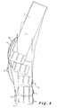
- Figure 4 is a schematic view illustrating the introduction of the supply container into the second element of the base unit according to the invention.
- Fig. 5 is a perspective view illustrating the particulate material dispensing device according to the invention, in its particular application as a freeze-dried beverage dispensing device.
- the first element 1 comprises a first base plate 2.
- the first element 1 further comprises a first rear wall 3 which extends substantially vertically.
- the first rear wall 3 comprises a first lower part 3a and a second upper part 3b, the first lower part at least is perpendicular to the first base plate 2.
- the first element 1 comprises a first and a second lateral wall 4 These side walls 4 are both substantially perpendicular to the first lower part 3a and to the first base plate 2.
- a first fastening means 5 is At the front of the first base plate 2 a first fastening means 5.
- the first base plate is positioned relatively horizontally so that a supply container 7 of particulate material can be placed thereon (see also Figures 4 and 5).
- the first base plate 2 actually serves as a support or support surface for the aforesaid container 7, possibly equipped with its base 6, which will also sometimes be called the cartridge 7 provided with its base 6.
- the first element 1 also comprises at least one first pivot means 14 which may be an orifice in which a protuberance will be housed or a protrusion intended to be housed in an orifice.
- the outer member comprises a pivot means which is a protuberance 14, this protuberance 14 is located on the inner upper part of each lateral face 4, but it could be envisaged that this protuberance 14 or possibly the orifice are located anywhere on the first element 1, or even on a single side wall 4.
- FIG. 2 an illustration of the second element 10 can be seen.
- This second element 10 is intended to be placed in the first element 1. It comprises at least a second base plate 11.
- the second base plate 11 is substantially horizontal. . It is intended to support the possible cartridge of particulate matter 7 provided with its base 6 and has a surface slightly greater than the surface of the base of the base 6.
- the second member 10 further comprises a second rear wall 12 which extends substantially vertically.
- the second wall 12 comprises a third lower portion 12a and a fourth portion 12b high.
- the third bottom portion 12a is at least substantially perpendicular to the second base plate 11.
- the second element 10 also comprises a third and a fourth lateral wall 13. These two lateral walls 13 are both substantially perpendicular to the third lower part 12a and to the second base plate 11.
- the second element comprises in the embodiment a pivot means 15 which is reciprocal to the first pivot means 14.
- the pivot means 15 in the preferred embodiment illustrated is an orifice 15 provided for receiving the protuberance 14.
- the pivot means 14 could be an orifice and that the pivot means 15 could be a protrusion, that these reciprocal pivot means can be located anywhere on the first element and on the second element and that they can be 1 or 2 in number.
- the second rear wall comprises, in this embodiment, two rows of openings 18 which each comprise orifices 19 which are provided to receive a shim and a guiding means 17.
- guide means 17 is advantageously a raised rail, but the skilled person will consider alternatives without any effort such as for example a pair of grooves, hollow grooves, rails in relief, a single groove or groove or any other means of analogous guidance.
- Figure 3 illustrates the base unit 21 according to the invention in the mounted state.
- the second element 10 is housed in the outer element 1.
- this embodiment is the embodiment in which the second upper part 3b and the fourth upper part 12b are curved parts which each have the same shape. one of the other similar curvatures to allow the second element 10 can be housed in the first element 1.
- the second element also comprises a front face 23 optionally equipped with a grooving.
- FIG 4 illustrates in profile the steps of introduction of the supply container 7 provided with its base 6 in the second element 10 of the base unit 21 according to the invention.
- the first element has been removed from the representation.
- the second rear wall 12 comprises guiding means 17.
- the base 6 of the cartridge 7 comprises at least two edges lateral flanges which each comprise flanges 16.
- flanges means for example lateral extensions which extend lower than the bottom of the base 6 and which define in this manner projections on either side of the bottom of the base 6.
- the flanges 16 are provided for sliding on either side of the raised rail 17 of the second rear wall 12.
- One variant would be to replace the flanges with grooves.
- the raised rail 17 would be replaced by raised grooves that would engage in the aforementioned grooves.
- the projections are longer and that they are designed to engage each in a rail located on the second rear wall of the second element.
- many engagement devices can be applied to replace the embossed rail 17 and the flanges 16, it is clear that all these engagement devices are included in the scope of the invention.
- the user has only to place the cartridge 7 provided with its base 6 near the top of the raised rail 17. It then adjusts the flanges 16 on either side of the rail. relief 17 in question and the cartridge 7 of particulate matter is guided downwards thanks to the particular shape of the rail 17 and the rear walls 3, 12; the gravity and the gesture of the user.
- the gesture of the latter is in fact a fluid gesture quite natural, just support the cartridge 7 and when descending lift it slightly vertical.
- Figure 5 illustrates the base unit 21 secured by attachment means to a lyophilized beverage dispensing device 20 in which the cartridge 7 or particulate material supply container 7 is placed.
- the left half of the first element 1 has been voluntarily removed in order to better illustrate the operation of the interior.
- the cartridge 7 rests on the second base plate 11.
- the base 6 of the cartridge 7 comprises an opening drawer 8.
- the opening drawer 8 can be in the open position or in the closed position. When the drawer is in the open position, it allows a release of a certain amount of particulate matter, this is the position shown in this figure.
- the drawer 8 is preferably composed of a four-sided frame (two lateral and two frontal), two of which (the two lateral faces) are arranged substantially parallel to the flanges 16 and set back with respect to the flanges 16.
- the particulate matter may be a freeze-dried tea coffee, soup or any other beverage that can be found in a lyophilized form to which water will still be added, but it may also be a soap powder, toothpaste, spices, sugar, flour or any other material in the form of a powder or granule which could find utility in such a dispenser.
- the drawer comprises a second fixing means 9 which is reciprocal to the first means 5.
- the drawer is secured to the first element in both the closed position and the open position.
- the aforementioned fastening means are chosen from fastening means consisting of at least one orifice 22 and at least one protrusion intended to be housed in the orifice 22 or at least one notch 9 and at least one protrusion 5 provided to be housed in the notch 9 or the two aforementioned couples of fixing means together. Inverses are also possible each time.
- the protuberance 5 When the protuberance 5 is housed in the notch of the front face of the drawer, it is fixed to the first element 1 of the base unit 21 according to the invention.
- this pressure In order for the container to deliver a quantity of particulate matter, it suffices to exert pressure on the end face 22, this pressure has the effect of causing the supply container / cartridge 7 to move backwards, the device is in the delivery position of product and a quantity of product falls for example into the container provided for this purpose.
- the pressure by the user causes the cartridge to rotate slightly by the presence of the pivot means 14 and 15, the bottom of the cartridge moves backwards, the front face of the slide being fixed, the device is in the product delivery position and a quantity of product falls for example into the container provided for this purpose.
- the first internal element does not have a front face, in the case the user exerts a direct pressure on the cartridge, and the effect obtained described just above is the same.
- the supply container is placed in the first element 1, in this case the cartridge rests directly on the first base plate 2.
- the user exercises a pressure directly on the cartridge, it moves backwards with a translational movement, as the front of the supply drawer is secured to the first element, the device is in the product delivery position and a quantity of product falls for example into the container provided for this purpose.
- the first base plate comprises grooves or grooves for guiding either the flanges of the base of the cartridge or directly the base of the cartridge, the presence of the flanges being preferred for reasons of reduced resistance of the cartridge. friction.
- the rows of openings 18 could also be located on the first rear wall 3. It would retain its role of limiting the angle of rotation, but its accessibility would be reduced.
- the wedge in question can be crescent moon, I, L or U or any other form at least one end can be easily inserted into one of the orifices 19.
- the second element 10 is housed in the first element 1, the cartridge 7 rests on the second base plate 11, but the pivot means 14, 15 are replaced by translation means.
- the first base plate 2 comprises grooves or grooves or a large groove for guiding the second base plate 11.
- the user wants to use the device according to the invention it exerts a pressure on a front wall of the second element or directly on the cartridge, if there is no front face on the second element.
- the front face of the drawer being fixed and integral with the external element, the pressure exerted by the user will result in a translation movement towards the rear of the second element containing the cartridge, the device is in the position of delivery of product and a quantity of product falls for example into the container provided for this purpose.
- the second upper portion 3b is an inclined portion of an angle of between 91 ° and 135 ° in a trigonometric marker.
- the first base plate 2 being positioned in said trigonometric marker with an angle substantially zero or equal to 180 °, ie substantially horizontal.
- the fourth high part 12b is then also inclined by one an angle substantially equal to the angle of inclination of the second top portion 3b. This inclination facilitates the insertion of the cartridge.
- a guiding means 17 which makes it possible to guide the flanges 16, if any, of the base 6 of the cartridge 7.
- This further facilitates the introduction of the cartridge 7 into the base unit 21 according to the invention.
- the user has only to place the cartridge 7 provided with its base 6 near the top of the raised rail 17. It then adjusts the flanges 16 on both sides of the raised rail 17 in question and the cartridge 7 of particulate material is guided downwards thanks to the particular shape of the rail 17 and the rear walls 3, 12; the gravity and the gesture of the user. It suffices to support the cartridge 7 and during its descent to raise slightly vertically at the location of the joint between the lower third portion 12a and the fourth top portion 12b.
- FIG. 1 it is possible to limit the translation of the cartridge 7 into the first element 1 by inserting a wedge into one of the orifices 19 of the rows of openings 18 provided on the base plate. 2 of the first element. This has the effect of limiting the possible distance of translation to the rear of the base 6 of the cartridge 7. Therefore, the relative opening between the cartridge 7 and the drawer 8 is also limited as the amount of particulate matter delivered.
- the first rear wall 3 could also have the guide rail 17 to facilitate the insertion of the cartridge 7.
Landscapes
- Engineering & Computer Science (AREA)
- Food Science & Technology (AREA)
- Apparatus For Making Beverages (AREA)
- Drying Of Solid Materials (AREA)
- Non-Alcoholic Beverages (AREA)
- Filling Or Emptying Of Bunkers, Hoppers, And Tanks (AREA)
- Coating Apparatus (AREA)
- Feeding, Discharge, Calcimining, Fusing, And Gas-Generation Devices (AREA)
- Nozzles (AREA)
Priority Applications (6)
| Application Number | Priority Date | Filing Date | Title |
|---|---|---|---|
| DK05103178T DK1714596T3 (da) | 2005-04-20 | 2005-04-20 | Indretning til fordeling af pulverformet materiale, navnlig frysetörrede drikke |
| EP05103178A EP1714596B1 (fr) | 2005-04-20 | 2005-04-20 | Dispositif de distribution d'une matière en poudre, en particulier de boissons liophilisées |
| DE602005002129T DE602005002129T2 (de) | 2005-04-20 | 2005-04-20 | Vorrichtung zur Ausgabe eines partikelförmigen Gutes |
| AT05103178T ATE370695T1 (de) | 2005-04-20 | 2005-04-20 | Vorrichtung zur ausgabe von pulverförmigem material |
| NO20061483A NO20061483L (no) | 2005-04-20 | 2006-03-31 | Anordning for a utlevere et materiale i pulverform |
| US11/406,287 US20060237482A1 (en) | 2005-04-20 | 2006-04-19 | Device for dispensing a material in powder form, in particular freeze-dried drinks |
Applications Claiming Priority (1)
| Application Number | Priority Date | Filing Date | Title |
|---|---|---|---|
| EP05103178A EP1714596B1 (fr) | 2005-04-20 | 2005-04-20 | Dispositif de distribution d'une matière en poudre, en particulier de boissons liophilisées |
Publications (2)
| Publication Number | Publication Date |
|---|---|
| EP1714596A1 EP1714596A1 (fr) | 2006-10-25 |
| EP1714596B1 true EP1714596B1 (fr) | 2007-08-22 |
Family
ID=34939407
Family Applications (1)
| Application Number | Title | Priority Date | Filing Date |
|---|---|---|---|
| EP05103178A Expired - Lifetime EP1714596B1 (fr) | 2005-04-20 | 2005-04-20 | Dispositif de distribution d'une matière en poudre, en particulier de boissons liophilisées |
Country Status (6)
| Country | Link |
|---|---|
| US (1) | US20060237482A1 (da) |
| EP (1) | EP1714596B1 (da) |
| AT (1) | ATE370695T1 (da) |
| DE (1) | DE602005002129T2 (da) |
| DK (1) | DK1714596T3 (da) |
| NO (1) | NO20061483L (da) |
Families Citing this family (2)
| Publication number | Priority date | Publication date | Assignee | Title |
|---|---|---|---|---|
| GB2451446A (en) * | 2007-07-30 | 2009-02-04 | Packaging Innovation Ltd | Hand held sprayer with dump valve |
| JP6818338B2 (ja) * | 2016-07-29 | 2021-01-20 | 江部松商事株式会社 | ソースディスペンサースタンド |
Family Cites Families (4)
| Publication number | Priority date | Publication date | Assignee | Title |
|---|---|---|---|---|
| US2237189A (en) * | 1938-05-06 | 1941-04-01 | Ralph D Mccormack | Ice dispenser |
| US3393838A (en) * | 1966-07-11 | 1968-07-23 | Fountain Industries | Storage container and dispenser |
| US3955718A (en) * | 1975-05-19 | 1976-05-11 | United Ventures, Inc. | Container vibrator mechanism for use in a vending machine |
| NL1019166C1 (nl) * | 2001-02-16 | 2002-08-19 | Peter B V | Inrichting voor het doseren van gesneden ui. |
-
2005
- 2005-04-20 DK DK05103178T patent/DK1714596T3/da active
- 2005-04-20 EP EP05103178A patent/EP1714596B1/fr not_active Expired - Lifetime
- 2005-04-20 AT AT05103178T patent/ATE370695T1/de not_active IP Right Cessation
- 2005-04-20 DE DE602005002129T patent/DE602005002129T2/de not_active Expired - Fee Related
-
2006
- 2006-03-31 NO NO20061483A patent/NO20061483L/no not_active Application Discontinuation
- 2006-04-19 US US11/406,287 patent/US20060237482A1/en not_active Abandoned
Also Published As
| Publication number | Publication date |
|---|---|
| DE602005002129T2 (de) | 2008-05-21 |
| DE602005002129D1 (de) | 2007-10-04 |
| ATE370695T1 (de) | 2007-09-15 |
| DK1714596T3 (da) | 2007-12-03 |
| EP1714596A1 (fr) | 2006-10-25 |
| US20060237482A1 (en) | 2006-10-26 |
| NO20061483L (no) | 2006-10-23 |
Similar Documents
| Publication | Publication Date | Title |
|---|---|---|
| EP1702658B1 (fr) | Dispositif de fixation a double commande | |
| FR2901116A1 (fr) | Distributeur de fluide | |
| FR2644412A1 (fr) | Systeme de table escamotable | |
| FR2602412A1 (fr) | Distributeur de liquide | |
| FR2725477A1 (fr) | Ensemble de pompe portative | |
| FR2889507A1 (fr) | Dispositif de distribution de touillettes | |
| FR2912617A1 (fr) | Boitier pour produit cosmetique ou d'hygiene du corps a couvercle escamotable | |
| FR2929819A1 (fr) | Dispositif de distribution et de dosage alimentaire pulverulent. | |
| WO2011069956A1 (fr) | Table à rallonge | |
| FR2948549A1 (fr) | Cuillere doseuse | |
| EP1714596B1 (fr) | Dispositif de distribution d'une matière en poudre, en particulier de boissons liophilisées | |
| FR2475871A3 (fr) | Bras support pour siege ou fauteuil comportant un accoudoir relevable | |
| EP2732745B1 (fr) | Dispositif de toilette sèche | |
| FR2969130A1 (fr) | Dispositif de distribution de liquide. | |
| FR2745192A1 (fr) | Dispositif de retenue d'une chaussure sur une planche de glisse. | |
| FR2976791A1 (fr) | Barriere de lit escamotable | |
| FR2755431A1 (fr) | Distributeur-doseur de produit granulaire ou pulverulent | |
| FR2772583A1 (fr) | Distributeur de produit de nettoyage, de type savon liquide ou semi-liquide | |
| FR3036121A1 (fr) | Appareil electromenager de repassage comportant un fer a repasser et une base comprenant un emplacement pour poser le fer a repasser | |
| WO2015185838A1 (fr) | Appareil d'entraînement physique aquatique immerge dans un bac pivotant | |
| EP3912536A1 (fr) | Machine de preparation de boissons equipee d'une tete de distribution de fluide mobile en translation | |
| EP1545720A1 (fr) | Distributeur de balles de golf | |
| FR3073377A1 (fr) | Dispositif pour la fixation amovible d'une etagere | |
| EP2379183A1 (fr) | Raquette a neige a cale de montee | |
| EP1025882A1 (fr) | Ensemble chaussure-fixation de ski de sécurité |
Legal Events
| Date | Code | Title | Description |
|---|---|---|---|
| PUAI | Public reference made under article 153(3) epc to a published international application that has entered the european phase |
Free format text: ORIGINAL CODE: 0009012 |
|
| 17P | Request for examination filed |
Effective date: 20050815 |
|
| AK | Designated contracting states |
Kind code of ref document: A1 Designated state(s): AT BE BG CH CY CZ DE DK EE ES FI FR GB GR HU IE IS IT LI LT LU MC NL PL PT RO SE SI SK TR |
|
| AX | Request for extension of the european patent |
Extension state: AL BA HR LV MK YU |
|
| GRAP | Despatch of communication of intention to grant a patent |
Free format text: ORIGINAL CODE: EPIDOSNIGR1 |
|
| GRAS | Grant fee paid |
Free format text: ORIGINAL CODE: EPIDOSNIGR3 |
|
| AKX | Designation fees paid |
Designated state(s): AT BE BG CH CY CZ DE DK EE ES FI FR GB GR HU IE IS IT LI LT LU MC NL PL PT RO SE SI SK TR |
|
| GRAA | (expected) grant |
Free format text: ORIGINAL CODE: 0009210 |
|
| AK | Designated contracting states |
Kind code of ref document: B1 Designated state(s): AT BE BG CH CY CZ DE DK EE ES FI FR GB GR HU IE IS IT LI LT LU MC NL PL PT RO SE SI SK TR |
|
| REG | Reference to a national code |
Ref country code: GB Ref legal event code: FG4D Free format text: NOT ENGLISH |
|
| REG | Reference to a national code |
Ref country code: CH Ref legal event code: EP |
|
| REG | Reference to a national code |
Ref country code: IE Ref legal event code: FG4D Free format text: LANGUAGE OF EP DOCUMENT: FRENCH |
|
| REF | Corresponds to: |
Ref document number: 602005002129 Country of ref document: DE Date of ref document: 20071004 Kind code of ref document: P |
|
| GBT | Gb: translation of ep patent filed (gb section 77(6)(a)/1977) |
Effective date: 20071002 |
|
| REG | Reference to a national code |
Ref country code: CH Ref legal event code: NV Representative=s name: DR. LUSUARDI AG |
|
| REG | Reference to a national code |
Ref country code: DK Ref legal event code: T3 |
|
| REG | Reference to a national code |
Ref country code: SE Ref legal event code: TRGR |
|
| PG25 | Lapsed in a contracting state [announced via postgrant information from national office to epo] |
Ref country code: LT Free format text: LAPSE BECAUSE OF FAILURE TO SUBMIT A TRANSLATION OF THE DESCRIPTION OR TO PAY THE FEE WITHIN THE PRESCRIBED TIME-LIMIT Effective date: 20070822 Ref country code: ES Free format text: LAPSE BECAUSE OF FAILURE TO SUBMIT A TRANSLATION OF THE DESCRIPTION OR TO PAY THE FEE WITHIN THE PRESCRIBED TIME-LIMIT Effective date: 20071203 Ref country code: BG Free format text: LAPSE BECAUSE OF FAILURE TO SUBMIT A TRANSLATION OF THE DESCRIPTION OR TO PAY THE FEE WITHIN THE PRESCRIBED TIME-LIMIT Effective date: 20071122 Ref country code: IS Free format text: LAPSE BECAUSE OF FAILURE TO SUBMIT A TRANSLATION OF THE DESCRIPTION OR TO PAY THE FEE WITHIN THE PRESCRIBED TIME-LIMIT Effective date: 20071222 |
|
| PG25 | Lapsed in a contracting state [announced via postgrant information from national office to epo] |
Ref country code: PL Free format text: LAPSE BECAUSE OF FAILURE TO SUBMIT A TRANSLATION OF THE DESCRIPTION OR TO PAY THE FEE WITHIN THE PRESCRIBED TIME-LIMIT Effective date: 20070822 Ref country code: AT Free format text: LAPSE BECAUSE OF FAILURE TO SUBMIT A TRANSLATION OF THE DESCRIPTION OR TO PAY THE FEE WITHIN THE PRESCRIBED TIME-LIMIT Effective date: 20070822 |
|
| REG | Reference to a national code |
Ref country code: IE Ref legal event code: FD4D |
|
| PG25 | Lapsed in a contracting state [announced via postgrant information from national office to epo] |
Ref country code: GR Free format text: LAPSE BECAUSE OF FAILURE TO SUBMIT A TRANSLATION OF THE DESCRIPTION OR TO PAY THE FEE WITHIN THE PRESCRIBED TIME-LIMIT Effective date: 20071123 |
|
| PG25 | Lapsed in a contracting state [announced via postgrant information from national office to epo] |
Ref country code: IE Free format text: LAPSE BECAUSE OF FAILURE TO SUBMIT A TRANSLATION OF THE DESCRIPTION OR TO PAY THE FEE WITHIN THE PRESCRIBED TIME-LIMIT Effective date: 20070822 Ref country code: PT Free format text: LAPSE BECAUSE OF FAILURE TO SUBMIT A TRANSLATION OF THE DESCRIPTION OR TO PAY THE FEE WITHIN THE PRESCRIBED TIME-LIMIT Effective date: 20080122 Ref country code: SK Free format text: LAPSE BECAUSE OF FAILURE TO SUBMIT A TRANSLATION OF THE DESCRIPTION OR TO PAY THE FEE WITHIN THE PRESCRIBED TIME-LIMIT Effective date: 20070822 |
|
| PLBE | No opposition filed within time limit |
Free format text: ORIGINAL CODE: 0009261 |
|
| STAA | Information on the status of an ep patent application or granted ep patent |
Free format text: STATUS: NO OPPOSITION FILED WITHIN TIME LIMIT |
|
| PG25 | Lapsed in a contracting state [announced via postgrant information from national office to epo] |
Ref country code: RO Free format text: LAPSE BECAUSE OF FAILURE TO SUBMIT A TRANSLATION OF THE DESCRIPTION OR TO PAY THE FEE WITHIN THE PRESCRIBED TIME-LIMIT Effective date: 20070822 |
|
| REG | Reference to a national code |
Ref country code: HU Ref legal event code: AG4A Ref document number: E002958 Country of ref document: HU |
|
| 26N | No opposition filed |
Effective date: 20080526 |
|
| PGFP | Annual fee paid to national office [announced via postgrant information from national office to epo] |
Ref country code: HU Payment date: 20080417 Year of fee payment: 4 |
|
| PG25 | Lapsed in a contracting state [announced via postgrant information from national office to epo] |
Ref country code: MC Free format text: LAPSE BECAUSE OF NON-PAYMENT OF DUE FEES Effective date: 20080430 |
|
| PG25 | Lapsed in a contracting state [announced via postgrant information from national office to epo] |
Ref country code: EE Free format text: LAPSE BECAUSE OF FAILURE TO SUBMIT A TRANSLATION OF THE DESCRIPTION OR TO PAY THE FEE WITHIN THE PRESCRIBED TIME-LIMIT Effective date: 20070822 |
|
| PG25 | Lapsed in a contracting state [announced via postgrant information from national office to epo] |
Ref country code: SI Free format text: LAPSE BECAUSE OF FAILURE TO SUBMIT A TRANSLATION OF THE DESCRIPTION OR TO PAY THE FEE WITHIN THE PRESCRIBED TIME-LIMIT Effective date: 20070822 |
|
| PG25 | Lapsed in a contracting state [announced via postgrant information from national office to epo] |
Ref country code: CY Free format text: LAPSE BECAUSE OF FAILURE TO SUBMIT A TRANSLATION OF THE DESCRIPTION OR TO PAY THE FEE WITHIN THE PRESCRIBED TIME-LIMIT Effective date: 20070822 |
|
| PGFP | Annual fee paid to national office [announced via postgrant information from national office to epo] |
Ref country code: DK Payment date: 20090415 Year of fee payment: 5 |
|
| PGFP | Annual fee paid to national office [announced via postgrant information from national office to epo] |
Ref country code: DE Payment date: 20090422 Year of fee payment: 5 Ref country code: FI Payment date: 20090417 Year of fee payment: 5 Ref country code: LU Payment date: 20090414 Year of fee payment: 5 Ref country code: NL Payment date: 20090331 Year of fee payment: 5 Ref country code: SE Payment date: 20090416 Year of fee payment: 5 |
|
| PGFP | Annual fee paid to national office [announced via postgrant information from national office to epo] |
Ref country code: BE Payment date: 20090427 Year of fee payment: 5 |
|
| PGFP | Annual fee paid to national office [announced via postgrant information from national office to epo] |
Ref country code: CH Payment date: 20090417 Year of fee payment: 5 Ref country code: FR Payment date: 20090324 Year of fee payment: 5 |
|
| PGFP | Annual fee paid to national office [announced via postgrant information from national office to epo] |
Ref country code: CZ Payment date: 20090914 Year of fee payment: 5 Ref country code: GB Payment date: 20090421 Year of fee payment: 5 |
|
| PG25 | Lapsed in a contracting state [announced via postgrant information from national office to epo] |
Ref country code: HU Free format text: LAPSE BECAUSE OF NON-PAYMENT OF DUE FEES Effective date: 20090421 |
|
| PG25 | Lapsed in a contracting state [announced via postgrant information from national office to epo] |
Ref country code: TR Free format text: LAPSE BECAUSE OF FAILURE TO SUBMIT A TRANSLATION OF THE DESCRIPTION OR TO PAY THE FEE WITHIN THE PRESCRIBED TIME-LIMIT Effective date: 20070822 |
|
| BERE | Be: lapsed |
Owner name: FOUNTAIN SA Effective date: 20100430 |
|
| REG | Reference to a national code |
Ref country code: NL Ref legal event code: V1 Effective date: 20101101 |
|
| EUG | Se: european patent has lapsed | ||
| REG | Reference to a national code |
Ref country code: CH Ref legal event code: PL |
|
| REG | Reference to a national code |
Ref country code: DK Ref legal event code: EBP |
|
| GBPC | Gb: european patent ceased through non-payment of renewal fee |
Effective date: 20100420 |
|
| REG | Reference to a national code |
Ref country code: FR Ref legal event code: ST Effective date: 20101230 |
|
| PG25 | Lapsed in a contracting state [announced via postgrant information from national office to epo] |
Ref country code: NL Free format text: LAPSE BECAUSE OF NON-PAYMENT OF DUE FEES Effective date: 20101101 Ref country code: FI Free format text: LAPSE BECAUSE OF NON-PAYMENT OF DUE FEES Effective date: 20100420 |
|
| PG25 | Lapsed in a contracting state [announced via postgrant information from national office to epo] |
Ref country code: CZ Free format text: LAPSE BECAUSE OF NON-PAYMENT OF DUE FEES Effective date: 20100420 Ref country code: LI Free format text: LAPSE BECAUSE OF NON-PAYMENT OF DUE FEES Effective date: 20100430 Ref country code: IT Free format text: LAPSE BECAUSE OF NON-PAYMENT OF DUE FEES Effective date: 20080430 Ref country code: DE Free format text: LAPSE BECAUSE OF NON-PAYMENT OF DUE FEES Effective date: 20101103 Ref country code: CH Free format text: LAPSE BECAUSE OF NON-PAYMENT OF DUE FEES Effective date: 20100430 |
|
| PG25 | Lapsed in a contracting state [announced via postgrant information from national office to epo] |
Ref country code: GB Free format text: LAPSE BECAUSE OF NON-PAYMENT OF DUE FEES Effective date: 20100420 Ref country code: BE Free format text: LAPSE BECAUSE OF NON-PAYMENT OF DUE FEES Effective date: 20100430 |
|
| PG25 | Lapsed in a contracting state [announced via postgrant information from national office to epo] |
Ref country code: DK Free format text: LAPSE BECAUSE OF NON-PAYMENT OF DUE FEES Effective date: 20100503 |
|
| PG25 | Lapsed in a contracting state [announced via postgrant information from national office to epo] |
Ref country code: FR Free format text: LAPSE BECAUSE OF NON-PAYMENT OF DUE FEES Effective date: 20100430 |
|
| PG25 | Lapsed in a contracting state [announced via postgrant information from national office to epo] |
Ref country code: LU Free format text: LAPSE BECAUSE OF NON-PAYMENT OF DUE FEES Effective date: 20100420 Ref country code: SE Free format text: LAPSE BECAUSE OF NON-PAYMENT OF DUE FEES Effective date: 20100421 |