EP1714239B1 - Device and method for encapsulation and mounting of rfid devices - Google Patents
Device and method for encapsulation and mounting of rfid devices Download PDFInfo
- Publication number
- EP1714239B1 EP1714239B1 EP04815909.9A EP04815909A EP1714239B1 EP 1714239 B1 EP1714239 B1 EP 1714239B1 EP 04815909 A EP04815909 A EP 04815909A EP 1714239 B1 EP1714239 B1 EP 1714239B1
- Authority
- EP
- European Patent Office
- Prior art keywords
- layer
- rfid device
- rfid
- art image
- tag
- Prior art date
- Legal status (The legal status is an assumption and is not a legal conclusion. Google has not performed a legal analysis and makes no representation as to the accuracy of the status listed.)
- Active
Links
- 238000000034 method Methods 0.000 title claims description 41
- 238000005538 encapsulation Methods 0.000 title description 10
- 239000010410 layer Substances 0.000 claims description 91
- 239000000463 material Substances 0.000 claims description 57
- 239000000758 substrate Substances 0.000 claims description 29
- 239000012790 adhesive layer Substances 0.000 claims description 23
- -1 polyethylene Polymers 0.000 claims description 10
- 229920000728 polyester Polymers 0.000 claims description 9
- 229920002635 polyurethane Polymers 0.000 claims description 7
- 239000004814 polyurethane Substances 0.000 claims description 7
- 239000004593 Epoxy Substances 0.000 claims description 5
- 239000004698 Polyethylene Substances 0.000 claims description 3
- 239000004743 Polypropylene Substances 0.000 claims description 3
- 239000004793 Polystyrene Substances 0.000 claims description 3
- 229920000573 polyethylene Polymers 0.000 claims description 3
- 229920001155 polypropylene Polymers 0.000 claims description 3
- 229920002223 polystyrene Polymers 0.000 claims description 3
- 239000003522 acrylic cement Substances 0.000 claims description 2
- 238000005034 decoration Methods 0.000 claims description 2
- 230000008569 process Effects 0.000 description 27
- 230000005540 biological transmission Effects 0.000 description 11
- 239000000853 adhesive Substances 0.000 description 6
- 230000001070 adhesive effect Effects 0.000 description 6
- 238000004519 manufacturing process Methods 0.000 description 6
- 101100406385 Caenorhabditis elegans ola-1 gene Proteins 0.000 description 3
- 238000005516 engineering process Methods 0.000 description 3
- 238000002372 labelling Methods 0.000 description 3
- 239000004033 plastic Substances 0.000 description 3
- 229920003023 plastic Polymers 0.000 description 3
- 238000000926 separation method Methods 0.000 description 3
- CWYNVVGOOAEACU-UHFFFAOYSA-N Fe2+ Chemical compound [Fe+2] CWYNVVGOOAEACU-UHFFFAOYSA-N 0.000 description 2
- 230000008901 benefit Effects 0.000 description 2
- 239000007788 liquid Substances 0.000 description 2
- 239000000696 magnetic material Substances 0.000 description 2
- 239000002184 metal Substances 0.000 description 2
- 229910052751 metal Inorganic materials 0.000 description 2
- 230000004048 modification Effects 0.000 description 2
- 238000012986 modification Methods 0.000 description 2
- 239000011347 resin Substances 0.000 description 2
- 229920005989 resin Polymers 0.000 description 2
- 230000004044 response Effects 0.000 description 2
- 239000003566 sealing material Substances 0.000 description 2
- 239000000126 substance Substances 0.000 description 2
- 229920000114 Corrugated plastic Polymers 0.000 description 1
- 239000003082 abrasive agent Substances 0.000 description 1
- 238000010521 absorption reaction Methods 0.000 description 1
- 229920006397 acrylic thermoplastic Polymers 0.000 description 1
- 230000002411 adverse Effects 0.000 description 1
- 239000000956 alloy Substances 0.000 description 1
- 229910045601 alloy Inorganic materials 0.000 description 1
- 230000015572 biosynthetic process Effects 0.000 description 1
- 230000015556 catabolic process Effects 0.000 description 1
- 239000000919 ceramic Substances 0.000 description 1
- 239000002131 composite material Substances 0.000 description 1
- 238000006731 degradation reaction Methods 0.000 description 1
- 230000000694 effects Effects 0.000 description 1
- 229920001971 elastomer Polymers 0.000 description 1
- 230000007613 environmental effect Effects 0.000 description 1
- 239000012530 fluid Substances 0.000 description 1
- 239000011521 glass Substances 0.000 description 1
- 230000005484 gravity Effects 0.000 description 1
- 238000011065 in-situ storage Methods 0.000 description 1
- 238000002347 injection Methods 0.000 description 1
- 239000007924 injection Substances 0.000 description 1
- 150000002739 metals Chemical class 0.000 description 1
- 239000002991 molded plastic Substances 0.000 description 1
- 230000008520 organization Effects 0.000 description 1
- 239000005022 packaging material Substances 0.000 description 1
- 238000004806 packaging method and process Methods 0.000 description 1
- 239000000123 paper Substances 0.000 description 1
- 229920001084 poly(chloroprene) Polymers 0.000 description 1
- 229920003229 poly(methyl methacrylate) Polymers 0.000 description 1
- ISXSCDLOGDJUNJ-UHFFFAOYSA-N tert-butyl prop-2-enoate Chemical compound CC(C)(C)OC(=O)C=C ISXSCDLOGDJUNJ-UHFFFAOYSA-N 0.000 description 1
Images


Classifications
-
- G—PHYSICS
- G06—COMPUTING; CALCULATING OR COUNTING
- G06K—GRAPHICAL DATA READING; PRESENTATION OF DATA; RECORD CARRIERS; HANDLING RECORD CARRIERS
- G06K19/00—Record carriers for use with machines and with at least a part designed to carry digital markings
- G06K19/06—Record carriers for use with machines and with at least a part designed to carry digital markings characterised by the kind of the digital marking, e.g. shape, nature, code
- G06K19/067—Record carriers with conductive marks, printed circuits or semiconductor circuit elements, e.g. credit or identity cards also with resonating or responding marks without active components
- G06K19/07—Record carriers with conductive marks, printed circuits or semiconductor circuit elements, e.g. credit or identity cards also with resonating or responding marks without active components with integrated circuit chips
- G06K19/077—Constructional details, e.g. mounting of circuits in the carrier
- G06K19/07749—Constructional details, e.g. mounting of circuits in the carrier the record carrier being capable of non-contact communication, e.g. constructional details of the antenna of a non-contact smart card
- G06K19/07758—Constructional details, e.g. mounting of circuits in the carrier the record carrier being capable of non-contact communication, e.g. constructional details of the antenna of a non-contact smart card arrangements for adhering the record carrier to further objects or living beings, functioning as an identification tag
- G06K19/0776—Constructional details, e.g. mounting of circuits in the carrier the record carrier being capable of non-contact communication, e.g. constructional details of the antenna of a non-contact smart card arrangements for adhering the record carrier to further objects or living beings, functioning as an identification tag the adhering arrangement being a layer of adhesive, so that the record carrier can function as a sticker
-
- G—PHYSICS
- G08—SIGNALLING
- G08B—SIGNALLING OR CALLING SYSTEMS; ORDER TELEGRAPHS; ALARM SYSTEMS
- G08B13/00—Burglar, theft or intruder alarms
- G08B13/22—Electrical actuation
- G08B13/24—Electrical actuation by interference with electromagnetic field distribution
- G08B13/2402—Electronic Article Surveillance [EAS], i.e. systems using tags for detecting removal of a tagged item from a secure area, e.g. tags for detecting shoplifting
- G08B13/2405—Electronic Article Surveillance [EAS], i.e. systems using tags for detecting removal of a tagged item from a secure area, e.g. tags for detecting shoplifting characterised by the tag technology used
- G08B13/2414—Electronic Article Surveillance [EAS], i.e. systems using tags for detecting removal of a tagged item from a secure area, e.g. tags for detecting shoplifting characterised by the tag technology used using inductive tags
- G08B13/2417—Electronic Article Surveillance [EAS], i.e. systems using tags for detecting removal of a tagged item from a secure area, e.g. tags for detecting shoplifting characterised by the tag technology used using inductive tags having a radio frequency identification chip
-
- G—PHYSICS
- G08—SIGNALLING
- G08B—SIGNALLING OR CALLING SYSTEMS; ORDER TELEGRAPHS; ALARM SYSTEMS
- G08B13/00—Burglar, theft or intruder alarms
- G08B13/22—Electrical actuation
- G08B13/24—Electrical actuation by interference with electromagnetic field distribution
- G08B13/2402—Electronic Article Surveillance [EAS], i.e. systems using tags for detecting removal of a tagged item from a secure area, e.g. tags for detecting shoplifting
- G08B13/2428—Tag details
- G08B13/2434—Tag housing and attachment details
-
- G—PHYSICS
- G08—SIGNALLING
- G08B—SIGNALLING OR CALLING SYSTEMS; ORDER TELEGRAPHS; ALARM SYSTEMS
- G08B13/00—Burglar, theft or intruder alarms
- G08B13/22—Electrical actuation
- G08B13/24—Electrical actuation by interference with electromagnetic field distribution
- G08B13/2402—Electronic Article Surveillance [EAS], i.e. systems using tags for detecting removal of a tagged item from a secure area, e.g. tags for detecting shoplifting
- G08B13/2428—Tag details
- G08B13/2437—Tag layered structure, processes for making layered tags
-
- Y—GENERAL TAGGING OF NEW TECHNOLOGICAL DEVELOPMENTS; GENERAL TAGGING OF CROSS-SECTIONAL TECHNOLOGIES SPANNING OVER SEVERAL SECTIONS OF THE IPC; TECHNICAL SUBJECTS COVERED BY FORMER USPC CROSS-REFERENCE ART COLLECTIONS [XRACs] AND DIGESTS
- Y10—TECHNICAL SUBJECTS COVERED BY FORMER USPC
- Y10T—TECHNICAL SUBJECTS COVERED BY FORMER US CLASSIFICATION
- Y10T156/00—Adhesive bonding and miscellaneous chemical manufacture
- Y10T156/10—Methods of surface bonding and/or assembly therefor
-
- Y—GENERAL TAGGING OF NEW TECHNOLOGICAL DEVELOPMENTS; GENERAL TAGGING OF CROSS-SECTIONAL TECHNOLOGIES SPANNING OVER SEVERAL SECTIONS OF THE IPC; TECHNICAL SUBJECTS COVERED BY FORMER USPC CROSS-REFERENCE ART COLLECTIONS [XRACs] AND DIGESTS
- Y10—TECHNICAL SUBJECTS COVERED BY FORMER USPC
- Y10T—TECHNICAL SUBJECTS COVERED BY FORMER US CLASSIFICATION
- Y10T29/00—Metal working
- Y10T29/49—Method of mechanical manufacture
- Y10T29/49002—Electrical device making
- Y10T29/49016—Antenna or wave energy "plumbing" making
-
- Y—GENERAL TAGGING OF NEW TECHNOLOGICAL DEVELOPMENTS; GENERAL TAGGING OF CROSS-SECTIONAL TECHNOLOGIES SPANNING OVER SEVERAL SECTIONS OF THE IPC; TECHNICAL SUBJECTS COVERED BY FORMER USPC CROSS-REFERENCE ART COLLECTIONS [XRACs] AND DIGESTS
- Y10—TECHNICAL SUBJECTS COVERED BY FORMER USPC
- Y10T—TECHNICAL SUBJECTS COVERED BY FORMER US CLASSIFICATION
- Y10T29/00—Metal working
- Y10T29/49—Method of mechanical manufacture
- Y10T29/49002—Electrical device making
- Y10T29/49117—Conductor or circuit manufacturing
Definitions
- the present invention relates generally to radio frequency identification (RFID) devices and, more particularly, to the encapsulation and mounting of RFID devices. Specifically, the present invention relates to the domed encapsulation of RFID transponders and their mounting on surfaces that impede radio frequency (RF) transmissions.
- RFID radio frequency identification
- RF radio frequency
- Radio frequency identification is an information acquisition technology.
- RFID systems are generally designed to manage assets of many types.
- RFID systems are generally comprised of transponders (a/k/a "tags"), a transmitter to provide energy to the tags, a receiver to receive transmissions from the transponders, and a computer system to process the received information.
- the transmitter and receiver may be combined into a single device often referred to as an interrogator or reader.
- an interrogator or reader typically a small RFID tag is attached to the asset so that either the asset's presence at a certain location can be detected or the asset can be identified by the response of the tag to the interrogation either by hand-held interrogators or fixed-site interrogators that are encountered in the course of asset movement.
- the failure to detect an expected RFID signal may also be used as an indicator.
- RFID transponders may be exposed to a variety of harsh environments during the course of their use. For this reason, tags must be tolerant of many hostile chemicals, abrasives, weather conditions and mechanical stresses. Although RFID devices generally are packaged in a plastic housing, these housings may lack sufficient properties to withstand harsh environments for prolonged periods.
- Encapsulation of art images and advertising materials is a well-known process in the formation of domed labels.
- a process known as "domed encapsulation" provides an encapsulating material over a substrate on which artwork or advertising is placed.
- the encapsulating material is translucent, though in some instances it may be colored, tinted, or otherwise opaque.
- the encapsulating material makes the underlying art or advertisement stand out with a three-dimensional "wet" look and protects the artwork.
- the encapsulating material is comprised of an epoxy for an application where flexibility is not a requirement, or polyurethane where more flexibility is needed.
- the doming process depends on surface tension to form a bubble of the encapsulating material on an item being decorated without going off the edge of the item.
- the encapsulating material is applied to the substrate and, if required, then exposed to a hardening or curing process, such as exposure to ultra-violet light or heat.
- a hardening or curing process such as exposure to ultra-violet light or heat.
- Known uses of the encapsulating process are the creation of identification, advertising and artwork used on automobiles, computers and computer cases, name badges and lapel pins.
- RFID devices are commonly used on or near a number of surface materials.
- RF radio frequency
- materials proximate to the surface on which the RFID device is mounted may impede the transmission and reception of RF signals by the RFID device.
- An example would be a glass or plastic container holding a fluid that interferes with the transmission and reception of RF signals by an RFID device mounted on or within the container.
- a method and apparatus are needed to overcome challenges associated with the use of RFID devices, some of which are given above, including protecting RFID devices through encapsulation, overlaying the devices with images, and mounting the devices so that their reception and transmission of RF signals is not impeded.
- WO 96/08596 discloses a labelling device for laundry items, the labelling device comprising transponder means completely encapsulated within a resin system which has been solidified in situ around the transponder means, and a thermoadhesive layer for use in bonding the device to a laundry item to be labelled.
- EP0772152 discloses a chip carrier with a cover which can be permanently clipped to the carrier.
- the cover and the chip carrier enclose the chip.
- a fastener is formed on the chip carrier to non-releasably fasten the chip carrier to containers of different geometric dimensions.
- the invention provides a RFID tag according to claim 1 and a method of encapsulation according to claim 9.
- an RFID device such as, for example, an RFID transponder
- an RFID device is encapsulated by known domed encapsulation techniques to conceal the RFID device and form a protected RFID device for use in harsh environments.
- the embodiments of this invention provide a domed encapsulated RFID apparatus and method of forming the same, such that interference, attenuation and absorption ,of the radio frequency (RF) signal by the encapsulating material and by any surface on which the encapsulated RFID device is placed is minimized.
- RF radio frequency
- the packaging of RFID devices performs several functions, including environmental protection and concealment.
- the packaging material should be compatible with the RF performance of the tag to avoid degradation of the performance of the RFID system.
- the present invention involves encapsulating a standard RFID tag in a manner that will protect or conceal the RFID tag. Because of its use in artwork and labeling, domed encapsulation is relatively inexpensive. An economical way to encapsulate an RFID device is by using a domed polyester or polyurethane process.
- a spacing device holds an RFID device a distance away from a mounting surface so that RF interference caused by the mounting surface or nearby materials is lessened.
- an art image such as a logo, trademark slogan, etc. is encapsulated with the RFID tag.
- one or more surfaces of the encapsulated RFID tag may comprise an adhesive material to facilitate mounting of the encapsulated RFID tag on a body.
- a particular use of the invention is to track shipments, for example by being attached to a tractor or a trailer.
- An advantage of the invention is that the RFID device is concealed.
- the encapsulated RFID device of the invention may be used for one or more of a label, nametag, luggage tag, advertisement, key fob, emblem, automobile emblem, or decoration.
- the encapsulated RFID device may be comprised of one or more materials having certain thicknesses such that interference with RF signals is minimized.
- the invention may be used with a stand-off bracket configured to maintain an RFID device in the 860-928 MHz range a distance from a supporting surface.
- the bracket is useful on a surface or near a material that impedes or blocks RF transmission.
- the encapsulated RFID device may be mounted in the mirror assembly of a vehicle, or on a stand-off bracket within a mirror assembly of a vehicle.
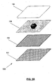
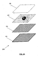
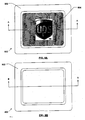
- FIG. 1A is an exploded view of the components that comprise an exemplary domed encapsulated RFID tag 100 in an embodiment of the invention.
- an adhesive layer 102 comprised of an approximately 2 millimeter (mil) thick acrylic adhesive liner is substantially attached to and underlies an RFID device 104, though other thicknesses and types of adhesive may be used.
- this adhesive layer 102 has an adhesive on its exposed surface such that it can be adhesively mounted to another surface and an adhesive on the surface that is substantially in contact with the RFID device 104 such that the adhesive layer 102 is adhered to the RFID device 104.
- the adhesive layer 102 may be dimensioned such that it extends beyond each edge of the RFID device 104 when the adhesive layer is substantially adhered to the RFID device 104, the adhesive layer 102 may be of the same dimensions as the RFID device 104 to which it is substantially adhered, or the adhesive layer 102 may be of smaller dimensions than the RFID device 104 to which it is substantially adhered.
- an image layer 106 comprised of an approximately 2.4-mil thick polyester image layer substantially lies over the RFID device 104, although in other embodiments the image layer 106 may lie substantially underneath the RFID device 104, or be composed of different materials and/or thicknesses. At least one surface of the image layer 106 is substantially adhered to the RFID device 104. If the image layer 106 substantially lies underneath the RFID device 104, one surface of the image layer 106 is adhered to the RFID device 104 and a second surface of the image layer 106 is substantially adhered to the adhesive layer 102.
- the image layer substantially lies over the RFID device 104, one surface of the image layer is adhered to the RFID device 104 and a second surface of the image layer 106 is substantially adhered to a dome layer 108.
- the dome layer 108 such as, for example, a clear, flexible, polyurethane dome, is placed over the image layer 106 or, if the image layer 106 is omitted or lies substantially underneath the RFID device 104, the dome layer 108 is placed over the RFID device 104.
- the adhesive layer 102 is dimensioned such that it extends beyond any dimension of the RFID device 104, then the dome layer 108 may be in contact with the adhesive layer 102, thereby encapsulating the RFID device 104.
- the dome layer 108 may be of the same dimensions as the underlying RFID device 104, or the dome layer may have smaller dimensions than the RFID device.
- the RFID device 104 is substantially sealed from atmospheric exposure, protected, or concealed by the encapsulation.
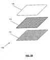
- FIG. 1B is another embodiment of the encapsulated RFID device shown in FIG. 1A .
- the encapsulated RFID device 110 is comprised of an adhesive layer 112 , an RFID device 114 , and a dome layer 116.
- the image layer is omitted from this embodiment, as compared to the embodiment of FIG. 1A .
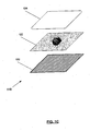
- FIG. 1C is yet another embodiment of the encapsulated RFID device shown in FIG. 1A .
- the encapsulated RFID device 118 is comprised of an RFID device 120 , an image layer 122 , and a dome layer 124.
- the adhesive layer is omitted from this embodiment, as compared to the embodiment of FIG. 1A .
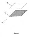
- FIG. 1D is another embodiment of the encapsulated RFID device shown in FIG. 1A .
- the encapsulated RFID device 126 is comprised of an RFID device 128 and a dome layer 130.
- the adhesive layer and the image layer are each omitted from this embodiment, as compared to the embodiment of FIG. 1A .
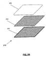
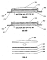
- an exemplary domed, encapsulated RFID tag 200 is comprised of a substrate layer 202 , an RFID device 204 , an art image 206 , and a dome layer 208.
- the substrate layer 202 may be comprised of a flexible, rigid, or semi-rigid material such as, for example, plastics, ferrous or non-ferrous metals, ceramics, composites, alloys, etc.
- the substrate layer 202 may have an adhesive on its exposed surface to attach the encapsulated RFID tag 200 to another surface.
- the substrate layer 202 may have attached or embedded magnets to affix the encapsulated RFID tag 200 to a surface containing magnetic material.
- the substrate layer 202 itself may be magnetized, thus making it capable of being affixed to a surface containing magnetic material.
- the substrate layer 202 may have other means of attachment to another surface such as a pin or clasp for attaching to an article of apparel, a split ring, lanyard, snap, buckle, screw, clamp, etc.
- An RFID device 204 is substantially affixed to the substrate layer 202.
- the RFID device 204 is substantially adhered to the substrate layer 202 ; however, in other embodiments the RFID device 204 may be clamped, screwed, welded, nailed, stapled, sewn, magnetically-held, or otherwise affixed to the substrate layer 202.
- the RFID device 204 is substantially encapsulated in an encapsulating material 208, thereby providing protection to the RFID device 204 and, in some instances, concealing the RFID device 204.
- an art image 206 such as, for example, a corporation or other form of entity's logo or trademark, overlays the RFID device 204 and is substantially encapsulated in the encapsulating material 208 along with the RFID device 204.
- FIG. 2B is an exploded view of the components that comprise an exemplary domed encapsulated RFID tag 210 in another embodiment of the invention having a base substrate 212.
- the encapsulated RFID tag 210 is comprised of a base substrate 212, an RFID device 214, and an encapsulating material 216.
- FIG. 2B illustrates an embodiment of an encapsulated RFID tag 210 wherein the art image layer is omitted.
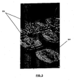
- FIG. 3 is an image of a manufacturing process for an exemplary domed encapsulated RFID tag, wherein a liquid encapsulating material 302 is placed on a substrate 304 comprised of an RFID device and art image.
- the encapsulating material 302 is see through, and may be a dark or colored substance.
- the encapsulating material 302 may be comprised of polyurethane, epoxy, acrylics or other suitable resins or materials such as, for example, polyethylene, polypropylene, polystyrene, polyester, etc.
- the encapsulating material 302 is comprised of an epoxy for an application where flexibility is not a requirement or polyurethane where more flexibility is needed.
- the doming process depends on surface tension to form a bubble of the encapsulating material 302 on an item being decorated without going off the edge of the item.
- the encapsulating material 302 is applied to the substrate 304 and, if required, then exposed to a hardening or curing process, such as exposure to ultra-violet light or heat.
- FIG. 4 illustrates an exemplary art image layer 402 that may overlay an RFID device 404 in an embodiment of the invention.
- the art image layer 402 is comprised of an approximately 2.4-mil polyester image substrate, though other thicknesses and materials may be used.
- the actual image 406 on the art image layer 402 may be silk-screened, painted, drawn, stamped, embedded or otherwise placed on or within the art image layer 402.
- the art image layer 402 is comprised of a three-dimensional emblem, novelty, insignia, etc.
- the encapsulating material is generally translucent so that the art image layer 402 is substantially visible through the encapsulating material.
- FIG. 5 is an alternative exemplary art image layer 502 that overlays an alternate RFID device 504 in an embodiment of the invention, as compared to the embodiment shown in FIG. 4 .
- the RFID device of the various embodiments of the invention may be, for example, an active or passive RFID transponder, as are commonly known in the art.
- the RFID device may be flexible, rigid, or semi-rigid.
- the RFID device may be contained within a housing, or it may rely upon the encapsulating material to provide a housing.
- the RFID device is a flexible user-programmable RFID transponder such as those that are available from Alien Technologies Corp. of Morgan Hill, California; although other types of RFID devices manufactured by other manufacturers may be used. Other manufacturers of RFID devices include but are not limited to: Matrics, Inc. of Columbia Maryland; Phillips Electronics of Eindhoven, The Netherlands; and Texas Instruments Incorporated of Dallas, Texas.
- the RFID device is an Alien Technologies Class 1, electronic product code (EPC) transponder.
- the RFID device includes devices that comply with the International Organization for Standardization (ISO) 18000-6 standard, including but not limited to ISO 18000-6 types A and B.
- ISO 18000-6 covers the air interface for RFID tags operating at ultra high frequency (860 - 930 MHz).
- the RFID device also includes devices that comply with the other parts of the ISO 18000 standard (e.g., 18000-1, 18000-2, etc.), as such parts are approved and adopted.
- the ISO 18000-6 standard, and all variants (e.g., Type A and B, etc.), are incorporated in their entirety by reference and made a part hereof.
- the RFID device also includes devices that comply with Electronic Product Code (EPC) standards, specifications and guidelines as were initially developed by the Auto-ID Center, including but not limited to EPC classes 0-1.
- EPC Electronic Product Code
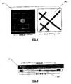
- FIG. 6A is a plan, frontal view of an embodiment of an encapsulated RFID tag 600 having an art image 604.
- FIG. 6B is a plan, frontal view of an alternative embodiment of an encapsulated RFID tag 602 having an art image 606.
- Other embodiments may have omitted the art image or may be in other configurations.
- FIG. 7 is an exemplary illustration of two examples of an encapsulated RFID tag 702 mounted on a mirror 704 of a vehicle.
- information about the location of the vehicle, its cargo, ownership, identity, existence, etc. may be programmed into the RFID tag or received by one or more appropriately-placed RFID readers in response to an interrogation signal.
- an RFID device is mounted inside a mirror 704 of a vehicle. Such a mounting will help protect the RFID device from environmental exposure, damage and theft. It will also conceal the RFID device.
- One method of mounting an RFID device in a vehicle mirror 704 is by removing the neoprene, rubber, or other sealing material that surrounds the mirror from its body or head, placing the RFID device within the body or head such that it will not interfere with the replacement of the mirror or be damaged by moving parts within the head, and replace the mirror and its sealing material. In other mirror types, other methods may be used to place an RFID device within the body of the mirror.
- the embodiments of this invention provide encapsulating materials that are comprised of materials such that interference or impediment of RF signals transmitted to or from the encapsulated RFID device is minimized or non-existent. Furthermore, if the encapsulated RFID device is to be placed on or near a ferrous surface, or other material that tends to detrimentally affect RF transmissions, the space between the encapsulated RFID device and the RF resistant materials caused by the encapsulating material tends to improve the transmission and reception properties for the RFID device. In other embodiments, a stand-off bracket is used to further separate the RFID device from RF resistant materials.
- FIGS. 8A-8D illustrate embodiments of a stand-off bracket for use with an RFID device.
- FIG. 8A is a plan view of an embodiment of an RFID device assembly 800 comprised of a stand-off bracket 802 for an RFID device and an exemplary encapsulated RFID device 804 mounted thereon. Section A-A of FIG. 8A is illustrated in FIG. 8C .
- the bracket 802 is comprised of one or more materials such as, for example, injection molded plastic, paper (e.g., cardboard), corrugated plastic, etc., that have minimal adverse effect on RF signals that travel to and from the RFID device 804. As shown in FIG.
- the bracket 802 has a first surface 812 for mounting or setting on a mounting or support surface and a second surface 810 on which the RFID device is attached or placed.
- the first surface 812 may be glued, nailed, screwed, stapled, clamped or otherwise affixed to the mounting surface, or it may be held in place merely by friction or gravity.
- the second surface 810 is elevated a distance from the first surface 812 such that the RFID device 804 is held a distance, d, from the mounting surface to which the bracket is attached or placed, as shown in FIG. 8C .
- the space 808 between the bottom of the second surface 810 and the mounting surface 812 is hollow, although in other embodiments the space 808 may be filled or partially filled with one or more materials that are RF permeable, or with the same material that comprises the bracket 802.
- the stand-off bracket 802 allows RF signals to travel in the space between the mounting surface and the RFID device 804 , thus enabling better transmission and reception of RF signals by the RFID device 804.
- FIG. 8B is a plan view of an embodiment of a stand-off bracket 802. This embodiment is illustrated not having an RFID device mounted thereon. Section B-B of the embodiment of FIG. 8B is illustrated in FIG. 8D .
- FIG. 8C is a cross-sectional view of an embodiment of a stand-off bracket assembly 800 having an exemplary encapsulated RFID device 804 mounted thereon.
- FIG. 8C illustrates Section A-A of FIG. 8A .
- the RFID device 804 is shown mounted on the upper surface 810 of the stand-off bracket 802 , thus providing a distance, d, between the RFID device 804 and any mounting surface.
- the first surface 812 is for mounting or setting the stand-off bracket 802 on a mounting support surface.
- FIG. 8D is a cross-sectional view of an embodiment of a stand-off bracket assembly 800 without an RFID device mounted thereon.
- FIG. 8D illustrates Section B-B of FIG. 8B .
- the stand-off bracket 802 shown in FIGS. 8A-8D are square, this is for exemplary purposes only. In other embodiments, not shown, the stand-off bracket may be rectangular, circular, oval, triangular, spherical, hemispherical, or any other shape that will provide a separation between the mounted RFID device and the mounting surface.
- FIG. 9 is a side view of an embodiment of a domed encapsulated RFID tag 900 that may be mounted on a stand-off bracket 802.
- One particular embodiment of the domed, encapsulated RFID tag 900 utilizes an ISO 18000-6 compliant RFID device, as they are known in the art, though other RFID devices (e.g., EPC compliant) may be used.
- the RFID tag 900 of the embodiment of FIG. 9 is comprised of four layers, although in other embodiments more or fewer layers may be present.
- the layers of the RFID tag 900 of FIG. 9 are comprised of an adhesive layer 908 , an RFID device 906 , an art image layer 904 , and an encapsulating material layer 902. These various layers have previously been described herein.
- the RFID tag 900 may be affixed to the upper surface 810 of a stand-off bracket 802 to provide separation from the RFID tag 900 and the mounting surface for better RF transmission and reception.
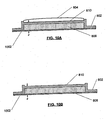
- FIG. 10A is a cross-sectional view of an embodiment of a stand-off bracket 802 for an RFID device having an exemplary encapsulated RFID tag 804 mounted thereon and having an adhesive layer 1002 for mounting.
- the adhesive layer is affixed to the first surface 812 of the stand-off bracket 802. At least one outer surface of the adhesive layer is comprised of an adhesive material that may be used to adhere the stand-off bracket 802 to a mounting surface.
- the adhesive layer 1002 also increases the separation between the mounting surface and the top surface 810 of the stand-off bracket 802 , where an RFID device may be mounted.
- FIG. 10B is another cross-sectional view of an embodiment of a stand-off bracket for an RFID device.
- an RFID device is not mounted on the stand-off bracket 802 ; however, the stand-off bracket 802 is further comprised of an adhesive layer 1002 for mounting.
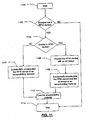
- FIG. 11 depicts a flow chart of a method of encapsulating and overlaying an RFID device.
- the process starts at step 1100 .
- a decision is made whether to encapsulate an RFID device. If at step 1102 the answer is NO, then the process continues to step 1114 where the process ends. If at step 1102 the answer is YES, the process proceeds to step 1104 where a decision is made whether to overlay an RFID device. If at step 1104 the answer is NO, the process continues to step 1110 where the RFID device is substantially encapsulated in an encapsulating material. The encapsulating material is then cured at step 1112. The process continues to step 1114 where it ends.
- step 1104 the process continues to step 1106 where the RFID device is overlaid with an art image layer.
- step 1108 the RFID and art image are substantially encapsulated in an encapsulating material.
- step 1112 the encapsulating material is cured.
- step 1114 it ends.
- FIG. 12A depicts a flow chart of a method of fabricating an encapsulated RFID tag.
- the process begins at step 1200.
- the process continues to step 1202 where a viscous encapsulating material is placed on at least one surface of an RFID device.
- the process continues to step 1204 where the encapsulating material is cured to a non-viscous state.
- the process then ends at step 1206.
- FIG. 12B depicts a flow chart of a method of fabricating an encapsulated RFID tag by overlaying an RFID tag with an art image and encapsulating the RFID device and art image.
- the process beings at step 1210 .
- the process continues to step 1212 where at least one surface of an RFID device is overlaid with an art image.
- the process continues to step 1214 where a viscous encapsulating material is placed on at least one surface of the RFID device and art image.
- the encapsulating material is cured to a non-viscous state in step 1216 .
- the process then ends at step 1218 .
Description
- The present invention relates generally to radio frequency identification (RFID) devices and, more particularly, to the encapsulation and mounting of RFID devices. Specifically, the present invention relates to the domed encapsulation of RFID transponders and their mounting on surfaces that impede radio frequency (RF) transmissions.
- Radio frequency identification (RFID) is an information acquisition technology. RFID systems are generally designed to manage assets of many types. RFID systems are generally comprised of transponders (a/k/a "tags"), a transmitter to provide energy to the tags, a receiver to receive transmissions from the transponders, and a computer system to process the received information. The transmitter and receiver may be combined into a single device often referred to as an interrogator or reader. Typically a small RFID tag is attached to the asset so that either the asset's presence at a certain location can be detected or the asset can be identified by the response of the tag to the interrogation either by hand-held interrogators or fixed-site interrogators that are encountered in the course of asset movement. The failure to detect an expected RFID signal may also be used as an indicator.
- RFID transponders may be exposed to a variety of harsh environments during the course of their use. For this reason, tags must be tolerant of many hostile chemicals, abrasives, weather conditions and mechanical stresses. Although RFID devices generally are packaged in a plastic housing, these housings may lack sufficient properties to withstand harsh environments for prolonged periods.
- Encapsulation of art images and advertising materials is a well-known process in the formation of domed labels. A process known as "domed encapsulation" provides an encapsulating material over a substrate on which artwork or advertising is placed. Generally, the encapsulating material is translucent, though in some instances it may be colored, tinted, or otherwise opaque. The encapsulating material makes the underlying art or advertisement stand out with a three-dimensional "wet" look and protects the artwork. Generally, the encapsulating material is comprised of an epoxy for an application where flexibility is not a requirement, or polyurethane where more flexibility is needed.
- Generally, the doming process depends on surface tension to form a bubble of the encapsulating material on an item being decorated without going off the edge of the item. The encapsulating material is applied to the substrate and, if required, then exposed to a hardening or curing process, such as exposure to ultra-violet light or heat. Known uses of the encapsulating process are the creation of identification, advertising and artwork used on automobiles, computers and computer cases, name badges and lapel pins.
- RFID devices are commonly used on or near a number of surface materials.
- Some of these surfaces that are comprised of materials such as, for example, various metals, impede or block the transmission and reception of radio frequency (RF) signals by the RFID devices. In other instances, materials proximate to the surface on which the RFID device is mounted may impede the transmission and reception of RF signals by the RFID device. An example would be a glass or plastic container holding a fluid that interferes with the transmission and reception of RF signals by an RFID device mounted on or within the container.
- Therefore, a method and apparatus are needed to overcome challenges associated with the use of RFID devices, some of which are given above, including protecting RFID devices through encapsulation, overlaying the devices with images, and mounting the devices so that their reception and transmission of RF signals is not impeded.
-
WO 96/08596 -
EP0772152 discloses a chip carrier with a cover which can be permanently clipped to the carrier. The cover and the chip carrier enclose the chip. A fastener is formed on the chip carrier to non-releasably fasten the chip carrier to containers of different geometric dimensions. - To overcome many of the challenges encountered in the art, the invention provides a RFID tag according to claim 1 and a method of encapsulation according to claim 9.
- According to one embodiment of the invention, an RFID device such as, for example, an RFID transponder, is encapsulated by known domed encapsulation techniques to conceal the RFID device and form a protected RFID device for use in harsh environments. Furthermore, the embodiments of this invention provide a domed encapsulated RFID apparatus and method of forming the same, such that interference, attenuation and absorption ,of the radio frequency (RF) signal by the encapsulating material and by any surface on which the encapsulated RFID device is placed is minimized.
- The packaging of RFID devices performs several functions, including environmental protection and concealment. However, the packaging material should be compatible with the RF performance of the tag to avoid degradation of the performance of the RFID system. The present invention involves encapsulating a standard RFID tag in a manner that will protect or conceal the RFID tag. Because of its use in artwork and labeling, domed encapsulation is relatively inexpensive. An economical way to encapsulate an RFID device is by using a domed polyester or polyurethane process.
- In one embodiment of the invention, a spacing device holds an RFID device a distance away from a mounting surface so that RF interference caused by the mounting surface or nearby materials is lessened.
- In one embodiment, an art image such as a logo, trademark slogan, etc. is encapsulated with the RFID tag. In addition, one or more surfaces of the encapsulated RFID tag may comprise an adhesive material to facilitate mounting of the encapsulated RFID tag on a body.
- A particular use of the invention is to track shipments, for example by being attached to a tractor or a trailer.
- An advantage of the invention is that the RFID device is concealed.
- The encapsulated RFID device of the invention may be used for one or more of a label, nametag, luggage tag, advertisement, key fob, emblem, automobile emblem, or decoration.
- The encapsulated RFID device may be comprised of one or more materials having certain thicknesses such that interference with RF signals is minimized.
- The invention may be used with a stand-off bracket configured to maintain an RFID device in the 860-928 MHz range a distance from a supporting surface.
- The bracket is useful on a surface or near a material that impedes or blocks RF transmission.
- The encapsulated RFID device may be mounted in the mirror assembly of a vehicle, or on a stand-off bracket within a mirror assembly of a vehicle.
- These and other aspects of the invention not provided above are more fully described herein.
- Having thus described the invention in general terms, reference will now be made to the accompanying drawings, which are not necessarily drawn to scale, and wherein:
-
FIG. 1A is an exploded view of the components that comprise an exemplary domed encapsulated RFID tag in an embodiment of the invention; -
FIG. 1B is an exploded view of the components that comprise an exemplary domed encapsulated RFID tag in another embodiment of the invention; -
FIG. 1C is an exploded view of the components that comprise an exemplary domed encapsulated RFID tag in another embodiment of the invention; -
FIG. 1D is an exploded view of the components that comprise an exemplary domed encapsulated RFID tag in another embodiment of the invention; -
FIG. 2A is an exploded view of the components that comprise an exemplary domed encapsulated RFID tag in an embodiment of the invention having a base substrate; -
FIG. 2B is an exploded view of the components that comprise an exemplary domed encapsulated RFID tag in another embodiment of the invention having a base substrate; -
FIG. 3 is an image of the manufacture of an exemplary domed encapsulated RFID tag, wherein the liquid encapsulating material is being placed on the base substrate, RFID device and art image; -
FIG. 4 illustrates an exemplary art image that may overlay an RFID device in an embodiment of the invention; -
FIG. 5 illustrates another exemplary art image that may overlay another embodiment of an RFID device in an embodiment of the invention; -
FIG. 6A is a plan view of an exemplary encapsulated RFID tag having an art image, in an embodiment of the invention; -
FIG. 6B is a plan view of an exemplary encapsulated RFID tag having an art image, in another embodiment of the invention; -
FIG. 7 is an exemplary illustration of two examples of an encapsulated RFID tag mounted on mirrors of a vehicle; -
FIG. 8A is a plan view of an embodiment of a stand-off bracket for an RFID device having an exemplary encapsulated RFID device mounted thereon; -
FIG. 8B is a plan view of an embodiment of a stand-off bracket of an RFID device not having an RFID device mounted thereon; -
FIG. 8C is a cross-sectional view of an embodiment of a stand-off bracket for an RFID device having an exemplary encapsulated RFID device mounted thereon; -
FIG. 8D is a cross-sectional view of an embodiment of a stand-off bracket for an RFID device not having an RFID device mounted thereon; -
FIG. 9 is a side view of an embodiment of an encapsulated RFID device;FIG. 10A is a cross-sectional view of an embodiment of a stand-off bracket for an RFID device having an exemplary encapsulated RFID device mounted thereon and having an adhesive layer for mounting; -
FIG. 10B is a cross-sectional view of an embodiment of a stand-off bracket for an RFID device not having an RFID device mounted thereon but having an adhesive layer for mounting; -
FIG. 11 depicts a flow chart of a method of encapsulating and overlaying an RFID device; -
FIG. 12A depicts a flow chart of a method of fabricating an encapsulated RFID tag; and -
FIG. 12B depicts a flow chart of a method of fabricating an encapsulated RFID tag by overlaying an RFID tag with an art image and encapsulating the RFID device and art image. - The present invention now will be described more fully hereinafter with reference to the accompanying drawings, in which some, but not all, embodiments of the invention are shown. Indeed, this invention may be embodied in many different forms and should not be construed as limited to the embodiments set forth herein; rather, these embodiments are provided so that this disclosure will satisfy applicable legal requirements. Like numbers refer to like elements throughout.
-
FIG. 1A is an exploded view of the components that comprise an exemplary domed encapsulatedRFID tag 100 in an embodiment of the invention. In this embodiment, anadhesive layer 102 comprised of an approximately 2 millimeter (mil) thick acrylic adhesive liner is substantially attached to and underlies anRFID device 104, though other thicknesses and types of adhesive may be used. In one embodiment, thisadhesive layer 102 has an adhesive on its exposed surface such that it can be adhesively mounted to another surface and an adhesive on the surface that is substantially in contact with theRFID device 104 such that theadhesive layer 102 is adhered to theRFID device 104. In various embodiments, theadhesive layer 102 may be dimensioned such that it extends beyond each edge of theRFID device 104 when the adhesive layer is substantially adhered to theRFID device 104, theadhesive layer 102 may be of the same dimensions as theRFID device 104 to which it is substantially adhered, or theadhesive layer 102 may be of smaller dimensions than theRFID device 104 to which it is substantially adhered. - In the particular embodiment of
FIG. 1 , animage layer 106 comprised of an approximately 2.4-mil thick polyester image layer substantially lies over theRFID device 104, although in other embodiments theimage layer 106 may lie substantially underneath theRFID device 104, or be composed of different materials and/or thicknesses. At least one surface of theimage layer 106 is substantially adhered to theRFID device 104. If theimage layer 106 substantially lies underneath theRFID device 104, one surface of theimage layer 106 is adhered to theRFID device 104 and a second surface of theimage layer 106 is substantially adhered to theadhesive layer 102. If the image layer substantially lies over theRFID device 104, one surface of the image layer is adhered to theRFID device 104 and a second surface of theimage layer 106 is substantially adhered to adome layer 108. Thedome layer 108 such as, for example, a clear, flexible, polyurethane dome, is placed over theimage layer 106 or, if theimage layer 106 is omitted or lies substantially underneath theRFID device 104, thedome layer 108 is placed over theRFID device 104. If theadhesive layer 102 is dimensioned such that it extends beyond any dimension of theRFID device 104, then thedome layer 108 may be in contact with theadhesive layer 102, thereby encapsulating theRFID device 104. In other embodiments, thedome layer 108 may be of the same dimensions as theunderlying RFID device 104, or the dome layer may have smaller dimensions than the RFID device. TheRFID device 104 is substantially sealed from atmospheric exposure, protected, or concealed by the encapsulation. -
FIG. 1B is another embodiment of the encapsulated RFID device shown inFIG. 1A . In the embodiment ofFIG. 1B , the encapsulatedRFID device 110 is comprised of anadhesive layer 112, anRFID device 114, and adome layer 116. The image layer is omitted from this embodiment, as compared to the embodiment ofFIG. 1A . -
FIG. 1C is yet another embodiment of the encapsulated RFID device shown inFIG. 1A . In the embodiment ofFIG. 1C , the encapsulatedRFID device 118 is comprised of anRFID device 120, animage layer 122, and adome layer 124. The adhesive layer is omitted from this embodiment, as compared to the embodiment ofFIG. 1A . -
FIG. 1D is another embodiment of the encapsulated RFID device shown inFIG. 1A . In the embodiment ofFIG. 1D , the encapsulated RFID device 126 is comprised of anRFID device 128 and adome layer 130. The adhesive layer and the image layer are each omitted from this embodiment, as compared to the embodiment ofFIG. 1A . - In another embodiment of the invention, as shown in the exploded view of
FIG. 2A , an exemplary domed, encapsulatedRFID tag 200 is comprised of asubstrate layer 202, anRFID device 204, anart image 206, and adome layer 208. In this embodiment, thesubstrate layer 202 may be comprised of a flexible, rigid, or semi-rigid material such as, for example, plastics, ferrous or non-ferrous metals, ceramics, composites, alloys, etc. Thesubstrate layer 202 may have an adhesive on its exposed surface to attach the encapsulatedRFID tag 200 to another surface. In some embodiments, thesubstrate layer 202 may have attached or embedded magnets to affix the encapsulatedRFID tag 200 to a surface containing magnetic material. In other embodiments, thesubstrate layer 202 itself may be magnetized, thus making it capable of being affixed to a surface containing magnetic material. In yet other embodiments, thesubstrate layer 202 may have other means of attachment to another surface such as a pin or clasp for attaching to an article of apparel, a split ring, lanyard, snap, buckle, screw, clamp, etc. AnRFID device 204 is substantially affixed to thesubstrate layer 202. In one embodiment, theRFID device 204 is substantially adhered to thesubstrate layer 202; however, in other embodiments theRFID device 204 may be clamped, screwed, welded, nailed, stapled, sewn, magnetically-held, or otherwise affixed to thesubstrate layer 202. - The
RFID device 204 is substantially encapsulated in an encapsulatingmaterial 208, thereby providing protection to theRFID device 204 and, in some instances, concealing theRFID device 204. In one embodiment, anart image 206 such as, for example, a corporation or other form of entity's logo or trademark, overlays theRFID device 204 and is substantially encapsulated in the encapsulatingmaterial 208 along with theRFID device 204. -
FIG. 2B is an exploded view of the components that comprise an exemplary domed encapsulatedRFID tag 210 in another embodiment of the invention having abase substrate 212. In this embodiment, the encapsulatedRFID tag 210 is comprised of abase substrate 212, anRFID device 214, and an encapsulatingmaterial 216. As compared to the embodiment shown inFIG. 2A ,FIG. 2B illustrates an embodiment of an encapsulatedRFID tag 210 wherein the art image layer is omitted. -
FIG. 3 is an image of a manufacturing process for an exemplary domed encapsulated RFID tag, wherein aliquid encapsulating material 302 is placed on asubstrate 304 comprised of an RFID device and art image. The encapsulatingmaterial 302 is see through, and may be a dark or colored substance. The encapsulatingmaterial 302 may be comprised of polyurethane, epoxy, acrylics or other suitable resins or materials such as, for example, polyethylene, polypropylene, polystyrene, polyester, etc. Generally, the encapsulatingmaterial 302 is comprised of an epoxy for an application where flexibility is not a requirement or polyurethane where more flexibility is needed. The doming process depends on surface tension to form a bubble of the encapsulatingmaterial 302 on an item being decorated without going off the edge of the item. The encapsulatingmaterial 302 is applied to thesubstrate 304 and, if required, then exposed to a hardening or curing process, such as exposure to ultra-violet light or heat. -
FIG. 4 illustrates an exemplaryart image layer 402 that may overlay anRFID device 404 in an embodiment of the invention. In one embodiment, theart image layer 402 is comprised of an approximately 2.4-mil polyester image substrate, though other thicknesses and materials may be used. The actual image 406 on theart image layer 402 may be silk-screened, painted, drawn, stamped, embedded or otherwise placed on or within theart image layer 402. In other embodiments, theart image layer 402 is comprised of a three-dimensional emblem, novelty, insignia, etc. In embodiments of the invention having anart image layer 402, the encapsulating material is generally translucent so that theart image layer 402 is substantially visible through the encapsulating material. -
FIG. 5 is an alternative exemplaryart image layer 502 that overlays analternate RFID device 504 in an embodiment of the invention, as compared to the embodiment shown inFIG. 4 . - The RFID device of the various embodiments of the invention may be, for example, an active or passive RFID transponder, as are commonly known in the art. The RFID device may be flexible, rigid, or semi-rigid. The RFID device may be contained within a housing, or it may rely upon the encapsulating material to provide a housing. In one embodiment, the RFID device is a flexible user-programmable RFID transponder such as those that are available from Alien Technologies Corp. of Morgan Hill, California; although other types of RFID devices manufactured by other manufacturers may be used. Other manufacturers of RFID devices include but are not limited to: Matrics, Inc. of Columbia Maryland; Phillips Electronics of Eindhoven, The Netherlands; and Texas Instruments Incorporated of Dallas, Texas. In one embodiment, the RFID device is an Alien Technologies Class 1, electronic product code (EPC) transponder.
- The RFID device includes devices that comply with the International Organization for Standardization (ISO) 18000-6 standard, including but not limited to ISO 18000-6 types A and B. ISO 18000-6 covers the air interface for RFID tags operating at ultra high frequency (860 - 930 MHz). The RFID device also includes devices that comply with the other parts of the ISO 18000 standard (e.g., 18000-1, 18000-2, etc.), as such parts are approved and adopted. The ISO 18000-6 standard, and all variants (e.g., Type A and B, etc.), are incorporated in their entirety by reference and made a part hereof. The RFID device also includes devices that comply with Electronic Product Code (EPC) standards, specifications and guidelines as were initially developed by the Auto-ID Center, including but not limited to EPC classes 0-1. The EPC standards are also fully incorporated herein by reference and made a part hereof.
-
FIG. 6A is a plan, frontal view of an embodiment of an encapsulatedRFID tag 600 having anart image 604.FIG. 6B is a plan, frontal view of an alternative embodiment of an encapsulatedRFID tag 602 having anart image 606. Other embodiments (not shown) may have omitted the art image or may be in other configurations. -
FIG. 7 is an exemplary illustration of two examples of an encapsulatedRFID tag 702 mounted on amirror 704 of a vehicle. In a typical use of such an encapsulated RFID tag, information about the location of the vehicle, its cargo, ownership, identity, existence, etc. may be programmed into the RFID tag or received by one or more appropriately-placed RFID readers in response to an interrogation signal. - In yet another example (not shown), an RFID device is mounted inside a
mirror 704 of a vehicle. Such a mounting will help protect the RFID device from environmental exposure, damage and theft. It will also conceal the RFID device. One method of mounting an RFID device in avehicle mirror 704 is by removing the neoprene, rubber, or other sealing material that surrounds the mirror from its body or head, placing the RFID device within the body or head such that it will not interfere with the replacement of the mirror or be damaged by moving parts within the head, and replace the mirror and its sealing material. In other mirror types, other methods may be used to place an RFID device within the body of the mirror. - The embodiments of this invention provide encapsulating materials that are comprised of materials such that interference or impediment of RF signals transmitted to or from the encapsulated RFID device is minimized or non-existent. Furthermore, if the encapsulated RFID device is to be placed on or near a ferrous surface, or other material that tends to detrimentally affect RF transmissions, the space between the encapsulated RFID device and the RF resistant materials caused by the encapsulating material tends to improve the transmission and reception properties for the RFID device. In other embodiments, a stand-off bracket is used to further separate the RFID device from RF resistant materials.
-
FIGS. 8A-8D illustrate embodiments of a stand-off bracket for use with an RFID device.FIG. 8A is a plan view of an embodiment of anRFID device assembly 800 comprised of a stand-off bracket 802 for an RFID device and an exemplary encapsulatedRFID device 804 mounted thereon. Section A-A ofFIG. 8A is illustrated inFIG. 8C . Thebracket 802 is comprised of one or more materials such as, for example, injection molded plastic, paper (e.g., cardboard), corrugated plastic, etc., that have minimal adverse effect on RF signals that travel to and from theRFID device 804. As shown inFIG. 8C , thebracket 802 has afirst surface 812 for mounting or setting on a mounting or support surface and asecond surface 810 on which the RFID device is attached or placed. Thefirst surface 812 may be glued, nailed, screwed, stapled, clamped or otherwise affixed to the mounting surface, or it may be held in place merely by friction or gravity. Thesecond surface 810 is elevated a distance from thefirst surface 812 such that theRFID device 804 is held a distance, d, from the mounting surface to which the bracket is attached or placed, as shown inFIG. 8C . Generally, thespace 808 between the bottom of thesecond surface 810 and the mountingsurface 812 is hollow, although in other embodiments thespace 808 may be filled or partially filled with one or more materials that are RF permeable, or with the same material that comprises thebracket 802. The stand-off bracket 802 allows RF signals to travel in the space between the mounting surface and theRFID device 804, thus enabling better transmission and reception of RF signals by theRFID device 804. -
FIG. 8B is a plan view of an embodiment of a stand-off bracket 802. This embodiment is illustrated not having an RFID device mounted thereon. Section B-B of the embodiment ofFIG. 8B is illustrated inFIG. 8D . -
FIG. 8C is a cross-sectional view of an embodiment of a stand-off bracket assembly 800 having an exemplary encapsulatedRFID device 804 mounted thereon.FIG. 8C illustrates Section A-A ofFIG. 8A . TheRFID device 804 is shown mounted on theupper surface 810 of the stand-off bracket 802, thus providing a distance, d, between theRFID device 804 and any mounting surface. Thefirst surface 812 is for mounting or setting the stand-off bracket 802 on a mounting support surface.FIG. 8D is a cross-sectional view of an embodiment of a stand-off bracket assembly 800 without an RFID device mounted thereon.FIG. 8D illustrates Section B-B ofFIG. 8B . - Although the embodiments of the stand-
off bracket 802 shown inFIGS. 8A-8D are square, this is for exemplary purposes only. In other embodiments, not shown, the stand-off bracket may be rectangular, circular, oval, triangular, spherical, hemispherical, or any other shape that will provide a separation between the mounted RFID device and the mounting surface. -
FIG. 9 is a side view of an embodiment of a domed encapsulatedRFID tag 900 that may be mounted on a stand-off bracket 802. One particular embodiment of the domed, encapsulatedRFID tag 900 utilizes an ISO 18000-6 compliant RFID device, as they are known in the art, though other RFID devices (e.g., EPC compliant) may be used. TheRFID tag 900 of the embodiment ofFIG. 9 is comprised of four layers, although in other embodiments more or fewer layers may be present. The layers of theRFID tag 900 ofFIG. 9 are comprised of anadhesive layer 908, anRFID device 906, anart image layer 904, and an encapsulatingmaterial layer 902. These various layers have previously been described herein. TheRFID tag 900 may be affixed to theupper surface 810 of a stand-off bracket 802 to provide separation from theRFID tag 900 and the mounting surface for better RF transmission and reception. -
FIG. 10A is a cross-sectional view of an embodiment of a stand-off bracket 802 for an RFID device having an exemplary encapsulatedRFID tag 804 mounted thereon and having anadhesive layer 1002 for mounting. The adhesive layer is affixed to thefirst surface 812 of the stand-off bracket 802. At least one outer surface of the adhesive layer is comprised of an adhesive material that may be used to adhere the stand-off bracket 802 to a mounting surface. Theadhesive layer 1002 also increases the separation between the mounting surface and thetop surface 810 of the stand-off bracket 802, where an RFID device may be mounted. -
FIG. 10B is another cross-sectional view of an embodiment of a stand-off bracket for an RFID device. In this embodiment, an RFID device is not mounted on the stand-off bracket 802; however, the stand-off bracket 802 is further comprised of anadhesive layer 1002 for mounting. -
FIG. 11 depicts a flow chart of a method of encapsulating and overlaying an RFID device. The process starts atstep 1100. At step 1102 a decision is made whether to encapsulate an RFID device. If atstep 1102 the answer is NO, then the process continues to step 1114 where the process ends. If atstep 1102 the answer is YES, the process proceeds to step 1104 where a decision is made whether to overlay an RFID device. If atstep 1104 the answer is NO, the process continues to step 1110 where the RFID device is substantially encapsulated in an encapsulating material. The encapsulating material is then cured atstep 1112. The process continues to step 1114 where it ends. However, if atstep 1104 the answer is YES, the process continues to step 1106 where the RFID device is overlaid with an art image layer. The process continues to step 1108 where the RFID and art image are substantially encapsulated in an encapsulating material. The process continues to step 1112 where the encapsulating material is cured. The process continues to step 1114 where it ends. -
FIG. 12A depicts a flow chart of a method of fabricating an encapsulated RFID tag. The process begins atstep 1200. The process continues to step 1202 where a viscous encapsulating material is placed on at least one surface of an RFID device. The process continues to step 1204 where the encapsulating material is cured to a non-viscous state. The process then ends atstep 1206. -
FIG. 12B depicts a flow chart of a method of fabricating an encapsulated RFID tag by overlaying an RFID tag with an art image and encapsulating the RFID device and art image. The process beings atstep 1210. The process continues to step 1212 where at least one surface of an RFID device is overlaid with an art image. The process continues to step 1214 where a viscous encapsulating material is placed on at least one surface of the RFID device and art image. The encapsulating material is cured to a non-viscous state instep 1216. The process then ends atstep 1218. - Many modifications and other embodiments of the invention set forth herein will come to mind to one skilled in the art to which this invention pertains having the benefit of the teachings presented in the foregoing descriptions and the associated drawings. Therefore, it is to be understood that the invention is not to be limited to the specific embodiments disclosed and that modifications and other embodiments are intended to be included within the scope of the appended claims. Although specific terms are employed herein, they are used in a generic and descriptive sense only and not for purposes of limitation.
Claims (12)
- A domed encapsulated radio frequency identification ('RFID') tag (100) characterised in that the tag comprises:a substrate layer (102);an RFID tag layer (100) having a first side adhered to said substrate layer (102), and a second side;an art image layer (106) comprising an art image thereon, said layer having a first side substantially adhered to the second side of the RFID tag (100); and a second side; anda translucent encapsulating domed layer (108) substantially adhered to the second side of said art image layer (106);wherein said layers are single, continuous and unbroken, and the contact surfaces thereof are flat.
- The tag of claim 1, wherein the art image layer is comprised of polyester.
- The tag of claim 1 or claim 2, further comprising an adhesive layer for adhering said substrate to a surface.
- The tag of any preceding claim, wherein the adhesive layer is comprised of a 2mm acrylic adhesive layer.
- The tag of any preceding claim, wherein the material of the domed layer is selected from the group consisting of polyurethane, polyethylene, polypropylene, polystyrene, polyester, and epoxy, and combinations thereof
- The tag of any preceding claim, and comprising one or more of a label, nametag, luggage tag, advertisement, key fob, emblem, automobile emblem, and decoration.
- The tag of any preceding claim, wherein the RFID device is comprised of an RFID transponder.
- The tag of any preceding claim, wherein the art image layer is comprised of a 2.4 millimeter thick image substrate comprised of polyester.
- A method of encapsulating an RFID device layer, an art image on an art image layer, and a substrate layer to form a domed, encapsulated RFID tag, characterised in that said method comprises the steps of:substantially encapsulating the RFID device layer, the art image layer, and the substrate layer in a single continuous viscous layer of translucent encapsulating material having a domed shape, wherein said RFID device layer has a first side affixed to a second side of said substrate layer and a second side affixed to a first side of said art image layer, said art image layer comprises a single continuous layer and has a preprinted art image, the substrate layer comprises a single continuous layer, said art image layer has a second side affixed to said encapsulating material, said substrate layer, said RFID device layer, and said art image layer are unbroken layers and the contact surfaces of said layers are flat; andcuring said encapsulating material to form a domed, encapsulated RFID tag.
- The method of claim 9, wherein substantially encapsulating the RFID device layer comprises using an encapsulating material selected from the group consisting of polyurethane, polyethylene, polypropylene, polystyrene, polyester, an epoxy, and combinations thereof.
- The method of claim 9 or claim 10, further comprising the steps of:overlaying the RFID device layer with an art image layer; andsubstantially encapsulating the RFID device layer and the art image layer in said encapsulating material.
- The method of claim 11, wherein overlaying the RFID device layer with the art image layer comprises using an art image layer comprised of a 2.4 millimeter thick image substrate comprised of polyester.
Applications Claiming Priority (4)
| Application Number | Priority Date | Filing Date | Title |
|---|---|---|---|
| US54050804P | 2004-01-30 | 2004-01-30 | |
| US54445504P | 2004-02-13 | 2004-02-13 | |
| US10/972,827 US7405656B2 (en) | 2004-01-30 | 2004-10-25 | Device and method for encapsulation and mounting of RFID devices |
| PCT/US2004/043919 WO2005076207A2 (en) | 2004-01-30 | 2004-12-30 | Device and method for encapsulation and mounting of rfid devices |
Publications (2)
| Publication Number | Publication Date |
|---|---|
| EP1714239A2 EP1714239A2 (en) | 2006-10-25 |
| EP1714239B1 true EP1714239B1 (en) | 2015-09-23 |
Family
ID=34831207
Family Applications (1)
| Application Number | Title | Priority Date | Filing Date |
|---|---|---|---|
| EP04815909.9A Active EP1714239B1 (en) | 2004-01-30 | 2004-12-30 | Device and method for encapsulation and mounting of rfid devices |
Country Status (4)
| Country | Link |
|---|---|
| US (1) | US7405656B2 (en) |
| EP (1) | EP1714239B1 (en) |
| CA (1) | CA2555000C (en) |
| WO (1) | WO2005076207A2 (en) |
Cited By (1)
| Publication number | Priority date | Publication date | Assignee | Title |
|---|---|---|---|---|
| DE102019110509A1 (en) * | 2019-04-23 | 2020-10-29 | Aeg Identifikationssysteme Gmbh | Passive radio transmission device |
Families Citing this family (45)
| Publication number | Priority date | Publication date | Assignee | Title |
|---|---|---|---|---|
| US7958715B2 (en) * | 2003-03-13 | 2011-06-14 | National Oilwell Varco, L.P. | Chain with identification apparatus |
| US7946356B2 (en) * | 2004-04-15 | 2011-05-24 | National Oilwell Varco L.P. | Systems and methods for monitored drilling |
| US9784041B2 (en) * | 2004-04-15 | 2017-10-10 | National Oilwell Varco L.P. | Drilling rig riser identification apparatus |
| US7817014B2 (en) * | 2004-07-30 | 2010-10-19 | Reva Systems Corporation | Scheduling in an RFID system having a coordinated RFID tag reader array |
| EP1799610B1 (en) * | 2004-09-24 | 2012-11-21 | Colder Products Company | Coupler with radio frequency identification tag |
| JP2006209497A (en) * | 2005-01-28 | 2006-08-10 | Seiko Epson Corp | Rfid tag, print sheet, printer device and rfid system |
| US7898391B2 (en) * | 2005-07-01 | 2011-03-01 | Trimble Navigation Limited | Multi-reader coordination in RFID system |
| DE102005031579A1 (en) * | 2005-07-06 | 2007-01-11 | Bayer Technology Services Gmbh | Fasteners for transponders for the identification of metallic or metal-containing objects via radio-based transponder technology (RFID) |
| JP2007022467A (en) * | 2005-07-20 | 2007-02-01 | Honda Motor Co Ltd | Illegal alteration detection system for vehicle parts |
| US20070139202A1 (en) * | 2005-12-21 | 2007-06-21 | Symbol Technologies, Inc. | Radio frequency identification (RFID) solution to lost time spent on instrument inventory |
| US20070159337A1 (en) * | 2006-01-12 | 2007-07-12 | Sdgi Holdings, Inc. | Modular RFID tag |
| US20070197299A1 (en) * | 2006-02-14 | 2007-08-23 | Ubi-Trak | Secure Gaming Chip |
| JP2007286757A (en) * | 2006-04-13 | 2007-11-01 | Brother Ind Ltd | Radio tag label, tag tape roll, and radio tag circuit element cartridge |
| JP4040661B2 (en) * | 2006-05-01 | 2008-01-30 | 株式会社神戸製鋼所 | RFID tag mounting structure and detection method |
| GB0610634D0 (en) | 2006-05-30 | 2006-07-05 | Dow Corning | Insulating glass unit |
| US7963452B2 (en) * | 2006-09-11 | 2011-06-21 | National Oilwell Varco, L.P. | RFID tag assembly |
| US7760099B2 (en) * | 2006-11-03 | 2010-07-20 | Codan Us Corporation | Radio frequency verification system and device |
| DE102007026155A1 (en) * | 2007-06-04 | 2009-01-08 | Fraunhofer-Gesellschaft zur Förderung der angewandten Forschung e.V. | Method for recording process parameters and wood-based product |
| US8947207B2 (en) | 2008-04-29 | 2015-02-03 | Quake Global, Inc. | Method and apparatus for a deployable radio-frequency identification portal system |
| WO2009157747A1 (en) * | 2008-06-23 | 2009-12-30 | RFID Mexico, S.A. DE C.V. | Rfid tag encapsulation structure |
| US8068028B2 (en) * | 2008-09-26 | 2011-11-29 | Avery Dennison Corporation | Encapsulated RFID device for flexible, non-planar or curvilinear surfaces |
| US9841492B2 (en) | 2013-02-25 | 2017-12-12 | Quake Global, Inc. | Ceiling-mounted RFID-enabled tracking |
| MX359877B (en) | 2013-02-26 | 2018-10-15 | Quake Global Inc | Methods and apparatus for automatic identification wristband. |
| CN105874886B (en) | 2014-01-02 | 2019-02-19 | 飞利浦照明控股有限公司 | Electronic equipment, LED light and manufacturing method |
| US9449295B2 (en) | 2014-06-25 | 2016-09-20 | Amazon Technologies, Inc. | Tracking transactions by confluences and sequences of RFID signals |
| US10649497B2 (en) * | 2014-07-23 | 2020-05-12 | Apple Inc. | Adaptive processes for improving integrity of surfaces |
| US10289947B2 (en) | 2016-07-12 | 2019-05-14 | Parker-Hannifin Corporation | Impact RFID tag |
| US10819137B2 (en) | 2016-12-14 | 2020-10-27 | Ajay Khoche | Energy harvesting wireless sensing system |
| US10902310B2 (en) | 2016-12-14 | 2021-01-26 | Trackonomy Systems, Inc. | Wireless communications and transducer based event detection platform |
| US10262255B2 (en) | 2016-12-14 | 2019-04-16 | Trackonomy Systems, Inc. | Multifunction adhesive product for ubiquitous realtime tracking |
| US10885420B2 (en) | 2016-12-14 | 2021-01-05 | Ajay Khoche | Package sealing tape types with varied transducer sampling densities |
| US11295190B2 (en) | 2016-12-14 | 2022-04-05 | Hendrik J Volkerink | Correlated asset identifier association |
| US11138490B2 (en) | 2016-12-14 | 2021-10-05 | Ajay Khoche | Hierarchical combination of distributed statistics in a monitoring network |
| US11055597B2 (en) * | 2017-10-13 | 2021-07-06 | Magnum Magnetics Corporation | RFID magnet and method of making |
| EP3724818A4 (en) * | 2017-12-14 | 2021-10-27 | Trackonomy Systems, Inc. | Flexible adhesive tape platform for wireless transducing circuits and applications |
| US11308370B2 (en) | 2019-04-04 | 2022-04-19 | Trackonomy Systems, Inc. | Correlating asset identifiers |
| WO2020247354A1 (en) | 2019-06-05 | 2020-12-10 | Trackonomy Systems, Inc. | Temperature monitoring in cold supply chains |
| WO2021051087A1 (en) | 2019-09-13 | 2021-03-18 | Trackonomy Systems, Inc. | Roll-to-roll additive manufacturing method and device |
| US11612226B1 (en) | 2019-09-25 | 2023-03-28 | Apple Inc. | Cases for electronic devices |
| US11587425B1 (en) | 2020-05-17 | 2023-02-21 | Trackonomy Systems, Inc. | Next generation building access control, indoor locationing, and interaction tracking |
| US11864058B1 (en) | 2020-10-04 | 2024-01-02 | Trackonomy Systems, Inc. | Flexible tracking device for cables and equipment |
| EP4186053A1 (en) | 2020-07-24 | 2023-05-31 | Trackonomy Systems, Inc. | Tearing to turn on wireless node with multiple cutouts for re-use |
| US11527148B1 (en) | 2020-10-04 | 2022-12-13 | Trackonomy Systems, Inc. | Augmented reality for guiding users to assets in IOT applications |
| US11819305B1 (en) | 2020-10-05 | 2023-11-21 | Trackonomy Systems, Inc. | Method for determining direction of movement through gates and system thereof |
| US11869994B2 (en) | 2020-12-12 | 2024-01-09 | Trackonomy Systems, Inc. | Flexible solar-powered wireless communication device |
Citations (2)
| Publication number | Priority date | Publication date | Assignee | Title |
|---|---|---|---|---|
| GB2115774A (en) * | 1982-03-01 | 1983-09-14 | John David Trueman | Tag |
| DE19721058A1 (en) * | 1997-05-20 | 1998-11-26 | Giesecke & Devrient Gmbh | Injection molded card with decorative layer |
Family Cites Families (25)
| Publication number | Priority date | Publication date | Assignee | Title |
|---|---|---|---|---|
| US5682143A (en) * | 1994-09-09 | 1997-10-28 | International Business Machines Corporation | Radio frequency identification tag |
| US5528222A (en) * | 1994-09-09 | 1996-06-18 | International Business Machines Corporation | Radio frequency circuit and memory in thin flexible package |
| GB9418386D0 (en) | 1994-09-13 | 1994-11-02 | Polymark Uk Limited | Labelling laundry items |
| US5477219A (en) * | 1995-03-30 | 1995-12-19 | Minnesota Mining And Manufacturing Company | Composite electronic article surveillance, identification, and security marker assembly and system |
| US5880675A (en) | 1995-05-19 | 1999-03-09 | Texas Instruments Incorporated | Reusable package for identification devices |
| DE19540595A1 (en) | 1995-10-31 | 1997-05-07 | Messer Griesheim Gmbh | Plastic chip carrier |
| US5988510A (en) * | 1997-02-13 | 1999-11-23 | Micron Communications, Inc. | Tamper resistant smart card and method of protecting data in a smart card |
| US6339385B1 (en) * | 1997-08-20 | 2002-01-15 | Micron Technology, Inc. | Electronic communication devices, methods of forming electrical communication devices, and communication methods |
| US6052062A (en) * | 1997-08-20 | 2000-04-18 | Micron Technology, Inc. | Cards, communication devices, and methods of forming and encoding visibly perceptible information on the same |
| US6089458A (en) * | 1997-10-17 | 2000-07-18 | Micron Technology, Inc. | Method of processing liquids, epoxy fabrication method, method of fabricating a radio frequency intelligent communication device, and method involving a mixture of different liquids |
| DE69938929D1 (en) * | 1998-09-11 | 2008-07-31 | Motorola Inc | RFID LABELING DEVICE AND METHOD |
| US6100804A (en) * | 1998-10-29 | 2000-08-08 | Intecmec Ip Corp. | Radio frequency identification system |
| US6262692B1 (en) * | 1999-01-13 | 2001-07-17 | Brady Worldwide, Inc. | Laminate RFID label and method of manufacture |
| US6421013B1 (en) * | 1999-10-04 | 2002-07-16 | Amerasia International Technology, Inc. | Tamper-resistant wireless article including an antenna |
| US6518885B1 (en) * | 1999-10-14 | 2003-02-11 | Intermec Ip Corp. | Ultra-thin outline package for integrated circuit |
| US6369711B1 (en) * | 2000-06-09 | 2002-04-09 | Intermec Ip Corp | Profile corrected label with RFID transponder and method for making same |
| US6592043B1 (en) * | 2000-08-17 | 2003-07-15 | Rick A. Britton | Fixture to mount a miniature proximity transponder to another article |
| DE10056473C1 (en) | 2000-11-15 | 2002-01-17 | Infineon Technologies Ag | Transponder for metallic object has rigid body formed as screw with IC chip in threaded bolt coupled to antenna in screw head |
| US6758000B2 (en) * | 2001-01-10 | 2004-07-06 | Avery Dennison Corporation | Livestock security tag assembly |
| US6951596B2 (en) * | 2002-01-18 | 2005-10-04 | Avery Dennison Corporation | RFID label technique |
| DE10113921B4 (en) | 2001-03-21 | 2012-04-12 | Identa Ausweissysteme Gmbh | Method for producing an identity card |
| ATE414969T1 (en) | 2001-03-28 | 2008-12-15 | Latschbacher Gmbh | SIGNING ELEMENT FOR MARKING WOOD, ESPECIALLY TREE TRUNKS |
| EP1286325B1 (en) * | 2001-08-14 | 2004-10-13 | Latschbacher GmbH | Identification marking tag for wood, in particular for tree trunks |
| WO2005032016A2 (en) * | 2003-09-24 | 2005-04-07 | United Parcel Service Of America, Inc. | Rapid exchange mounting system for testing wireless networks |
| USD555468S1 (en) * | 2007-03-28 | 2007-11-20 | United Parcel Service Of America, Inc. | Combination mounting bracket and support tray |
-
2004
- 2004-10-25 US US10/972,827 patent/US7405656B2/en active Active
- 2004-12-30 CA CA2555000A patent/CA2555000C/en active Active
- 2004-12-30 WO PCT/US2004/043919 patent/WO2005076207A2/en active Application Filing
- 2004-12-30 EP EP04815909.9A patent/EP1714239B1/en active Active
Patent Citations (2)
| Publication number | Priority date | Publication date | Assignee | Title |
|---|---|---|---|---|
| GB2115774A (en) * | 1982-03-01 | 1983-09-14 | John David Trueman | Tag |
| DE19721058A1 (en) * | 1997-05-20 | 1998-11-26 | Giesecke & Devrient Gmbh | Injection molded card with decorative layer |
Cited By (1)
| Publication number | Priority date | Publication date | Assignee | Title |
|---|---|---|---|---|
| DE102019110509A1 (en) * | 2019-04-23 | 2020-10-29 | Aeg Identifikationssysteme Gmbh | Passive radio transmission device |
Also Published As
| Publication number | Publication date |
|---|---|
| US7405656B2 (en) | 2008-07-29 |
| US20050174241A1 (en) | 2005-08-11 |
| CA2555000C (en) | 2011-06-21 |
| EP1714239A2 (en) | 2006-10-25 |
| WO2005076207A3 (en) | 2005-12-22 |
| WO2005076207A2 (en) | 2005-08-18 |
| CA2555000A1 (en) | 2005-08-18 |
Similar Documents
| Publication | Publication Date | Title |
|---|---|---|
| EP1714239B1 (en) | Device and method for encapsulation and mounting of rfid devices | |
| US9918537B2 (en) | Smart device programmable electronic luggage tag and bag mountings therefore | |
| US7843341B2 (en) | Label with electronic components and method of making same | |
| US6163260A (en) | Linerless label tracking system | |
| US6107920A (en) | Radio frequency identification tag having an article integrated antenna | |
| US20080180217A1 (en) | RFID tag | |
| US20080180255A1 (en) | RFID tag | |
| US7557715B1 (en) | Destructible RFID transponder | |
| CA2296657A1 (en) | Surface-printable rfid transponders | |
| AU2014203313A1 (en) | A modular radio frequency identification tagging method | |
| US20050280542A1 (en) | Method for embedding RFID tag in object | |
| US8061624B2 (en) | RFID strap and cutting device | |
| WO2020124082A9 (en) | Merchandise attachment with rfid transponder | |
| WO2008063786A2 (en) | Container security seal with destructible rfid tag | |
| US8490882B2 (en) | Apparatus and process including radio frequency identification devices | |
| JP2000105807A (en) | Label type noncontact data carrier | |
| JP2006003497A (en) | Label with ic tag and container with ic tag | |
| MXPA06008675A (en) | Device and method for encapsulation and mounting of rfid devices | |
| US8632016B2 (en) | RFID chip employing an air gap buffer | |
| JPH07272140A (en) | Sign | |
| EP1010155B1 (en) | Security tag and method of making the tag | |
| RU2672641C1 (en) | Retroreflective film with rfid tags | |
| WO2024052263A1 (en) | Electronic hard tag for application on a product and product comprising the electronic hard tag | |
| US20060092026A1 (en) | Method of creating an RFID tag with substantially protected rigid electronic component | |
| KR100633583B1 (en) | Eyelet for a radio frequency identification |
Legal Events
| Date | Code | Title | Description |
|---|---|---|---|
| PUAI | Public reference made under article 153(3) epc to a published international application that has entered the european phase |
Free format text: ORIGINAL CODE: 0009012 |
|
| 17P | Request for examination filed |
Effective date: 20060825 |
|
| AK | Designated contracting states |
Kind code of ref document: A2 Designated state(s): AT BE BG CH CY CZ DE DK EE ES FI FR GB GR HU IE IS IT LI LT LU MC NL PL PT RO SE SI SK TR |
|
| 17Q | First examination report despatched |
Effective date: 20061121 |
|
| DAX | Request for extension of the european patent (deleted) | ||
| GRAP | Despatch of communication of intention to grant a patent |
Free format text: ORIGINAL CODE: EPIDOSNIGR1 |
|
| INTG | Intention to grant announced |
Effective date: 20150415 |
|
| GRAS | Grant fee paid |
Free format text: ORIGINAL CODE: EPIDOSNIGR3 |
|
| GRAA | (expected) grant |
Free format text: ORIGINAL CODE: 0009210 |
|
| AK | Designated contracting states |
Kind code of ref document: B1 Designated state(s): AT BE BG CH CY CZ DE DK EE ES FI FR GB GR HU IE IS IT LI LT LU MC NL PL PT RO SE SI SK TR |
|
| REG | Reference to a national code |
Ref country code: GB Ref legal event code: FG4D |
|
| REG | Reference to a national code |
Ref country code: CH Ref legal event code: EP |
|
| REG | Reference to a national code |
Ref country code: AT Ref legal event code: REF Ref document number: 751590 Country of ref document: AT Kind code of ref document: T Effective date: 20151015 |
|
| REG | Reference to a national code |
Ref country code: IE Ref legal event code: FG4D |
|
| REG | Reference to a national code |
Ref country code: DE Ref legal event code: R096 Ref document number: 602004047958 Country of ref document: DE |
|
| REG | Reference to a national code |
Ref country code: FR Ref legal event code: PLFP Year of fee payment: 12 |
|
| REG | Reference to a national code |
Ref country code: NL Ref legal event code: MP Effective date: 20150923 |
|
| PG25 | Lapsed in a contracting state [announced via postgrant information from national office to epo] |
Ref country code: GR Free format text: LAPSE BECAUSE OF FAILURE TO SUBMIT A TRANSLATION OF THE DESCRIPTION OR TO PAY THE FEE WITHIN THE PRESCRIBED TIME-LIMIT Effective date: 20151224 Ref country code: FI Free format text: LAPSE BECAUSE OF FAILURE TO SUBMIT A TRANSLATION OF THE DESCRIPTION OR TO PAY THE FEE WITHIN THE PRESCRIBED TIME-LIMIT Effective date: 20150923 Ref country code: LT Free format text: LAPSE BECAUSE OF FAILURE TO SUBMIT A TRANSLATION OF THE DESCRIPTION OR TO PAY THE FEE WITHIN THE PRESCRIBED TIME-LIMIT Effective date: 20150923 |
|
| REG | Reference to a national code |
Ref country code: LT Ref legal event code: MG4D |
|
| REG | Reference to a national code |
Ref country code: AT Ref legal event code: MK05 Ref document number: 751590 Country of ref document: AT Kind code of ref document: T Effective date: 20150923 |
|
| PG25 | Lapsed in a contracting state [announced via postgrant information from national office to epo] |
Ref country code: SE Free format text: LAPSE BECAUSE OF FAILURE TO SUBMIT A TRANSLATION OF THE DESCRIPTION OR TO PAY THE FEE WITHIN THE PRESCRIBED TIME-LIMIT Effective date: 20150923 |
|
| PG25 | Lapsed in a contracting state [announced via postgrant information from national office to epo] |
Ref country code: NL Free format text: LAPSE BECAUSE OF FAILURE TO SUBMIT A TRANSLATION OF THE DESCRIPTION OR TO PAY THE FEE WITHIN THE PRESCRIBED TIME-LIMIT Effective date: 20150923 |
|
| PG25 | Lapsed in a contracting state [announced via postgrant information from national office to epo] |
Ref country code: CZ Free format text: LAPSE BECAUSE OF FAILURE TO SUBMIT A TRANSLATION OF THE DESCRIPTION OR TO PAY THE FEE WITHIN THE PRESCRIBED TIME-LIMIT Effective date: 20150923 Ref country code: ES Free format text: LAPSE BECAUSE OF FAILURE TO SUBMIT A TRANSLATION OF THE DESCRIPTION OR TO PAY THE FEE WITHIN THE PRESCRIBED TIME-LIMIT Effective date: 20150923 Ref country code: SK Free format text: LAPSE BECAUSE OF FAILURE TO SUBMIT A TRANSLATION OF THE DESCRIPTION OR TO PAY THE FEE WITHIN THE PRESCRIBED TIME-LIMIT Effective date: 20150923 Ref country code: EE Free format text: LAPSE BECAUSE OF FAILURE TO SUBMIT A TRANSLATION OF THE DESCRIPTION OR TO PAY THE FEE WITHIN THE PRESCRIBED TIME-LIMIT Effective date: 20150923 Ref country code: IS Free format text: LAPSE BECAUSE OF FAILURE TO SUBMIT A TRANSLATION OF THE DESCRIPTION OR TO PAY THE FEE WITHIN THE PRESCRIBED TIME-LIMIT Effective date: 20160123 Ref country code: IT Free format text: LAPSE BECAUSE OF FAILURE TO SUBMIT A TRANSLATION OF THE DESCRIPTION OR TO PAY THE FEE WITHIN THE PRESCRIBED TIME-LIMIT Effective date: 20150923 |
|
| PG25 | Lapsed in a contracting state [announced via postgrant information from national office to epo] |
Ref country code: PL Free format text: LAPSE BECAUSE OF FAILURE TO SUBMIT A TRANSLATION OF THE DESCRIPTION OR TO PAY THE FEE WITHIN THE PRESCRIBED TIME-LIMIT Effective date: 20150923 Ref country code: RO Free format text: LAPSE BECAUSE OF FAILURE TO SUBMIT A TRANSLATION OF THE DESCRIPTION OR TO PAY THE FEE WITHIN THE PRESCRIBED TIME-LIMIT Effective date: 20150923 Ref country code: PT Free format text: LAPSE BECAUSE OF FAILURE TO SUBMIT A TRANSLATION OF THE DESCRIPTION OR TO PAY THE FEE WITHIN THE PRESCRIBED TIME-LIMIT Effective date: 20160125 Ref country code: BE Free format text: LAPSE BECAUSE OF NON-PAYMENT OF DUE FEES Effective date: 20151231 Ref country code: AT Free format text: LAPSE BECAUSE OF FAILURE TO SUBMIT A TRANSLATION OF THE DESCRIPTION OR TO PAY THE FEE WITHIN THE PRESCRIBED TIME-LIMIT Effective date: 20150923 |
|
| REG | Reference to a national code |
Ref country code: DE Ref legal event code: R097 Ref document number: 602004047958 Country of ref document: DE |
|
| PG25 | Lapsed in a contracting state [announced via postgrant information from national office to epo] |
Ref country code: LU Free format text: LAPSE BECAUSE OF FAILURE TO SUBMIT A TRANSLATION OF THE DESCRIPTION OR TO PAY THE FEE WITHIN THE PRESCRIBED TIME-LIMIT Effective date: 20151230 Ref country code: MC Free format text: LAPSE BECAUSE OF FAILURE TO SUBMIT A TRANSLATION OF THE DESCRIPTION OR TO PAY THE FEE WITHIN THE PRESCRIBED TIME-LIMIT Effective date: 20150923 |
|
| PLBE | No opposition filed within time limit |
Free format text: ORIGINAL CODE: 0009261 |
|
| REG | Reference to a national code |
Ref country code: CH Ref legal event code: PL |
|
| STAA | Information on the status of an ep patent application or granted ep patent |
Free format text: STATUS: NO OPPOSITION FILED WITHIN TIME LIMIT |
|
| 26N | No opposition filed |
Effective date: 20160624 |
|
| PG25 | Lapsed in a contracting state [announced via postgrant information from national office to epo] |
Ref country code: DK Free format text: LAPSE BECAUSE OF FAILURE TO SUBMIT A TRANSLATION OF THE DESCRIPTION OR TO PAY THE FEE WITHIN THE PRESCRIBED TIME-LIMIT Effective date: 20150923 |
|
| REG | Reference to a national code |
Ref country code: IE Ref legal event code: MM4A |
|
| PG25 | Lapsed in a contracting state [announced via postgrant information from national office to epo] |
Ref country code: LI Free format text: LAPSE BECAUSE OF NON-PAYMENT OF DUE FEES Effective date: 20151231 Ref country code: CH Free format text: LAPSE BECAUSE OF NON-PAYMENT OF DUE FEES Effective date: 20151231 Ref country code: IE Free format text: LAPSE BECAUSE OF NON-PAYMENT OF DUE FEES Effective date: 20151230 |
|
| REG | Reference to a national code |
Ref country code: FR Ref legal event code: PLFP Year of fee payment: 13 |
|
| PG25 | Lapsed in a contracting state [announced via postgrant information from national office to epo] |
Ref country code: SI Free format text: LAPSE BECAUSE OF FAILURE TO SUBMIT A TRANSLATION OF THE DESCRIPTION OR TO PAY THE FEE WITHIN THE PRESCRIBED TIME-LIMIT Effective date: 20150923 |
|
| PG25 | Lapsed in a contracting state [announced via postgrant information from national office to epo] |
Ref country code: BE Free format text: LAPSE BECAUSE OF FAILURE TO SUBMIT A TRANSLATION OF THE DESCRIPTION OR TO PAY THE FEE WITHIN THE PRESCRIBED TIME-LIMIT Effective date: 20150923 |
|
| PG25 | Lapsed in a contracting state [announced via postgrant information from national office to epo] |
Ref country code: BG Free format text: LAPSE BECAUSE OF FAILURE TO SUBMIT A TRANSLATION OF THE DESCRIPTION OR TO PAY THE FEE WITHIN THE PRESCRIBED TIME-LIMIT Effective date: 20150923 Ref country code: HU Free format text: LAPSE BECAUSE OF FAILURE TO SUBMIT A TRANSLATION OF THE DESCRIPTION OR TO PAY THE FEE WITHIN THE PRESCRIBED TIME-LIMIT; INVALID AB INITIO Effective date: 20041230 |
|
| PG25 | Lapsed in a contracting state [announced via postgrant information from national office to epo] |
Ref country code: CY Free format text: LAPSE BECAUSE OF FAILURE TO SUBMIT A TRANSLATION OF THE DESCRIPTION OR TO PAY THE FEE WITHIN THE PRESCRIBED TIME-LIMIT Effective date: 20150923 |
|
| PG25 | Lapsed in a contracting state [announced via postgrant information from national office to epo] |
Ref country code: TR Free format text: LAPSE BECAUSE OF FAILURE TO SUBMIT A TRANSLATION OF THE DESCRIPTION OR TO PAY THE FEE WITHIN THE PRESCRIBED TIME-LIMIT Effective date: 20150923 |
|
| REG | Reference to a national code |
Ref country code: FR Ref legal event code: PLFP Year of fee payment: 14 |
|
| PGFP | Annual fee paid to national office [announced via postgrant information from national office to epo] |
Ref country code: GB Payment date: 20231109 Year of fee payment: 20 |
|
| PGFP | Annual fee paid to national office [announced via postgrant information from national office to epo] |
Ref country code: FR Payment date: 20231108 Year of fee payment: 20 Ref country code: DE Payment date: 20231107 Year of fee payment: 20 |