EP1713155B1 - Dispositif d'alimentation - Google Patents
Dispositif d'alimentation Download PDFInfo
- Publication number
- EP1713155B1 EP1713155B1 EP20050405288 EP05405288A EP1713155B1 EP 1713155 B1 EP1713155 B1 EP 1713155B1 EP 20050405288 EP20050405288 EP 20050405288 EP 05405288 A EP05405288 A EP 05405288A EP 1713155 B1 EP1713155 B1 EP 1713155B1
- Authority
- EP
- European Patent Office
- Prior art keywords
- load
- output
- inverter
- power
- power supply
- Prior art date
- Legal status (The legal status is an assumption and is not a legal conclusion. Google has not performed a legal analysis and makes no representation as to the accuracy of the status listed.)
- Not-in-force
Links
Images
Classifications
-
- H—ELECTRICITY
- H02—GENERATION; CONVERSION OR DISTRIBUTION OF ELECTRIC POWER
- H02M—APPARATUS FOR CONVERSION BETWEEN AC AND AC, BETWEEN AC AND DC, OR BETWEEN DC AND DC, AND FOR USE WITH MAINS OR SIMILAR POWER SUPPLY SYSTEMS; CONVERSION OF DC OR AC INPUT POWER INTO SURGE OUTPUT POWER; CONTROL OR REGULATION THEREOF
- H02M7/00—Conversion of ac power input into dc power output; Conversion of dc power input into ac power output
- H02M7/42—Conversion of dc power input into ac power output without possibility of reversal
- H02M7/44—Conversion of dc power input into ac power output without possibility of reversal by static converters
- H02M7/48—Conversion of dc power input into ac power output without possibility of reversal by static converters using discharge tubes with control electrode or semiconductor devices with control electrode
- H02M7/493—Conversion of dc power input into ac power output without possibility of reversal by static converters using discharge tubes with control electrode or semiconductor devices with control electrode the static converters being arranged for operation in parallel
-
- H—ELECTRICITY
- H02—GENERATION; CONVERSION OR DISTRIBUTION OF ELECTRIC POWER
- H02J—CIRCUIT ARRANGEMENTS OR SYSTEMS FOR SUPPLYING OR DISTRIBUTING ELECTRIC POWER; SYSTEMS FOR STORING ELECTRIC ENERGY
- H02J9/00—Circuit arrangements for emergency or stand-by power supply, e.g. for emergency lighting
- H02J9/04—Circuit arrangements for emergency or stand-by power supply, e.g. for emergency lighting in which the distribution system is disconnected from the normal source and connected to a standby source
- H02J9/06—Circuit arrangements for emergency or stand-by power supply, e.g. for emergency lighting in which the distribution system is disconnected from the normal source and connected to a standby source with automatic change-over, e.g. UPS systems
- H02J9/062—Circuit arrangements for emergency or stand-by power supply, e.g. for emergency lighting in which the distribution system is disconnected from the normal source and connected to a standby source with automatic change-over, e.g. UPS systems for AC powered loads
Definitions
- Uninterruptible power supplies are widely used. They provide an interface between a standard power source (such as AC mains) and sensitive loads (computer systems, security equipment, instrumentation etc.).
- the uninterruptible power supply comprises an alternate power source which is usually a DC power source (e.g. rectifiers with backup batteries).
- Inverters are employed for generating an AC output current from the DC input current by recomposing a regulated and continuous sine-wave output.
- Usual inverters comprise a DC/AC-converter, a regulation system and an output filter.
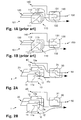
- the inverters are comprised in inverter modules, that may be easily replaced in the case of defects, or further modules may be easily added if the load is increased or if a higher redundancy level is desired.
- a detection circuit or several detection circuits are arranged outside the inverter modules, e. g. within the static switch, and all the modules are controlled by this circuit or these circuits, respectively.
- the detection circuits are connected to the output of the arrangement for connecting to the load, to the first input of the arrangement for connecting to the standard power source or directly to the power input of the load.
- the reliability of the system may be increased by additional redundancy if a plurality of DC power sources are provided that are connected to single inverter modules or groups of inverter modules.
- the modularity of the arrangement allows for easy adaptation to different needs relating to reliability, stability of the output current, required maximum load and power sources available.
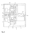
- the number of inverter modules 11, 12, 13 is chosen such that reliable power supply for the load output 50 is ensured even if one or more of the inverter modules fail, i. e. a certain redundancy is provided.
- this scheme ensures automatically that the switching devices 11a, 12a, 13a making sure that power is supplied without interruption in case of a failure of the mains, are as well provided redundantly. Therefore, failure of one of these switching devices 11a, 12a, 13a does not anymore lead to a general failure of the arrangement.
- the modular uninterrupted power supply system 2 further comprises a controller that has a variety of monitoring and controlling tasks, e. g. controlling the charging process, cooling equipment, regulating the function of the inverters, supervision of all internal processes, providing error messages etc.
- a controller that has a variety of monitoring and controlling tasks, e. g. controlling the charging process, cooling equipment, regulating the function of the inverters, supervision of all internal processes, providing error messages etc.
- this controller and related devices which as such are known from the prior art, are not displayed in Figure 3 .
- Some of the tasks of the controller may be performed by subordinate controllers integrated into the components of the power supply system 2 such as the inverter modules 11, 12, 13, the rectifier/charger module 5 or the switch module 30.
- the number of inverter modules may be freely varied depending on the required maximum power and the desired redundancy. Similarly, the number of backup power sources may be decreased to just one or increased to three or more; instead of batteries other power sources may be employed such as power capacitors etc. As mentioned above, the detection circuits for detecting failure of the standard power source may be arranged or distributed in a different way. The same is true for the arrangement of the switching devices within the inverter modules.
Landscapes
- Engineering & Computer Science (AREA)
- Power Engineering (AREA)
- Business, Economics & Management (AREA)
- Emergency Management (AREA)
- Inverter Devices (AREA)
- Stand-By Power Supply Arrangements (AREA)
Claims (9)
- Dispositif d'alimentation (1) ayant une première entrée (40) destinée à la connexion à une première source de courant, au moins une deuxième entrée (20) destinée à la connexion à au moins une deuxième source de courant et une sortie (50) destinée à la connexion à une charge, dans lequela) le dispositif (1) comprend au moins deux modules inverseurs parallèles (11, 12, 13) alimentés par ladite au moins une deuxième entrée (20) ; etb) chacun desdits modules inverseurs (11, 12, 13) comprend un commutateur interne (11a, 12a, 13a) pour commuter une connexion du module inverseur respectif (11, 12, 13) à ladite charge ;
caractérisé en ce quec) le dispositif comprend en outre un module commutateur statique (30) pour commuter une connexion de ladite première source de courant à ladite charge ; etd) le dispositif d'alimentation (1) peut être commuté d'un mode hors ligne, dans lequel le courant pour la sortie (50) destinée à la connexion à la charge est directement fourni de la première source de courant à travers un dispositif de commutation fermé (31) du module commutateur statique (30) et dans lequel les commutateurs internes (11a, 12a, 13a) des modules inverseurs (11, 12, 13) sont ouverts, dans un mode en ligne, en fermant les commutateurs internes (11a, 12a, 13a) des modules inverseurs (11, 12, 13) de sorte que les modules inverseurs (11, 12, 13) soient connectés à la sortie (50) destinée à la connexion à la charge et en ouvrant le dispositif de commutation (31) du module commutateur statique (30) pour séparer la sortie (50) destinée à la connexion à la charge de la première entrée (40), de telle manière que la fermeture des commutateurs internes (11a, 12a, 13a) se produise très rapidement afin que, dans le cas d'une panne de courant, la sortie (50) destinée à la connexion à la charge soit alimentée en permanence en courant. - Dispositif selon la revendication 1, caractérisé en ce qu'une sortie de chacun desdits modules inverseurs (11, 12, 13) est connectée en permanence à ladite sortie (50) destinée à la connexion à la charge.
- Dispositif selon la revendication 2, caractérisé en ce que les modules inverseurs (11, 12, 13) sont commandés de sorte que le commutateur interne (11a, 12a, 13a) de chacun desdits modules inverseurs (11, 12, 13) soit ouvert tant que la charge est alimentée par ladite première source de courant et que le commutateur interne (11a, 12a, 13a) soit fermé dès qu'une panne de courant est détectée à la charge.
- Dispositif selon la revendication 3, caractérisé en ce que chacun desdits modules inverseurs (11, 12, 13) comprend un circuit de détection (11c, 12c, 13c) connecté à une sortie du module inverseur (11, 12, 13) pour détecter la panne de courant à la charge.
- Dispositif selon l'une quelconque des revendications 1 à 4, caractérisé en ce que la première entrée (40) est apte à être connectée à une source de courant alternatif et en ce que l'au moins une deuxième entrée (20) est apte à être connectée à une source de courant continu (3, 4) telle qu'une batterie.
- Système modulaire d'alimentation sans coupure (2) comprenant le dispositif d'alimentation (1) selon la revendication 5, comprenant en outre une source de courant continu (3, 4) connectée à une entrée de la pluralité de modules inverseurs parallèles (11, 12, 13).
- Dispositif d'alimentation (1) selon l'une quelconque des revendications 1 à 5, comprenant un module inverseur (11, 12, 13) comportant une entrée destinée à la connexion à une source de courant continu et une sortie destinée à la connexion à une charge de courant alternatif, comprenant un circuit inverseur (11b, 12b, 13b) et un commutateur interne (11a, 12a, 13a) pour commuter une connexion de ladite entrée à ladite sortie, de telle manière que le commutateur interne (11a, 12a, 13a) puisse être fermé très rapidement afin que la sortie (50) destinée à la connexion à la charge soit alimentée en permanence en courant.
- Dispositif d'alimentation (1) du module inverseur selon la revendication 7, caractérisé en ce que le commutateur interne (11a, 12a, 13a) est connecté entre ledit circuit inverseur (11b, 12b, 13b) et ladite sortie.
- Dispositif d'alimentation (1) du module inverseur selon la revendication 7 ou 8, caractérisé par un circuit de détection (11c, 12c, 13c) connecté à ladite sortie pour détecter une panne de courant à la charge, de telle manière que le module inverseur (11, 12, 13) soit commandé afin que le commutateur interne (11a, 12a, 13a) soit fermé dès que la panne de courant est détectée.
Priority Applications (3)
| Application Number | Priority Date | Filing Date | Title |
|---|---|---|---|
| EP20050405288 EP1713155B1 (fr) | 2005-04-12 | 2005-04-12 | Dispositif d'alimentation |
| US11/396,628 US7450406B2 (en) | 2005-04-12 | 2006-04-04 | Power supply arrangement |
| CN2006100747814A CN1848600B (zh) | 2005-04-12 | 2006-04-11 | 供电装置 |
Applications Claiming Priority (1)
| Application Number | Priority Date | Filing Date | Title |
|---|---|---|---|
| EP20050405288 EP1713155B1 (fr) | 2005-04-12 | 2005-04-12 | Dispositif d'alimentation |
Publications (2)
| Publication Number | Publication Date |
|---|---|
| EP1713155A1 EP1713155A1 (fr) | 2006-10-18 |
| EP1713155B1 true EP1713155B1 (fr) | 2012-10-17 |
Family
ID=34942961
Family Applications (1)
| Application Number | Title | Priority Date | Filing Date |
|---|---|---|---|
| EP20050405288 Not-in-force EP1713155B1 (fr) | 2005-04-12 | 2005-04-12 | Dispositif d'alimentation |
Country Status (3)
| Country | Link |
|---|---|
| US (1) | US7450406B2 (fr) |
| EP (1) | EP1713155B1 (fr) |
| CN (1) | CN1848600B (fr) |
Cited By (1)
| Publication number | Priority date | Publication date | Assignee | Title |
|---|---|---|---|---|
| RU2658621C2 (ru) * | 2015-12-23 | 2018-06-22 | Федеральное государственное бюджетное образовательное учреждение высшего образования "Поволжский государственный университет телекоммуникаций и информатики" (ФГБОУ ВО ПГУТИ) | Способ управления резервированными модулями источника бесперебойного питания |
Families Citing this family (27)
| Publication number | Priority date | Publication date | Assignee | Title |
|---|---|---|---|---|
| US8068208B2 (en) | 2006-12-01 | 2011-11-29 | Taiwan Semiconductor Manufacturing Company, Ltd. | System and method for improving immersion scanner overlay performance |
| US7888816B2 (en) | 2007-06-06 | 2011-02-15 | Liebert Corporation | Method and apparatus for maintaining uninterruptible power supplies |
| US8294297B2 (en) * | 2007-08-03 | 2012-10-23 | Ragingwire Enterprise Solutions, Inc. | Scalable distributed redundancy |
| US8212401B2 (en) * | 2007-08-03 | 2012-07-03 | Stratascale, Inc. | Redundant isolation and bypass of critical power equipment |
| JP2009223938A (ja) * | 2008-03-14 | 2009-10-01 | Ricoh Co Ltd | 光ピックアップおよびこれを用いる光情報処理装置 |
| WO2010091244A2 (fr) * | 2009-02-05 | 2010-08-12 | Enphase Energy, Inc. | Procédé et appareil permettant de déterminer une tension de contrôle corrigée |
| CN101806847A (zh) * | 2009-02-18 | 2010-08-18 | 鸿富锦精密工业(深圳)有限公司 | 电子设备故障诊断系统、电子设备及故障诊断设备 |
| US8125747B2 (en) * | 2009-03-16 | 2012-02-28 | Honeywell International Inc. | Method for mitigating negative sequence effect resulting from non-symmetrical short circuit failure of synchronous electric machine based systems |
| EP2273664B1 (fr) * | 2009-07-07 | 2013-02-27 | Giga-Byte Technology Co., Ltd. | Dispositif de commande PWM et son procédé de commande |
| CN101989066B (zh) * | 2009-08-06 | 2013-07-31 | 技嘉科技股份有限公司 | 脉冲宽度调变控制装置以及其驱动方法 |
| IN2012DN02690A (fr) * | 2009-09-12 | 2015-09-04 | Fenix International Inc | |
| US8084892B2 (en) * | 2010-05-28 | 2011-12-27 | Mitsubishi Heavy Industries, Ltd. | Power supply device and method |
| EP2512000B1 (fr) | 2011-04-15 | 2022-03-02 | ABB Schweiz AG | Systèmes et convertisseurs de puissance reconfigurables |
| CN102629778B (zh) * | 2011-11-09 | 2014-03-26 | 广东志成冠军集团有限公司 | 多制式模块化eps应急电源 |
| DE102012101171A1 (de) * | 2012-02-14 | 2013-08-14 | Aeg Power Solutions B.V. | Anordnung und Verfahren zur unterbrechungsfreien Stromversorgung |
| US20130229858A1 (en) * | 2012-03-02 | 2013-09-05 | Maxwell Consulting | Fault Tolerant Static Random-Access Memory |
| US9793753B2 (en) * | 2012-09-21 | 2017-10-17 | Schneider Electric It Corporation | Power quality detector |
| FR2998364B1 (fr) | 2012-11-19 | 2015-01-02 | Continental Automotive France | Capteur inductif de vehicule automobile comportant des oscillateurs electriques adaptes a former par phenomene de resonance electrique une tension alternative aux bornes d'une bobine d'excitation |
| CN104044475B (zh) * | 2013-03-15 | 2017-07-11 | 通用电气公司 | 改进的驱动系统以及使用该驱动系统的装置 |
| US9479011B2 (en) | 2013-12-05 | 2016-10-25 | General Electric Company | Method and system for a dual conversion uninterruptible power supply |
| CN104901410A (zh) * | 2014-03-04 | 2015-09-09 | 伊顿公司 | 一种ups电路 |
| KR101668335B1 (ko) * | 2014-10-08 | 2016-10-24 | 창명제어기술 (주) | 단상 인버터 장치 |
| CN105186571B (zh) * | 2015-10-23 | 2018-08-24 | 苏州华安普电力科技股份有限公司 | 一种光伏并网逆变器的智能低电压穿越系统 |
| JP6191745B1 (ja) * | 2016-08-10 | 2017-09-06 | 富士電機株式会社 | 無停電電源装置 |
| CN106849325B (zh) | 2016-11-30 | 2019-10-18 | 西安华为技术有限公司 | 一种模块化ups及其工作方法 |
| US10103665B2 (en) * | 2017-01-06 | 2018-10-16 | General Electric Company | Protection for redundancy of isolated inverter blocks |
| FR3078454B1 (fr) * | 2018-02-27 | 2021-01-15 | Commissariat Energie Atomique | Module d’alimentation pour moteur de vehicule electrique |
Family Cites Families (19)
| Publication number | Priority date | Publication date | Assignee | Title |
|---|---|---|---|---|
| US4783728A (en) * | 1986-04-29 | 1988-11-08 | Modular Power Corp. | Modular power supply with PLL control |
| US5237208A (en) * | 1988-10-25 | 1993-08-17 | Nishimu Electronics Industries Co., Ltd. | Apparatus for parallel operation of triport uninterruptable power source devices |
| US5450309A (en) * | 1990-11-19 | 1995-09-12 | Inventio Ag | Method and device for switching inverters in parallel |
| GB2264403B (en) * | 1992-02-18 | 1996-09-04 | Hitachi Ltd | An apparatus for controlling parallel running of inverters |
| US5814904A (en) * | 1995-03-28 | 1998-09-29 | Cyberex, Inc. | Static switch method and apparatus |
| US5745356A (en) * | 1996-06-25 | 1998-04-28 | Exide Electronics Corporation | Independent load sharing of AC power systems connected in parallel |
| US5757634A (en) * | 1996-12-24 | 1998-05-26 | Siemans Electric Limited | Multiparalleling system of voltage source power converters |
| US5920129A (en) * | 1998-01-07 | 1999-07-06 | Lucent Technologies Inc. | Uninterruptible power supply having solid state transfer switch and method of operation thereof |
| US6072707A (en) * | 1998-10-23 | 2000-06-06 | Siemens Power Transmission & Distribution, Inc. | High voltage modular inverter |
| US6134124A (en) * | 1999-05-12 | 2000-10-17 | Abb Power T&D Company Inc. | Universal distributed-resource interface |
| DE10060429A1 (de) * | 1999-12-16 | 2001-07-12 | Caterpillar Inc | Verfahren und Vorrichtung zur Leistungsübertragung |
| FR2812474B1 (fr) * | 2000-07-31 | 2004-06-18 | Valeo Climatisation | Dispositif de protection d'une source electrique propre a alimenter un organe electrique |
| US6605879B2 (en) * | 2001-04-19 | 2003-08-12 | Powerware Corporation | Battery charger control circuit and an uninterruptible power supply utilizing same |
| US20030227785A1 (en) * | 2002-06-06 | 2003-12-11 | Johnson Robert W. | On-line uninterruptible power supplies with two-relay bypass circuit and methods of operation thereof |
| US6977446B2 (en) * | 2002-08-22 | 2005-12-20 | Robin Mackay | Multiple inverter power system with regard to generator failure |
| US7129599B2 (en) * | 2002-10-15 | 2006-10-31 | Soft Switching Technologies Corporation | Dual feed power supply systems with enhanced power quality |
| JP2006509489A (ja) * | 2002-12-06 | 2006-03-16 | エレクトリック パワー リサーチ インスチテュート インコーポレイテッド | 無停電源及び発電システム |
| CN2624497Y (zh) * | 2003-05-16 | 2004-07-07 | 青岛经济技术开发区创统科技发展有限公司 | 动力设备和生产线用多功能eps电源 |
| US20050036253A1 (en) * | 2003-08-13 | 2005-02-17 | Shou-Long Tian | Modular AC power supply system with fault bypass and method of switching output modes |
-
2005
- 2005-04-12 EP EP20050405288 patent/EP1713155B1/fr not_active Not-in-force
-
2006
- 2006-04-04 US US11/396,628 patent/US7450406B2/en active Active
- 2006-04-11 CN CN2006100747814A patent/CN1848600B/zh not_active Expired - Fee Related
Cited By (1)
| Publication number | Priority date | Publication date | Assignee | Title |
|---|---|---|---|---|
| RU2658621C2 (ru) * | 2015-12-23 | 2018-06-22 | Федеральное государственное бюджетное образовательное учреждение высшего образования "Поволжский государственный университет телекоммуникаций и информатики" (ФГБОУ ВО ПГУТИ) | Способ управления резервированными модулями источника бесперебойного питания |
Also Published As
| Publication number | Publication date |
|---|---|
| US7450406B2 (en) | 2008-11-11 |
| EP1713155A1 (fr) | 2006-10-18 |
| CN1848600B (zh) | 2012-08-08 |
| US20060227579A1 (en) | 2006-10-12 |
| CN1848600A (zh) | 2006-10-18 |
Similar Documents
| Publication | Publication Date | Title |
|---|---|---|
| EP1713155B1 (fr) | Dispositif d'alimentation | |
| US10978904B2 (en) | Reserve power system transfer switches for data center | |
| EP3235104B1 (fr) | Systèmes électriques et procédés utilisant la signalisation de forme d'onde de tension | |
| US7129599B2 (en) | Dual feed power supply systems with enhanced power quality | |
| US11742669B2 (en) | Wind turbine with integrated battery storage | |
| US6288456B1 (en) | Power system | |
| US10284008B2 (en) | Isolated parallel ups system with fault location detection | |
| WO2018221040A1 (fr) | Système de stockage d'énergie | |
| US10014713B1 (en) | Redundant secondary power support system | |
| US20170354067A1 (en) | Power system and method | |
| US20070152506A1 (en) | Telecommunications megasite with backup power system | |
| KR101021598B1 (ko) | 순간정전 보상장치 | |
| JPWO2020021925A1 (ja) | 電源システム | |
| JP5146514B2 (ja) | 切替装置、切替装置制御方法、切替装置制御プログラム | |
| JP2011097676A (ja) | 無停電電源システム | |
| JPH0583860A (ja) | 電力変換装置 | |
| RU2215355C1 (ru) | Установка бесперебойного электроснабжения железнодорожной автоматики | |
| US10243511B1 (en) | Automatic modularity control for multi power stack air cooled inverter | |
| GB2626732A (en) | Uninterruptible power supply with an autonomous under frequency detection and load shedding functionality | |
| JP2024073768A (ja) | 無停電電源装置 |
Legal Events
| Date | Code | Title | Description |
|---|---|---|---|
| PUAI | Public reference made under article 153(3) epc to a published international application that has entered the european phase |
Free format text: ORIGINAL CODE: 0009012 |
|
| AK | Designated contracting states |
Kind code of ref document: A1 Designated state(s): AT BE BG CH CY CZ DE DK EE ES FI FR GB GR HU IE IS IT LI LT LU MC NL PL PT RO SE SI SK TR |
|
| AX | Request for extension of the european patent |
Extension state: AL BA HR LV MK YU |
|
| 17P | Request for examination filed |
Effective date: 20070116 |
|
| AKX | Designation fees paid |
Designated state(s): AT BE BG CH CY CZ DE DK EE ES FI FR GB GR HU IE IS IT LI LT LU MC NL PL PT RO SE SI SK TR |
|
| 17Q | First examination report despatched |
Effective date: 20090514 |
|
| REG | Reference to a national code |
Ref country code: DE Ref legal event code: R079 Ref document number: 602005036559 Country of ref document: DE Free format text: PREVIOUS MAIN CLASS: H02J0009000000 Ipc: H02J0009060000 |
|
| GRAP | Despatch of communication of intention to grant a patent |
Free format text: ORIGINAL CODE: EPIDOSNIGR1 |
|
| RIC1 | Information provided on ipc code assigned before grant |
Ipc: H02J 9/00 20060101ALI20120417BHEP Ipc: H02M 7/493 20070101ALI20120417BHEP Ipc: H02J 9/06 20060101AFI20120417BHEP |
|
| GRAS | Grant fee paid |
Free format text: ORIGINAL CODE: EPIDOSNIGR3 |
|
| GRAA | (expected) grant |
Free format text: ORIGINAL CODE: 0009210 |
|
| AK | Designated contracting states |
Kind code of ref document: B1 Designated state(s): AT BE BG CH CY CZ DE DK EE ES FI FR GB GR HU IE IS IT LI LT LU MC NL PL PT RO SE SI SK TR |
|
| REG | Reference to a national code |
Ref country code: GB Ref legal event code: FG4D |
|
| REG | Reference to a national code |
Ref country code: CH Ref legal event code: NV Representative=s name: KELLER & PARTNER PATENTANWAELTE AG Ref country code: CH Ref legal event code: EP |
|
| REG | Reference to a national code |
Ref country code: IE Ref legal event code: FG4D |
|
| REG | Reference to a national code |
Ref country code: AT Ref legal event code: REF Ref document number: 580267 Country of ref document: AT Kind code of ref document: T Effective date: 20121115 |
|
| REG | Reference to a national code |
Ref country code: SE Ref legal event code: TRGR |
|
| REG | Reference to a national code |
Ref country code: DE Ref legal event code: R096 Ref document number: 602005036559 Country of ref document: DE Effective date: 20121213 |
|
| REG | Reference to a national code |
Ref country code: AT Ref legal event code: MK05 Ref document number: 580267 Country of ref document: AT Kind code of ref document: T Effective date: 20121017 |
|
| REG | Reference to a national code |
Ref country code: NL Ref legal event code: VDEP Effective date: 20121017 |
|
| REG | Reference to a national code |
Ref country code: LT Ref legal event code: MG4D |
|
| PG25 | Lapsed in a contracting state [announced via postgrant information from national office to epo] |
Ref country code: NL Free format text: LAPSE BECAUSE OF FAILURE TO SUBMIT A TRANSLATION OF THE DESCRIPTION OR TO PAY THE FEE WITHIN THE PRESCRIBED TIME-LIMIT Effective date: 20121017 Ref country code: LT Free format text: LAPSE BECAUSE OF FAILURE TO SUBMIT A TRANSLATION OF THE DESCRIPTION OR TO PAY THE FEE WITHIN THE PRESCRIBED TIME-LIMIT Effective date: 20121017 Ref country code: IS Free format text: LAPSE BECAUSE OF FAILURE TO SUBMIT A TRANSLATION OF THE DESCRIPTION OR TO PAY THE FEE WITHIN THE PRESCRIBED TIME-LIMIT Effective date: 20130217 Ref country code: FI Free format text: LAPSE BECAUSE OF FAILURE TO SUBMIT A TRANSLATION OF THE DESCRIPTION OR TO PAY THE FEE WITHIN THE PRESCRIBED TIME-LIMIT Effective date: 20121017 Ref country code: ES Free format text: LAPSE BECAUSE OF FAILURE TO SUBMIT A TRANSLATION OF THE DESCRIPTION OR TO PAY THE FEE WITHIN THE PRESCRIBED TIME-LIMIT Effective date: 20130128 |
|
| PG25 | Lapsed in a contracting state [announced via postgrant information from national office to epo] |
Ref country code: CY Free format text: LAPSE BECAUSE OF FAILURE TO SUBMIT A TRANSLATION OF THE DESCRIPTION OR TO PAY THE FEE WITHIN THE PRESCRIBED TIME-LIMIT Effective date: 20121017 Ref country code: GR Free format text: LAPSE BECAUSE OF FAILURE TO SUBMIT A TRANSLATION OF THE DESCRIPTION OR TO PAY THE FEE WITHIN THE PRESCRIBED TIME-LIMIT Effective date: 20130118 Ref country code: PL Free format text: LAPSE BECAUSE OF FAILURE TO SUBMIT A TRANSLATION OF THE DESCRIPTION OR TO PAY THE FEE WITHIN THE PRESCRIBED TIME-LIMIT Effective date: 20121017 Ref country code: PT Free format text: LAPSE BECAUSE OF FAILURE TO SUBMIT A TRANSLATION OF THE DESCRIPTION OR TO PAY THE FEE WITHIN THE PRESCRIBED TIME-LIMIT Effective date: 20130218 Ref country code: SI Free format text: LAPSE BECAUSE OF FAILURE TO SUBMIT A TRANSLATION OF THE DESCRIPTION OR TO PAY THE FEE WITHIN THE PRESCRIBED TIME-LIMIT Effective date: 20121017 Ref country code: BE Free format text: LAPSE BECAUSE OF FAILURE TO SUBMIT A TRANSLATION OF THE DESCRIPTION OR TO PAY THE FEE WITHIN THE PRESCRIBED TIME-LIMIT Effective date: 20121017 |
|
| PG25 | Lapsed in a contracting state [announced via postgrant information from national office to epo] |
Ref country code: AT Free format text: LAPSE BECAUSE OF FAILURE TO SUBMIT A TRANSLATION OF THE DESCRIPTION OR TO PAY THE FEE WITHIN THE PRESCRIBED TIME-LIMIT Effective date: 20121017 |
|
| PG25 | Lapsed in a contracting state [announced via postgrant information from national office to epo] |
Ref country code: BG Free format text: LAPSE BECAUSE OF FAILURE TO SUBMIT A TRANSLATION OF THE DESCRIPTION OR TO PAY THE FEE WITHIN THE PRESCRIBED TIME-LIMIT Effective date: 20130117 Ref country code: EE Free format text: LAPSE BECAUSE OF FAILURE TO SUBMIT A TRANSLATION OF THE DESCRIPTION OR TO PAY THE FEE WITHIN THE PRESCRIBED TIME-LIMIT Effective date: 20121017 Ref country code: DK Free format text: LAPSE BECAUSE OF FAILURE TO SUBMIT A TRANSLATION OF THE DESCRIPTION OR TO PAY THE FEE WITHIN THE PRESCRIBED TIME-LIMIT Effective date: 20121017 Ref country code: SK Free format text: LAPSE BECAUSE OF FAILURE TO SUBMIT A TRANSLATION OF THE DESCRIPTION OR TO PAY THE FEE WITHIN THE PRESCRIBED TIME-LIMIT Effective date: 20121017 Ref country code: CZ Free format text: LAPSE BECAUSE OF FAILURE TO SUBMIT A TRANSLATION OF THE DESCRIPTION OR TO PAY THE FEE WITHIN THE PRESCRIBED TIME-LIMIT Effective date: 20121017 |
|
| PLBE | No opposition filed within time limit |
Free format text: ORIGINAL CODE: 0009261 |
|
| STAA | Information on the status of an ep patent application or granted ep patent |
Free format text: STATUS: NO OPPOSITION FILED WITHIN TIME LIMIT |
|
| PG25 | Lapsed in a contracting state [announced via postgrant information from national office to epo] |
Ref country code: RO Free format text: LAPSE BECAUSE OF FAILURE TO SUBMIT A TRANSLATION OF THE DESCRIPTION OR TO PAY THE FEE WITHIN THE PRESCRIBED TIME-LIMIT Effective date: 20121017 |
|
| 26N | No opposition filed |
Effective date: 20130718 |
|
| REG | Reference to a national code |
Ref country code: DE Ref legal event code: R097 Ref document number: 602005036559 Country of ref document: DE Effective date: 20130718 |
|
| PG25 | Lapsed in a contracting state [announced via postgrant information from national office to epo] |
Ref country code: MC Free format text: LAPSE BECAUSE OF FAILURE TO SUBMIT A TRANSLATION OF THE DESCRIPTION OR TO PAY THE FEE WITHIN THE PRESCRIBED TIME-LIMIT Effective date: 20121017 |
|
| REG | Reference to a national code |
Ref country code: IE Ref legal event code: MM4A |
|
| PG25 | Lapsed in a contracting state [announced via postgrant information from national office to epo] |
Ref country code: IE Free format text: LAPSE BECAUSE OF NON-PAYMENT OF DUE FEES Effective date: 20130412 |
|
| REG | Reference to a national code |
Ref country code: CH Ref legal event code: PCAR Free format text: NEW ADDRESS: EIGERSTRASSE 2 POSTFACH, 3000 BERN 14 (CH) |
|
| REG | Reference to a national code |
Ref country code: FR Ref legal event code: PLFP Year of fee payment: 11 |
|
| PG25 | Lapsed in a contracting state [announced via postgrant information from national office to epo] |
Ref country code: TR Free format text: LAPSE BECAUSE OF FAILURE TO SUBMIT A TRANSLATION OF THE DESCRIPTION OR TO PAY THE FEE WITHIN THE PRESCRIBED TIME-LIMIT Effective date: 20121017 |
|
| PG25 | Lapsed in a contracting state [announced via postgrant information from national office to epo] |
Ref country code: HU Free format text: LAPSE BECAUSE OF FAILURE TO SUBMIT A TRANSLATION OF THE DESCRIPTION OR TO PAY THE FEE WITHIN THE PRESCRIBED TIME-LIMIT; INVALID AB INITIO Effective date: 20050412 Ref country code: LU Free format text: LAPSE BECAUSE OF NON-PAYMENT OF DUE FEES Effective date: 20130412 |
|
| REG | Reference to a national code |
Ref country code: FR Ref legal event code: PLFP Year of fee payment: 12 |
|
| REG | Reference to a national code |
Ref country code: FR Ref legal event code: PLFP Year of fee payment: 13 |
|
| REG | Reference to a national code |
Ref country code: FR Ref legal event code: PLFP Year of fee payment: 14 |
|
| REG | Reference to a national code |
Ref country code: CH Ref legal event code: PUE Owner name: DELTA ELECTRONICS (THAILAND) PUBLIC CO., LTD., TH Free format text: FORMER OWNER: DET INTERNATIONAL HOLDING LIMITED, KY |
|
| REG | Reference to a national code |
Ref country code: DE Ref legal event code: R082 Ref document number: 602005036559 Country of ref document: DE Representative=s name: LENZING GERBER STUTE PARTNERSCHAFTSGESELLSCHAF, DE Ref country code: DE Ref legal event code: R081 Ref document number: 602005036559 Country of ref document: DE Owner name: DELTA ELECTRONICS (THAILAND) PUBLIC CO., LTD.,, TH Free format text: FORMER OWNER: DET INTERNATIONAL HOLDING LTD., GEORGE TOWN, GRAND CAYMAN, KY |
|
| REG | Reference to a national code |
Ref country code: CH Ref legal event code: PFA Owner name: DELTA ELECTRONICS (THAILAND) PUBLIC CO., LTD., TH Free format text: FORMER OWNER: DELTA ELECTRONICS (THAILAND) PUBLIC CO., LTD., TH |
|
| REG | Reference to a national code |
Ref country code: GB Ref legal event code: 732E Free format text: REGISTERED BETWEEN 20200917 AND 20200923 |
|
| PGFP | Annual fee paid to national office [announced via postgrant information from national office to epo] |
Ref country code: DE Payment date: 20210420 Year of fee payment: 17 Ref country code: FR Payment date: 20210423 Year of fee payment: 17 Ref country code: IT Payment date: 20210422 Year of fee payment: 17 |
|
| PGFP | Annual fee paid to national office [announced via postgrant information from national office to epo] |
Ref country code: GB Payment date: 20210421 Year of fee payment: 17 Ref country code: CH Payment date: 20210420 Year of fee payment: 17 Ref country code: SE Payment date: 20210420 Year of fee payment: 17 |
|
| REG | Reference to a national code |
Ref country code: DE Ref legal event code: R119 Ref document number: 602005036559 Country of ref document: DE |
|
| REG | Reference to a national code |
Ref country code: SE Ref legal event code: EUG |
|
| REG | Reference to a national code |
Ref country code: CH Ref legal event code: PL |
|
| GBPC | Gb: european patent ceased through non-payment of renewal fee |
Effective date: 20220412 |
|
| PG25 | Lapsed in a contracting state [announced via postgrant information from national office to epo] |
Ref country code: SE Free format text: LAPSE BECAUSE OF NON-PAYMENT OF DUE FEES Effective date: 20220413 Ref country code: LI Free format text: LAPSE BECAUSE OF NON-PAYMENT OF DUE FEES Effective date: 20220430 Ref country code: GB Free format text: LAPSE BECAUSE OF NON-PAYMENT OF DUE FEES Effective date: 20220412 Ref country code: FR Free format text: LAPSE BECAUSE OF NON-PAYMENT OF DUE FEES Effective date: 20220430 Ref country code: DE Free format text: LAPSE BECAUSE OF NON-PAYMENT OF DUE FEES Effective date: 20221103 Ref country code: CH Free format text: LAPSE BECAUSE OF NON-PAYMENT OF DUE FEES Effective date: 20220430 |
|
| PG25 | Lapsed in a contracting state [announced via postgrant information from national office to epo] |
Ref country code: IT Free format text: LAPSE BECAUSE OF NON-PAYMENT OF DUE FEES Effective date: 20220412 |