EP1712894B1 - Particle counter for foreign particles in a liquid flow - Google Patents
Particle counter for foreign particles in a liquid flow Download PDFInfo
- Publication number
- EP1712894B1 EP1712894B1 EP06111901A EP06111901A EP1712894B1 EP 1712894 B1 EP1712894 B1 EP 1712894B1 EP 06111901 A EP06111901 A EP 06111901A EP 06111901 A EP06111901 A EP 06111901A EP 1712894 B1 EP1712894 B1 EP 1712894B1
- Authority
- EP
- European Patent Office
- Prior art keywords
- particle counter
- piston
- cylinder
- measuring
- pressure
- Prior art date
- Legal status (The legal status is an assumption and is not a legal conclusion. Google has not performed a legal analysis and makes no representation as to the accuracy of the status listed.)
- Expired - Fee Related
Links
Images
Classifications
-
- G—PHYSICS
- G01—MEASURING; TESTING
- G01N—INVESTIGATING OR ANALYSING MATERIALS BY DETERMINING THEIR CHEMICAL OR PHYSICAL PROPERTIES
- G01N15/00—Investigating characteristics of particles; Investigating permeability, pore-volume, or surface-area of porous materials
- G01N15/10—Investigating individual particles
- G01N15/14—Electro-optical investigation, e.g. flow cytometers
-
- G—PHYSICS
- G05—CONTROLLING; REGULATING
- G05D—SYSTEMS FOR CONTROLLING OR REGULATING NON-ELECTRIC VARIABLES
- G05D16/00—Control of fluid pressure
- G05D16/04—Control of fluid pressure without auxiliary power
- G05D16/10—Control of fluid pressure without auxiliary power the sensing element being a piston or plunger
-
- G—PHYSICS
- G01—MEASURING; TESTING
- G01N—INVESTIGATING OR ANALYSING MATERIALS BY DETERMINING THEIR CHEMICAL OR PHYSICAL PROPERTIES
- G01N15/00—Investigating characteristics of particles; Investigating permeability, pore-volume, or surface-area of porous materials
- G01N15/10—Investigating individual particles
- G01N15/14—Electro-optical investigation, e.g. flow cytometers
- G01N15/1434—Electro-optical investigation, e.g. flow cytometers using an analyser being characterised by its optical arrangement
-
- G—PHYSICS
- G01—MEASURING; TESTING
- G01N—INVESTIGATING OR ANALYSING MATERIALS BY DETERMINING THEIR CHEMICAL OR PHYSICAL PROPERTIES
- G01N1/00—Sampling; Preparing specimens for investigation
- G01N1/02—Devices for withdrawing samples
- G01N1/10—Devices for withdrawing samples in the liquid or fluent state
- G01N1/20—Devices for withdrawing samples in the liquid or fluent state for flowing or falling materials
- G01N1/2035—Devices for withdrawing samples in the liquid or fluent state for flowing or falling materials by deviating part of a fluid stream, e.g. by drawing-off or tapping
- G01N2001/2064—Devices for withdrawing samples in the liquid or fluent state for flowing or falling materials by deviating part of a fluid stream, e.g. by drawing-off or tapping using a by-pass loop
-
- G—PHYSICS
- G01—MEASURING; TESTING
- G01N—INVESTIGATING OR ANALYSING MATERIALS BY DETERMINING THEIR CHEMICAL OR PHYSICAL PROPERTIES
- G01N15/00—Investigating characteristics of particles; Investigating permeability, pore-volume, or surface-area of porous materials
- G01N15/10—Investigating individual particles
- G01N15/14—Electro-optical investigation, e.g. flow cytometers
- G01N2015/1486—Counting the particles
-
- G—PHYSICS
- G01—MEASURING; TESTING
- G01N—INVESTIGATING OR ANALYSING MATERIALS BY DETERMINING THEIR CHEMICAL OR PHYSICAL PROPERTIES
- G01N15/00—Investigating characteristics of particles; Investigating permeability, pore-volume, or surface-area of porous materials
- G01N15/10—Investigating individual particles
- G01N15/14—Electro-optical investigation, e.g. flow cytometers
- G01N2015/1493—Particle size
-
- G—PHYSICS
- G01—MEASURING; TESTING
- G01N—INVESTIGATING OR ANALYSING MATERIALS BY DETERMINING THEIR CHEMICAL OR PHYSICAL PROPERTIES
- G01N21/00—Investigating or analysing materials by the use of optical means, i.e. using sub-millimetre waves, infrared, visible or ultraviolet light
- G01N21/84—Systems specially adapted for particular applications
- G01N21/85—Investigating moving fluids or granular solids
- G01N2021/8557—Special shaping of flow, e.g. using a by-pass line, jet flow, curtain flow
-
- G—PHYSICS
- G01—MEASURING; TESTING
- G01N—INVESTIGATING OR ANALYSING MATERIALS BY DETERMINING THEIR CHEMICAL OR PHYSICAL PROPERTIES
- G01N21/00—Investigating or analysing materials by the use of optical means, i.e. using sub-millimetre waves, infrared, visible or ultraviolet light
- G01N21/17—Systems in which incident light is modified in accordance with the properties of the material investigated
- G01N21/47—Scattering, i.e. diffuse reflection
- G01N21/49—Scattering, i.e. diffuse reflection within a body or fluid
- G01N21/53—Scattering, i.e. diffuse reflection within a body or fluid within a flowing fluid, e.g. smoke
- G01N21/534—Scattering, i.e. diffuse reflection within a body or fluid within a flowing fluid, e.g. smoke by measuring transmission alone, i.e. determining opacity
Definitions
- the invention relates to a particle counter operating according to the dimming or light blockade method for counting foreign particles in a liquid flow, in particular in a hydraulic fluid flow, according to the preamble of patent claim 1.
- Such a particle counter is off DE 89 12 584 U1 known.
- a complex volume flow control device is required to achieve a constant flow velocity within the measuring channel.
- a generic measuring device is still known from DE 20 62 698 A1 and described in the non-prepublished WO 2005/038434 A1 , With the particle counters of these devices, only constant volume flows can be checked with respect to their particle content with a volume flow to be observed defined, wherein the constant flow rate must be achieved by constant-flow medium.
- the invention is concerned with the problem of creating a particle counter which is as simple as possible and yet operates with high measuring accuracy.
- a particle counter should be part of a working device through which liquid to be measured flows.
- the liquid should in particular be hydraulic oil of a hydraulically operating device, the degree of contamination of which is determined stationarily with such a particle counter can be and in any short time intervals. It should also be possible to be able to recognize different particle sizes separately. In particular, a continuous monitoring of the degree of contamination of such a hydraulic fluid with a particle counter according to the invention should be possible.
- the volume flow per measuring time must be known.
- the size of a volume flow is known, for example, if it can be set to a specific value and kept constant.
- a constant volume flow in turn, necessarily results in a geometrically constant flow channel at a constant predetermined pressure gradient along this flow channel.
- an additional prerequisite is that the flowing liquid has a constant viscosity value. Since the viscosity value of a liquid is usually temperature-dependent, in particular for a hydraulic fluid, it sets at a constant pressure Pressure gradient a constant volume flow Temperature equality ahead.
- a heating or cooling device for influencing the temperature of the liquid stream to be measured.
- the cooling or heating device is designed so that there is a temperature for performing a measurement, which is preferably outside a possible operating temperature. This ensures that, regardless of current operating temperatures, a measurement can always be carried out at the same measuring temperature outside an operating temperature.
- a heating device is used by which a measuring, that is to say an active operation of a particle counter, always lies at a temperature above the operating temperature of the liquid to be measured with regard to its particle loading.
- the device according to the invention can also be advantageously used in particular for measuring and monitoring the degree of soiling of transmission oil.
- the influence of a changing viscosity on a constant liquid flow to be generated by a pressure difference in a measuring channel is eliminated by a specific temperature control of the measuring liquid flow.
- Another possibility (which is not part of the invention) of avoiding a changing viscosity as a disturbance factor for the measurement consists of detecting the temperature of the measuring liquid in the measuring channel and the respective measured values of the particle counting by an electronically stored, in particular experimentally dependent to correct the correction curve determined for different measuring fluid temperatures. Correcting here means that viscosity-related changes in the volume flow of the measuring liquid flow are neutralized according to an electronic correction memory, wherein the correction memory is to be created with reference in each case to a liquid to be measured.
- different correction values can be stored for different liquids and retrieved as needed.
- the particle counter is formed in a, in a liquid, in particular hydraulic fluid line, usable measuring device.
- Incoming liquid flows in a main flow into a main flow channel opening 1 of a main flow channel 2 and leaves this main flow channel 2 through a main flow channel outlet opening 3.
- a spring-loaded throttle valve 4 is integrated in the main flow channel 2.
- This throttle valve 4 comprises a, in a cylinder 5 slidably mounted piston 6.
- the cylinder 5 is provided at one end with a closed bottom 7 in the form of a sealing plug and the other end open. From this open end of the cylinder 5, the piston 6 can penetrate into the flow path of the main flow channel 2 and completely close this path.
- the piston 6 bears against a valve seat 8 arranged correspondingly in the main flow channel 2. In the direction of a closed position on the valve seat 8, the piston 6 is acted upon by a force applied in the interior of the cylinder 5 spring 9.
- the spring 9 is supported at one end on the piston 6 and the other end on the bottom 7 of the cylinder.
- the axis of the cylinder 5, along which the piston 6 can move, is inclined relative to the longitudinal axis of the main flow channel 2, that liquid flowing from the inlet opening 1 into the main flow channel 2 can act on the end face of the piston 6 in a throttle valve opening manner.
- This opening force counteracts the force of the spring 9, which is designed here as a compression spring.
- the flow direction of the main flow channel 2 is marked with flow arrows S.
- the main flow channel 2 Downstream of the piston 6 of the throttle valve 4, the main flow channel 2 is pressure-equalizing connected via a connecting channel 10 in, for example, the shape of a throttle channel with the interior of the cylinder 5.
- the light barrier measurement according to the invention by the dimming or light blockade method which is known per se in the prior art is carried out in a measuring channel 11, which is designed as a bypass bridging the throttle valve 4 to the main flow channel 2.
- a measuring channel 11 which is designed as a bypass bridging the throttle valve 4 to the main flow channel 2.
- the connection openings of this measuring channel are shown, wherein the measuring channel inlet located upstream of the throttle valve 4 is denoted by 12 and the measuring channel outlet by 13.
- the measuring channel 11 is associated with a known per se in such a particle counter sensor device 14.
- this measuring channel 11 penetrates a heating device 15 in its supply region.
- the liquid flowing through is heated to a predetermined temperature value outside the possible operating temperatures, whereby this liquid causes the sensor device 14 always flows through an equal, constant temperature.
- the electronic part of the particle counter is in the Fig. 1 indicated by 16.
- This electronic part 16 comprises the devices for, for example, a telemetric remote display of the measured values from the sensor device 14, including their measured values, which are evaluated in particular in this electronic part.
- the display of the evaluated measured values can be done digitally or analogously at any desired location in a manner known per se.
- a telemetric remote display is particularly interesting when using a particle counter according to the invention for monitoring a hydraulic oil circuit in an offshore wind turbine, for example.
- the throttle valve 4 may be designed for example by a corresponding spring 9 for a constant pressure drop of 0.5 bar within the main flow channel 2.
- the measuring channel volume flow defined hereby and by the size of the flow cross-section of the measuring channel 11 can be, for example, 50 ml / min.
- a single-channel laser device can be used as a sensor device 14.
- the achievable measured values and their evaluation possibilities correspond to the well-known in generic particle counters state of the art, which is why this need not be discussed in detail in the description of the present invention.
- a calibration of the measuring device with a test liquid adapted to the liquid to be measured is required in each case.
- Each test fluid is mixed with a precisely defined test dust.
- the measuring device With the measuring device according to the invention, it is possible to determine the particle size in a measuring window, so that the evaluation of the measurement result can be switched to preset classes of particle sizes by simply switching the measuring device.
- the switching can be done automatically by the electronics, so that a principle one-channel measuring device can work by repeatedly switching to another class such as a multi-channel measuring device. This is a special feature of the present invention.
- a measurement accuracy of at least about +/- 20% can be ensured without further ado.
Description
Die Erfindung betrifft einen nach dem Abdunkelungs- bzw. Lichtblockadeverfahren arbeitenden Partikelzähler zum Zählen von Fremdpartikeln in einem Flüssigkeitsstrom, insbesondere in einem Hydraulikflüssigkeitsstrom, nach dem Oberbegriff des Patentanspruchs 1.The invention relates to a particle counter operating according to the dimming or light blockade method for counting foreign particles in a liquid flow, in particular in a hydraulic fluid flow, according to the preamble of patent claim 1.
Ein solcher Partikelzähler ist aus
Eine gattungsgemäße Messeinrichtung ist weiterhin bekannt aus
Die Erfindung beschäftigt sich mit dem Problem, einen möglichst einfach aufgebauten und dennoch mit hoher Messgenauigkeit arbeitenden Partikelzähler zu schaffen. Ein solcher Partikelzähler soll Bestandteil einer von zu messender Flüssigkeit durchströmten Arbeitseinrichtung sein. Bei der Flüssigkeit soll es sich insbesondere um Hydrauliköl einer hydraulisch arbeitenden Einrichtung handeln, dessen Verschmutzungsgrad mit einem solchen Partikelzähler stationär ermittelt werden kann und zwar in beliebig kurzen Zeitabständen. Auch soll es möglich sein, unterschiedliche Partikelgrößen getrennt erkennen zu können. Insbesondere soll eine kontinuierliche Überwachung des Verschmutzungsgrades einer solchen Hydraulikflüssigkeit mit einem erfindungsgemäßen Partikelzähler möglich sein.The invention is concerned with the problem of creating a particle counter which is as simple as possible and yet operates with high measuring accuracy. Such a particle counter should be part of a working device through which liquid to be measured flows. The liquid should in particular be hydraulic oil of a hydraulically operating device, the degree of contamination of which is determined stationarily with such a particle counter can be and in any short time intervals. It should also be possible to be able to recognize different particle sizes separately. In particular, a continuous monitoring of the degree of contamination of such a hydraulic fluid with a particle counter according to the invention should be possible.
Die durch die kennzeichnenden Merkmale des Anspruchs 1 definierte Erfindung beruht dabei auf folgendem allgemeinen Gedanken.The defined by the characterizing features of claim 1 invention is based on the following general idea.
Um eine Messung der Anzahl und Größe von in einem Messstrom durch einen Messkanal strömender Flüssigkeit innerhalb einer Lichtschranke mit einem Abdunkelungs- bzw. Lichtblockadeverfahren ermitteln zu können, muss der Volumenstrom je Messzeit bekannt sein. Auf einfache Weise bekannt ist die Größe eines Volumenstromes beispielsweise, wenn dieser auf einen bestimmten Wert eingestellt und konstant gehalten werden kann. Ein konstanter Volumenstrom ergibt sich wiederum zwangsweise in einem geometrisch konstant gehaltenen Strömungskanal bei einem konstant vorgegebenen Druckgefälle längs dieses Strömungskanals. Zusätzliche Voraussetzung ist allerdings, dass die strömende Flüssigkeit einen konstanten Viskositätswert besitzt. Da der Viskositätswert einer Flüssigkeit in der Regel und zwar insbesondere bei einer Hydraulikflüssigkeit temperaturabhängig ist, setzt bei einem konstanten Druckgefälle ein konstanter Volumenstrom Temperaturgleichheit voraus. Diese beiden vorgenannten Voraussetzungen für einen konstanten Volumenstrom werden erfindungsgemäß bezüglich eines konstanten Druckabfalls durch ein federbelastet arbeitendes Druckreduzierventil und bezüglich einer gleichbleibenden Temperatur durch den Einsatz einer Heiz- oder Kühleinrichtung zur Beeinflussung der Temperatur des zu messenden Flüssigkeitsstromes erreicht. Die Kühl- oder Heizeinrichtung wird dabei so ausgelegt, dass zur Durchführung einer Messung eine Temperatur vorliegt, die vorzugsweise außerhalb einer möglichen Betriebstemperatur liegt. Dadurch ist gewährleistet, dass unabhängig von augenblicklichen Betriebstemperaturen stets eine Messung bei einer gleichen, außerhalb einer Betriebstemperatur liegenden Messtemperatur erfolgen kann. In der Regel wird eine Heizeinrichtung eingesetzt, durch die ein Messen, das heißt ein aktiver Betrieb eines Partikelzählers stets bei einer oberhalb der Betriebstemperatur der bezüglich ihrer Partikelbeladung zu messenden Flüssigkeit liegt. Durch diese erfindungsgemäße Lösung kann ein kompliziert aufgebauter und häufig wenig messgenau arbeitender Volumenstromregler, wie er beispielsweise bei dem vorbekannten Stand der Technik nach der eingangs zitierten
Vorteilhafte und zweckmäßige Ausgestaltungen der Erfindung sind Gegenstand der Unteransprüche und werden anhand eines Ausführungsbeispieles nachstehend noch näher erläutert. Ein solches Ausführungsbeispiel ist in der Zeichnung dargestellt.Advantageous and expedient embodiments of the invention are the subject of the dependent claims and will be explained in more detail with reference to an embodiment below. Such an embodiment is shown in the drawing.
Die erfindungsgemäße Einrichtung kann insbesondere auch zur Messung und Überwachung des Verschmutzungsgrades von Getriebeöl vorteilhaft eingesetzt werden.The device according to the invention can also be advantageously used in particular for measuring and monitoring the degree of soiling of transmission oil.
Nach dem bisherig beschriebenen Aspekt der Erfindung wird der Einfluss einer sich verändernden Viskosität auf einen durch eine Druckdifferenz in einem Messkanal zu erzeugenden, konstanten Flüssigkeitsstrom durch eine gezielte Temperierung des Messflüssigkeitsstromes ausgeschaltet. Eine andere Möglichkeit (die nicht Teil der Erfindung ist) einer Vermeidung einer sich verändernden Viskosität als Störfaktor für die Messung besteht darin, jeweils die Temperatur der Messflüssigkeit in dem Messkanal zu erfassen und die jeweiligen Messwerte der Partikelzählung durch eine elektronisch hinterlegte, insbesondere experimentell in Abhängigkeit verschiedener Messflüssigkeitstemperaturen ermittelte Korrekturkurve zu korrigieren. Korrigieren bedeutet hierbei, dass viskositätsbedingte Volumenstromveränderungen des Messflüssigkeitsstromes nach einem elektronischen Korrekturspeicher neutralisiert werden, wobei der Korrekturspeicher mit jeweils Bezug auf eine zu vermessende Flüssigkeit zu erstellen ist. Dabei können selbstverständlich für verschiedene Flüssigkeiten unterschiedliche Korrekturwerte hinterlegt und jeweils nach Bedarf abgerufen werden.According to the aspect of the invention described hitherto, the influence of a changing viscosity on a constant liquid flow to be generated by a pressure difference in a measuring channel is eliminated by a specific temperature control of the measuring liquid flow. Another possibility (which is not part of the invention) of avoiding a changing viscosity as a disturbance factor for the measurement consists of detecting the temperature of the measuring liquid in the measuring channel and the respective measured values of the particle counting by an electronically stored, in particular experimentally dependent to correct the correction curve determined for different measuring fluid temperatures. Correcting here means that viscosity-related changes in the volume flow of the measuring liquid flow are neutralized according to an electronic correction memory, wherein the correction memory is to be created with reference in each case to a liquid to be measured. Of course, different correction values can be stored for different liquids and retrieved as needed.
In dieser zeigen
- Fig. 1
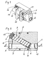
- eine perspektivische Ansicht eines Partikelzählers,
- Fig. 2
- einen Schnitt durch den Partikelzähler nach
Fig. 1 , aus dem der Aufbau eines in diesen integrierten Druckreduzierventils erkennbar ist.
- Fig. 1
- a perspective view of a particle counter,
- Fig. 2
- a section through the particle counter after
Fig. 1 , from which the structure of a built-in pressure reducing valve can be seen.
Der Partikelzähler ist in einer, in eine Flüssigkeits-, insbesondere Hydraulikflüssigkeitsleitung, einsetzbaren Messeinrichtung ausgebildet. Zuströmende Flüssigkeit strömt in einem Hauptstrom in eine Hauptströmungskanalöffnung 1 eines Hauptströmungskanales 2 ein und verlässt diesen Hauptströmungskanal 2 durch eine Hauptströmungskanal-Auslassöffnung 3.The particle counter is formed in a, in a liquid, in particular hydraulic fluid line, usable measuring device. Incoming liquid flows in a main flow into a main flow channel opening 1 of a main flow channel 2 and leaves this main flow channel 2 through a main flow channel outlet opening 3.
In den Hauptströmungskanal 2 ist ein federbelastetes Drosselventil 4 integriert. Dieses Drosselventil 4 umfasst einen, in einem Zylinder 5 verschiebbar gelagerten Kolben 6. Der Zylinder 5 ist dabei einenends mit einem geschlossenen Boden 7 in der Form eines Verschlussstopfens versehen und anderenends offen. Aus diesem offenen Ende des Zylinders 5 kann der Kolben 6 in den Strömungsweg des Hauptströmungskanales 2 eindringen und diesen Weg vollständig verschließen. Bei einem vollständigen Verschluss liegt der Kolben 6 an einem in dem Hauptströmungskanal 2 entsprechend angeordneten Ventilsitz 8 an. In Richtung auf eine Verschlusslage an dem Ventilsitz 8 ist der Kolben 6 durch eine im Inneren des Zylinders 5 angebrachte Feder 9 kraftbeaufschlagt. Die Feder 9 stützt sich dabei einenends an dem Kolben 6 und anderenends an dem Boden 7 des Zylinders ab. Die Achse des Zylinders 5, längs der sich der Kolben 6 bewegen kann, ist derart gegenüber der Längsachse des Hauptströmungskanales 2 geneigt, dass von der Einlassöffnung 1 in den Hauptströmungskanal 2 einströmende Flüssigkeit drosselventilöffnend auf die Stirnseite des Kolbens 6 einwirken kann. Dieser Öffnungskraft wirkt die Kraft der Feder 9, die hier als Druckfeder ausgebildet ist, entgegen. Die Durchströmungsrichtung des Hauptströmungskanales 2 ist mit Strömungspfeilen S gekennzeichnet. Stromab des Kolbens 6 des Drosselventils 4 ist der Hauptströmungskanal 2 über einen Verbindungskanal 10 in beispielsweise der Form eines Drosselkanals mit dem Inneren des Zylinders 5 druckausgleichend verbunden.In the main flow channel 2, a spring-loaded
Durch eine solche Ausbildung und Anordnung des Drosselventils 4 wird in dem Hauptströmungskanal 2 ein von dem Absolutdruck der dort strömenden Flüssigkeit unabhängiger, konstanter Druckabfall auf eine äußerst einfache Weise erzeugt und sicher gewährleistet.By such a design and arrangement of the
Die erfindungsgemäße Lichtschrankenmessung nach dem im Stand der Technik an sich hinreichend bekannten Abdunkelungs- bzw. Lichtblockadeverfahren erfolgt in einem Messkanal 11, der als ein das Drosselventil 4 überbrückender Bypass zu dem Hauptströmungskanal 2 ausgebildet ist. In der
Zwischen dem Messkanaleinlass 12 und dem Lichtschrankenbereich dieses Messkanales 11 im Bereich der Sensoreinrichtung 14 durchdringt dieser Messkanal 11 in seinem Zuleitungsbereich eine Heizeinrichtung 15. Innerhalb dieser Heizeinrichtung 15 wird die durchströmende Flüssigkeit auf einen vorgegebenen Temperaturwert außerhalb der möglichen Betriebstemperaturen erhitzt, wodurch diese Flüssigkeit die Sensoreinrichtung 14 stets mit einer gleichen, konstanten Temperatur durchströmt.Between the
Der elektronische Teil des Partikelzählers ist in der
Das Drosselventil 4 kann beispielsweise durch eine entsprechende Feder 9 für einen konstanten Druckabfall von 0,5 bar innerhalb des Hauptströmungskanales 2 ausgelegt sein. Der hierdurch und durch die Größe des Strömungsquerschnittes des Messkanales 11 festgelegte Messkanalvolumenstrom kann beispielsweise 50 ml/min betragen.The
Als Sensoreinrichtung 14 kann beispielsweise eine Einkanal-Lasereinrichtung eingesetzt werden. Die erzielbaren Messwerte und deren Auswertungsmöglichkeiten entsprechen dem bei gattungsgemäßen Partikelzählern allgemein bekannten Stand der Technik, weshalb hierauf bei der Beschreibung der vorliegenden Erfindung nicht im Einzelnen eingegangen werden muss.As a
Hingewiesen soll jedoch auf Folgendes werden.However, the following should be pointed out.
Mit Bezug auf den Einsatz eines Partikelzählers bei einer bestimmten, zu vermessenden Flüssigkeit ist jeweils eine Kalibrierung der Messeinrichtung mit einer auf die zu vermessenden Flüssigkeit abgestimmten Prüfflüssigkeit erforderlich. Diese Prüfflüssigkeit ist jeweils mit einem genau definierten Prüfstaub versetzt.With regard to the use of a particle counter for a specific liquid to be measured, a calibration of the measuring device with a test liquid adapted to the liquid to be measured is required in each case. Each test fluid is mixed with a precisely defined test dust.
Mit der erfindungsgemäßen Messeinrichtung ist es möglich, die Teilchengröße in einem Messfenster festzustellen, so dass die Auswertung des Messergebnisses durch einfaches Umschalten der Messeinrichtung auf voreingestellte Klassen von Partikelgrößen umgestellt werden kann. Das Umstellen kann durch die Elektronik automatisch erfolgen, so dass ein prinzipiell einkanaliges Messgerät durch wiederholtes Umschalten auf eine andere Messklasse wie ein Mehrkanalmessgerät arbeiten kann. Hierin besteht eine Besonderheit der vorliegenden Erfindung.With the measuring device according to the invention, it is possible to determine the particle size in a measuring window, so that the evaluation of the measurement result can be switched to preset classes of particle sizes by simply switching the measuring device. The switching can be done automatically by the electronics, so that a principle one-channel measuring device can work by repeatedly switching to another class such as a multi-channel measuring device. This is a special feature of the present invention.
Mit einer erfindungsgemäßen Messeinrichtung kann ohne weiteres eine Messgenauigkeit von mindestens etwa +/- 20 % gewährleistet werden.With a measuring device according to the invention, a measurement accuracy of at least about +/- 20% can be ensured without further ado.
Claims (4)
- Subsequent to the darkening or light-blocking process of an operating particle counter for counting foreign particles in a fluid stream, in particular in a hydraulic fluid stream, with a light barrier the light ray of which penetrates a measuring canal that can be flowed through by a bypass branch current of the fluid stream, and with evaluation electronics downstream from the receiver of the light barrier,
characterised by the features- the particle counter comprises a pressure-regulating device (4) that affects the fluid stream, said pressure-regulating device forcing, with a flowing fluid, the region, which is positioned between inlet and outlet of measuring canal (11) and contains the light barrier, a pressure difference that can be predefined and is independent of the flow properties of the primary fluid current,- the particle counter comprises a heating or a cooling device (15) for controlling the temperature of the branch current, which is flowing through the measuring canal (11), to a predeterminable temperature value,- the pressure-regulating device (4) is configured as a choke valve with a sealing body (6) that is impinged upon by a spring load and is positioned within the choke valve path, the opening and closing position of which being a function of the pressure difference existing on the upstream and downstream side thereof, wherein the spring load putting pressure on the sealing body (6) is directed against the dynamic pressure exerted on the upstream side on the sealing body (6) with a throttle effect. - The particle counter as specified in claim 1,
characterised by the features that- the sealing body is a piston (6) that is mounted in a displaceable manner in a cylinder (5),- the cylinder (5) limited on one end by a fixed cylinder floor (7) and is limited on the other end by the displaceable piston (6),- the piston (6), along with an end region that protrudes from the cylinder (5), dips into the fluid stream,- the piston (6) is loaded by the force of a spring (9) in the direction of a leaving of the cylinder (5),- the spring force is directed against a force that acts in a seal-opening manner on the fluid flowing against the piston (6),- the space of the cylinder (5) that is enclosed by the piston (6) is connected to the flow-off side of the piston (6) within the fluid stream by means of a connecting canal (10),- the pressure difference that is constantly present at the measuring canal (11) with a flowing fluid is determined by the force of the spring (9) impinging upon the piston (6). - The particle counter as specified in claim 1 or claim 2,
characterised in that
said particle counter comprises means for a remote indication of the measured values. - The particle counter as specified in claim 3,
characterised in that
said particle counter comprises means for a telemetric remote indication of the measured values.
Applications Claiming Priority (1)
| Application Number | Priority Date | Filing Date | Title |
|---|---|---|---|
| DE102005016761A DE102005016761A1 (en) | 2005-04-11 | 2005-04-11 | Particle counter for foreign particles in a liquid stream |
Publications (2)
| Publication Number | Publication Date |
|---|---|
| EP1712894A1 EP1712894A1 (en) | 2006-10-18 |
| EP1712894B1 true EP1712894B1 (en) | 2009-09-09 |
Family
ID=36297336
Family Applications (1)
| Application Number | Title | Priority Date | Filing Date |
|---|---|---|---|
| EP06111901A Expired - Fee Related EP1712894B1 (en) | 2005-04-11 | 2006-03-29 | Particle counter for foreign particles in a liquid flow |
Country Status (3)
| Country | Link |
|---|---|
| US (1) | US7382452B2 (en) |
| EP (1) | EP1712894B1 (en) |
| DE (2) | DE102005016761A1 (en) |
Families Citing this family (2)
| Publication number | Priority date | Publication date | Assignee | Title |
|---|---|---|---|---|
| ATE498132T1 (en) * | 2006-12-18 | 2011-02-15 | Airbus Operations Sas | DEVICE AND METHOD FOR MONITORING PARTICLE CONTAMINATION IN FLOWING HYDRAULIC FLUIDS |
| ES2646732B2 (en) * | 2017-03-29 | 2018-07-30 | Universidad De Cantabria | Portable device for monitoring, testing, incorporation of additives and control of pipes, materials and fluids |
Family Cites Families (13)
| Publication number | Priority date | Publication date | Assignee | Title |
|---|---|---|---|---|
| US3632210A (en) * | 1969-06-19 | 1972-01-04 | Environment One Corp | Variable rate continuous flow condensation nuclei meter having adjustable expansion period and improved gain |
| DE2062698A1 (en) * | 1970-12-19 | 1972-06-29 | Teves Gmbh Alfred | Method and device for determining the wear and tear on hydraulic units |
| GB1471527A (en) * | 1973-06-14 | 1977-04-27 | Coulter Electronics Ld | On-line system for monitoring particles in fluids |
| DE8912584U1 (en) * | 1989-10-24 | 1989-12-07 | Hydac Technology Gmbh, 6603 Sulzbach, De | |
| DE4110231C2 (en) * | 1991-03-28 | 1995-01-05 | Knecht Filterwerke Gmbh | Measuring device for determining the dirt particle content of liquids |
| US5118959A (en) * | 1991-05-03 | 1992-06-02 | Tsi Incorporated | Water separation system for condensation particle counter |
| US5379791A (en) * | 1993-09-03 | 1995-01-10 | Christopher; John F. | Dual-head flow controller and method |
| DE19627587C2 (en) * | 1996-07-09 | 1999-02-04 | Hydac Filtertechnik Gmbh | Device for monitoring the performance properties of fluids, in particular hydraulic fluids in fluid power systems |
| DE19735066C1 (en) * | 1997-08-13 | 1999-01-28 | Hydac Filtertechnik Gmbh | Particle counter evaluation method |
| DE10127021C1 (en) * | 2001-06-01 | 2003-02-20 | Hydac Filtertechnik Gmbh | Filter element soiling level indication device detects movement of spring-loaded piston subjected to pressures of hydraulic oil on dirty and clean sides of filter on opposite sides |
| US6912479B2 (en) * | 2002-12-26 | 2005-06-28 | Volvo Construction Equipment Holding Sweden Ab | Heavy equipment having oil pollution degree diagnosing function, and oil pollution degree measuring system on network using the same, and operation method |
| DE10343457C5 (en) * | 2003-09-19 | 2012-01-12 | Hydac Filtertechnik Gmbh | Device for particle measurement |
| KR100614101B1 (en) * | 2005-09-15 | 2006-08-22 | 한국과학기술연구원 | Particle counter |
-
2005
- 2005-04-11 DE DE102005016761A patent/DE102005016761A1/en not_active Withdrawn
-
2006
- 2006-03-29 DE DE502006004770T patent/DE502006004770D1/en active Active
- 2006-03-29 EP EP06111901A patent/EP1712894B1/en not_active Expired - Fee Related
- 2006-04-11 US US11/402,073 patent/US7382452B2/en not_active Expired - Fee Related
Also Published As
| Publication number | Publication date |
|---|---|
| US20060227926A1 (en) | 2006-10-12 |
| DE102005016761A1 (en) | 2006-10-12 |
| EP1712894A1 (en) | 2006-10-18 |
| DE502006004770D1 (en) | 2009-10-22 |
| US7382452B2 (en) | 2008-06-03 |
Similar Documents
| Publication | Publication Date | Title |
|---|---|---|
| DE3012059C2 (en) | ||
| EP0797080A2 (en) | Flow control valve with flowmeter | |
| WO2018050803A1 (en) | Fluid meter | |
| DE202008003055U1 (en) | Pressure reducer filter Arrangement with leakage protection | |
| DE102008062521A1 (en) | Flow sensor for fluid media | |
| EP1904812A1 (en) | Ram pressure probe | |
| EP1712894B1 (en) | Particle counter for foreign particles in a liquid flow | |
| DE2351940A1 (en) | PRESSURE MEASURING PROBE | |
| DE10038874A1 (en) | Valve for regulating and measuring the flow rate of a fluid | |
| WO2010108572A1 (en) | Fireproof ceramic plug | |
| EP0777109A2 (en) | Apparatus for determining the force of a volumetric gas flow | |
| EP0943901B1 (en) | Fitting for a liquid flowmeter | |
| DE102005006478B4 (en) | distribution valve | |
| DE202014101518U1 (en) | Device for field flow fractionation | |
| DE102008032309B4 (en) | Sensor arrangement for measuring the state of a liquid, in particular of oil | |
| DE10259395A1 (en) | Connector for fluid lines | |
| EP1622694B1 (en) | Leakage indicator for a filter element of a filter press | |
| DE2021782C3 (en) | Volume measuring device | |
| DE102014014730B4 (en) | Clogging indicator | |
| DE202020003961U1 (en) | Leak detection device for detecting a leak in a system carrying a fluid | |
| EP2833038B1 (en) | Valve for field sensitive liquids and hydraulic system with such a valve | |
| AT11330U1 (en) | ARRANGEMENT WITH AT LEAST ONE FLUID FLOW MEASURING DEVICE | |
| DE102006047880B4 (en) | flow adjustment | |
| WO2009080353A2 (en) | Device for monitoring a free-flowing medium | |
| DE10255522B4 (en) | Valve with flow meter |
Legal Events
| Date | Code | Title | Description |
|---|---|---|---|
| PUAI | Public reference made under article 153(3) epc to a published international application that has entered the european phase |
Free format text: ORIGINAL CODE: 0009012 |
|
| 17P | Request for examination filed |
Effective date: 20060902 |
|
| AK | Designated contracting states |
Kind code of ref document: A1 Designated state(s): AT BE BG CH CY CZ DE DK EE ES FI FR GB GR HU IE IS IT LI LT LU LV MC NL PL PT RO SE SI SK TR |
|
| AX | Request for extension of the european patent |
Extension state: AL BA HR MK YU |
|
| AKX | Designation fees paid |
Designated state(s): DE FR GB |
|
| GRAP | Despatch of communication of intention to grant a patent |
Free format text: ORIGINAL CODE: EPIDOSNIGR1 |
|
| GRAS | Grant fee paid |
Free format text: ORIGINAL CODE: EPIDOSNIGR3 |
|
| GRAA | (expected) grant |
Free format text: ORIGINAL CODE: 0009210 |
|
| AK | Designated contracting states |
Kind code of ref document: B1 Designated state(s): DE FR GB |
|
| REG | Reference to a national code |
Ref country code: GB Ref legal event code: FG4D Free format text: NOT ENGLISH |
|
| REF | Corresponds to: |
Ref document number: 502006004770 Country of ref document: DE Date of ref document: 20091022 Kind code of ref document: P |
|
| PLBE | No opposition filed within time limit |
Free format text: ORIGINAL CODE: 0009261 |
|
| STAA | Information on the status of an ep patent application or granted ep patent |
Free format text: STATUS: NO OPPOSITION FILED WITHIN TIME LIMIT |
|
| 26N | No opposition filed |
Effective date: 20100610 |
|
| REG | Reference to a national code |
Ref country code: FR Ref legal event code: PLFP Year of fee payment: 11 |
|
| REG | Reference to a national code |
Ref country code: DE Ref legal event code: R082 Ref document number: 502006004770 Country of ref document: DE Representative=s name: BRP RENAUD UND PARTNER MBB RECHTSANWAELTE PATE, DE Ref country code: DE Ref legal event code: R082 Ref document number: 502006004770 Country of ref document: DE Representative=s name: BRP RENAUD UND PARTNER MBB, DE Ref country code: DE Ref legal event code: R081 Ref document number: 502006004770 Country of ref document: DE Owner name: FILTRATION GROUP GMBH, DE Free format text: FORMER OWNER: MAHLE INTERNATIONAL GMBH, 70376 STUTTGART, DE Ref country code: DE Ref legal event code: R081 Ref document number: 502006004770 Country of ref document: DE Owner name: MAHLE INDUSTRIEFILTRATION GMBH, DE Free format text: FORMER OWNER: MAHLE INTERNATIONAL GMBH, 70376 STUTTGART, DE |
|
| REG | Reference to a national code |
Ref country code: FR Ref legal event code: PLFP Year of fee payment: 12 |
|
| REG | Reference to a national code |
Ref country code: GB Ref legal event code: 732E Free format text: REGISTERED BETWEEN 20170331 AND 20170405 |
|
| REG | Reference to a national code |
Ref country code: FR Ref legal event code: TP Owner name: MAHLE INTERNATIONAL GMBH, DE Effective date: 20170531 |
|
| REG | Reference to a national code |
Ref country code: DE Ref legal event code: R082 Ref document number: 502006004770 Country of ref document: DE Representative=s name: BRP RENAUD UND PARTNER MBB RECHTSANWAELTE PATE, DE Ref country code: DE Ref legal event code: R081 Ref document number: 502006004770 Country of ref document: DE Owner name: FILTRATION GROUP GMBH, DE Free format text: FORMER OWNER: MAHLE INDUSTRIEFILTRATION GMBH, 74613 OEHRINGEN, DE |
|
| REG | Reference to a national code |
Ref country code: FR Ref legal event code: PLFP Year of fee payment: 13 |
|
| REG | Reference to a national code |
Ref country code: FR Ref legal event code: CD Owner name: FILTRATION GROUP GMBH, DE Effective date: 20180423 |
|
| PGFP | Annual fee paid to national office [announced via postgrant information from national office to epo] |
Ref country code: DE Payment date: 20180530 Year of fee payment: 13 |
|
| PGFP | Annual fee paid to national office [announced via postgrant information from national office to epo] |
Ref country code: GB Payment date: 20190327 Year of fee payment: 14 |
|
| REG | Reference to a national code |
Ref country code: DE Ref legal event code: R119 Ref document number: 502006004770 Country of ref document: DE |
|
| PGFP | Annual fee paid to national office [announced via postgrant information from national office to epo] |
Ref country code: FR Payment date: 20190903 Year of fee payment: 14 |
|
| PG25 | Lapsed in a contracting state [announced via postgrant information from national office to epo] |
Ref country code: DE Free format text: LAPSE BECAUSE OF NON-PAYMENT OF DUE FEES Effective date: 20191001 |
|
| PG25 | Lapsed in a contracting state [announced via postgrant information from national office to epo] |
Ref country code: FR Free format text: LAPSE BECAUSE OF NON-PAYMENT OF DUE FEES Effective date: 20200331 |
|
| GBPC | Gb: european patent ceased through non-payment of renewal fee |
Effective date: 20200329 |
|
| PG25 | Lapsed in a contracting state [announced via postgrant information from national office to epo] |
Ref country code: GB Free format text: LAPSE BECAUSE OF NON-PAYMENT OF DUE FEES Effective date: 20200329 |