EP1712800A1 - Roue de ventilateur - Google Patents
Roue de ventilateur Download PDFInfo
- Publication number
- EP1712800A1 EP1712800A1 EP06007889A EP06007889A EP1712800A1 EP 1712800 A1 EP1712800 A1 EP 1712800A1 EP 06007889 A EP06007889 A EP 06007889A EP 06007889 A EP06007889 A EP 06007889A EP 1712800 A1 EP1712800 A1 EP 1712800A1
- Authority
- EP
- European Patent Office
- Prior art keywords
- ring
- fan wheel
- wheel according
- hub
- profiling
- Prior art date
- Legal status (The legal status is an assumption and is not a legal conclusion. Google has not performed a legal analysis and makes no representation as to the accuracy of the status listed.)
- Granted
Links
- 230000002093 peripheral effect Effects 0.000 claims description 7
- 230000000295 complement effect Effects 0.000 claims description 4
- 230000006641 stabilisation Effects 0.000 description 4
- 238000011105 stabilization Methods 0.000 description 4
- 238000006073 displacement reaction Methods 0.000 description 3
- 230000000694 effects Effects 0.000 description 3
- 230000001133 acceleration Effects 0.000 description 2
- 238000001816 cooling Methods 0.000 description 2
- 238000011161 development Methods 0.000 description 1
- 230000018109 developmental process Effects 0.000 description 1
- 238000002474 experimental method Methods 0.000 description 1
- 238000002347 injection Methods 0.000 description 1
- 239000007924 injection Substances 0.000 description 1
- 238000004519 manufacturing process Methods 0.000 description 1
- 230000003763 resistance to breakage Effects 0.000 description 1
- 239000003381 stabilizer Substances 0.000 description 1
- 230000000087 stabilizing effect Effects 0.000 description 1
Images
Classifications
-
- F—MECHANICAL ENGINEERING; LIGHTING; HEATING; WEAPONS; BLASTING
- F04—POSITIVE - DISPLACEMENT MACHINES FOR LIQUIDS; PUMPS FOR LIQUIDS OR ELASTIC FLUIDS
- F04D—NON-POSITIVE-DISPLACEMENT PUMPS
- F04D29/00—Details, component parts, or accessories
- F04D29/26—Rotors specially for elastic fluids
- F04D29/32—Rotors specially for elastic fluids for axial flow pumps
- F04D29/325—Rotors specially for elastic fluids for axial flow pumps for axial flow fans
- F04D29/326—Rotors specially for elastic fluids for axial flow pumps for axial flow fans comprising a rotating shroud
-
- F—MECHANICAL ENGINEERING; LIGHTING; HEATING; WEAPONS; BLASTING
- F04—POSITIVE - DISPLACEMENT MACHINES FOR LIQUIDS; PUMPS FOR LIQUIDS OR ELASTIC FLUIDS
- F04D—NON-POSITIVE-DISPLACEMENT PUMPS
- F04D29/00—Details, component parts, or accessories
- F04D29/66—Combating cavitation, whirls, noise, vibration or the like; Balancing
- F04D29/661—Combating cavitation, whirls, noise, vibration or the like; Balancing especially adapted for elastic fluid pumps
- F04D29/662—Balancing of rotors
Definitions
- the invention relates to a fan with a hub and with a plurality of radially outwardly extending from the hub wings and with a coaxial with the hub and radially disposed between the hub and the outer diameter of the impeller ring.
- Generic fan wheels are often used for cooling and dissipation of the resulting heat loss in electric motors and their electronic components.
- a generic fan is, for example, from the EP 0 761 979 A1 known.
- the fan has a coaxial with the hub and radially disposed between the hub and the outer diameter of the impeller, ring on. This contributes to the stabilization of the fan wheel and the stiffening of the circumferentially spaced wings.
- the known fan wheel has, in addition to the ring on a second ring which extends along the outer diameter of the fan wheel. The document does not explain how balancing weights can be attached to the fan wheel. Balancing the fan wheel, however, is desirable to extend the life and reduce running noise.
- the DE 1 960 505 shows a device for balancing the impellers of air blowers. From the document it is known to provide circumferentially displaceable balance weights on the wings of the air blower.
- brackets are provided with a peripheral ring provided on the outer diameter, in which for balancing purposes formed as brackets balancing weights are attached to the smooth peripheral ring.
- the disadvantage here is that the brackets can be moved in an acceleration of the fan in your position.
- the invention is based on the object to form a fan so that it is stable and on the other hand with good results ausuchtbar.
- the invention is based on the idea to provide means for the defined attachment of balancing weights in different positions on a stabilizing or stiffening ring, which is radially spaced both from the outer diameter of the fan wheel and from the hub.
- a stabilizing or stiffening ring which is radially spaced both from the outer diameter of the fan wheel and from the hub.
- Another advantage of the invention is that the negative effects of weight tolerances of the balance weights less significant on the balancing result than if the balancing weights were attached to the outer diameter of the fan wheel.
- a particularly expedient embodiment is provided by the fact that the defined attachment positions are formed by a profiling of the ring. If the fan is made of plastic as an injection molded part, the profiling can be formed directly in the manufacture of the fan wheel.
- the profiling of the ring is designed as sawtooth profiling.
- the angles of all flanks to the ring should be the same size.
- a balancing weight designed as a clamp can be clamped between the saw teeth. Due to the sloping flanks of the profiling a displacement of the clip in the circumferential direction is not possible.
- Another possibility for fastening is to form the balance weights complementary to the profile in order to achieve an improved positive connection between profiling and balancing weights.
- the profiling is provided on the outside of the ring. Due to the large circumference on the outside of the ring, a plurality of defined mounting positions can be provided on the ring. Of course, it is also conceivable, additionally or alternatively, to provide a profiling on the side of the ring facing the hub and / or on its side surfaces.
- the mounting positions are formed as mounting holes distributed over the circumference of the ring. With appropriate design of the balancing weights they can be inserted into the holes and secured therein. Thus, a subsequent displacement of the balance weights is avoided.
- the balance weights can also be accommodated in receiving pockets distributed over the circumference of the ring.
- a good delivery rate is achieved when the wings extend continuously from the hub to the outer diameter of the fan wheel.
- the wings are divided into two groups of wings, namely a first group of wings, which extends radially between the hub and the ring, and a second group, which extends radially between the Ring and the outer diameter of the fan wheel extends.
- the wings of different groups can be arranged offset from one another in the circumferential direction.
- the wings are mounted directly on the shaft of an electric motor, so if the hub is formed by the shaft. In this way, the fan can be particularly easily formed integrally with the shaft, whereby the provision of a separate hub is avoided.
- the balancing weight can be fastened detachably, that is, for example, designed as a bendable clamp.
- the balancing weight is complementary in shape to a peripheral portion of the profiling.
- this second ring is ideally arranged on the outer diameter of the fan wheel.
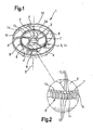
- a fan 1 is shown made of plastic.
- the fan 1 can be used for example for cooling of electric motors and their electronic components.
- the fan wheel 1 is arranged with an in the center of a hub 2, axially enjoyingrekkenden Mounting hole 3 is placed on the shaft of a motor and secured against rotation relative to the shaft.
- the fan 1 has five evenly distributed over the circumference, extending from the hub 2 radially outwardly extending wings 4. All wings 4 are designed identically, curved in the circumferential direction and employed at an angle to the central axis 5 of the fan wheel 1.
- closed ring 7 is provided for stabilization and stiffening of the wings 4 a integrally formed with the wings 4, closed ring 7 is provided.
- the flat, circular ring 7 extends in the circumferential direction and is arranged coaxially to the hub 2 and radially between the hub 2 and the outer diameter 6 of the fan wheel 1.
- the ring 7 can widen immediately adjacent to the wings to about the width of the wings 4, whereby the stability and the resistance to breakage of the fan wheel 1 is increased.
- the diameter of the ring 7 corresponds in the illustrated embodiment about half the fan diameter, but can also be selected smaller or larger depending on the wheel diameter.
- the ring 7 On its outer side 8, the ring 7 is provided with a sawtooth-like profiling 9 with circumferentially alternating teeth 10 and tooth spaces 11.
- the tooth gaps 11 define attachment positions 12 for attachment of balance weights, not shown.
- balancing weights for example Metällklammem can be used, which are inserted into one or more tooth gaps 11 laterally and abut the inner side 13 and on the outer side 8 of the ring 7 and clamp this.
- the profiling 9 is designed such that the teeth 10 form triangular triangles. It is particularly advantageous if the balance weights for forming a positive connection with the ring 7, at least in partial sections, are complementary in shape to the profiling 9, ie have at least one tooth 10 or one tooth gap 11 in the present case.
- the profiling 9 is provided exclusively on itself between the wings 4 extending peripheral portions 14 of the ring 7.
- the wings 4 of the fan wheel 1 extend continuously from the hub 2 to the outer diameter 6 of the fan wheel 1. Along the outer periphery of the fan wheel 1 extends second, closed ring 15. This additionally increases the stability and rigidity of the fan wheel 1 and closes this radially outward.
- a section of the fan wheel 1 is shown enlarged.
- the depth of the tooth gaps 11 corresponds to about a quarter of the thickness of the ring. 7
Landscapes
- Engineering & Computer Science (AREA)
- Mechanical Engineering (AREA)
- General Engineering & Computer Science (AREA)
- Structures Of Non-Positive Displacement Pumps (AREA)
Applications Claiming Priority (1)
| Application Number | Priority Date | Filing Date | Title |
|---|---|---|---|
| DE200520006043 DE202005006043U1 (de) | 2005-04-14 | 2005-04-14 | Lüfterrad |
Publications (2)
| Publication Number | Publication Date |
|---|---|
| EP1712800A1 true EP1712800A1 (fr) | 2006-10-18 |
| EP1712800B1 EP1712800B1 (fr) | 2010-10-27 |
Family
ID=34877884
Family Applications (1)
| Application Number | Title | Priority Date | Filing Date |
|---|---|---|---|
| EP06007889A Active EP1712800B1 (fr) | 2005-04-14 | 2006-04-13 | Roue de ventilateur |
Country Status (6)
| Country | Link |
|---|---|
| US (1) | US20060233646A1 (fr) |
| EP (1) | EP1712800B1 (fr) |
| AT (1) | ATE486223T1 (fr) |
| DE (2) | DE202005006043U1 (fr) |
| ES (1) | ES2354656T3 (fr) |
| PT (1) | PT1712800E (fr) |
Cited By (10)
| Publication number | Priority date | Publication date | Assignee | Title |
|---|---|---|---|---|
| US9645584B2 (en) | 2014-09-17 | 2017-05-09 | Honeywell International Inc. | Gas valve with electronic health monitoring |
| US9657946B2 (en) | 2012-09-15 | 2017-05-23 | Honeywell International Inc. | Burner control system |
| US9683674B2 (en) | 2013-10-29 | 2017-06-20 | Honeywell Technologies Sarl | Regulating device |
| US9835265B2 (en) | 2011-12-15 | 2017-12-05 | Honeywell International Inc. | Valve with actuator diagnostics |
| US9841122B2 (en) | 2014-09-09 | 2017-12-12 | Honeywell International Inc. | Gas valve with electronic valve proving system |
| US9846440B2 (en) | 2011-12-15 | 2017-12-19 | Honeywell International Inc. | Valve controller configured to estimate fuel comsumption |
| US9851103B2 (en) | 2011-12-15 | 2017-12-26 | Honeywell International Inc. | Gas valve with overpressure diagnostics |
| US10422531B2 (en) | 2012-09-15 | 2019-09-24 | Honeywell International Inc. | System and approach for controlling a combustion chamber |
| US10503181B2 (en) | 2016-01-13 | 2019-12-10 | Honeywell International Inc. | Pressure regulator |
| US11884128B2 (en) | 2017-12-18 | 2024-01-30 | Carrier Corporation | Fan stator construction to minimize axial depth |
Families Citing this family (19)
| Publication number | Priority date | Publication date | Assignee | Title |
|---|---|---|---|---|
| DE102005054251B4 (de) * | 2005-11-11 | 2015-01-15 | Sew-Eurodrive Gmbh & Co Kg | Elektromotor |
| CN101139996B (zh) * | 2006-09-07 | 2012-01-04 | 台达电子工业股份有限公司 | 风扇及其叶轮 |
| US20100316498A1 (en) * | 2008-02-22 | 2010-12-16 | Horton, Inc. | Fan manufacturing and assembly |
| US20120219419A1 (en) * | 2011-02-28 | 2012-08-30 | Wen-Hao Liu | Round axial fan with balancing structure |
| US9995486B2 (en) | 2011-12-15 | 2018-06-12 | Honeywell International Inc. | Gas valve with high/low gas pressure detection |
| US9074770B2 (en) | 2011-12-15 | 2015-07-07 | Honeywell International Inc. | Gas valve with electronic valve proving system |
| US8905063B2 (en) | 2011-12-15 | 2014-12-09 | Honeywell International Inc. | Gas valve with fuel rate monitor |
| US9557059B2 (en) | 2011-12-15 | 2017-01-31 | Honeywell International Inc | Gas valve with communication link |
| US8839815B2 (en) | 2011-12-15 | 2014-09-23 | Honeywell International Inc. | Gas valve with electronic cycle counter |
| US8947242B2 (en) | 2011-12-15 | 2015-02-03 | Honeywell International Inc. | Gas valve with valve leakage test |
| US8899264B2 (en) | 2011-12-15 | 2014-12-02 | Honeywell International Inc. | Gas valve with electronic proof of closure system |
| ITBO20120042A1 (it) * | 2012-01-31 | 2013-08-01 | Comex Europ S R L | Dispositivo a ventola |
| US9200637B2 (en) | 2012-10-31 | 2015-12-01 | Apple Inc. | Method for correction of impeller unbalance of a cooling fan |
| CN203453120U (zh) * | 2013-09-03 | 2014-02-26 | 讯凯国际股份有限公司 | 风扇及其风扇叶轮 |
| US10024439B2 (en) | 2013-12-16 | 2018-07-17 | Honeywell International Inc. | Valve over-travel mechanism |
| US10564062B2 (en) | 2016-10-19 | 2020-02-18 | Honeywell International Inc. | Human-machine interface for gas valve |
| CN106640758B (zh) * | 2017-01-16 | 2023-03-14 | 广东美的制冷设备有限公司 | 一种双风道风轮 |
| US11073281B2 (en) | 2017-12-29 | 2021-07-27 | Honeywell International Inc. | Closed-loop programming and control of a combustion appliance |
| US10697815B2 (en) | 2018-06-09 | 2020-06-30 | Honeywell International Inc. | System and methods for mitigating condensation in a sensor module |
Citations (5)
| Publication number | Priority date | Publication date | Assignee | Title |
|---|---|---|---|---|
| US5380156A (en) * | 1993-04-12 | 1995-01-10 | Iacovino; Robert | Ceiling fan balance apparatus |
| EP0921319A2 (fr) * | 1997-12-08 | 1999-06-09 | Harvard Industries, Inc. | Ventilateur en plastique et embrayage thermique |
| US6156090A (en) * | 1997-10-03 | 2000-12-05 | Hitachi, Ltd. | Air cleaner having vanes with a winglike cross-section between a shroud and baseplate for rotation within a housing |
| EP1111245A2 (fr) * | 1999-12-23 | 2001-06-27 | BorgWarner Inc. | Ventilateur de refroidissement moulé |
| US6358009B1 (en) * | 1999-12-30 | 2002-03-19 | American Cooling Systems, Llc | Fan blade assembly and method of balancing the same |
Family Cites Families (4)
| Publication number | Priority date | Publication date | Assignee | Title |
|---|---|---|---|---|
| JPS5688992A (en) * | 1979-12-21 | 1981-07-18 | Aisin Seiki Co Ltd | Axial fan for cooling internal combustion engine |
| GB2161109B (en) * | 1984-07-07 | 1988-12-21 | Rolls Royce | Integral bladed member |
| DE4122018C2 (de) * | 1991-07-03 | 1993-12-23 | Licentia Gmbh | Axialgebläse, insbesondere zur Kühlung eines dem Kühler eines Fahrzeugs vorgeordneten Kondensators einer Klimaanlage |
| CN1288349C (zh) * | 2003-03-28 | 2006-12-06 | 三星电子株式会社 | 轴流式风扇组件 |
-
2005
- 2005-04-14 DE DE200520006043 patent/DE202005006043U1/de not_active Expired - Lifetime
-
2006
- 2006-04-11 US US11/402,323 patent/US20060233646A1/en not_active Abandoned
- 2006-04-13 PT PT06007889T patent/PT1712800E/pt unknown
- 2006-04-13 EP EP06007889A patent/EP1712800B1/fr active Active
- 2006-04-13 DE DE502006008160T patent/DE502006008160D1/de active Active
- 2006-04-13 ES ES06007889T patent/ES2354656T3/es active Active
- 2006-04-13 AT AT06007889T patent/ATE486223T1/de active
Patent Citations (5)
| Publication number | Priority date | Publication date | Assignee | Title |
|---|---|---|---|---|
| US5380156A (en) * | 1993-04-12 | 1995-01-10 | Iacovino; Robert | Ceiling fan balance apparatus |
| US6156090A (en) * | 1997-10-03 | 2000-12-05 | Hitachi, Ltd. | Air cleaner having vanes with a winglike cross-section between a shroud and baseplate for rotation within a housing |
| EP0921319A2 (fr) * | 1997-12-08 | 1999-06-09 | Harvard Industries, Inc. | Ventilateur en plastique et embrayage thermique |
| EP1111245A2 (fr) * | 1999-12-23 | 2001-06-27 | BorgWarner Inc. | Ventilateur de refroidissement moulé |
| US6358009B1 (en) * | 1999-12-30 | 2002-03-19 | American Cooling Systems, Llc | Fan blade assembly and method of balancing the same |
Cited By (11)
| Publication number | Priority date | Publication date | Assignee | Title |
|---|---|---|---|---|
| US9835265B2 (en) | 2011-12-15 | 2017-12-05 | Honeywell International Inc. | Valve with actuator diagnostics |
| US9846440B2 (en) | 2011-12-15 | 2017-12-19 | Honeywell International Inc. | Valve controller configured to estimate fuel comsumption |
| US9851103B2 (en) | 2011-12-15 | 2017-12-26 | Honeywell International Inc. | Gas valve with overpressure diagnostics |
| US9657946B2 (en) | 2012-09-15 | 2017-05-23 | Honeywell International Inc. | Burner control system |
| US10422531B2 (en) | 2012-09-15 | 2019-09-24 | Honeywell International Inc. | System and approach for controlling a combustion chamber |
| US11421875B2 (en) | 2012-09-15 | 2022-08-23 | Honeywell International Inc. | Burner control system |
| US9683674B2 (en) | 2013-10-29 | 2017-06-20 | Honeywell Technologies Sarl | Regulating device |
| US9841122B2 (en) | 2014-09-09 | 2017-12-12 | Honeywell International Inc. | Gas valve with electronic valve proving system |
| US9645584B2 (en) | 2014-09-17 | 2017-05-09 | Honeywell International Inc. | Gas valve with electronic health monitoring |
| US10503181B2 (en) | 2016-01-13 | 2019-12-10 | Honeywell International Inc. | Pressure regulator |
| US11884128B2 (en) | 2017-12-18 | 2024-01-30 | Carrier Corporation | Fan stator construction to minimize axial depth |
Also Published As
| Publication number | Publication date |
|---|---|
| EP1712800B1 (fr) | 2010-10-27 |
| DE202005006043U1 (de) | 2005-08-18 |
| ES2354656T3 (es) | 2011-03-16 |
| PT1712800E (pt) | 2011-01-14 |
| ATE486223T1 (de) | 2010-11-15 |
| DE502006008160D1 (de) | 2010-12-09 |
| US20060233646A1 (en) | 2006-10-19 |
Similar Documents
| Publication | Publication Date | Title |
|---|---|---|
| EP1712800B1 (fr) | Roue de ventilateur | |
| EP1934483B1 (fr) | Roue de ventilateur | |
| DE4136293B4 (de) | Laufrad für ein Gebläse, insbesondere Radialgebläse | |
| EP2242930B1 (fr) | Ventilateur compact | |
| EP2823184B1 (fr) | Ventilateur axial | |
| EP2737189B1 (fr) | Module ventilateur de radiateur | |
| DE102006057087B3 (de) | Laufrad für ein Gebläse | |
| DE102013109577A1 (de) | Gebläsemodul für einen Wärmetauscher | |
| WO2008015233A1 (fr) | Aube de ventilateur | |
| DE202012103554U1 (de) | Laufrad mit Wuchtausgleich | |
| EP2771581B1 (fr) | Roue de ventilateur axial | |
| WO2017017264A1 (fr) | Roue de ventilateur et module ventilateur de refroidissement | |
| EP3165773A1 (fr) | Dispositif convoyeur | |
| WO2021115806A1 (fr) | Roue à aubes pour rotor, et machine électrique | |
| EP3367541A1 (fr) | Rotor d'un moteur électrique | |
| EP3176920B1 (fr) | Dispositif de couvercle pour un boîtier électronique d'un moteur électrique | |
| EP2329149B1 (fr) | Ventilateur diagonal | |
| DE102010028099A1 (de) | Axiallüfter | |
| DE102009028745A1 (de) | Entkopplung eines Antriebsmotors | |
| DE202007005784U1 (de) | Lüftungseinheit zur Fremdbelüftung eines Elektromotors | |
| EP3273066A1 (fr) | Roue de ventilateur | |
| EP3872351A1 (fr) | Roue d'un ventilateur axial ou diagonal pourvue d'une bague d'équilibrage | |
| DE102004031159B4 (de) | Gebläsevorrichtung | |
| EP2971788B1 (fr) | Flasque pour moteur d'un ventilateur centrifuge d'une hotte aspirante | |
| DE10111292A1 (de) | Lüfteranordnung für eine elektrische Maschine |
Legal Events
| Date | Code | Title | Description |
|---|---|---|---|
| PUAI | Public reference made under article 153(3) epc to a published international application that has entered the european phase |
Free format text: ORIGINAL CODE: 0009012 |
|
| AK | Designated contracting states |
Kind code of ref document: A1 Designated state(s): AT BE BG CH CY CZ DE DK EE ES FI FR GB GR HU IE IS IT LI LT LU LV MC NL PL PT RO SE SI SK TR |
|
| AX | Request for extension of the european patent |
Extension state: AL BA HR MK YU |
|
| 17P | Request for examination filed |
Effective date: 20070416 |
|
| 17Q | First examination report despatched |
Effective date: 20070516 |
|
| AKX | Designation fees paid |
Designated state(s): AT BE BG CH CY CZ DE DK EE ES FI FR GB GR HU IE IS IT LI LT LU LV MC NL PL PT RO SE SI SK TR |
|
| GRAP | Despatch of communication of intention to grant a patent |
Free format text: ORIGINAL CODE: EPIDOSNIGR1 |
|
| GRAS | Grant fee paid |
Free format text: ORIGINAL CODE: EPIDOSNIGR3 |
|
| GRAA | (expected) grant |
Free format text: ORIGINAL CODE: 0009210 |
|
| AK | Designated contracting states |
Kind code of ref document: B1 Designated state(s): AT BE BG CH CY CZ DE DK EE ES FI FR GB GR HU IE IS IT LI LT LU LV MC NL PL PT RO SE SI SK TR |
|
| REG | Reference to a national code |
Ref country code: GB Ref legal event code: FG4D Free format text: NOT ENGLISH |
|
| REG | Reference to a national code |
Ref country code: CH Ref legal event code: EP |
|
| REG | Reference to a national code |
Ref country code: IE Ref legal event code: FG4D Free format text: LANGUAGE OF EP DOCUMENT: GERMAN |
|
| REF | Corresponds to: |
Ref document number: 502006008160 Country of ref document: DE Date of ref document: 20101209 Kind code of ref document: P |
|
| REG | Reference to a national code |
Ref country code: PT Ref legal event code: SC4A Free format text: AVAILABILITY OF NATIONAL TRANSLATION Effective date: 20110107 |
|
| REG | Reference to a national code |
Ref country code: NL Ref legal event code: T3 |
|
| REG | Reference to a national code |
Ref country code: ES Ref legal event code: FG2A Effective date: 20110304 |
|
| LTIE | Lt: invalidation of european patent or patent extension |
Effective date: 20101027 |
|
| PG25 | Lapsed in a contracting state [announced via postgrant information from national office to epo] |
Ref country code: LT Free format text: LAPSE BECAUSE OF FAILURE TO SUBMIT A TRANSLATION OF THE DESCRIPTION OR TO PAY THE FEE WITHIN THE PRESCRIBED TIME-LIMIT Effective date: 20101027 |
|
| REG | Reference to a national code |
Ref country code: IE Ref legal event code: FD4D |
|
| PG25 | Lapsed in a contracting state [announced via postgrant information from national office to epo] |
Ref country code: SE Free format text: LAPSE BECAUSE OF FAILURE TO SUBMIT A TRANSLATION OF THE DESCRIPTION OR TO PAY THE FEE WITHIN THE PRESCRIBED TIME-LIMIT Effective date: 20101027 Ref country code: SI Free format text: LAPSE BECAUSE OF FAILURE TO SUBMIT A TRANSLATION OF THE DESCRIPTION OR TO PAY THE FEE WITHIN THE PRESCRIBED TIME-LIMIT Effective date: 20101027 Ref country code: BG Free format text: LAPSE BECAUSE OF FAILURE TO SUBMIT A TRANSLATION OF THE DESCRIPTION OR TO PAY THE FEE WITHIN THE PRESCRIBED TIME-LIMIT Effective date: 20110127 Ref country code: LV Free format text: LAPSE BECAUSE OF FAILURE TO SUBMIT A TRANSLATION OF THE DESCRIPTION OR TO PAY THE FEE WITHIN THE PRESCRIBED TIME-LIMIT Effective date: 20101027 Ref country code: IS Free format text: LAPSE BECAUSE OF FAILURE TO SUBMIT A TRANSLATION OF THE DESCRIPTION OR TO PAY THE FEE WITHIN THE PRESCRIBED TIME-LIMIT Effective date: 20110227 Ref country code: FI Free format text: LAPSE BECAUSE OF FAILURE TO SUBMIT A TRANSLATION OF THE DESCRIPTION OR TO PAY THE FEE WITHIN THE PRESCRIBED TIME-LIMIT Effective date: 20101027 |
|
| PG25 | Lapsed in a contracting state [announced via postgrant information from national office to epo] |
Ref country code: GR Free format text: LAPSE BECAUSE OF FAILURE TO SUBMIT A TRANSLATION OF THE DESCRIPTION OR TO PAY THE FEE WITHIN THE PRESCRIBED TIME-LIMIT Effective date: 20110128 |
|
| PG25 | Lapsed in a contracting state [announced via postgrant information from national office to epo] |
Ref country code: IE Free format text: LAPSE BECAUSE OF FAILURE TO SUBMIT A TRANSLATION OF THE DESCRIPTION OR TO PAY THE FEE WITHIN THE PRESCRIBED TIME-LIMIT Effective date: 20101027 Ref country code: EE Free format text: LAPSE BECAUSE OF FAILURE TO SUBMIT A TRANSLATION OF THE DESCRIPTION OR TO PAY THE FEE WITHIN THE PRESCRIBED TIME-LIMIT Effective date: 20101027 Ref country code: CZ Free format text: LAPSE BECAUSE OF FAILURE TO SUBMIT A TRANSLATION OF THE DESCRIPTION OR TO PAY THE FEE WITHIN THE PRESCRIBED TIME-LIMIT Effective date: 20101027 |
|
| PG25 | Lapsed in a contracting state [announced via postgrant information from national office to epo] |
Ref country code: PL Free format text: LAPSE BECAUSE OF FAILURE TO SUBMIT A TRANSLATION OF THE DESCRIPTION OR TO PAY THE FEE WITHIN THE PRESCRIBED TIME-LIMIT Effective date: 20101027 Ref country code: SK Free format text: LAPSE BECAUSE OF FAILURE TO SUBMIT A TRANSLATION OF THE DESCRIPTION OR TO PAY THE FEE WITHIN THE PRESCRIBED TIME-LIMIT Effective date: 20101027 Ref country code: DK Free format text: LAPSE BECAUSE OF FAILURE TO SUBMIT A TRANSLATION OF THE DESCRIPTION OR TO PAY THE FEE WITHIN THE PRESCRIBED TIME-LIMIT Effective date: 20101027 Ref country code: RO Free format text: LAPSE BECAUSE OF FAILURE TO SUBMIT A TRANSLATION OF THE DESCRIPTION OR TO PAY THE FEE WITHIN THE PRESCRIBED TIME-LIMIT Effective date: 20101027 |
|
| PLBE | No opposition filed within time limit |
Free format text: ORIGINAL CODE: 0009261 |
|
| STAA | Information on the status of an ep patent application or granted ep patent |
Free format text: STATUS: NO OPPOSITION FILED WITHIN TIME LIMIT |
|
| 26N | No opposition filed |
Effective date: 20110728 |
|
| BERE | Be: lapsed |
Effective date: 20110430 |
|
| REG | Reference to a national code |
Ref country code: DE Ref legal event code: R097 Ref document number: 502006008160 Country of ref document: DE Effective date: 20110728 |
|
| PG25 | Lapsed in a contracting state [announced via postgrant information from national office to epo] |
Ref country code: MC Free format text: LAPSE BECAUSE OF NON-PAYMENT OF DUE FEES Effective date: 20110430 |
|
| REG | Reference to a national code |
Ref country code: CH Ref legal event code: PL |
|
| REG | Reference to a national code |
Ref country code: FR Ref legal event code: ST Effective date: 20111230 |
|
| PG25 | Lapsed in a contracting state [announced via postgrant information from national office to epo] |
Ref country code: BE Free format text: LAPSE BECAUSE OF NON-PAYMENT OF DUE FEES Effective date: 20110430 Ref country code: FR Free format text: LAPSE BECAUSE OF NON-PAYMENT OF DUE FEES Effective date: 20110502 Ref country code: CH Free format text: LAPSE BECAUSE OF NON-PAYMENT OF DUE FEES Effective date: 20110430 Ref country code: LI Free format text: LAPSE BECAUSE OF NON-PAYMENT OF DUE FEES Effective date: 20110430 |
|
| REG | Reference to a national code |
Ref country code: AT Ref legal event code: MM01 Ref document number: 486223 Country of ref document: AT Kind code of ref document: T Effective date: 20110413 |
|
| PG25 | Lapsed in a contracting state [announced via postgrant information from national office to epo] |
Ref country code: AT Free format text: LAPSE BECAUSE OF NON-PAYMENT OF DUE FEES Effective date: 20110413 |
|
| PG25 | Lapsed in a contracting state [announced via postgrant information from national office to epo] |
Ref country code: CY Free format text: LAPSE BECAUSE OF FAILURE TO SUBMIT A TRANSLATION OF THE DESCRIPTION OR TO PAY THE FEE WITHIN THE PRESCRIBED TIME-LIMIT Effective date: 20101027 Ref country code: LU Free format text: LAPSE BECAUSE OF NON-PAYMENT OF DUE FEES Effective date: 20110413 |
|
| PG25 | Lapsed in a contracting state [announced via postgrant information from national office to epo] |
Ref country code: HU Free format text: LAPSE BECAUSE OF FAILURE TO SUBMIT A TRANSLATION OF THE DESCRIPTION OR TO PAY THE FEE WITHIN THE PRESCRIBED TIME-LIMIT Effective date: 20101027 |
|
| P01 | Opt-out of the competence of the unified patent court (upc) registered |
Effective date: 20230521 |
|
| PGFP | Annual fee paid to national office [announced via postgrant information from national office to epo] |
Ref country code: PT Payment date: 20230413 Year of fee payment: 18 Ref country code: IT Payment date: 20230428 Year of fee payment: 18 Ref country code: ES Payment date: 20230517 Year of fee payment: 18 Ref country code: DE Payment date: 20230418 Year of fee payment: 18 |
|
| PGFP | Annual fee paid to national office [announced via postgrant information from national office to epo] |
Ref country code: TR Payment date: 20230412 Year of fee payment: 18 |
|
| PGFP | Annual fee paid to national office [announced via postgrant information from national office to epo] |
Ref country code: GB Payment date: 20230420 Year of fee payment: 18 |
|
| PGFP | Annual fee paid to national office [announced via postgrant information from national office to epo] |
Ref country code: NL Payment date: 20240422 Year of fee payment: 19 |