EP1712774A2 - Fuel injector - Google Patents
Fuel injector Download PDFInfo
- Publication number
- EP1712774A2 EP1712774A2 EP06111237A EP06111237A EP1712774A2 EP 1712774 A2 EP1712774 A2 EP 1712774A2 EP 06111237 A EP06111237 A EP 06111237A EP 06111237 A EP06111237 A EP 06111237A EP 1712774 A2 EP1712774 A2 EP 1712774A2
- Authority
- EP
- European Patent Office
- Prior art keywords
- actuator
- fuel injection
- injection valve
- valve
- valve according
- Prior art date
- Legal status (The legal status is an assumption and is not a legal conclusion. Google has not performed a legal analysis and makes no representation as to the accuracy of the status listed.)
- Granted
Links
- 239000000446 fuel Substances 0.000 title claims description 38
- 238000002347 injection Methods 0.000 claims description 31
- 239000007924 injection Substances 0.000 claims description 31
- 238000003860 storage Methods 0.000 claims description 9
- 239000004020 conductor Substances 0.000 abstract 3
- 238000003466 welding Methods 0.000 description 3
- 238000002485 combustion reaction Methods 0.000 description 2
- 238000001746 injection moulding Methods 0.000 description 2
- 238000000034 method Methods 0.000 description 2
- 229910000831 Steel Inorganic materials 0.000 description 1
- 238000004026 adhesive bonding Methods 0.000 description 1
- 230000004323 axial length Effects 0.000 description 1
- 238000005452 bending Methods 0.000 description 1
- 239000002131 composite material Substances 0.000 description 1
- 230000001419 dependent effect Effects 0.000 description 1
- 230000000694 effects Effects 0.000 description 1
- 238000004519 manufacturing process Methods 0.000 description 1
- 239000000463 material Substances 0.000 description 1
- 239000002184 metal Substances 0.000 description 1
- 230000000149 penetrating effect Effects 0.000 description 1
- 239000010959 steel Substances 0.000 description 1
Images

Classifications
-
- H—ELECTRICITY
- H01—ELECTRIC ELEMENTS
- H01R—ELECTRICALLY-CONDUCTIVE CONNECTIONS; STRUCTURAL ASSOCIATIONS OF A PLURALITY OF MUTUALLY-INSULATED ELECTRICAL CONNECTING ELEMENTS; COUPLING DEVICES; CURRENT COLLECTORS
- H01R13/00—Details of coupling devices of the kinds covered by groups H01R12/70 or H01R24/00 - H01R33/00
- H01R13/58—Means for relieving strain on wire connection, e.g. cord grip, for avoiding loosening of connections between wires and terminals within a coupling device terminating a cable
-
- F—MECHANICAL ENGINEERING; LIGHTING; HEATING; WEAPONS; BLASTING
- F02—COMBUSTION ENGINES; HOT-GAS OR COMBUSTION-PRODUCT ENGINE PLANTS
- F02M—SUPPLYING COMBUSTION ENGINES IN GENERAL WITH COMBUSTIBLE MIXTURES OR CONSTITUENTS THEREOF
- F02M51/00—Fuel-injection apparatus characterised by being operated electrically
- F02M51/005—Arrangement of electrical wires and connections, e.g. wire harness, sockets, plugs; Arrangement of electronic control circuits in or on fuel injection apparatus
-
- F—MECHANICAL ENGINEERING; LIGHTING; HEATING; WEAPONS; BLASTING
- F02—COMBUSTION ENGINES; HOT-GAS OR COMBUSTION-PRODUCT ENGINE PLANTS
- F02M—SUPPLYING COMBUSTION ENGINES IN GENERAL WITH COMBUSTIBLE MIXTURES OR CONSTITUENTS THEREOF
- F02M51/00—Fuel-injection apparatus characterised by being operated electrically
- F02M51/06—Injectors peculiar thereto with means directly operating the valve needle
- F02M51/0603—Injectors peculiar thereto with means directly operating the valve needle using piezoelectric or magnetostrictive operating means
-
- F—MECHANICAL ENGINEERING; LIGHTING; HEATING; WEAPONS; BLASTING
- F02—COMBUSTION ENGINES; HOT-GAS OR COMBUSTION-PRODUCT ENGINE PLANTS
- F02M—SUPPLYING COMBUSTION ENGINES IN GENERAL WITH COMBUSTIBLE MIXTURES OR CONSTITUENTS THEREOF
- F02M61/00—Fuel-injectors not provided for in groups F02M39/00 - F02M57/00 or F02M67/00
- F02M61/04—Fuel-injectors not provided for in groups F02M39/00 - F02M57/00 or F02M67/00 having valves, e.g. having a plurality of valves in series
- F02M61/08—Fuel-injectors not provided for in groups F02M39/00 - F02M57/00 or F02M67/00 having valves, e.g. having a plurality of valves in series the valves opening in direction of fuel flow
-
- F—MECHANICAL ENGINEERING; LIGHTING; HEATING; WEAPONS; BLASTING
- F02—COMBUSTION ENGINES; HOT-GAS OR COMBUSTION-PRODUCT ENGINE PLANTS
- F02M—SUPPLYING COMBUSTION ENGINES IN GENERAL WITH COMBUSTIBLE MIXTURES OR CONSTITUENTS THEREOF
- F02M63/00—Other fuel-injection apparatus having pertinent characteristics not provided for in groups F02M39/00 - F02M57/00 or F02M67/00; Details, component parts, or accessories of fuel-injection apparatus, not provided for in, or of interest apart from, the apparatus of groups F02M39/00 - F02M61/00 or F02M67/00; Combination of fuel pump with other devices, e.g. lubricating oil pump
- F02M63/0012—Valves
- F02M63/0057—Means for avoiding fuel contact with valve actuator, e.g. isolating actuators by using bellows or diaphragms
Definitions
- the invention relates to a fuel injection valve according to the preamble of the main claim. It is already a fuel injector from the US 5,168,189 known, with a valve housing, in which a piezoelectric actuator is arranged, which is electrically contacted via electrical lines, which are fixed in the valve housing in each case at least two bearing points.
- the disadvantage is that the electrical lines can be damaged by the high-frequency movements of the piezoelectric actuator.
- the fuel injection valve according to the invention with the characterizing features of the main claim has the advantage that the contact of the actuator is improved in a simple manner and the electrical lines are protected against mechanical damage by at least one electrical line between two bearings has a strain relief.
- the Aktorutton ist is designed cheaper.
- the strain relief is advantageously formed such that the length of the electrical line between the two bearing points is greater than the axial distance with respect to a valve axis between the bearings.
- the bearing points for the electrical lines are formed on a cable housing arranged in the valve housing, since in this way a defined position of the electrical lines is ensured.
- the cable storage allows easy mounting of electrical lines on the fuel injector.
- the cable bearing is sleeve-shaped and elastic.
- the cable bearing is formed by two ring sections, which are connected to each other by at least one web, since in this way a high axial elasticity of the cable bearing is achieved, so that this endure the high-frequency vibrations of the actuator over the life of the fuel injection valve can.
- the actuator is a piezoelectric actuator, which cooperates with a hydraulic coupler, wherein the cable storage ring surrounds the hydraulic coupler, as in a piezoelectric actuator, the mechanical load on the electrical lines is particularly high.
- the fuel injection valve has a valve needle cooperating with a valve seat, the hydraulic coupler being arranged between the piezoactuator and an end face of the valve housing facing away from the valve needle.
- FIG. 1 shows in section a view of the fuel injection valve according to the invention
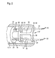
- FIG. 2 shows a partial view of the fuel injection valve according to the invention.
- FIG. 1 shows schematically a fuel injection valve according to the invention.
- the fuel injection valve is used for example in the so-called direct injection and serves to inject fuel, such as gasoline or diesel, in a combustion chamber of an internal combustion engine.
- the fuel injection valve has a valve housing 1 with an input channel 2 for the fuel.
- the valve housing 1 is, for example, cylindrical in shape with a housing cover 3 arranged on the front side.
- an actuator 4 for example a piezoelectric or magnetostrictive actuator, is arranged for the axial adjustment of a valve needle 5.
- the valve needle 5 is provided in the valve housing 1 axially movable with respect to a valve axis 8 and has, for example, a needle shaft 9 facing the actuator 4 and a valve closing body 10 facing away from the actuator 4.
- the valve closing body 10 cooperates with a valve seat 11.
- the piezoelectric actuator 4 consists of a plurality of piezoceramic layers, which perform an expansion in the axial direction with respect to the valve axis 8 by applying an electrical voltage. In this case, the so-called inverse piezoelectric effect is utilized in which electrical energy is converted into mechanical energy.
- the stroke of the piezoelectric actuator 4 generated by the application of the electric voltage is transmitted to the valve needle 5, which executes, for example, a stroke of 40 to 50 micrometers and opens the fuel injection valve in this way.
- the actuator 4 is shortened and the valve needle 5 is moved back by means of a return spring 12 in the direction of the valve seat 11 and closes the fuel injection valve.
- the piezoelectric actuator 4 is arranged to protect against tensile and bending stresses, for example in an actuator sleeve 15 between an actuator head 16 and an actuator base 17 and biased in the axial direction with respect to the valve axis 8 to pressure.
- the actuator sleeve 15 is designed for example as a so-called tubular spring, which has, for example, recesses 18 to increase the elasticity.
- the actuator sleeve 15 is made of metal, for example steel, manufactured.
- the actuator head 16 is arranged on an end, the valve needle 4 end facing away from the actuator sleeve 15 and the actuator sleeve 15 cohesively and / or non-positively connected, for example by welding.
- the actuator base 17 is arranged on an end face, the valve needle 4 facing the end of the actuator sleeve 15 and also cohesively and / or non-positively connected to the actuator sleeve 15, for example by welding.
- a hydraulic coupler 19 is provided which compensates for the differences in the different linear expansion.
- the hydraulic coupler 19 thus ensures that the fuel injection valve with the valve needle 5, regardless of the respective temperature of the fuel injection valve in each case performs the same stroke. There must be no lifting losses, in which the stroke of the actuator 4 is not completely transmitted to the valve needle 5 and thus the stroke of the valve needle 5 is smaller than the stroke of the actuator. 4
- the hydraulic coupler 19 is arranged, for example, between the housing cover 3 and the actuator head 16 of the actuator sleeve 15 and designed, for example, cylindrical.
- the hydraulic coupler 19, the actuator 4 with the actuator sleeve 15 and the valve needle 5 are, for example, arranged concentrically with respect to the valve axis 8.
- an actuator housing 22 is provided in the valve housing 1, for example, which hermetically encloses the actuator 4 and the hydraulic coupler 19 and seals them against the fuel.
- the actuator housing 22 is designed, for example cylindrical and divides the interior of the valve housing 1 in a fuel-laden and flow-connected to the input channel 2 pressure chamber 23 and the actuator 4 and the hydraulic coupler 19 having actuator chamber 24.
- the needle shaft 9 of the valve needle 5 extends in the actuator chamber 24 starting from the actuator base 17 in the direction away from the actuator 4 and extends through the actuator housing 22 through an opening 25 to in the pressure chamber 23.
- the opening 25 is sealed by means of an elastic seal 35 so that no fuel from the pressure chamber 23 enters the actuator chamber 24.
- the actuator 4 has at least two actuator connections 26 on the actuator head 16, which are electrically connected via electrical lines 29 to a plug connection 30 provided on the valve housing 1.
- the actuator 4 is connected via this plug connection 30 to an external voltage source 31.
- the plug connections 30 are arranged, for example, on the housing cover 3 and project through this into the actuator chamber 24 of the actuator housing 22.
- the electrical lines 29 extend from the actuator terminals 26, starting from the actuator housing 22 in the direction away from the actuator 4 to the contact with the projecting into the actuator chamber 24 male terminals 30th
- the electrical leads 29 are, for example, commercially available insulated cables.
- the electrical leads 29 are inventively fixed between the Aktoran somebodyn 26 and the male terminals 30 to at least two bearings 33 so that they occupy a defined position in the valve housing 1 and the actuator housing 22.
- At least one electrical line 29 between two bearing points 33 has a strain relief 36, so that the electrical lines 29 are not mechanically stressed by the high-frequency lifting movements of the actuator 4 or the compensation movements of the hydraulic coupler 19.
- the Aktaktont ist is improved in this way and has a longer life.
- the strain relief 36 according to the invention is formed such that the length of the electrical line 29 between the two bearings 33 is greater than the axial distance with respect to the valve axis 8 between the bearings 33. This results in a loop between the bearings 33, loop or bend the electrical line 29.
- the bearings 33 are inventively provided on a cable bearing 37, which is arranged in the actuator housing 22.
- the cable storage 37 is made elastic and made for example of plastic. According to the embodiment, the cable storage 37 is sleeve-shaped.
- the cable bearing 37 has two annular sections 38, which are spaced apart from one another in the axial direction and are connected to one another by at least one web 39 extending in the axial direction with respect to the valve axis 8.
- the ring portions 38 are arranged, for example, in the axial region of the hydraulic coupler 19 and surround this annular.
- the electrical leads 29 are fixed in the region of the bearing points 33 on the ring sections 38 by being injected into the ring sections 38 and penetrating them. However, the electrical leads 29 can also be fastened in a different manner to the ring sections 38, for example by gluing or welding.
- the cable storage 37 is produced for example by means of injection molding.
- the electrical lines 29 are inserted during injection molding, for example, in the injection mold and then encapsulated at the bearings 33 of plastic. In this way, the electrical leads 29 are fixedly connected to the cable storage 37 and integrated in this.
- the cable storage 37 can also be produced in other ways.
- the cable storage 37 rests with its circumference, for example, on the actuator housing 22 and is arranged in the axial direction, for example, between a stop 43 provided on the actuator housing 22 and the housing cover 3.
- the cable bearing 37 is mounted in this way in the axial and radial directions in the actuator housing 22.
- the electrical leads 29 of the cable bearing 37 are first connected to the connector terminals 30 and the Aktoran somebodyn 26 during assembly and then inserted as a composite together with the actuator 4 in the valve housing 1 and actuator housing 22.
- a high voltage of the voltage source 31 or no voltage is applied to the actuator 4.
- the high power switch 32 is connected to a positive pole of the power source 31.
- the voltage source 31 is, for example, a transformer which, for example, increases a 12V on-board voltage of a vehicle to a high voltage.
- FIG. 2 shows a partial view of the fuel injection valve according to the invention with the cable bearing.
- the radial thickness of the annular section 38 is increased, for example, only in the region of the bearing points 33 in order to firmly enclose the electrical leads 29.
- the ring portions 38 of the cable bearing 37 have thereby on its circumference in the region of the bearings 33 bulges 40. In this way, material is saved in the manufacture of the cable bearing 37.
Abstract
Description
Die Erfindung geht aus von einem Brennstoffeinspritzventil nach der Gattung des Hauptanspruchs.
Es ist schon ein Brennstoffeinspritzventil aus der
It is already a fuel injector from the
Das erfindungsgemäße Brennstoffeinspritzventil mit den kennzeichnenden Merkmalen des Hauptanspruchs hat demgegenüber den Vorteil, daß die Kontaktierung des Aktors auf einfache Art und Weise verbessert wird und die elektrischen Leitungen vor einer mechanischen Beschädigung geschützt werden, indem zumindest eine elektrische Leitung zwischen zwei Lagerstellen eine Zugentlastung aufweist. Außerdem wird die Aktorkontaktierung kostengünstiger gestaltet.The fuel injection valve according to the invention with the characterizing features of the main claim has the advantage that the contact of the actuator is improved in a simple manner and the electrical lines are protected against mechanical damage by at least one electrical line between two bearings has a strain relief. In addition, the Aktorkontaktierung is designed cheaper.
Durch die in den Unteransprüchen aufgeführten Maßnahmen sind vorteilhafte Weiterbildungen und Verbesserungen des im Hauptanspruch angegebenen Brennstoffeinspritzventils möglich.The measures listed in the dependent claims advantageous refinements and improvements of the main claim fuel injector are possible.
Die Zugentlastung ist vorteilhafterweise derart gebildet, dass die Länge der elektrischen Leitung zwischen den beiden Lagerstellen größer ist als der axiale Abstand bezüglich einer Ventilachse zwischen den Lagerstellen.The strain relief is advantageously formed such that the length of the electrical line between the two bearing points is greater than the axial distance with respect to a valve axis between the bearings.
Besonders vorteilhaft ist, wenn die Lagerstellen für die elektrischen Leitungen an einem in dem Ventilgehäuse angeordneten Kabellager ausgebildet sind, da auf diese Weise eine definierte Position der elektrischen Leitungen gewährleistet ist. Außerdem ermöglicht das Kabellager eine einfache Montage der elektrischen Leitungen am Brennstoffeinspritzventil.It is particularly advantageous if the bearing points for the electrical lines are formed on a cable housing arranged in the valve housing, since in this way a defined position of the electrical lines is ensured. In addition, the cable storage allows easy mounting of electrical lines on the fuel injector.
Gemäß einer vorteilhaften Ausführung ist das Kabellager hülsenförmig und elastisch ausgebildet.According to an advantageous embodiment, the cable bearing is sleeve-shaped and elastic.
Sehr vorteilhaft ist es, wenn das Kabellager durch zwei Ringabschnitte gebildet ist, die durch zumindest einen Steg miteinander verbunden sind, da auf diese Weise eine hohe axiale Elastizität des Kabellagers erreicht wird, so dass dieses die hochfrequenten Schwingungen des Aktors über die Lebensdauer des Brennstoffeinspritzventils ertragen kann.It is very advantageous if the cable bearing is formed by two ring sections, which are connected to each other by at least one web, since in this way a high axial elasticity of the cable bearing is achieved, so that this endure the high-frequency vibrations of the actuator over the life of the fuel injection valve can.
Auch vorteilhaft ist, wenn die elektrischen Leitungen die Ringabschnitte an den Lagerstellen durchdringen und auf diese Weise dort fixiert sind.It is also advantageous if the electrical lines penetrate the ring sections at the bearing points and are fixed in this way there.
Desweiteren vorteilhaft ist, wenn der Aktor ein Piezoaktor ist, der mit einem hydraulischen Koppler zusammenwirkt, wobei das Kabellager den hydraulischen Koppler ringförmig umgibt, da bei einem Piezoaktor die mechanische Belastung der elektrischen Leitungen besonders hoch ist. Beispielsweise weist das Brennstoffeinspritzventil eine mit einem Ventilsitz zusammenwirkende Ventilnadel auf, wobei der hydraulische Koppler zwischen dem Piezoaktor und einer der Ventilnadel abgewandten Stirnseite des Ventilgehäuses angeordnet ist.Furthermore, it is advantageous if the actuator is a piezoelectric actuator, which cooperates with a hydraulic coupler, wherein the cable storage ring surrounds the hydraulic coupler, as in a piezoelectric actuator, the mechanical load on the electrical lines is particularly high. For example, the fuel injection valve has a valve needle cooperating with a valve seat, the hydraulic coupler being arranged between the piezoactuator and an end face of the valve housing facing away from the valve needle.
Ein Ausführungsbeispiel der Erfindung ist in der Zeichnung vereinfacht dargestellt und in der nachfolgenden Beschreibung näher erläutert. Es zeigen Fig.1 im Schnitt eine Ansicht des erfindungsgemäßen Brennstoffeinspritzventils und Fig.2 eine Teilansicht des erfindungsgemäßen Brennstoffeinspritzventils.An embodiment of the invention is shown in simplified form in the drawing and explained in more detail in the following description. 1 shows in section a view of the fuel injection valve according to the invention and FIG. 2 shows a partial view of the fuel injection valve according to the invention.
Fig.1 zeigt schematisch ein erfindungsgemäßes Brennstoffeinspritzventil.1 shows schematically a fuel injection valve according to the invention.
Das Brennstoffeinspritzventil wird beispielsweise bei der sogenannten Direkteinspritzung verwendet und dient dazu, Kraftstoff, beispielsweise Benzin oder Diesel, in einen Brennraum einer Brennkraftmaschine einzuspritzen.The fuel injection valve is used for example in the so-called direct injection and serves to inject fuel, such as gasoline or diesel, in a combustion chamber of an internal combustion engine.
Das Brennstoffeinspritzventil hat ein Ventilgehäuse 1 mit einem Eingangskanal 2 für den Kraftstoff. Das Ventilgehäuse 1 ist beispielsweise zylinderförmig ausgebildet mit einem stirnseitig angeordneten Gehäusedeckel 3. In dem Ventilgehäuse 1 ist ein Aktor 4, beispielsweise ein piezoelektrischer oder magnetostriktiver Aktor, zur axialen Verstellung einer Ventilnadel 5 angeordnet. Die Ventilnadel 5 ist in dem Ventilgehäuse 1 axial beweglich bezüglich einer Ventilachse 8 vorgesehen und weist beispielsweise einen dem Aktor 4 zugewandten Nadelschaft 9 und einen dem Aktor 4 abgewandten Ventilschließkörper 10 auf. Der Ventilschließkörper 10 wirkt mit einem Ventilsitz 11 zusammen.The fuel injection valve has a valve housing 1 with an
Der piezoelektrische Aktor 4 besteht aus einer Vielzahl von piezokeramischen Schichten, die durch Anlegen einer elektrischen Spannung eine Dehnung in axialer Richtung bezüglich der Ventilachse 8 ausführen. Dabei wird der sogenannte inverse piezoelektrische Effekt ausgenutzt, bei dem elektrische Energie in mechanische Energie umgewandelt wird. Der durch das Anlegen der elektrischen Spannung erzeugte Hub des piezoelektrischen Aktors 4 wird auf die Ventilnadel 5 übertragen, die beispielsweise einen Hub von 40 bis 50 Mikrometer ausführt und das Brennstoffeinspritzventil auf diese Weise öffnet. Durch Abschalten der elektrischen Spannung verkürzt sich der Aktor 4 und die Ventilnadel 5 wird mittels einer Rückstellfeder 12 wieder in Richtung des Ventilsitzes 11 zurückbewegt und schließt das Brennstoffeinspritzventil.The
Der piezoelektrische Aktor 4 ist zum Schutz vor Zug- und Biegespannungen beispielsweise in einer Aktorhülse 15 zwischen einem Aktorkopf 16 und einem Aktorfuß 17 angeordnet und in axialer Richtung bezüglich der Ventilachse 8 auf Druck vorgespannt. Die Aktorhülse 15 ist beispielsweise als sogenannte Rohrfeder ausgeführt, die zur Erhöhung der Elastizität beispielsweise Ausnehmungen 18 aufweist. Die Aktorhülse 15 ist aus Metall, beispielsweise Stahl, hergestellt.Der Aktorkopf 16 ist an einem stirnseitigen, der Ventilnadel 4 abgewandten Ende der Aktorhülse 15 angeordnet und mit der Aktorhülse 15 stoffschlüssig und/oder kraftschlüssig verbunden, beispielsweise mittels Schweißen. Der Aktorfuß 17 ist an einem stirnseitigen, der Ventilnadel 4 zugewandten Ende der Aktorhülse 15 angeordnet und ebenfalls stoffschlüssig und/oder kraftschlüssig mit der Aktorhülse 15 verbunden, beispielsweise mittels Schweißen.The
Da sich der Aktor 4 und die übrigen Komponenten des Brennstoffeinspritzventils, beispielsweise das Ventilgehäuse 1, wegen unterschiedlicher thermischer Ausdehnungskoeffizienten bei Temperaturänderung unterschiedlich stark ausdehnen, ist ein hydraulischer Koppler 19 vorgesehen, der die Differenzen in der unterschiedlichen Längenausdehnung ausgleicht. Der hydraulische Koppler 19 stellt somit sicher, daß das Brennstoffeinspritzventil mit der Ventilnadel 5 unabhängig von der jeweiligen Temperatur des Brennstoffeinspritzventils jeweils den gleichen Hub ausführt. Es dürfen keine Hubverluste auftreten, bei denen der Hub des Aktors 4 nicht vollständig auf die Ventilnadel 5 übertragen wird und somit der Hub der Ventilnadel 5 kleiner ist als der Hub des Aktors 4.Since the
Der hydraulische Koppler 19 ist beispielsweise zwischen dem Gehäusedeckel 3 und dem Aktorkopf 16 der Aktorhülse 15 angeordnet und beispielsweise zylinderförmig ausgeführt.The
Bei zeitlich schnellen auf den hydraulischen Koppler 19 wirkenden Bewegungsvorgängen, wie beispielsweise der Ausdehung des Aktors 4 bei Beschalten mit einer elektrischen Spannung, verhält sich der hydraulische Koppler 19 als extrem steifes Bauteil. Bei zeitlich langsamen Bewegungsvorgängen, wie beispielsweise der Dehnung aufgrund von Temperaturänderungen, verändert er seine axiale Länge bezüglich der Ventilachse 8 und gleicht auf diese Weise Dehnungsdifferenzen aus.When temporally fast acting on the
Der hydraulische Koppler 19, der Aktor 4 mit der Aktorhülse 15 und die Ventilnadel 5 sind beispielsweise konzentrisch bezüglich der Ventilachse 8 angeordnet.The
Um den Aktor 4 und den hydraulischen Koppler 19 gegenüber dem Kraftstoff zu kapseln, ist im Ventilgehäuse 1 beispielsweise ein Aktorgehäuse 22 vorgesehen, das den Aktor 4 und den hydraulischen Koppler 19 hermetisch umschließt und gegenüber dem Kraftstoff abdichtet. Das Aktorgehäuse 22 ist beispielsweise zylinderförmig ausgeführt und teilt den Innenraum des Ventilgehäuses 1 in einen mit Kraftstoff beladenen und mit dem Eingangskanal 2 strömungsverbundenen Druckraum 23 und einen den Aktor 4 und den hydraulischen Koppler 19 aufweisenden Aktorraum 24. Der Nadelschaft 9 der Ventilnadel 5 verläuft im Aktorraum 24 vom Aktorfuß 17 ausgehend in vom Aktor 4 abgewandter Richtung und durchragt das Aktorgehäuse 22 durch eine Öffnung 25 bis in den Druckraum 23. Die Öffnung 25 ist mittels einer elastischen Dichtung 35 abgedichtet, so daß kein Kraftstoff aus dem Druckraum 23 in den Aktorraum 24 gelangt.In order to encapsulate the
Der Aktor 4 weist beispielsweise am Aktorkopf 16 zumindest zwei Aktoranschlüsse 26 auf, die über elektrische Leitungen 29 mit einem am Ventilgehäuse 1 vorgesehenen Steckeranschluss 30 elektrisch verbunden sind. Der Aktor 4 wird über diesen Steckeranschluss 30 an eine externe Spannungsquelle 31 angeschlossen. Die Steckeranschlüsse 30 sind beispielsweise an dem Gehäusedeckel 3 angeordnet und durchragen diesen bis in den Aktorraum 24 des Aktorgehäuses 22.
Die elektrischen Leitungen 29 verlaufen von den Aktoranschlüssen 26 ausgehend durch das Aktorgehäuse 22 in vom Aktor 4 abgewandter Richtung bis zur Kontaktierung mit den in den Aktorraum 24 hineinragenden Steckeranschlüssen 30.For example, the
The
Die elektrischen Leitungen 29 sind beispielsweise handelsübliche isolierte Kabel.The
Die elektrischen Leitungen 29 sind erfindungsgemäß zwischen den Aktoranschlüssen 26 und den Steckeranschlüssen 30 an zumindest zwei Lagerstellen 33 fixiert, damit diese im Ventilgehäuse 1 bzw. im Aktorgehäuse 22 eine definierte Position einnehmen.The
Erfindungsgemäß weist zumindest eine elektrische Leitung 29 zwischen zwei Lagerstellen 33 eine Zugentlastung 36 auf, so dass die elektrischen Leitungen 29 nicht durch die hochfrequenten Hubbewegungen des Aktors 4 oder die Ausgleichsbewegungen des hydraulischen Kopplers 19 mechanisch beansprucht werden. Die Aktorkontaktierung wird auf diese Weise verbessert und weist eine höhere Lebensdauer auf.According to the invention, at least one
Die Zugentlastung 36 ist erfindungsgemäß derart gebildet, dass die Länge der elektrischen Leitung 29 zwischen den beiden Lagerstellen 33 größer ist als der axiale Abstand bezüglich der Ventilachse 8 zwischen den Lagerstellen 33. Dadurch ergibt sich zwischen den Lagerstellen 33 eine Schlaufe, Schlinge bzw. Biegung der elektrischen Leitung 29.The
Die Lagerstellen 33 sind erfindungsgemäß an einem Kabellager 37 vorgesehen, das in dem Aktorgehäuse 22 angeordnet ist. Das Kabellager 37 ist elastisch ausgeführt und beispielsweise aus Kunststoff hergestellt. Gemäss dem Ausführungsbeispiel ist das Kabellager 37 hülsenförmig ausgebildet.The
Beispielsweise weist das Kabellager 37 zwei Ringabschnitte 38 auf, die in axialer Richtung zueinander beabstandet und durch zumindest einen in axialer Richtung bezüglich der Ventilachse 8 verlaufenden Steg 39 miteinander verbunden sind. Die Ringabschnitte 38 sind beispielsweise im axialen Bereich des hydraulischen Kopplers 19 angeordnet und umgeben diesen ringförmig. Die elektrischen Leitungen 29 sind im Bereich der Lagerstellen 33 an den Ringabschnitten 38 fixiert, indem sie in die Ringabschnitte 38 eingespritzt sind und diese durchdringen. Die elektrischen Leitungen 29 können aber auch auf andere Art und Weise an den Ringabschnitten 38 befestigt sein, beispielsweise durch Kleben oder Schweissen.For example, the cable bearing 37 has two
Das Kabellager 37 wird beispielsweise mittels Spritzguß hergestellt. Die elektrischen Leitungen 29 werden beim Spritzgießen beispielsweise mit in das Spritzwerkzeug eingelegt und anschließend an den Lagerstellen 33 von Kunststoff umspritzt. Auf diese Weise sind die elektrischen Leitungen 29 fest mit dem Kabellager 37 verbunden und in diesem integriert. Das Kabellager 37 kann aber selbstverständlich auch auf andere Weise hergestellt werden.The
Das Kabellager 37 liegt mit seinem Umfang beispielsweise an dem Aktorgehäuse 22 an und ist in axialer Richtung beispielsweise zwischen einem am Aktorgehäuse 22 vorgesehenen Anschlag 43 und dem Gehäusedeckel 3 angeordnet. Das Kabellager 37 ist auf diese Weise in axialer und radialer Richtung in dem Aktorgehäuse 22 gelagert.The
Die elektrischen Leitungen 29 des Kabellagers 37 werden bei der Montage zunächst mit den Steckeranschlüssen 30 und den Aktoranschlüssen 26 verbunden und anschließend als Verbund zusammen mit dem Aktor 4 in das Ventilgehäuse 1 bzw. Aktorgehäuse 22 eingeschoben.The electrical leads 29 of the
Am Aktor 4 liegt abhängig von der Stellung eines Hochleistungsschalters 32 entweder eine Hochspannung der Spannungsquelle 31 oder keine Spannung an. Der Hochleistungsschalter 32 ist mit einem Pluspol der Spannungsquelle 31 verbunden. Die Spannungsquelle 31 ist beispielsweise ein Transformator, der beispielsweise eine 12V-Bordspannung eines Fahrzeugs auf eine Hochspannung erhöht.Depending on the position of a high-
In Fig.2 ist eine Teilansicht des erfindungsgemäßen Brennstoffeinspritzventils mit dem Kabellager gezeigt.FIG. 2 shows a partial view of the fuel injection valve according to the invention with the cable bearing.
Bei dem Brennstoffeinspritzventil nach Fig.2 sind die gegenüber dem Brennstoffeinspritzventil nach Fig. gleichbleibenden oder gleichwirkenden Teile durch die gleichen Bezugszeichen gekennzeichnet.In the fuel injection valve according to Figure 2, the opposite to the fuel injection valve according to FIG. Constant or equivalent parts are identified by the same reference numerals.
Die radiale Dicke des Ringabschnitts 38 ist beispielsweise jeweils nur im Bereich der Lagerstellen 33 erhöht, um die elektrischen Leitungen 29 fest einzuschliessen. Die Ringabschnitte 38 des Kabellagers 37 haben dadurch an ihrem Umfang im Bereich der Lagerstellen 33 Ausbuchtungen 40. Auf diese Weise wird Material bei der Herstellung des Kabellagers 37 eingespart.The radial thickness of the
Claims (10)
Applications Claiming Priority (1)
| Application Number | Priority Date | Filing Date | Title |
|---|---|---|---|
| DE102005016461A DE102005016461A1 (en) | 2005-04-11 | 2005-04-11 | Fuel injection valve for internal combustion engine, has actuator electrically contacted by electrical conductors that are fixed at bearing points, where one electrical conductor provided between bearing points has cable cleat |
Publications (3)
| Publication Number | Publication Date |
|---|---|
| EP1712774A2 true EP1712774A2 (en) | 2006-10-18 |
| EP1712774A3 EP1712774A3 (en) | 2007-05-02 |
| EP1712774B1 EP1712774B1 (en) | 2009-11-25 |
Family
ID=36693959
Family Applications (1)
| Application Number | Title | Priority Date | Filing Date |
|---|---|---|---|
| EP06111237A Expired - Fee Related EP1712774B1 (en) | 2005-04-11 | 2006-03-16 | Fuel injector |
Country Status (2)
| Country | Link |
|---|---|
| EP (1) | EP1712774B1 (en) |
| DE (2) | DE102005016461A1 (en) |
Cited By (3)
| Publication number | Priority date | Publication date | Assignee | Title |
|---|---|---|---|---|
| EP1961951A1 (en) * | 2007-02-22 | 2008-08-27 | Siemens Aktiengesellschaft | Electrical connector and method for coupling an electrical connector to an actuator unit |
| WO2013026614A1 (en) * | 2011-08-22 | 2013-02-28 | Robert Bosch Gmbh | Valve for measuring out a flowing medium |
| WO2015058998A1 (en) * | 2013-10-23 | 2015-04-30 | Continental Automotive Gmbh | Injector and contact element for the same |
Families Citing this family (1)
| Publication number | Priority date | Publication date | Assignee | Title |
|---|---|---|---|---|
| DE102015219568B4 (en) * | 2015-10-09 | 2017-06-08 | Continental Automotive Gmbh | Actuator with valve unit for piezoservo driven injector |
Citations (1)
| Publication number | Priority date | Publication date | Assignee | Title |
|---|---|---|---|---|
| US5168189A (en) | 1991-09-18 | 1992-12-01 | Caterpillar Inc. | Solderless connector for a solid state motor stack |
Family Cites Families (5)
| Publication number | Priority date | Publication date | Assignee | Title |
|---|---|---|---|---|
| JPS62157274A (en) * | 1985-12-28 | 1987-07-13 | Aisan Ind Co Ltd | Fuel injection valve |
| GB9919661D0 (en) * | 1999-08-20 | 1999-10-20 | Lucas Industries Ltd | Actuator housing |
| US6279842B1 (en) * | 2000-02-29 | 2001-08-28 | Rodi Power Systems, Inc. | Magnetostrictively actuated fuel injector |
| DE10205909B4 (en) * | 2002-02-13 | 2005-11-10 | Siemens Ag | Sealing element for the piezoelectric actuator of a fuel injection valve |
| EP1445471B1 (en) * | 2003-01-24 | 2006-05-17 | Siemens VDO Automotive S.p.A. | Terminal adapter and metering device comprising same |
-
2005
- 2005-04-11 DE DE102005016461A patent/DE102005016461A1/en not_active Withdrawn
-
2006
- 2006-03-16 DE DE502006005436T patent/DE502006005436D1/en active Active
- 2006-03-16 EP EP06111237A patent/EP1712774B1/en not_active Expired - Fee Related
Patent Citations (1)
| Publication number | Priority date | Publication date | Assignee | Title |
|---|---|---|---|---|
| US5168189A (en) | 1991-09-18 | 1992-12-01 | Caterpillar Inc. | Solderless connector for a solid state motor stack |
Cited By (9)
| Publication number | Priority date | Publication date | Assignee | Title |
|---|---|---|---|---|
| EP1961951A1 (en) * | 2007-02-22 | 2008-08-27 | Siemens Aktiengesellschaft | Electrical connector and method for coupling an electrical connector to an actuator unit |
| WO2013026614A1 (en) * | 2011-08-22 | 2013-02-28 | Robert Bosch Gmbh | Valve for measuring out a flowing medium |
| US20140312252A1 (en) * | 2011-08-22 | 2014-10-23 | Dietmar Schmieder | Valve for Metering a Fluid Medium |
| JP2014529032A (en) * | 2011-08-22 | 2014-10-30 | ローベルト ボツシユ ゲゼルシヤフト ミツト ベシユレンクテル ハフツングRobert Bosch Gmbh | Valve for metering a flowing medium |
| US9567957B2 (en) | 2011-08-22 | 2017-02-14 | Robert Bosch Gmbh | Electrical leads for a valve |
| WO2015058998A1 (en) * | 2013-10-23 | 2015-04-30 | Continental Automotive Gmbh | Injector and contact element for the same |
| CN105637210A (en) * | 2013-10-23 | 2016-06-01 | 大陆汽车有限公司 | Injector and contact element for the same |
| CN105637210B (en) * | 2013-10-23 | 2018-08-17 | 大陆汽车有限公司 | Injector and contact element for it |
| US10215142B2 (en) | 2013-10-23 | 2019-02-26 | Continental Automotive Gmbh | Injector and contact element for the same |
Also Published As
| Publication number | Publication date |
|---|---|
| DE102005016461A1 (en) | 2006-10-12 |
| EP1712774B1 (en) | 2009-11-25 |
| DE502006005436D1 (en) | 2010-01-07 |
| EP1712774A3 (en) | 2007-05-02 |
Similar Documents
| Publication | Publication Date | Title |
|---|---|---|
| EP1593837B1 (en) | Fuel injection valve | |
| EP1906464B1 (en) | Piezo actuator with a jacket for placing in a piezo injector | |
| EP1901360B1 (en) | Piezo actuator module with a cladded piezo actuator | |
| EP1712774B1 (en) | Fuel injector | |
| EP1714024B1 (en) | Fuel system part with a cable leadthrough | |
| EP1741922A1 (en) | Fuel injector | |
| EP3109911B1 (en) | Piezo actuator module, method for producing a piezo actuator module and piezo injector | |
| DE10317148B4 (en) | Fuel injector | |
| EP3060790B1 (en) | Injector | |
| DE102005029100B4 (en) | Fuel injector | |
| DE10046661A1 (en) | Piezoactuator e.g. for fuel injector of IC engine, has piezoelement clamped between head and foot parts, and casing attached securely to foot part in sealed manner | |
| WO2007023047A1 (en) | Arrangement with a piezo actuator | |
| EP1820960B1 (en) | Fuel injector | |
| WO2016045831A1 (en) | Actuator module with a stack of piezoceramics | |
| DE102017204692A1 (en) | fuel injector | |
| EP2013923B1 (en) | Piezoactuator with a casing | |
| DE102006059694A1 (en) | Actuator module for use in piezoactuator, has piezoelement arranged between actuator head and actuator foot and piezoelement encloses fluid-filled casing of piezoactuator | |
| DE102009027101A1 (en) | Flexible casing for piezoelectric actuator for fuel injection system of air compression, self ignition internal combustion engine, has internal recesses, where is positioned partially against outer surface of actuator in expanded condition | |
| EP1528607B1 (en) | Actuator module | |
| EP1973176A2 (en) | Method and device for manufacturing a piezo-electric actuator module with an encased piezo actuator and a piezo actuator module | |
| EP1912265B1 (en) | Actuator module with a cladded piezo actuator | |
| DE102009002876A1 (en) | Piezoelectric actuator and manufacturing method therefor | |
| EP2649295B1 (en) | Piezoelectric actuator module and fuel injection valve | |
| DE102008044164A1 (en) | Actuator module for fuel injection valve, particularly injector for fuel injection system, has actuator, where adapter is fixed to actuator, and centering element has bolt-shaped centering extension | |
| DE102007042402A1 (en) | Piezoactuator module with a protective layer system and a method for its production |
Legal Events
| Date | Code | Title | Description |
|---|---|---|---|
| PUAI | Public reference made under article 153(3) epc to a published international application that has entered the european phase |
Free format text: ORIGINAL CODE: 0009012 |
|
| AK | Designated contracting states |
Kind code of ref document: A2 Designated state(s): AT BE BG CH CY CZ DE DK EE ES FI FR GB GR HU IE IS IT LI LT LU LV MC NL PL PT RO SE SI SK TR |
|
| AX | Request for extension of the european patent |
Extension state: AL BA HR MK YU |
|
| PUAL | Search report despatched |
Free format text: ORIGINAL CODE: 0009013 |
|
| AK | Designated contracting states |
Kind code of ref document: A3 Designated state(s): AT BE BG CH CY CZ DE DK EE ES FI FR GB GR HU IE IS IT LI LT LU LV MC NL PL PT RO SE SI SK TR |
|
| AX | Request for extension of the european patent |
Extension state: AL BA HR MK YU |
|
| RIC1 | Information provided on ipc code assigned before grant |
Ipc: H01R 13/58 20060101ALI20070326BHEP Ipc: F02M 51/00 20060101ALI20070326BHEP Ipc: F02M 51/06 20060101AFI20060802BHEP |
|
| 17P | Request for examination filed |
Effective date: 20071102 |
|
| 17Q | First examination report despatched |
Effective date: 20071130 |
|
| AKX | Designation fees paid |
Designated state(s): DE FR GB IT |
|
| GRAP | Despatch of communication of intention to grant a patent |
Free format text: ORIGINAL CODE: EPIDOSNIGR1 |
|
| GRAS | Grant fee paid |
Free format text: ORIGINAL CODE: EPIDOSNIGR3 |
|
| GRAA | (expected) grant |
Free format text: ORIGINAL CODE: 0009210 |
|
| AK | Designated contracting states |
Kind code of ref document: B1 Designated state(s): DE FR GB IT |
|
| REG | Reference to a national code |
Ref country code: GB Ref legal event code: FG4D Free format text: NOT ENGLISH |
|
| REF | Corresponds to: |
Ref document number: 502006005436 Country of ref document: DE Date of ref document: 20100107 Kind code of ref document: P |
|
| PLBE | No opposition filed within time limit |
Free format text: ORIGINAL CODE: 0009261 |
|
| STAA | Information on the status of an ep patent application or granted ep patent |
Free format text: STATUS: NO OPPOSITION FILED WITHIN TIME LIMIT |
|
| 26N | No opposition filed |
Effective date: 20100826 |
|
| REG | Reference to a national code |
Ref country code: FR Ref legal event code: PLFP Year of fee payment: 11 |
|
| REG | Reference to a national code |
Ref country code: FR Ref legal event code: PLFP Year of fee payment: 12 |
|
| PGFP | Annual fee paid to national office [announced via postgrant information from national office to epo] |
Ref country code: FR Payment date: 20170323 Year of fee payment: 12 |
|
| PGFP | Annual fee paid to national office [announced via postgrant information from national office to epo] |
Ref country code: GB Payment date: 20170327 Year of fee payment: 12 |
|
| PGFP | Annual fee paid to national office [announced via postgrant information from national office to epo] |
Ref country code: IT Payment date: 20170323 Year of fee payment: 12 |
|
| GBPC | Gb: european patent ceased through non-payment of renewal fee |
Effective date: 20180316 |
|
| PG25 | Lapsed in a contracting state [announced via postgrant information from national office to epo] |
Ref country code: IT Free format text: LAPSE BECAUSE OF NON-PAYMENT OF DUE FEES Effective date: 20180316 Ref country code: GB Free format text: LAPSE BECAUSE OF NON-PAYMENT OF DUE FEES Effective date: 20180316 |
|
| PG25 | Lapsed in a contracting state [announced via postgrant information from national office to epo] |
Ref country code: FR Free format text: LAPSE BECAUSE OF NON-PAYMENT OF DUE FEES Effective date: 20180331 |
|
| PGFP | Annual fee paid to national office [announced via postgrant information from national office to epo] |
Ref country code: DE Payment date: 20190520 Year of fee payment: 14 |
|
| REG | Reference to a national code |
Ref country code: DE Ref legal event code: R119 Ref document number: 502006005436 Country of ref document: DE |
|
| PG25 | Lapsed in a contracting state [announced via postgrant information from national office to epo] |
Ref country code: DE Free format text: LAPSE BECAUSE OF NON-PAYMENT OF DUE FEES Effective date: 20201001 |