EP1711972B1 - Elektrochemischer thermo-dynamo - Google Patents
Elektrochemischer thermo-dynamo Download PDFInfo
- Publication number
- EP1711972B1 EP1711972B1 EP04741868A EP04741868A EP1711972B1 EP 1711972 B1 EP1711972 B1 EP 1711972B1 EP 04741868 A EP04741868 A EP 04741868A EP 04741868 A EP04741868 A EP 04741868A EP 1711972 B1 EP1711972 B1 EP 1711972B1
- Authority
- EP
- European Patent Office
- Prior art keywords
- electrolyte
- electrochemical
- porous electrodes
- cell
- pressure
- Prior art date
- Legal status (The legal status is an assumption and is not a legal conclusion. Google has not performed a legal analysis and makes no representation as to the accuracy of the status listed.)
- Expired - Lifetime
Links
- 239000003792 electrolyte Substances 0.000 claims abstract description 59
- 230000003197 catalytic effect Effects 0.000 claims abstract description 21
- 230000002209 hydrophobic effect Effects 0.000 claims abstract description 12
- 230000001360 synchronised effect Effects 0.000 claims abstract description 3
- 239000000446 fuel Substances 0.000 claims description 32
- 238000000034 method Methods 0.000 claims description 18
- 230000008569 process Effects 0.000 claims description 18
- 230000015572 biosynthetic process Effects 0.000 claims description 9
- 239000007864 aqueous solution Substances 0.000 claims description 6
- 239000001257 hydrogen Substances 0.000 description 30
- 229910052739 hydrogen Inorganic materials 0.000 description 30
- UFHFLCQGNIYNRP-UHFFFAOYSA-N Hydrogen Chemical compound [H][H] UFHFLCQGNIYNRP-UHFFFAOYSA-N 0.000 description 27
- 238000005868 electrolysis reaction Methods 0.000 description 23
- 238000006243 chemical reaction Methods 0.000 description 21
- 239000007789 gas Substances 0.000 description 16
- 238000004519 manufacturing process Methods 0.000 description 15
- XLYOFNOQVPJJNP-UHFFFAOYSA-N water Substances O XLYOFNOQVPJJNP-UHFFFAOYSA-N 0.000 description 13
- 239000000126 substance Substances 0.000 description 11
- 229910052799 carbon Inorganic materials 0.000 description 9
- OKTJSMMVPCPJKN-UHFFFAOYSA-N Carbon Chemical compound [C] OKTJSMMVPCPJKN-UHFFFAOYSA-N 0.000 description 7
- 230000005611 electricity Effects 0.000 description 6
- 238000005516 engineering process Methods 0.000 description 6
- KWYUFKZDYYNOTN-UHFFFAOYSA-M Potassium hydroxide Chemical compound [OH-].[K+] KWYUFKZDYYNOTN-UHFFFAOYSA-M 0.000 description 5
- QVGXLLKOCUKJST-UHFFFAOYSA-N atomic oxygen Chemical compound [O] QVGXLLKOCUKJST-UHFFFAOYSA-N 0.000 description 5
- 230000007423 decrease Effects 0.000 description 5
- 229910052751 metal Inorganic materials 0.000 description 5
- 239000002184 metal Substances 0.000 description 5
- 239000001301 oxygen Substances 0.000 description 5
- 229910052760 oxygen Inorganic materials 0.000 description 5
- 230000003068 static effect Effects 0.000 description 5
- 239000002803 fossil fuel Substances 0.000 description 4
- 230000006872 improvement Effects 0.000 description 4
- 238000003786 synthesis reaction Methods 0.000 description 4
- 230000009466 transformation Effects 0.000 description 4
- 239000011230 binding agent Substances 0.000 description 3
- 239000006227 byproduct Substances 0.000 description 3
- 239000007788 liquid Substances 0.000 description 3
- 239000000843 powder Substances 0.000 description 3
- CURLTUGMZLYLDI-UHFFFAOYSA-N Carbon dioxide Chemical compound O=C=O CURLTUGMZLYLDI-UHFFFAOYSA-N 0.000 description 2
- 230000004913 activation Effects 0.000 description 2
- 150000001875 compounds Chemical class 0.000 description 2
- 238000010586 diagram Methods 0.000 description 2
- 238000003487 electrochemical reaction Methods 0.000 description 2
- 150000002431 hydrogen Chemical class 0.000 description 2
- 230000007062 hydrolysis Effects 0.000 description 2
- 238000006460 hydrolysis reaction Methods 0.000 description 2
- 239000000463 material Substances 0.000 description 2
- 239000012528 membrane Substances 0.000 description 2
- 150000002739 metals Chemical class 0.000 description 2
- 239000011148 porous material Substances 0.000 description 2
- 238000002407 reforming Methods 0.000 description 2
- 241000233866 Fungi Species 0.000 description 1
- 230000009471 action Effects 0.000 description 1
- 239000001569 carbon dioxide Substances 0.000 description 1
- 229910002092 carbon dioxide Inorganic materials 0.000 description 1
- 230000015556 catabolic process Effects 0.000 description 1
- 238000006555 catalytic reaction Methods 0.000 description 1
- 239000002800 charge carrier Substances 0.000 description 1
- 239000007795 chemical reaction product Substances 0.000 description 1
- 239000003245 coal Substances 0.000 description 1
- 230000002301 combined effect Effects 0.000 description 1
- 230000002860 competitive effect Effects 0.000 description 1
- 239000012141 concentrate Substances 0.000 description 1
- 239000004020 conductor Substances 0.000 description 1
- 239000000470 constituent Substances 0.000 description 1
- 238000006731 degradation reaction Methods 0.000 description 1
- 230000001419 dependent effect Effects 0.000 description 1
- 238000009792 diffusion process Methods 0.000 description 1
- 230000009977 dual effect Effects 0.000 description 1
- 230000005518 electrochemistry Effects 0.000 description 1
- 238000005265 energy consumption Methods 0.000 description 1
- 230000007613 environmental effect Effects 0.000 description 1
- 239000003344 environmental pollutant Substances 0.000 description 1
- 230000001747 exhibiting effect Effects 0.000 description 1
- XLYOFNOQVPJJNP-UHFFFAOYSA-M hydroxide Chemical compound [OH-] XLYOFNOQVPJJNP-UHFFFAOYSA-M 0.000 description 1
- -1 hydroxyl ions Chemical class 0.000 description 1
- 239000011159 matrix material Substances 0.000 description 1
- VNWKTOKETHGBQD-UHFFFAOYSA-N methane Chemical compound C VNWKTOKETHGBQD-UHFFFAOYSA-N 0.000 description 1
- 230000005012 migration Effects 0.000 description 1
- 238000013508 migration Methods 0.000 description 1
- 239000000203 mixture Substances 0.000 description 1
- 239000003345 natural gas Substances 0.000 description 1
- 229910000510 noble metal Inorganic materials 0.000 description 1
- 230000010287 polarization Effects 0.000 description 1
- 231100000719 pollutant Toxicity 0.000 description 1
- 238000010248 power generation Methods 0.000 description 1
- 230000005855 radiation Effects 0.000 description 1
- 239000000376 reactant Substances 0.000 description 1
- 230000035484 reaction time Effects 0.000 description 1
- 230000000717 retained effect Effects 0.000 description 1
- 230000002441 reversible effect Effects 0.000 description 1
- 239000004065 semiconductor Substances 0.000 description 1
- 238000000926 separation method Methods 0.000 description 1
- 239000007787 solid Substances 0.000 description 1
- 239000002918 waste heat Substances 0.000 description 1
- 239000002699 waste material Substances 0.000 description 1
Images
Classifications
-
- H—ELECTRICITY
- H01—ELECTRIC ELEMENTS
- H01M—PROCESSES OR MEANS, e.g. BATTERIES, FOR THE DIRECT CONVERSION OF CHEMICAL ENERGY INTO ELECTRICAL ENERGY
- H01M4/00—Electrodes
- H01M4/86—Inert electrodes with catalytic activity, e.g. for fuel cells
- H01M4/8605—Porous electrodes
-
- C—CHEMISTRY; METALLURGY
- C25—ELECTROLYTIC OR ELECTROPHORETIC PROCESSES; APPARATUS THEREFOR
- C25B—ELECTROLYTIC OR ELECTROPHORETIC PROCESSES FOR THE PRODUCTION OF COMPOUNDS OR NON-METALS; APPARATUS THEREFOR
- C25B1/00—Electrolytic production of inorganic compounds or non-metals
- C25B1/01—Products
- C25B1/02—Hydrogen or oxygen
- C25B1/04—Hydrogen or oxygen by electrolysis of water
-
- C—CHEMISTRY; METALLURGY
- C25—ELECTROLYTIC OR ELECTROPHORETIC PROCESSES; APPARATUS THEREFOR
- C25B—ELECTROLYTIC OR ELECTROPHORETIC PROCESSES FOR THE PRODUCTION OF COMPOUNDS OR NON-METALS; APPARATUS THEREFOR
- C25B15/00—Operating or servicing cells
-
- C—CHEMISTRY; METALLURGY
- C25—ELECTROLYTIC OR ELECTROPHORETIC PROCESSES; APPARATUS THEREFOR
- C25B—ELECTROLYTIC OR ELECTROPHORETIC PROCESSES FOR THE PRODUCTION OF COMPOUNDS OR NON-METALS; APPARATUS THEREFOR
- C25B9/00—Cells or assemblies of cells; Constructional parts of cells; Assemblies of constructional parts, e.g. electrode-diaphragm assemblies; Process-related cell features
- C25B9/05—Pressure cells
-
- H—ELECTRICITY
- H01—ELECTRIC ELEMENTS
- H01M—PROCESSES OR MEANS, e.g. BATTERIES, FOR THE DIRECT CONVERSION OF CHEMICAL ENERGY INTO ELECTRICAL ENERGY
- H01M8/00—Fuel cells; Manufacture thereof
- H01M8/04—Auxiliary arrangements, e.g. for control of pressure or for circulation of fluids
- H01M8/04007—Auxiliary arrangements, e.g. for control of pressure or for circulation of fluids related to heat exchange
-
- H—ELECTRICITY
- H01—ELECTRIC ELEMENTS
- H01M—PROCESSES OR MEANS, e.g. BATTERIES, FOR THE DIRECT CONVERSION OF CHEMICAL ENERGY INTO ELECTRICAL ENERGY
- H01M8/00—Fuel cells; Manufacture thereof
- H01M8/18—Regenerative fuel cells, e.g. redox flow batteries or secondary fuel cells
- H01M8/184—Regeneration by electrochemical means
- H01M8/186—Regeneration by electrochemical means by electrolytic decomposition of the electrolytic solution or the formed water product
-
- H—ELECTRICITY
- H01—ELECTRIC ELEMENTS
- H01M—PROCESSES OR MEANS, e.g. BATTERIES, FOR THE DIRECT CONVERSION OF CHEMICAL ENERGY INTO ELECTRICAL ENERGY
- H01M8/00—Fuel cells; Manufacture thereof
- H01M8/08—Fuel cells with aqueous electrolytes
- H01M8/083—Alkaline fuel cells
-
- Y—GENERAL TAGGING OF NEW TECHNOLOGICAL DEVELOPMENTS; GENERAL TAGGING OF CROSS-SECTIONAL TECHNOLOGIES SPANNING OVER SEVERAL SECTIONS OF THE IPC; TECHNICAL SUBJECTS COVERED BY FORMER USPC CROSS-REFERENCE ART COLLECTIONS [XRACs] AND DIGESTS
- Y02—TECHNOLOGIES OR APPLICATIONS FOR MITIGATION OR ADAPTATION AGAINST CLIMATE CHANGE
- Y02E—REDUCTION OF GREENHOUSE GAS [GHG] EMISSIONS, RELATED TO ENERGY GENERATION, TRANSMISSION OR DISTRIBUTION
- Y02E60/00—Enabling technologies; Technologies with a potential or indirect contribution to GHG emissions mitigation
- Y02E60/30—Hydrogen technology
- Y02E60/36—Hydrogen production from non-carbon containing sources, e.g. by water electrolysis
-
- Y—GENERAL TAGGING OF NEW TECHNOLOGICAL DEVELOPMENTS; GENERAL TAGGING OF CROSS-SECTIONAL TECHNOLOGIES SPANNING OVER SEVERAL SECTIONS OF THE IPC; TECHNICAL SUBJECTS COVERED BY FORMER USPC CROSS-REFERENCE ART COLLECTIONS [XRACs] AND DIGESTS
- Y02—TECHNOLOGIES OR APPLICATIONS FOR MITIGATION OR ADAPTATION AGAINST CLIMATE CHANGE
- Y02E—REDUCTION OF GREENHOUSE GAS [GHG] EMISSIONS, RELATED TO ENERGY GENERATION, TRANSMISSION OR DISTRIBUTION
- Y02E60/00—Enabling technologies; Technologies with a potential or indirect contribution to GHG emissions mitigation
- Y02E60/30—Hydrogen technology
- Y02E60/50—Fuel cells
Definitions
- the present invention generally relates to the field of the electrochemical cell. More particularly, the present invention relates to an electrochemical cell for water electrolysis and/or for the production of electricity using traditional technologies: the improvement increases the energetic yields.
- the electrolytic produced hydrogen has a high purity, but a high cost due both to the high cost of electric energy and to the low yield, i.e. low efficiency in the energy conversion from electric energy to the chemical energy.
- the energy sources of the first two systems are normally close enough to the site of further use of the electric energy whereas efficiency and quantity of electricity produced using the photovoltaic systems is higher in secluded parts of the hemisphere such as tropical and desert areas.
- the photovoltaic system concentrates the solar energy and can attain up to 30% of electric conversion efficiency through the use of a dual converter, two semiconductors with different band-gaps, receiving different fraction of radiation.
- the produced photovoltaic electric energy can conveniently be used for the production of high purity hydrogen and oxygen by water electrolysis.
- the H 2 stored as a metal hybrid is conveniently transported to the site of use and production of electric energy.
- a major goal in electro-conversion of solar energy is the use of electricity to produce H 2 and O 2 of high purity using water electrolysis, transporting the produced H 2 and O 2 to the utilization site and recombining them in a fuel cell for the production of electric energy.
- Alkaline electrolyser and alkaline cell based upon the technology of the alkaline fuel cells (AFC) were the most promising. These cells have been successfully used in the Apollo project and have the highest output voltage among fuel cells; furthermore, they may be operated over wide ranges of pressure and temperature.
- the technology behind the electrodes has been refined in the 1980's and uses low cost materials, C and Ni-mesh.
- the AFC needs pure gases in input which limited their application and the further development of this technology.
- the AFC are competitive with polymeric electrolyte fuel cells (PEFC).
- PEFC polymeric electrolyte fuel cells
- the alkaline fuel cells advantageously use low cost, carbon/nickel-mesh porous electrodes which can effectively be employed in a modified cell working as electrolyser.
- the alkaline fuel cells are easily polluted from the carbon dioxide contained in the hydrogen produced from the hydro-reforming of the fossil fuels. Such a problem does not exist when the hydrogen is produced from the water hydrolysis.
- the hydrogen can be then used in a fuel cell producing electric energy and closing the energy cycle of transformation of energy from electric energy into chemical energy and from chemical energy to electric energy with a total energy yield above the 50%.
- Document FR-A-1 452 701 discloses an electrochemical fuel cells module made up of couples of porous electrodes forming the anodes and the cathodes and delimitating external gaseous areas and internal areas containing the electrolyte and connected by an external electric circuit, a pressure modulator generating in use a pressure cycle acting at the outlet of the electrolyte.
- the alkaline fuel cells are the type of fuel cells with higher yield, up to 65%, and able to work from room temperature up to 200°C and at pressure up to 200 bar; this high flexibility allows the choice of the most suitable operative conditions either for optimize the total yields or for reduce the complexity and cost of the plants.
- Scope of the present invention is the improvement of the yield of an electrochemical cell with porous electrodes able to be used either as electrolyser or as fuel cell.
- electrochemical cells modules made up of couples of catalytic multilayer porous electrodes forming the anodes and the cathodes and delimitating external gaseous areas and internal areas containing the electrolyte and connected by an external electric circuit.
- the cell module comprises pressure modulators generating in use two pressure cycles independently synchronized but of opposite phase acting at the inlet and at the outlet of the circulating electrolyte, multilayer porous electrodes weeping on the gas side, and means for exchanging heat in the porous electrodes of the cell modules through the electrolyte flowing into the electrochemical cell.
- the multilayer porous electrodes are of the conductive and hydrophobic type on the gas side, the conductive and catalytic middle layers are hydrophobic and hydrophilic, and a hydrophilic layer, non-conductive and non-catalytic, is on the electrolyte side.
- the present invention provides an electrochemical process utilizing the claimed electrochemical cells according to which the pressure on the gas side is maintained a a pressure P up to 200 bar; the electrolyte pressure is varied stepwise between P+dP and P+dp by generating on the electrolyte positive pressure waves of amplitude dP and dp at the frequency f., heat is exchanged in the porous electrodes of the cell modules through the electrolyte flowing into the electrochemical cell.
- Alkaline fuel cells use an electrolyte that is an aqueous solution of potassium hydroxide (KOH) retained in porous electrodes.
- KOH potassium hydroxide
- concentration of KOH can be varied with the fuel cell operating temperature, which ranges from 65°C to 220°C.
- the charge carrier for an AFC is the hydroxyl ion (OH-) that migrates from the cathode to the anode where they react with hydrogen to produce water and electrons. Water formed at the anode migrates back to the cathode to regenerate hydroxyl ions.
- OH- hydroxyl ion
- ETC Electrochemical Thermodynamo
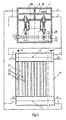
- FIG. 1 shows an Electrochemical Thermodynamo according to the invention.
- a battery of modules of bipolar cells 11 is represented.
- Each module is formed of a couple of porous electrodes (15) defining three zones, one filled with electrolyte (14) and the other two (16) external to the electrodes filled with gas at the same pressure P.
- On the frame of the battery anodic and cathodic gas adduction ducts (19, 20) are depicted.
- the porous electrodes (15) are of the weeping type and the drops are drawn from the ducts (17, 18) and recycled back to the electrolyte circuit.
- Two ducts (2, 3) in connection with the electrolyte inlet and outlet are shaped on the frame.
- Numeral (21) refers to the electrical connection to the electric circuit.
- valves pressure modulators are schematically represented on the top of the figure.
- the modulators are moved by a not drawn external motor for the circulation of the electrolyte into the electrochemical cells modules through the feeding pipes (1 and 2), the draining pipes (3 and 4).
- the rotating shaft (9) moves the cams(10) which work through the followers (0) of the tappet rods on the fungus heads of the valves (7) with return springs so that when a valve is open the other is closed and vice versa.
- Numerals (1) and (4) indicate respectively the electrolyte inlet and outlet, connected to two tanks at pressure P + dP and P + dp, respectively.
- the modulators define two parts (5a-electrolyte, 5b-oil) : the part 5a has two chambers separated by a vertical septum (6) and each chamber, in electrolytic ambient, has two volumes one lower and one higher intercommunicating that are separated by bored plate (8) and connected through the valve (7).
- the mechanical system opens and closes the valves alternatively, creating the alternating pressures which transmit waves to the cells modules.
- the electrolyte flows in the prior art EC or FC at constant flow rate.
- the flow rate is varied by modulating the pressure of the electrolyte.
- the electrodes of an ETC are those known in the art. They are porous and formed in sandwich multilayer assembly, by juxtaposition and heat sinterised under pressure, on a metallic mesh which will later constitute the electric conductor. The mesh is to be found on the gas side.
- the different layers present hydrophobic layers with macro-porous and micro-porous matrix containing hydrophilic metal-catalytic clusters.
- the electrodes constituents can be for instance mixtures of carbon powders and PTFE (politetrafluorineethylene) or similar binders.
- the ratio binders/carbon powders is higher in the layers close to gas side and the metallic mesh connectors and lower on the side of the alkaline electrolyte, where the layers are richer in carbon catalytically activated by metals and compounds known in the art.
- the electrodes, used for the AEC, further present for both cathode and anode on the electrolyte side a non-conductive and non-catalytic, preferably hydrophilic, layer.
- the porous electrodes are weeping at the gas side in.the form of drops. The electrolyte drops are recycled into the electrolytic cell.
- the pulsating flow of the electrolyte within the porous electrodes is produced by two opening/closing valves operating on the inlet and in the outlet of the electrolyte to/from a module or to/from the cells modules battery.
- valve at the electrolyte inlet side produces an overpressure D+dP and alternatively the valve at the electrolyte outlet side an overpressure D+dp, where dP > dp.
- the electrolyte exhibiting the intrinsic incompressibility property of the liquids, transmits instantaneously to the electrolyte, within the electrodes, the pressure waves.
- the waves act in every direction and particularly towards the porous electrodes.
- the explanation of the innovation advantages can be based on a microscopic model of the standard process occurring at the electrode, where the main potential drop, diffusion polarization and charge transfers, are due to the bubbles formation near the reaction centers; in the innovation the flow of electrolyte through the active sites decreases these phenomena and increases the efficiency of the electrochemical cell.
- the electrolysis of the water is an endothermic reaction ; the active centers, particularly where oxygen evolves, become cold-spots, which hinder the oxygen evolution.
- the heat exchange takes place between cold-spots and the electrolyte flowing through the pores, the temperature distribution throughout the porous electrodes is improved, i.e. permanence of the isothermic materials structures, together with the electrode average life.
- thermoelectric cell there is a heat supply to the cell , heat as external source. Accordingly, part of the energy needed by the water electrolysis is supplied by the direct transformation of heat into chemical energy. The mechanical energy dissipated for assuring an effective pressure modulation is unimportant compared to the electrical and energetic yield increases and the improvement of the electrodes lives.
- the electrochemical cell according to the invention can be utilized, without substantial changes of the cell geometry and electrode constitution,
- the electrodes for the electrolysis cell present on the electrolyte side additionally a porous layer preferably hydrophilic, non-conductive and non-catalytic.
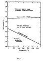
- FIG. 2 represents the diagram of the hydrogen thermodynamic data , i.e. hydrogen production by electrolysis as function of the temperature.
- the electrolysis occurs with heat evolution, heat which must be taken away; whereas for voltage within the thermo-neutral line and the reversible potential line the production of hydrogen occurs by adsorbing both heat and electricity.
- the low solubility of H 2 and O 2 in the electrolyte decreases their concentration and hinders their migration towards the reaction centers especially on the cathodes hot spots where the O 2 reduces to OH - and migrates towards the anodes to react with the hydrogen oxidized to form water.
- the overall transformation of chemical energy into electric energy is hindered and consequently the yield of the fuel cell decreases.
- the electrochemical cell according to the invention cools the hot-spots since it solves this problems by applying on the electrolyte side an overpressure dP (the gas side has the working pressure P) followed by an overpressure dp lower than dP.
- the higher overpressure dP, acting on the electrolyte causes the flow of the electrolyte towards the interior of the porous electrode, crossing at the beginning the hydrophobic macro-and micro-porosities and further flowing into the hydrophilic metal catalytic clusters.
- the electrolyte flows back, as the result of the hydrophobic capillary forces and of the hydraulic phenomena of the hydrophilic catalytic clusters.
- the electrolyte fluctuations inside of the porous electrodes determine volumes for the heterogeneous catalytic reactions that drop the electrodic overvoltages, improve the kinetics while the electrodes are quite isothermic.
- a catalytic electrode volume has been generated, which replaces the interface of the three phases of the static process and determines the anodic activation (heat supply for the electrolysis) and cathodic activation (cold supply for the synthesis).
- the heat exchange is concerning the catalytic metal clusters of the O 2 -porous electrodes where the entropy variation heats are very much greater than the H 2 -porous electrodes and where the electrodic overvoltages are big in the static process.
- the innovation improves the catalytic activity and kinetic enhancement of the electrochemical reactions.
- the frequency of the pressure modulation varies between few Hertz up to some tens of Hertz, in the range from 1 to 50/60 Hz, whereas the pressure difference dP - dp, in the inter-electrodic space, varies from 1 meter up to some tens of meters of liquid heads, in the range from 1 to 30 m.
- the electrodes are porous carbon based and there are some examples : the porosity varies around 1-10 nm for the transport hydrophilic layers at the electrolyte side as well as around 1-20 nm for the diffusive and transport hydrophobic layers at the gas side onto the metallic mesh of current distribution.
- the intermediate catalytic layers have hydrophobic and hydrophilic micro-porosities 0.1 - I nm, whereas the catalytic and hydrophilic porosities have dimensions around 0.01-0.005 nm, where is concentrated mostly the total catalytic surface.
- the electrodes are produced by synterising carbon powders, which have been previously activated with catalytic metals or compounds known in the art and consequently brought together with PTFE or similar binders using process known in the art and described in International J. Hydrogen Energy, Vol. 10, No. 5, pp. 317-324, 1985 .
- the produced or consumed current is limited to 0,2-0,3 A/cm 2 (technical current) in order to maximize the energy quota which goes to useful work.
- the electrodic current can be higher than the technical current and the delivered voltage in the fuel cell increases up to 0.9 V when a pressure modulation is applied to the cell, whereas for the equal value of current density the voltage in the same fuel cell, without pressure modulation, is of 0.7 V.
- the electric yield (EL.Y) is respectively the ratio V cell /E rev for the fuel cell - AFC and E rev /V cell for the electrolysis cell- AEC and the energetic yield (EN.Y) is the ratio V cell /V hhv for the AFC e V hhv /V cell for the AEC where V hhv equals the thermo-neutral potential.
- FC s FCd EC s EC d EL.Y from 59% to 76% from 62% to 84% EN.Y from 47% to 60% from 78% to 106%
- the energy consumption drops more than 1 K Wh/Nm 3 H 2 , in other words the efficiency increases of 35% and the overall conversion of electric energy into chemical energy is higher than 80%.
- the electrolysis occurs because of the combined action of heat and electric energy supply.
- the electrochemical cell according to the invention can advantageously be used either as electrolyser or as fuel cell using the same low cost electrodes which show a higher durability.
- the cell according to the invention has intrinsic security due to the higher pressure at the electrolyte side with regards to the gas side of the porous electrodes because of the hydrophobic character of the electrodes and the cell is intrinsically safe and does not necessitate the use of costly membranes or diaphragms for separating anodes and cathodes.
- a software program commands the timing of the pulses modulator at the frequency "f” and controls the electrolytic overpressures difference "dP - dp".
- a data acquisition board does all data logging including the electrical quantities in order to optimize the power and the energy quota which transforms into useful work in agreement with the needs of the plant.
- the dynamic modulation of the electrolyte within the pores of the electrodes increases the efficiency of the electrochemical cell since the contact time of the multi-phase interface gas + liquid + solid active centers is approaching the reaction times of the electrochemical reactions.
- the heat exchange within the porosity of the electrodes has improved and the decrease of cold- or hot-spots has enhanced the life of the electrodes; the specific reactive surface per volume unity is increased and the mass transport of reactants and reaction products is superior.
- the electrochemical cells according to the invention can be advantageously integrated in the present energy production systems which produce heat as waste by-product, such as the nuclear and conventional thermo-generating energy plants.
- This waste heat can be used as heat source in the electrolysis cells according to the invention increasing the overall energy yield.
- the surplus electric energy produced by the power stations in off-peak hours can be used in a bi-functional Electrolysis/Synthesis plant according to the invention, which turns out the surplus energy into hydrogen and oxygen directly at high pressure, that can be used, when needed during the peak hours, to generate electric energy using the fuel cells according to the invention.
- the invention puts together Electrochemistry & Electronics realizing the energy savings either in the chemical industry, in the automotive industry, in the residential power generation and in the nuclear and thermo power generators through the above described enhanced use of heat.
Landscapes
- Chemical & Material Sciences (AREA)
- Chemical Kinetics & Catalysis (AREA)
- Electrochemistry (AREA)
- Engineering & Computer Science (AREA)
- General Chemical & Material Sciences (AREA)
- Materials Engineering (AREA)
- Organic Chemistry (AREA)
- Metallurgy (AREA)
- Sustainable Development (AREA)
- Life Sciences & Earth Sciences (AREA)
- Manufacturing & Machinery (AREA)
- Sustainable Energy (AREA)
- Inorganic Chemistry (AREA)
- Electrolytic Production Of Non-Metals, Compounds, Apparatuses Therefor (AREA)
- Fuel Cell (AREA)
- Inert Electrodes (AREA)
- Transducers For Ultrasonic Waves (AREA)
- Primary Cells (AREA)
Claims (13)
- Elektrochemische Zellenmodule, bestehend aus Paaren von porösen katalytischen Mehrschichtelektroden, welche die Anoden und die Katoden bilden und äußere und innere Gasbereiche, welche den Elektrolyt enthalten, abgrenzen und durch eine externe elektrische Schaltung verbunden sind, dadurch gekennzeichnet, dass diese Zellmodule umfassen:• Druckmodulatoren, welche im Gebrauch zwei Druckzyklen erzeugen, die unabhängig, jedoch mit entgegengesetzt gerichteter Phase synchronisiert sind und an der Eintrittsstelle und an der Austrittsstelle des zirkulierenden Elektrolyten wirken,• poröse Mehrschichtelektroden, die auf der Gasseite Wasser abgeben, und• Mittel für den Wärmeaustausch in den porösen Elektroden der Zellmodule über den in die elektrochemische Zelle hinein fließenden Elektrolyten.
- Elektrochemische Zelle nach Anspruch 1, bei welcher:• die porösen Mehrschichtelektroden auf der Gasseite leitend und hydrophob sind,• die leitenden und katalytischen Mittelschichten hydrophob und hydrophil sind und• sich auf der Elektrolytseite eine nichtleitende, nichtkatalytische und vorzugsweise hydrophile Schicht befindet.
- Elektrochemische Zelle nach den Ansprüchen 1 - 2, bei welcher die Druckmodulatoren mit zwei Tanks verbunden sind, welche im Gebrauch den Elektrolyten unter zwei unterschiedlichen Drücken enthalten und jeder jeweils an den Eingang und den Ausgang der Zelle über ein Ventil angeschlossen ist.
- Elektrochemische Zelle nach Anspruch 3, bei welcher die Öffnungsquerschnitte des Austrittsventils S und des Eintrittsventils s dergestalt ausgelegt sind, dass S > s ist.
- Elektrochemische Zelle nach den Ansprüchen 1 - 4, bei welcher die Druckmodulatoren im Gebrauch bei einer Frequenz im Bereich von 1 - 60 Hz, vorzugsweise im Bereich von 1 - 50 Hz modulieren.
- Elektrochemische Zelle nach den Ansprüchen 1 - 5, bei welcher• im Gebrauch eine Energiequelle den porösen Elektroden einen äußeren Gleichstrom dergestalt zuführt, dass an der Katode die Bildung von H2 und an der Anode die Bildung von O2 erfolgt, und• im Gebrauch der Elektrolyt eine wässerige KOH-Lösung ist.
- Elektrochemische Zelle nach Anspruch 6, bei welcher die Zelle ein Elektrolyseur ist.
- Elektrochemische Zelle nach den Ansprüchen 1 - 5, bei welcher• der Elektrolyt eine wässerige KOH-Lösung ist und• aus den porösen Elektroden elektrische Energie gezogen wird, indem den Gasseiten der Elektroden H2 bzw. O2 zugeführt wird.
- Elektrochemische Zelle nach Anspruch 8, bei welcher die Zelle eine Brennstoffzelle ist.
- Elektrochemischer Vorgang, bei welchem die elektrochemischen Zellen der Ansprüche 1 bis 9 genutzt werden und welcher die folgenden Schritte umfasst:• Aufrechterhaltung eines Druckes P bis zu 200 Bar auf der Gasseite;• Veränderung des Elektrolytdrucks auf der Innenseite auf diskontinuierliche Weise im Bereich P+dP und P+dp;• Erzeugung von positiven Wellen der Amplitude dP und dp mit der Frequenz f auf dem Elektrolytdruck; wenn ein Ventil offen ist, ist das andere geschlossen ist bzw. umgekehrt;• Wärmeaustausch in den porösen Elektroden der Zellmodule über den in die elektrochemische Zelle einfließenden Elektrolyt.
- Elektrochemischer Vorgang nach Anspruch 10, bei welchem die Überdrücke dergestalt sind, dass dP > dp, wobei vorzugsweise die zwei Überdrücke für Zyklen der Länge τdP und τdp anliegen, wobei τdP < τdp bei der Frequenz f = 1/T und T = τdP + τdp sind, wobei stärker vorzuziehen ist, dass die zwei Überdrücke bei einer Frequenz im Bereich von 1 - 60 Hz, vorzugsweise im Bereich von 1 - 50 Hz anliegen.
- Elektrochemischer Vorgang nach den Ansprüchen 10 bis 11, bei welchem:• Wärme von außen zugeführt wird,• eine Energiequelle den porösen Elektroden einen äußeren Gleichstrom dergestalt zuführt, dass an der negativen Elektrode die Bildung von H2 und an der positiven Elektrode die Bildung von O2 erfolgt, und• der Elektrolyt eine wässerige KOH-Lösung ist.
- Elektrochemischer Vorgang nach den Ansprüchen 10 bis 11, bei welchem• der Elektrolyt eine wässerige KOH-Lösung ist und• aus den porösen Elektroden elektrische Energie gezogen wird, indem den Gasseiten der Elektroden H2 bzw. O2 zugeführt wird.
Applications Claiming Priority (2)
| Application Number | Priority Date | Filing Date | Title |
|---|---|---|---|
| IT000006A ITPV20030006A1 (it) | 2003-06-24 | 2003-06-24 | Movimentazione e temporizzazione degli afflussi e riflussi dell'elettrolita all'interno di elettrodi porosi a gas. |
| PCT/EP2004/051207 WO2004113590A2 (en) | 2003-06-24 | 2004-06-23 | Electrochemical thermodynamo |
Publications (3)
| Publication Number | Publication Date |
|---|---|
| EP1711972A2 EP1711972A2 (de) | 2006-10-18 |
| EP1711972B1 true EP1711972B1 (de) | 2010-02-10 |
| EP1711972B9 EP1711972B9 (de) | 2011-11-16 |
Family
ID=33524058
Family Applications (1)
| Application Number | Title | Priority Date | Filing Date |
|---|---|---|---|
| EP04741868A Expired - Lifetime EP1711972B9 (de) | 2003-06-24 | 2004-06-23 | Elektrochemischer thermo-dynamo |
Country Status (8)
| Country | Link |
|---|---|
| US (2) | US8034220B2 (de) |
| EP (1) | EP1711972B9 (de) |
| AT (1) | ATE457532T1 (de) |
| CA (1) | CA2545114C (de) |
| DE (1) | DE602004025512D1 (de) |
| ES (1) | ES2342774T3 (de) |
| IT (1) | ITPV20030006A1 (de) |
| WO (1) | WO2004113590A2 (de) |
Families Citing this family (15)
| Publication number | Priority date | Publication date | Assignee | Title |
|---|---|---|---|---|
| ITPV20030006A1 (it) * | 2003-06-24 | 2004-12-25 | Mario Melosi | Movimentazione e temporizzazione degli afflussi e riflussi dell'elettrolita all'interno di elettrodi porosi a gas. |
| FR2919617B1 (fr) * | 2007-08-02 | 2009-11-20 | Commissariat Energie Atomique | Electrolyseur haute temperature et haute pression a fonctionnement allothermique |
| FR2919618B1 (fr) * | 2007-08-02 | 2009-11-13 | Commissariat Energie Atomique | Electrolyseur haute temperature et haute pression a fonctionnement allothermique et forte capacite de production |
| US20100084282A1 (en) * | 2008-10-08 | 2010-04-08 | Nhthree, Llc | Method and apparatus for dissociating water |
| ITMI20090243A1 (it) * | 2009-02-20 | 2010-08-21 | Henergy Srl | Elettrodo poroso con trasporto di gas e di elettrolita |
| CA2824007C (en) | 2011-02-04 | 2019-02-19 | Afc Energy Plc | Fuel cell electrodes |
| WO2013185169A1 (en) * | 2012-06-12 | 2013-12-19 | Monash University | Gas permeable electrode and method of manufacture |
| AU2012382382A1 (en) | 2012-06-12 | 2015-01-15 | Aquahydrex Pty Ltd | Breathable electrode and method for use in water splitting |
| KR20160040614A (ko) | 2013-07-31 | 2016-04-14 | 아쿠아하이드렉스 프로프라이어터리 리미티드 | 기체 확산 전극(들)을 가지는 전기-합성 또는 전기-에너지 전지 |
| CN105579125B (zh) * | 2013-09-06 | 2019-04-19 | 株式会社M光能源开发研究所 | 装备疏液性多孔膜的电化学反应器 |
| DE102013226357A1 (de) * | 2013-12-18 | 2015-06-18 | Siemens Aktiengesellschaft | Pulsierende Elektrolytzufuhr in den Reaktionsraum einer Elektrolysezelle mit gasentwickelnden Elektroden |
| US11692741B2 (en) * | 2018-07-31 | 2023-07-04 | Netech, Inc. | Heat generation method and device using ionic vacancies generated by electrochemical reaction |
| CA3127358A1 (en) | 2019-02-01 | 2020-08-06 | Aquahydrex, Inc. | Electrochemical system with confined electrolyte |
| IT202100027230A1 (it) | 2021-10-22 | 2023-04-22 | Dragoni Matteo | Celle elettro-chimiche reversibili ad alta efficienza di tensione, elettrolizzatore e rispettivo metodo per la produzione di idrogeno |
| GB2619145A (en) * | 2021-12-22 | 2023-11-29 | Francis Geary Paul | Flow through electrode stack |
Family Cites Families (7)
| Publication number | Priority date | Publication date | Assignee | Title |
|---|---|---|---|---|
| BE636538A (de) * | 1962-08-27 | |||
| US3391028A (en) * | 1963-05-01 | 1968-07-02 | Richard S. Vose | Fuel cell and method of producing electricity |
| FR1452701A (fr) * | 1965-07-15 | 1966-04-15 | Azote Office Nat Ind | Perfectionnements aux piles à combustibles |
| DE2321087A1 (de) * | 1973-04-26 | 1974-11-14 | Varta Batterie | Brennstoffzellenaggregat |
| US3905884A (en) * | 1974-11-20 | 1975-09-16 | United Technologies Corp | Electrolysis cell system including recirculating product gas stream for cooling the cell |
| US4042481A (en) * | 1974-12-24 | 1977-08-16 | Kelly Donald A | Pressure-electrolysis cell-unit |
| ITPV20030006A1 (it) * | 2003-06-24 | 2004-12-25 | Mario Melosi | Movimentazione e temporizzazione degli afflussi e riflussi dell'elettrolita all'interno di elettrodi porosi a gas. |
-
2003
- 2003-06-24 IT IT000006A patent/ITPV20030006A1/it unknown
-
2004
- 2004-06-23 US US10/578,548 patent/US8034220B2/en not_active Expired - Fee Related
- 2004-06-23 DE DE602004025512T patent/DE602004025512D1/de not_active Expired - Lifetime
- 2004-06-23 EP EP04741868A patent/EP1711972B9/de not_active Expired - Lifetime
- 2004-06-23 CA CA2545114A patent/CA2545114C/en not_active Expired - Fee Related
- 2004-06-23 AT AT04741868T patent/ATE457532T1/de not_active IP Right Cessation
- 2004-06-23 ES ES04741868T patent/ES2342774T3/es not_active Expired - Lifetime
- 2004-06-23 WO PCT/EP2004/051207 patent/WO2004113590A2/en not_active Ceased
-
2011
- 2011-09-13 US US13/231,555 patent/US8613841B2/en not_active Expired - Fee Related
Also Published As
| Publication number | Publication date |
|---|---|
| US20070080069A1 (en) | 2007-04-12 |
| ES2342774T3 (es) | 2010-07-14 |
| CA2545114C (en) | 2014-04-01 |
| US8034220B2 (en) | 2011-10-11 |
| EP1711972A2 (de) | 2006-10-18 |
| CA2545114A1 (en) | 2004-12-29 |
| ATE457532T1 (de) | 2010-02-15 |
| WO2004113590A2 (en) | 2004-12-29 |
| ITPV20030006A1 (it) | 2004-12-25 |
| US20120052335A1 (en) | 2012-03-01 |
| US8613841B2 (en) | 2013-12-24 |
| DE602004025512D1 (de) | 2010-03-25 |
| EP1711972B9 (de) | 2011-11-16 |
| WO2004113590A3 (en) | 2005-08-11 |
Similar Documents
| Publication | Publication Date | Title |
|---|---|---|
| US8613841B2 (en) | Electrochemical thermodynamo | |
| Zhang et al. | Redox-mediated water splitting for decoupled H2 production | |
| EP2398938B1 (de) | Vorrichtung und verfahren zur gaserfassung während einer elektrolyse | |
| US9133552B2 (en) | Electrolytic cell and method of use thereof | |
| US20190006695A1 (en) | Method and system for efficiently operating electrochemical cells | |
| US9416457B2 (en) | System and method for renewable resource production, for example, hydrogen production by microbial, electrolysis, fermentation, and/or photosynthesis | |
| US20240229257A1 (en) | Photo-electrochemical cell and corresponding apparatus | |
| Siddiqui et al. | Experimental investigation of an integrated solar powered clean hydrogen to ammonia synthesis system | |
| Zhao et al. | Automatic operation of decoupled water electrolysis based on bipolar electrode | |
| Xia et al. | Entropy-directed metal–organic frameworks drive solar-electrolytic water splitting | |
| EP2534099A2 (de) | System und verfahren zur herstellung erneuerbarer ressourcen, z. b. von wasserstoff durch mikrobielle elektrolyse, fermentierung und/oder photosynthese | |
| Sunny et al. | Device engineering and mechanisms for electrocatalytic water splitting: conventional to decoupled electrolyzer | |
| Austin | Fuel cells-A review of government-sponsored research, 1950-1964 | |
| CN116043259B (zh) | 基于Ni(OH)2氧化还原媒介转化PET废塑料制备甲酸和氢气的方法 | |
| Ahmed et al. | Advancements in Electrode Development for Water Electrolysis: From Support Electrodes to Self‐Supported Electrodes | |
| CN209929411U (zh) | 一种基于固体氢技术的燃料电池的发电系统 | |
| Rohilla et al. | Design, Multi-scale Modeling, and Up-Scaling | |
| Pruss et al. | 3D multiphase simulation of a bipolar membrane water electrolyzer | |
| Κομιχείλη | Hydrogen energy: advances in nanotechnology for hydrogen storage | |
| Xiang et al. | Sustainable Energy & Fuels | |
| Fellet et al. | Power-to-gas plants use renewable energy to make sustainable fuel | |
| Srinivasan et al. | HYDROGEN PRODUCTION, STORAGE, AND CONVERSION FOR |
Legal Events
| Date | Code | Title | Description |
|---|---|---|---|
| PUAI | Public reference made under article 153(3) epc to a published international application that has entered the european phase |
Free format text: ORIGINAL CODE: 0009012 |
|
| 17P | Request for examination filed |
Effective date: 20060502 |
|
| AK | Designated contracting states |
Kind code of ref document: A2 Designated state(s): AT BE BG CH CY CZ DE DK EE ES FI FR GB GR HU IE IT LI LU MC NL PL PT RO SE SI SK TR |
|
| 17Q | First examination report despatched |
Effective date: 20061010 |
|
| REG | Reference to a national code |
Ref country code: HK Ref legal event code: DE Ref document number: 1095614 Country of ref document: HK |
|
| APBN | Date of receipt of notice of appeal recorded |
Free format text: ORIGINAL CODE: EPIDOSNNOA2E |
|
| APBR | Date of receipt of statement of grounds of appeal recorded |
Free format text: ORIGINAL CODE: EPIDOSNNOA3E |
|
| APAF | Appeal reference modified |
Free format text: ORIGINAL CODE: EPIDOSCREFNE |
|
| APBT | Appeal procedure closed |
Free format text: ORIGINAL CODE: EPIDOSNNOA9E |
|
| GRAP | Despatch of communication of intention to grant a patent |
Free format text: ORIGINAL CODE: EPIDOSNIGR1 |
|
| GRAS | Grant fee paid |
Free format text: ORIGINAL CODE: EPIDOSNIGR3 |
|
| GRAA | (expected) grant |
Free format text: ORIGINAL CODE: 0009210 |
|
| AK | Designated contracting states |
Kind code of ref document: B1 Designated state(s): AT BE BG CH CY CZ DE DK EE ES FI FR GB GR HU IE IT LI LU MC NL PL PT RO SE SI SK TR |
|
| REG | Reference to a national code |
Ref country code: GB Ref legal event code: FG4D |
|
| REG | Reference to a national code |
Ref country code: CH Ref legal event code: EP |
|
| REG | Reference to a national code |
Ref country code: IE Ref legal event code: FG4D |
|
| REF | Corresponds to: |
Ref document number: 602004025512 Country of ref document: DE Date of ref document: 20100325 Kind code of ref document: P |
|
| REG | Reference to a national code |
Ref country code: NL Ref legal event code: VDEP Effective date: 20100210 |
|
| REG | Reference to a national code |
Ref country code: ES Ref legal event code: FG2A Ref document number: 2342774 Country of ref document: ES Kind code of ref document: T3 |
|
| PG25 | Lapsed in a contracting state [announced via postgrant information from national office to epo] |
Ref country code: PT Free format text: LAPSE BECAUSE OF FAILURE TO SUBMIT A TRANSLATION OF THE DESCRIPTION OR TO PAY THE FEE WITHIN THE PRESCRIBED TIME-LIMIT Effective date: 20100611 |
|
| PG25 | Lapsed in a contracting state [announced via postgrant information from national office to epo] |
Ref country code: FI Free format text: LAPSE BECAUSE OF FAILURE TO SUBMIT A TRANSLATION OF THE DESCRIPTION OR TO PAY THE FEE WITHIN THE PRESCRIBED TIME-LIMIT Effective date: 20100210 Ref country code: AT Free format text: LAPSE BECAUSE OF FAILURE TO SUBMIT A TRANSLATION OF THE DESCRIPTION OR TO PAY THE FEE WITHIN THE PRESCRIBED TIME-LIMIT Effective date: 20100210 Ref country code: SI Free format text: LAPSE BECAUSE OF FAILURE TO SUBMIT A TRANSLATION OF THE DESCRIPTION OR TO PAY THE FEE WITHIN THE PRESCRIBED TIME-LIMIT Effective date: 20100210 Ref country code: PL Free format text: LAPSE BECAUSE OF FAILURE TO SUBMIT A TRANSLATION OF THE DESCRIPTION OR TO PAY THE FEE WITHIN THE PRESCRIBED TIME-LIMIT Effective date: 20100210 |
|
| RAP2 | Party data changed (patent owner data changed or rights of a patent transferred) |
Owner name: HYSYTECH S.R.L. Owner name: ANNAS S.R.L. Owner name: RICOTTI, PAOLO |
|
| PG25 | Lapsed in a contracting state [announced via postgrant information from national office to epo] |
Ref country code: EE Free format text: LAPSE BECAUSE OF FAILURE TO SUBMIT A TRANSLATION OF THE DESCRIPTION OR TO PAY THE FEE WITHIN THE PRESCRIBED TIME-LIMIT Effective date: 20100210 Ref country code: BE Free format text: LAPSE BECAUSE OF FAILURE TO SUBMIT A TRANSLATION OF THE DESCRIPTION OR TO PAY THE FEE WITHIN THE PRESCRIBED TIME-LIMIT Effective date: 20100210 Ref country code: SE Free format text: LAPSE BECAUSE OF FAILURE TO SUBMIT A TRANSLATION OF THE DESCRIPTION OR TO PAY THE FEE WITHIN THE PRESCRIBED TIME-LIMIT Effective date: 20100210 Ref country code: CY Free format text: LAPSE BECAUSE OF FAILURE TO SUBMIT A TRANSLATION OF THE DESCRIPTION OR TO PAY THE FEE WITHIN THE PRESCRIBED TIME-LIMIT Effective date: 20100210 Ref country code: GR Free format text: LAPSE BECAUSE OF FAILURE TO SUBMIT A TRANSLATION OF THE DESCRIPTION OR TO PAY THE FEE WITHIN THE PRESCRIBED TIME-LIMIT Effective date: 20100511 Ref country code: NL Free format text: LAPSE BECAUSE OF FAILURE TO SUBMIT A TRANSLATION OF THE DESCRIPTION OR TO PAY THE FEE WITHIN THE PRESCRIBED TIME-LIMIT Effective date: 20100210 Ref country code: RO Free format text: LAPSE BECAUSE OF FAILURE TO SUBMIT A TRANSLATION OF THE DESCRIPTION OR TO PAY THE FEE WITHIN THE PRESCRIBED TIME-LIMIT Effective date: 20100210 |
|
| PG25 | Lapsed in a contracting state [announced via postgrant information from national office to epo] |
Ref country code: CZ Free format text: LAPSE BECAUSE OF FAILURE TO SUBMIT A TRANSLATION OF THE DESCRIPTION OR TO PAY THE FEE WITHIN THE PRESCRIBED TIME-LIMIT Effective date: 20100210 Ref country code: BG Free format text: LAPSE BECAUSE OF FAILURE TO SUBMIT A TRANSLATION OF THE DESCRIPTION OR TO PAY THE FEE WITHIN THE PRESCRIBED TIME-LIMIT Effective date: 20100510 Ref country code: SK Free format text: LAPSE BECAUSE OF FAILURE TO SUBMIT A TRANSLATION OF THE DESCRIPTION OR TO PAY THE FEE WITHIN THE PRESCRIBED TIME-LIMIT Effective date: 20100210 |
|
| PLBE | No opposition filed within time limit |
Free format text: ORIGINAL CODE: 0009261 |
|
| STAA | Information on the status of an ep patent application or granted ep patent |
Free format text: STATUS: NO OPPOSITION FILED WITHIN TIME LIMIT |
|
| REG | Reference to a national code |
Ref country code: GB Ref legal event code: 732E Free format text: REGISTERED BETWEEN 20101216 AND 20101222 |
|
| 26N | No opposition filed |
Effective date: 20101111 |
|
| PG25 | Lapsed in a contracting state [announced via postgrant information from national office to epo] |
Ref country code: MC Free format text: LAPSE BECAUSE OF NON-PAYMENT OF DUE FEES Effective date: 20100630 Ref country code: DK Free format text: LAPSE BECAUSE OF FAILURE TO SUBMIT A TRANSLATION OF THE DESCRIPTION OR TO PAY THE FEE WITHIN THE PRESCRIBED TIME-LIMIT Effective date: 20100210 |
|
| PG25 | Lapsed in a contracting state [announced via postgrant information from national office to epo] |
Ref country code: IT Free format text: LAPSE BECAUSE OF FAILURE TO SUBMIT A TRANSLATION OF THE DESCRIPTION OR TO PAY THE FEE WITHIN THE PRESCRIBED TIME-LIMIT Effective date: 20100210 |
|
| PG25 | Lapsed in a contracting state [announced via postgrant information from national office to epo] |
Ref country code: IE Free format text: LAPSE BECAUSE OF NON-PAYMENT OF DUE FEES Effective date: 20100623 |
|
| PG25 | Lapsed in a contracting state [announced via postgrant information from national office to epo] |
Ref country code: LU Free format text: LAPSE BECAUSE OF NON-PAYMENT OF DUE FEES Effective date: 20100623 Ref country code: HU Free format text: LAPSE BECAUSE OF FAILURE TO SUBMIT A TRANSLATION OF THE DESCRIPTION OR TO PAY THE FEE WITHIN THE PRESCRIBED TIME-LIMIT Effective date: 20100811 |
|
| PG25 | Lapsed in a contracting state [announced via postgrant information from national office to epo] |
Ref country code: TR Free format text: LAPSE BECAUSE OF FAILURE TO SUBMIT A TRANSLATION OF THE DESCRIPTION OR TO PAY THE FEE WITHIN THE PRESCRIBED TIME-LIMIT Effective date: 20100210 |
|
| REG | Reference to a national code |
Ref country code: HK Ref legal event code: WD Ref document number: 1095614 Country of ref document: HK |
|
| REG | Reference to a national code |
Ref country code: FR Ref legal event code: PLFP Year of fee payment: 12 |
|
| REG | Reference to a national code |
Ref country code: FR Ref legal event code: PLFP Year of fee payment: 13 |
|
| REG | Reference to a national code |
Ref country code: FR Ref legal event code: PLFP Year of fee payment: 14 |
|
| PGFP | Annual fee paid to national office [announced via postgrant information from national office to epo] |
Ref country code: CH Payment date: 20170613 Year of fee payment: 14 Ref country code: GB Payment date: 20170621 Year of fee payment: 14 Ref country code: FR Payment date: 20170511 Year of fee payment: 14 |
|
| PGFP | Annual fee paid to national office [announced via postgrant information from national office to epo] |
Ref country code: ES Payment date: 20170704 Year of fee payment: 14 Ref country code: DE Payment date: 20170621 Year of fee payment: 14 |
|
| REG | Reference to a national code |
Ref country code: DE Ref legal event code: R119 Ref document number: 602004025512 Country of ref document: DE |
|
| REG | Reference to a national code |
Ref country code: CH Ref legal event code: PL |
|
| GBPC | Gb: european patent ceased through non-payment of renewal fee |
Effective date: 20180623 |
|
| PG25 | Lapsed in a contracting state [announced via postgrant information from national office to epo] |
Ref country code: DE Free format text: LAPSE BECAUSE OF NON-PAYMENT OF DUE FEES Effective date: 20190101 Ref country code: CH Free format text: LAPSE BECAUSE OF NON-PAYMENT OF DUE FEES Effective date: 20180630 Ref country code: LI Free format text: LAPSE BECAUSE OF NON-PAYMENT OF DUE FEES Effective date: 20180630 Ref country code: FR Free format text: LAPSE BECAUSE OF NON-PAYMENT OF DUE FEES Effective date: 20180630 Ref country code: GB Free format text: LAPSE BECAUSE OF NON-PAYMENT OF DUE FEES Effective date: 20180623 |
|
| REG | Reference to a national code |
Ref country code: ES Ref legal event code: FD2A Effective date: 20190916 |
|
| PG25 | Lapsed in a contracting state [announced via postgrant information from national office to epo] |
Ref country code: ES Free format text: LAPSE BECAUSE OF NON-PAYMENT OF DUE FEES Effective date: 20180624 |