EP1710377A2 - Power closure latch assembly - Google Patents
Power closure latch assembly Download PDFInfo
- Publication number
- EP1710377A2 EP1710377A2 EP20060251595 EP06251595A EP1710377A2 EP 1710377 A2 EP1710377 A2 EP 1710377A2 EP 20060251595 EP20060251595 EP 20060251595 EP 06251595 A EP06251595 A EP 06251595A EP 1710377 A2 EP1710377 A2 EP 1710377A2
- Authority
- EP
- European Patent Office
- Prior art keywords
- lever
- latch
- driving member
- power
- latch assembly
- Prior art date
- Legal status (The legal status is an assumption and is not a legal conclusion. Google has not performed a legal analysis and makes no representation as to the accuracy of the status listed.)
- Withdrawn
Links
Images


Classifications
-
- E—FIXED CONSTRUCTIONS
- E05—LOCKS; KEYS; WINDOW OR DOOR FITTINGS; SAFES
- E05B—LOCKS; ACCESSORIES THEREFOR; HANDCUFFS
- E05B81/00—Power-actuated vehicle locks
- E05B81/12—Power-actuated vehicle locks characterised by the function or purpose of the powered actuators
- E05B81/20—Power-actuated vehicle locks characterised by the function or purpose of the powered actuators for assisting final closing or for initiating opening
-
- E—FIXED CONSTRUCTIONS
- E05—LOCKS; KEYS; WINDOW OR DOOR FITTINGS; SAFES
- E05B—LOCKS; ACCESSORIES THEREFOR; HANDCUFFS
- E05B81/00—Power-actuated vehicle locks
- E05B81/54—Electrical circuits
- E05B81/90—Manual override in case of power failure
-
- E—FIXED CONSTRUCTIONS
- E05—LOCKS; KEYS; WINDOW OR DOOR FITTINGS; SAFES
- E05B—LOCKS; ACCESSORIES THEREFOR; HANDCUFFS
- E05B47/00—Operating or controlling locks or other fastening devices by electric or magnetic means
- E05B47/0001—Operating or controlling locks or other fastening devices by electric or magnetic means with electric actuators; Constructional features thereof
- E05B2047/0014—Constructional features of actuators or power transmissions therefor
- E05B2047/0015—Output elements of actuators
- E05B2047/0017—Output elements of actuators with rotary motion
-
- E—FIXED CONSTRUCTIONS
- E05—LOCKS; KEYS; WINDOW OR DOOR FITTINGS; SAFES
- E05B—LOCKS; ACCESSORIES THEREFOR; HANDCUFFS
- E05B47/00—Operating or controlling locks or other fastening devices by electric or magnetic means
- E05B47/0001—Operating or controlling locks or other fastening devices by electric or magnetic means with electric actuators; Constructional features thereof
- E05B2047/0014—Constructional features of actuators or power transmissions therefor
- E05B2047/0018—Details of actuator transmissions
- E05B2047/0026—Clutches, couplings or braking arrangements
-
- E—FIXED CONSTRUCTIONS
- E05—LOCKS; KEYS; WINDOW OR DOOR FITTINGS; SAFES
- E05B—LOCKS; ACCESSORIES THEREFOR; HANDCUFFS
- E05B47/00—Operating or controlling locks or other fastening devices by electric or magnetic means
- E05B47/0001—Operating or controlling locks or other fastening devices by electric or magnetic means with electric actuators; Constructional features thereof
- E05B47/0012—Operating or controlling locks or other fastening devices by electric or magnetic means with electric actuators; Constructional features thereof with rotary electromotors
-
- E—FIXED CONSTRUCTIONS
- E05—LOCKS; KEYS; WINDOW OR DOOR FITTINGS; SAFES
- E05B—LOCKS; ACCESSORIES THEREFOR; HANDCUFFS
- E05B81/00—Power-actuated vehicle locks
- E05B81/24—Power-actuated vehicle locks characterised by constructional features of the actuator or the power transmission
- E05B81/32—Details of the actuator transmission
- E05B81/46—Clutches
-
- Y—GENERAL TAGGING OF NEW TECHNOLOGICAL DEVELOPMENTS; GENERAL TAGGING OF CROSS-SECTIONAL TECHNOLOGIES SPANNING OVER SEVERAL SECTIONS OF THE IPC; TECHNICAL SUBJECTS COVERED BY FORMER USPC CROSS-REFERENCE ART COLLECTIONS [XRACs] AND DIGESTS
- Y10—TECHNICAL SUBJECTS COVERED BY FORMER USPC
- Y10T—TECHNICAL SUBJECTS COVERED BY FORMER US CLASSIFICATION
- Y10T292/00—Closure fasteners
- Y10T292/08—Bolts
- Y10T292/1043—Swinging
- Y10T292/1044—Multiple head
- Y10T292/1045—Operating means
- Y10T292/1047—Closure
Definitions
- the present invention relates to latches, and in particular, but not exclusively, to vehicle door latches.
- Known vehicle doors include elastomeric door seals secured to the periphery of the door which are compressed when the doors close and the seals come into contact with the periphery of the door aperture.
- Modem trends in automobile manufacture require high door seal loads to reduce wind generated noise when the vehicle is moving. As a result, increased force must be applied to the door when closed by the operator in order to ensure that the latch mechanism has secured the door shut.
- a consequence of higher seal loads is that the operator is required to apply an increasingly high load to the door in order to ensure the latch secures the door shut.
- a known solution to this problem is to provide a power closing latch mechanism which drives the latch from a latched safety position, also known as a first safety position, (achieved by the operator gently closing the door), to a fully latched position.
- the shut load (the load required to compress the door seals and to drive the latch to the closed condition) is overcome by the power actuator, rather than the operator.
- existing latches have been known to fail during the power close operation rendering impossible the subsequent manual opening of the door latch by the operator.
- latches In order to over come these high loads known latches employ long lever arms to generate sufficient force to close the latch. This results in larger latches which require a sizeable space envelope in the door and add weight to the door.
- An object of the present invention is to provide an improved form of latch arrangement which at least mitigates the problems outlined above.
- a further object is to provide a simple and/or easily operable means of disengaging a power closure mechanism for a latch in the event of failure.
- a further object of the present invention is to provide a drive mechanism for a power closure latch assembly which provides a more space efficient method of driving the latch assembly.
- a latch assembly including a latch bolt for engaging an associated striker, the latch bolt having an open position, a safety position and a closed position, which positions correspond to an open condition, a safety condition and closed condition, respectively, in the latch assembly; the latch assembly further comprising: a pawl for releasably retaining the latch bolt in the safety position and the closed position; a power closure mechanism for applying a drive load to the latch bolt to drive the latch bolt from the safety position to the closed position, said power closure mechanism further comprising; a pivotably mounted driving member with a first portion which in use abuts against the latch bolt in response to powered closure; where said powered closure results from movement of the pivot of the driving member combined with abutment of a second portion of the driving member against a bearing surface or support means.
- a clutch stop lever is arranged for escapable engagement with the power closure mechanism.
- the power closure mechanism may have an actuable state in which the clutch stop lever is engageable with the power closure mechanism, and an escaped state in which the clutch stop lever is not engageable with the power closure mechanism.
- the power closure mechanism may provide support means for supporting the driving member when the clutch stop lever is engaged with the power closure mechanism, so as to allow the driving member to drive the latch bolt.
- the driving member may be supported by the support means when the clutch stop lever is disengaged from the power closure mechanism, so as to allow retraction of the driving member from the latch bolt.
- the power closure mechanism includes a power drive lever pivoted about an axis of rotation and having a first end which pivotally carries the driving member and a second end for cooperation with a power actuator.
- the power closure mechanism may further includes a block lever pivotally mounted about the axis of rotation, the block lever defining the support means at a first end thereof.
- the interaction of the driving member and the support means may be such that engaged movement of the driving member about the block lever upon movement of the power drive lever causes a gearing between the power drive lever and an output of the driving member.
- the support means may be a cam surface and the gearing is created by the driving member being caused to rotate by its interaction with the cam surface.
- the support means may also be a set of gear teeth, the driving member defining a co-operating set of gear teeth, the gearing created by the driving member being caused to rotate by interaction of the respective sets of gear teeth.
- the block lever may have a second end which engages the clutch stop lever when the power closure mechanism is in the actuable state.
- the driving member has a first arm which defines an output for engaging the pawl and a second arm which carries a drive member spring, the drive member being urged out of engagement with the latch bolt by the drive member spring when the power closure mechanism is in the escaped state.
- the driving member may have a second arm which carries a drive member spring, the drive member being urged out of engagement with the latch bolt by the drive member spring when the power closure mechanism is in the escaped state.
- the clutch stop lever is rotatable with the pawl.
- the drive path between a power actuator and the driving member is preferably carried by the power closure mechanism.
- the clutch stop lever is preferably remote from the drive path.
- a latch assembly including a latch bolt for engaging an associated striker, the latch bolt having an open position, a safety position and a closed position, which positions correspond to an open condition, a safety condition and closed condition, respectively, in the latch assembly, the latch assembly further including a pawl for releasably retaining the latch bolt in the safety position and the closed position, a power closure mechanism having a retractable driving member for applying a drive load to the latch bolt to drive the latch bolt from the safety position to the closed position, in which a direction of retraction of the driving member from the latch bolt is substantially parallel to the direction of the drive load, retraction of the driving member permitting opening of the latch.
- a drive mechanism for a power closure latch assembly including a drive lever driveable by a power drive and which carries a rotatable driving member, the driving member having an output for driving a latch bolt, the assembly further including a stop for co-operating, in use, with the driving member, such that engaged movement of the driving member about the stop upon movement of the drive lever causes rotation of the output relative to the drive lever so as to drive the latch bolt.
- a latch indicated generally at 8 includes a latch assembly 10 and an associated striker 14.
- the latch assembly 10 is mounted on a latch chassis shown schematically at 12.
- the latch chassis 12 would be mounted in the door of a vehicle, which is not shown for clarity.
- the striker 14 is typically mounted on the vehicle body (also not shown for clarity) and is engaged in use by the latch assembly 10 to close the door, as will be described further shortly.
- the latch assembly 10 includes a latch bolt 16 mounted for rotation on latch bolt pivot 18.
- the latch bolt 16 is biased to rotate in an anticlockwise direction by a latch spring 17, and is prevented from rotating past the position shown in figure 1 by latch bolt stop 20.
- the latch bolt 16 has a mouth 22 for receiving the striker, a safety abutment 24 and a closure abutment 26.
- the latch bolt further includes a drive abutment 28, the purpose of which will be discussed in further detail shortly.
- the latch assembly 10 has pawl 30 which is mounted for rotation on a pawl pivot 32 and is rotationally biased in the clockwise direction by the latch spring 17.
- a pawl stop 34 prevents clockwise rotation of the pawl 30 beyond its position shown in figure 1.
- the pawl 30 defines a pawl tooth 36 for engagement with the safety abutment 24 and closure abutment 26 of the latch bolt 16, as will be described further shortly.
- the latch assembly 10 includes a power closure mechanism indicated generally at 38.
- the power closure mechanism comprises a power drive lever 40 which is rotatably mounted on power drive lever pivot 42.
- the power drive lever 40 has a first end 44 which is driveable by a power actuator (not shown) such as an electric motor, or hydraulic or pneumatic actuator.
- the power actuator drives the power drive lever 40 by way of a bowden cable or similar known method.
- the power drive lever 40 has a second end 46 which supports, by pivot 47, an L-shaped driving member in the form of closure lever 48.
- the closure lever 48 has a first arm defining an output in the form of a drive tooth 50 and a second arm defining a pin 52 for retaining the first end of a closure lever spring 54.
- the second end of the closure lever spring 54 is fixed to the latch chassis 12 by way of a spring fixture 56.
- the second arm also defines an engagement surface 51 the function of which will be described below.
- a block lever in the form of clutch lever 58 is also provided for rotation about the power drive lever pivot 42.
- the clutch lever 58 has a first arm 59 defining a support means in the form of bearing surface 60 for engagement, in use, with the engagement surface 51 of the closure lever 48, as will be described further shortly.
- the clutch lever 58 has a second arm 61 provided for engagement with a clutch lever stop 62.
- the clutch lever stop 62 engages the clutch lever 58 by way of a stop pin 64.
- the clutch lever stop 62 is moveable between a stop position shown in figures 1 to 6 and a release position shown in figure 7.
- the clutch lever stop 62 is moveable between these two positions by sliding over slide pins 63.
- FIG 1 the latch assembly 10 is shown in the open condition, with the latch bolt in the open position. It will be appreciated that the striker 14 is close to the latch bolt 16, which indicates that the associated door is approaching the car body, although the door is not yet closed.
- the latch arrangement 8 operates in the following manner.
- the latch assembly 10 (which is mounted in the vehicle door) moves towards the striker 14 (situated in the car body).
- the latch assembly 10 With the latch assembly 10 in the open condition shown in figure 1, the operator has moved the car door sufficiently far that the mouth of the striker is in close proximity to the striker 14.
- the mouth 22 of the latch bolt 16 With a further push of the door towards the car body, the mouth 22 of the latch bolt 16 will receive the striker 14 which will cause the latch bolt 16 to rotate in a clockwise direction.
- This rotation of the latch bolt 16 causes pawl tooth 36 to ride up the periphery of the latch bolt 16 to a position proximate the safety abutment 24.
- the pawl 30 rotates in a clockwise direction so that the pawl tooth 36 engages the safety abutment 24 as shown in figure 2.
- the latch bolt 16 is retained by the pawl 30 by way of the engagement of the pawl tooth 36 with the safety abutment 24.
- the latch arrangement 10 is therefore in the safety condition, with the latch bolt 60 in its safety position.
- the car door is therefore partially closed; the striker 14 is retained by the latch bolt 16, but the latch bolt 16 has not yet moved to the closed position.
- the power closure mechanism 38 has not yet been actuated, and the latch arrangement 10 has achieved the safety condition by conventional manual closure of the door by an operator.
- the power closure mechanism 38 is in its rest position.
- the movement of the latch assembly 10 to the safety condition shown in figure 2 is detected by a sensor of known type and which is not shown for clarity.
- the sensor typically in the form of a microswitch or optical sensor relays a signal to a central processing unit (CPU), also not shown, to instruct that the latch bolt is in the first safety position.
- CPU central processing unit
- the CPU instructs the power actuator (not shown for clarity) to drive the power closure mechanism 38 to move the latch assembly through the positions shown in figures 3, 4, 5 to its closed condition (see figure 6).
- the power closure mechanism 38 operates in the following manner.
- the first end 44 of the power drive lever 40 is driven by the power actuator to rotate the power drive lever 40 in an anticlockwise direction. This causes the second end 46 of the power drive lever 40 to rotate the closure lever 48 to a position where the drive tooth 50 picks up the drive abutment 28, as shown in figure 3.
- the pick up is ensured by the closure lever spring 54 which biases movement of the closure lever 48 so as to present the drive tooth 50 in a position proximate the driven abutment 28.
- Further rotation of the power drive lever 40 causes the engagement surface 51 of the closure lever 48 to engage the bearing surface 60 of the clutch lever 58 as shown in figure 4.
- Anticlockwise rotation of the power drive lever 40 beyond the position shown in figure 5 creates a drive path between the power drive lever 40 and the latch bolt 18 via the closure lever 48.
- the power drive lever 40 exerts a load on the closure lever 48 in the direction annotated C in figure 5. Since anticlockwise rotation of the clutch lever 58 is prevented by its engagement with the stop pin 64 of the clutch lever stop 62, further driving of the power drive lever 40 results in a load being applied to the drive abutment 28 by the drive tooth 50 in the direction annotated D in figure 5.
- the closure lever 48 Since the clutch lever 58 is prevented from rotating via the stop pin 64, and the closure lever 48 is prevented from rotating in a clockwise direction by the bearing surface 60 of the clutch lever 58, the closure lever 48 is caused to rotate in an anticlockwise direction which causes the load D to drive the latch bolt in a clockwise direction from the position shown in figure 5 to the closed position shown in figure 6. In this way, the driving of the power drive lever 40 causes the engagement surface 51 of the closure lever 48 to be driven about the bearing surface 60.
- gearing may be generated by way of inter-engaging sets of gear teeth on each of the bearing surface and dog clutch, respectively.
- the latch bolt 16 is rotated sufficiently far in a clockwise direction to allow the pawl tooth 36 to engage the closure abutment 26.
- the latch assembly is then in a closed condition with the striker 14 retained within the latch bolt mouth 22.
- the power closure mechanism 38 is then powered to return to its rest state shown in figures 1 and 2.
- spring 54 may be powerful enough to return the power closure mechanism 38 to the rest position.
- the latch assembly 10 is simply operated in a conventional manner (via a door handle for example) to disengage the pawl tooth 30 from the closure abutment 26. This allows anticlockwise rotation of the latch bolt 16 to release the striker from the latch bolt mouth 22, thereby opening the door. Subsequent closure of the door is as described above with reference to figures 1 to 6.
- the power closure mechanism 38 has remained in an actuable state, i.e. it is moveable between its rest position (figure 1), its safety position (figure 5) and its closed position (figure 6) repeatedly to allow opening and closing of the door.
- the clutch lever stop 62 has remained in its stop position, allowing engagement of the stop pin 64 with the clutch lever 58 when the latch assembly is driven to its closed condition. Such engagement has in turn ensured the bearing surface 60 is able to support the closure lever 48 when the latch bolt 16 is moved to its closed position.
- a second embodiment of latch arrangement is indicated generally at 110, with components in common with the first embodiment of the latch arrangement 10 numbered 100 greater.
- the difference between the first and second embodiments of latch arrangement is the replacement of the clutch lever stop 62 of the first embodiment with the clutch lever stop arm 170 in the second embodiment.
- the clutch lever stop arm 170 is pivoted for rotation about the pawl pivot 132 and has an L-shaped first arm 172 and a shorter second arm 174.
- the second arm 172 defines a stop pin 164 which is provided to engage and disengage the clutch lever 158 to change the state of the power closure mechanism 138 between the actuable state and the escaped state in a similar fashion to the stop pin 64 in the first embodiment.
- the shorter second arm 174 of the clutch lever stop arm 170 defines a pawl abutment 176.
- the pawl abutment 176 acts on the pawl following operation of a manual release element to disengage the pawl tooth 136 from the closure abutment 124 to allow the latch bolt 116 to release the striker 114.
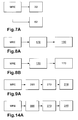
- Reference to figure 8A shows schematically a manual release element (MRE) which operates the clutch lever stop arm 170 which in turn operates the pawl 130 to open the latch.
- MRE manual release element
- Operation of the second embodiment of latch arrangement 110 is similar to the first embodiment in that operation of a manual release element (such as an inside release handle), following failure of the power closure mechanism 138, to disengage the pawl from the latch bolt 116 causes displacement of the stop pin 164 so as to allow anticlockwise rotation of the clutch lever 158.
- This anticlockwise rotation allows for retraction of the drive tooth 150 from the path of the closure abutment 128 upon rotation of the latch bolt 116 to release the striker 114.
- the movement of the stop pin 114 to release the clutch lever 158 to move the power closure mechanism 138 to the escaped state is achieved as follows.
- the pawl When the manual release element is activated by the operator, the pawl is caused to rotate in an anticlockwise direction which disengages the pawl tooth 136 from the closure abutment 128. Since the clutch lever stop arm 170 is mounted for rotation with the pawl 130 about the pawl pivot 132, the clutch lever stop arm 170 is also rotated in an anticlockwise direction which moves the stop pin 164 from the dashed position to the solid line position, as shown in figure 8. Operation of the second embodiment of the latch arrangement 110 is otherwise substantially similar to that of the first embodiment of latch arrangement 10, as described above.
- a third embodiment of latch arrangement indicated generally at 210 is shown with components in common with the first embodiment of latch arrangement 10 numbered 200 greater.
- the power drive lever 240 and closure lever 248 differ from the first two embodiments in that the closure lever spring 251 is attached to power drive lever pivot 242, and not to a separate spring fixture as in the first and second embodiments.
- the latch bolt 216 differs slightly in profile from the first and second embodiments, but is identical in terms of the relative position of the abutments 224, 226 and 228.
- the pawl 280 and the clutch lever stop arm 282 differ from the earlier embodiments, both in their physical features and their mode of operation, as follows.
- the pawl 280 is pivoted about a pawl pivot 232 and defines a pawl tooth 236. Unlike earlier embodiments, the pawl further defines an upper pawl stop 284, and a lower pawl stop 286.
- the clutch lever stop arm 282 has a first arm for engagement with the clutch lever 258 and a second arm which defines an upper aperture 283 for receiving the upper pawl stop 284, a lower aperture 285 for receiving the lower pawl stop 286 and a release detent 288.
- the clutch lever stop arm 282 is pivoted about a pivot 287 and is biased for rotation in the anticlockwise direction by clutch lever stop arm spring 289.
- the latch arrangement 210 includes a release lever 290 pivoted about pivot 294 and rotationally biased by release lever spring 291.
- a release lever stop 293 Arranged at a first end of the pivoted release lever 290 is a release lever stop 293. Under action of the release lever spring 291 the release lever stop is biased towards the clutch lever stop arm 282. In this manner, with the pivoted release lever 290 in the position shown in figure 9, the release lever stop 293 retains the clutch lever stop arm 282 in position by way of its engagement with the release detent 288.
- the power drive lever 240 is driven in an anticlockwise direction so as to engage the closure lever 248 with the bearing surface 260 of the clutch lever 258.
- the bearing of the closure lever 248 against the bearing surface 260 causes the driving tooth 250 to engage the driven abutment 228 in a similar way to earlier embodiments.
- the latch assembly approaches the extreme actuated condition as shown in figure 11.
- the latch bolt 216 has rotated under action of the latch spring to move the pawl tooth 236 to a position proximate the closure abutment 226.
- the latch bolt 216 Upon return of the power closure mechanism 238 to the rest state, the latch bolt 216 will be retained in the fully closed position.
- the operator operates one of the manual release elements (typically an inside door lever or an outside door lever).
- This operates the release lever 290 to move the release lever stop 293 out of engagement with the release detent 288.
- This rotation of the clutch lever stop arm 270 causes the right hand wall of the upper aperture 283 to engage the upper pawl stop 284 which in turn disengages the pawl tooth 236 from the closure abutment 226.
- a manual release element 200 operates the release lever 290 which in turn releases the clutch lever stop arm 270 which releases the pawl 216.
- the latch bolt 216 is therefore able to rotate in an anticlockwise direction from the position shown in figure 12 thereby releasing the striker 214 from the mouth 222 of the latch bolt 216. This releases the striker 214 and leaves the latch assembly in an open condition as shown in figure 11.
- a fourth embodiment of latch arrangement is indicated generally at 310.
- the latch arrangement 310 is similar to the third embodiment of latch arrangement 210.
- the clutch lever stop arm 370 and the release lever 390 are different from those of the third embodiment.
- the clutch lever stop arm 370 has a lower aperture 385 but has no upper aperture. Instead, the clutch lever stop arm 370 has a pawl driver 371 which acts on an upper pawl stop 384.
- the extreme end of the first arm of the clutch lever stop arm 370 has an abutment 373 which acts against a stop 375 to prevent further rotation in the clockwise direction from the position shown in figure 14.
- the release lever 390 Upon release of the latch assembly 310, the release lever 390 is rotated about the release lever pivot 391 in a clockwise direction to move a release stop 393 out of engagement with the clutch lever stop arm 370. This allows the clutch lever stop arm 370 to rotate in an anticlockwise direction which allows the power closure mechanism 338 to retract the dog clutch 348 in order to allow the latch arrangement to open.
- a drive mechanism 410 includes a power drive lever 440 which carries a closure lever 448.
- the power drive lever 440 is pivoted about a power drive lever pivot 442.
- the drive mechanism includes a closure lever spring 454 for biasing rotation of the closure lever 448.
- the closure lever spring 454 is grounded to a latch chassis 412 by a spring fixture 456.
- the stop 458 defines a bearing surface 460 against which the closure lever 448 is rotated in reponse to operation of the power drive lever 440.
- the stop 458 acts in a similar manner to the clutch lever of the previous embodiments with the major difference being that the stop 458 does not move with respect to the power drive lever 440 or the closure lever 448.
- the drive mechanism 410 cooperates with a latch bolt 416 and pawl 430 in a manner similar to the previous embodiments of power closure mechanism in order to drive the latch bolt 416 from the safety position to the closed position.
- the shape of the stop 458 may be other than that shown and still fall within the scope of the invention, provided that the relative relationship of the power drive lever pivot 442, the bearing surface 460 and the closure lever 448 remain constant.
Landscapes
- Lock And Its Accessories (AREA)
Abstract
A latch assembly including a latch bolt (16) for engaging an associated striker (14), the latch bolt having an open position, a safety position and a closed position, which positions correspond to an open condition, a safety condition and closed condition, respectively, in the latch assembly; the latch assembly further comprising: a pawl (30) for releasably retaining the latch bolt in the safety position and the closed position; a power closure mechanism (38) for applying a drive load to the latch bolt to drive the latch bolt from the safety position to the closed position, and a pivotably mounted driving member (48) with a first portion (50): which in use abuts against the latch bolt in response to powered closure; where said powered closure results from movement of the pivot (47) of the driving member combined with abutment of a second portion (51) of the driving member (48) against a bearing surface (60).
Description
- The present invention relates to latches, and in particular, but not exclusively, to vehicle door latches.
- Known vehicle doors include elastomeric door seals secured to the periphery of the door which are compressed when the doors close and the seals come into contact with the periphery of the door aperture. Modem trends in automobile manufacture require high door seal loads to reduce wind generated noise when the vehicle is moving. As a result, increased force must be applied to the door when closed by the operator in order to ensure that the latch mechanism has secured the door shut.
- A consequence of higher seal loads is that the operator is required to apply an increasingly high load to the door in order to ensure the latch secures the door shut. A known solution to this problem is to provide a power closing latch mechanism which drives the latch from a latched safety position, also known as a first safety position, (achieved by the operator gently closing the door), to a fully latched position. In this way, the shut load (the load required to compress the door seals and to drive the latch to the closed condition) is overcome by the power actuator, rather than the operator. However, existing latches have been known to fail during the power close operation rendering impossible the subsequent manual opening of the door latch by the operator.
- Existing solutions to this problem employ fail safe mechanisms which require additional components and which add to the complexity and cost of the design, thereby further increasing the risk of component failure.
- Furthermore, traditional fail safe mechanisms operate by manually disengaging the power drive from the latch mechanism. Typically, this will require the operator to overcome the load generated between the power drive and the latch bolt, which itself is relatively high since this load must overcome the shut load. This can result in unacceptably high manual release loads to open the door under failure conditions.
- In order to over come these high loads known latches employ long lever arms to generate sufficient force to close the latch. This results in larger latches which require a sizeable space envelope in the door and add weight to the door.
- An object of the present invention is to provide an improved form of latch arrangement which at least mitigates the problems outlined above. A further object is to provide a simple and/or easily operable means of disengaging a power closure mechanism for a latch in the event of failure. A further object of the present invention is to provide a drive mechanism for a power closure latch assembly which provides a more space efficient method of driving the latch assembly.
- Thus, according to the present invention there is provided a latch assembly including a latch bolt for engaging an associated striker, the latch bolt having an open position, a safety position and a closed position, which positions correspond to an open condition, a safety condition and closed condition, respectively, in the latch assembly; the latch assembly further comprising: a pawl for releasably retaining the latch bolt in the safety position and the closed position; a power closure mechanism for applying a drive load to the latch bolt to drive the latch bolt from the safety position to the closed position, said power closure mechanism further comprising; a pivotably mounted driving member with a first portion which in use abuts against the latch bolt in response to powered closure; where said powered closure results from movement of the pivot of the driving member combined with abutment of a second portion of the driving member against a bearing surface or support means. Thus, withdrawal of the bearing surface so that in use it cannot abut the driving member provides a simple way of severing the drive path between the power closure means and the driving member in the event of failure etc.. This has the advantage of allowing a user to readily open the latch in the event of an emergency etc..
- Preferably, a clutch stop lever is arranged for escapable engagement with the power closure mechanism. The power closure mechanism may have an actuable state in which the clutch stop lever is engageable with the power closure mechanism, and an escaped state in which the clutch stop lever is not engageable with the power closure mechanism. The power closure mechanism may provide support means for supporting the driving member when the clutch stop lever is engaged with the power closure mechanism, so as to allow the driving member to drive the latch bolt. The driving member may be supported by the support means when the clutch stop lever is disengaged from the power closure mechanism, so as to allow retraction of the driving member from the latch bolt.
- Preferably, the power closure mechanism includes a power drive lever pivoted about an axis of rotation and having a first end which pivotally carries the driving member and a second end for cooperation with a power actuator.
- The power closure mechanism may further includes a block lever pivotally mounted about the axis of rotation, the block lever defining the support means at a first end thereof.
- The interaction of the driving member and the support means may be such that engaged movement of the driving member about the block lever upon movement of the power drive lever causes a gearing between the power drive lever and an output of the driving member.
- The support means may be a cam surface and the gearing is created by the driving member being caused to rotate by its interaction with the cam surface. The support means may also be a set of gear teeth, the driving member defining a co-operating set of gear teeth, the gearing created by the driving member being caused to rotate by interaction of the respective sets of gear teeth.
- The block lever may have a second end which engages the clutch stop lever when the power closure mechanism is in the actuable state.
- Preferably, the driving member has a first arm which defines an output for engaging the pawl and a second arm which carries a drive member spring, the drive member being urged out of engagement with the latch bolt by the drive member spring when the power closure mechanism is in the escaped state.
- The driving member may have a second arm which carries a drive member spring, the drive member being urged out of engagement with the latch bolt by the drive member spring when the power closure mechanism is in the escaped state.
- Preferably, the clutch stop lever is rotatable with the pawl.
- The drive path between a power actuator and the driving member is preferably carried by the power closure mechanism. The clutch stop lever is preferably remote from the drive path.
- According to a second aspect of the present invention there is provided A latch assembly including a latch bolt for engaging an associated striker, the latch bolt having an open position, a safety position and a closed position, which positions correspond to an open condition, a safety condition and closed condition, respectively, in the latch assembly, the latch assembly further including a pawl for releasably retaining the latch bolt in the safety position and the closed position, a power closure mechanism having a retractable driving member for applying a drive load to the latch bolt to drive the latch bolt from the safety position to the closed position, in which a direction of retraction of the driving member from the latch bolt is substantially parallel to the direction of the drive load, retraction of the driving member permitting opening of the latch.
- The optional features recited above in respect of the first mentioned aspect of the invention also apply to the second aspect.
- According to a further aspect of the present invention there is provided a drive mechanism for a power closure latch assembly, including a drive lever driveable by a power drive and which carries a rotatable driving member, the driving member having an output for driving a latch bolt, the assembly further including a stop for co-operating, in use, with the driving member, such that engaged movement of the driving member about the stop upon movement of the drive lever causes rotation of the output relative to the drive lever so as to drive the latch bolt.
- The invention will now be described by way of example only, and with reference to the following drawings, in which:-
- Figure 1 is a schematic representation of a first embodiment of a latch assembly according to the present invention, with the latch assembly in the open condition,
- Figure 2 is a schematic view of the latch assembly of figure 1 with the latch bolt in the safety position,
- Figure 3 is a schematic view of the latch assembly of figure 2, with the power drive lever actuated to engage the closure lever with the latch bolt,
- Figure 4 is a schematic view of the latch assembly of figure 3 with the power drive lever further actuated to engage the closure lever with the clutch lever and the latch bolt,
- Figure 5 is a schematic view of the latch assembly of figure 4 with the power drive lever further actuated to engage the clutch lever with the lever clutch lever stop,
- Figure 6 is a schematic view of the latch assembly of figure 5 with the power drive lever further actuated leaving the latch bolt in the closed position,
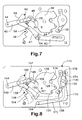
- Figure 7 shows the latch assembly of figure 1 with the power drive lever mid-way to being returned to its rest position and the latch bolt released by the pawl during attempted opening of the latch,
- Figure 8 is a schematic view of a second embodiment of latch assembly according to the present invention with the latch assembly shown in solid lines in a condition corresponding to that shown in figure 7,
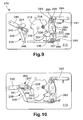
- Figure 9 is a schematic view of a third embodiment of latch assembly according to the present invention with the latch bolt in the safety position,
- Figure 10 is a schematic view of the latch assembly of figure 9 with the power drive lever actuated to engage the closure lever with the latch bolt,
- Figure 11 is a schematic view of the latch assembly of figure 10, with the power drive lever further actuated to move the latch bolt to the closed position,
- Figure 12 is a schematic view of the latch assembly of figure 11 with the pawl disengaged from the latch bolt so as to open the latch assembly,
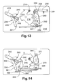
- Figure 13 is a schematic view of the latch assembly of figure 12 with the power drive lever in the rest position and the latch bolt in the open position,
- Figure 14 is a schematic view of a fourth embodiment of latch assembly in accordance with the present invention with the latch bolt in the safety position,
- Figure 15 is a schematic view of a drive mechanism according to the present invention.
- In figure 1 a latch indicated generally at 8 includes a
latch assembly 10 and an associatedstriker 14. Thelatch assembly 10 is mounted on a latch chassis shown schematically at 12. Typically, thelatch chassis 12 would be mounted in the door of a vehicle, which is not shown for clarity. Thestriker 14 is typically mounted on the vehicle body (also not shown for clarity) and is engaged in use by thelatch assembly 10 to close the door, as will be described further shortly. - The
latch assembly 10 includes alatch bolt 16 mounted for rotation onlatch bolt pivot 18. Thelatch bolt 16 is biased to rotate in an anticlockwise direction by alatch spring 17, and is prevented from rotating past the position shown in figure 1 bylatch bolt stop 20. Thelatch bolt 16 has amouth 22 for receiving the striker, asafety abutment 24 and aclosure abutment 26. The latch bolt further includes adrive abutment 28, the purpose of which will be discussed in further detail shortly. - The
latch assembly 10 haspawl 30 which is mounted for rotation on apawl pivot 32 and is rotationally biased in the clockwise direction by thelatch spring 17. Apawl stop 34 prevents clockwise rotation of thepawl 30 beyond its position shown in figure 1. Thepawl 30 defines apawl tooth 36 for engagement with thesafety abutment 24 andclosure abutment 26 of thelatch bolt 16, as will be described further shortly. - The
latch assembly 10 includes a power closure mechanism indicated generally at 38. The power closure mechanism comprises apower drive lever 40 which is rotatably mounted on powerdrive lever pivot 42. Thepower drive lever 40 has afirst end 44 which is driveable by a power actuator (not shown) such as an electric motor, or hydraulic or pneumatic actuator. The power actuator drives thepower drive lever 40 by way of a bowden cable or similar known method. Thepower drive lever 40 has asecond end 46 which supports, bypivot 47, an L-shaped driving member in the form ofclosure lever 48. Theclosure lever 48 has a first arm defining an output in the form of adrive tooth 50 and a second arm defining apin 52 for retaining the first end of aclosure lever spring 54. The second end of theclosure lever spring 54 is fixed to thelatch chassis 12 by way of aspring fixture 56. The second arm also defines anengagement surface 51 the function of which will be described below. - In addition to the power drive lever 40 a block lever in the form of
clutch lever 58 is also provided for rotation about the powerdrive lever pivot 42. Theclutch lever 58 has afirst arm 59 defining a support means in the form of bearingsurface 60 for engagement, in use, with theengagement surface 51 of theclosure lever 48, as will be described further shortly. Theclutch lever 58 has asecond arm 61 provided for engagement with aclutch lever stop 62. Theclutch lever stop 62 engages theclutch lever 58 by way of astop pin 64. Theclutch lever stop 62 is moveable between a stop position shown in figures 1 to 6 and a release position shown in figure 7. Theclutch lever stop 62 is moveable between these two positions by sliding over slide pins 63. In its stop position (figures 1 to 6) the stop pins 64 prevents anticlockwise rotation of theclutch lever 58 beyond the position shown in figures 5 and 6. However, once theclutch lever stop 62 has been moved to the release position as shown in figure 7, thesecond arm 61 of theclutch lever 58 is allowed to rotate in an anticlockwise direction past thestop pin 64. The purpose of the engagement and disengagement of the clutch lever stop 62 with theclutch lever 58 will be explained in further detail shortly. - In figure 1 the
latch assembly 10 is shown in the open condition, with the latch bolt in the open position. It will be appreciated that thestriker 14 is close to thelatch bolt 16, which indicates that the associated door is approaching the car body, although the door is not yet closed. - In use, the
latch arrangement 8 operates in the following manner. As the operator closes the door of the vehicle, the latch assembly 10 (which is mounted in the vehicle door) moves towards the striker 14 (situated in the car body). With thelatch assembly 10 in the open condition shown in figure 1, the operator has moved the car door sufficiently far that the mouth of the striker is in close proximity to thestriker 14. With a further push of the door towards the car body, themouth 22 of thelatch bolt 16 will receive thestriker 14 which will cause thelatch bolt 16 to rotate in a clockwise direction. This rotation of thelatch bolt 16 causes pawltooth 36 to ride up the periphery of thelatch bolt 16 to a position proximate thesafety abutment 24. Under bias of thelatch spring 17 thepawl 30 rotates in a clockwise direction so that thepawl tooth 36 engages thesafety abutment 24 as shown in figure 2. - In figure 2, the
latch bolt 16 is retained by thepawl 30 by way of the engagement of thepawl tooth 36 with thesafety abutment 24. Thelatch arrangement 10 is therefore in the safety condition, with thelatch bolt 60 in its safety position. The car door is therefore partially closed; thestriker 14 is retained by thelatch bolt 16, but thelatch bolt 16 has not yet moved to the closed position. It will be appreciated that thepower closure mechanism 38 has not yet been actuated, and thelatch arrangement 10 has achieved the safety condition by conventional manual closure of the door by an operator. - With the
latch assembly 10 in the safety condition, as shown in figure 2, the operator does not need to further operate the door in order for the door to fully close. Full closure of the door is achieved by thepower closure mechanism 38 as follows. - In figure 2 the
power closure mechanism 38 is in its rest position. The movement of thelatch assembly 10 to the safety condition shown in figure 2 is detected by a sensor of known type and which is not shown for clarity. The sensor, typically in the form of a microswitch or optical sensor relays a signal to a central processing unit (CPU), also not shown, to instruct that the latch bolt is in the first safety position. Upon receipt of the signal the CPU instructs the power actuator (not shown for clarity) to drive thepower closure mechanism 38 to move the latch assembly through the positions shown in figures 3, 4, 5 to its closed condition (see figure 6). Thepower closure mechanism 38 operates in the following manner. - The
first end 44 of thepower drive lever 40 is driven by the power actuator to rotate thepower drive lever 40 in an anticlockwise direction. This causes thesecond end 46 of thepower drive lever 40 to rotate theclosure lever 48 to a position where thedrive tooth 50 picks up thedrive abutment 28, as shown in figure 3. The pick up is ensured by theclosure lever spring 54 which biases movement of theclosure lever 48 so as to present thedrive tooth 50 in a position proximate the drivenabutment 28. Further rotation of thepower drive lever 40 causes theengagement surface 51 of theclosure lever 48 to engage the bearingsurface 60 of theclutch lever 58 as shown in figure 4. - Continued rotation of the
power drive lever 40 drives the closure lever in direction A as shown in figure 4. A load is thereby transferred from theengagement surface 51 of theclosure lever 50 to theclutch lever 58 via the bearingsurface 60. This load exerts a force in the direction B in figure 4 which causes theclutch lever 58 to rotate about theclutch lever pivot 42 in an anticlockwise direction to the position shown in figure 5. This rotation causes the second arm of theclutch lever 58 to come into contact with thestop pin 64 of theclutch lever stop 62, thereby preventing further anticlockwise rotation of theclutch lever 58. - Upon further driving of the
power drive lever 40 in the anticlockwise direction, thepower closure mechanism 38 moves from the position shown in figure 5 to the position shown in figure 6. This stage of power closure occurs as follows. - Anticlockwise rotation of the
power drive lever 40 beyond the position shown in figure 5 creates a drive path between thepower drive lever 40 and thelatch bolt 18 via theclosure lever 48. Thepower drive lever 40 exerts a load on theclosure lever 48 in the direction annotated C in figure 5. Since anticlockwise rotation of theclutch lever 58 is prevented by its engagement with thestop pin 64 of theclutch lever stop 62, further driving of thepower drive lever 40 results in a load being applied to thedrive abutment 28 by thedrive tooth 50 in the direction annotated D in figure 5. Since theclutch lever 58 is prevented from rotating via thestop pin 64, and theclosure lever 48 is prevented from rotating in a clockwise direction by the bearingsurface 60 of theclutch lever 58, theclosure lever 48 is caused to rotate in an anticlockwise direction which causes the load D to drive the latch bolt in a clockwise direction from the position shown in figure 5 to the closed position shown in figure 6. In this way, the driving of thepower drive lever 40 causes theengagement surface 51 of theclosure lever 48 to be driven about the bearingsurface 60. - This in turn causes the
drive tooth 50 to move in an anticlockwise direction drives thelatch bolt 16 in a clockwise direction via the drivenabutment 28. - The action of driving the closure lever 48 (via its engagement surface) about the bearing
surface 60 causes additional gearing between thepower drive lever 40 and thedrive tooth 50 by virtue of the rotation generated in theclosure lever 48 as a result of its rotation about thesecond end 46 of thepower drive lever 40. Thus, the comparison between figures 5 and 6 show that thepower drive lever 40 has rotated 11 degrees anticlockwise when moving from the figure 5 to the figure 6 position whereas thedrive tooth 50 has rotated 35 degrees anticlockwise when moving from the figure 5 position to the figure 6 position. This 35 degree anticlockwise rotation comprises 11 degrees of anticlockwise rotation by virtue of the fact that theclosure lever 48 is mounted on thepower drive lever 40 which itself has rotated 11 degrees anticlockwise, but also because theclosure lever 48 rotates 25 degrees anticlockwise relative to thepower drive lever 40. - It is conceivable within the scope of the invention that the gearing may be generated by way of inter-engaging sets of gear teeth on each of the bearing surface and dog clutch, respectively.
- The advantage of this gearing is that the distance between the power
drive lever pivot 42 and thelatch bolt pivot 18 can be reduced since the movement required in thedrive tooth 50 to drive thelatch bolt 16 can be achieved using a shorterpower drive lever 40. If theclosure lever 48 was not caused to rotate about the bearingsurface 60 ofclutch stop 58, a far longerpower drive lever 40 would be required in order to achieve the required movement in thedrive tooth 50. - As the driving of the
power drive lever 40 continues towards the position shown in figure 6, thelatch bolt 16 is rotated sufficiently far in a clockwise direction to allow thepawl tooth 36 to engage theclosure abutment 26. The latch assembly is then in a closed condition with thestriker 14 retained within thelatch bolt mouth 22. Thepower closure mechanism 38 is then powered to return to its rest state shown in figures 1 and 2. Alternatively,spring 54 may be powerful enough to return thepower closure mechanism 38 to the rest position. - Should the operator subsequently wish to open the door, the
latch assembly 10 is simply operated in a conventional manner (via a door handle for example) to disengage thepawl tooth 30 from theclosure abutment 26. This allows anticlockwise rotation of thelatch bolt 16 to release the striker from thelatch bolt mouth 22, thereby opening the door. Subsequent closure of the door is as described above with reference to figures 1 to 6. - Described above is the normal mode of operation of the
latch assembly 10. In this manner the associated door may be opened and closed repeatedly. Throughout the operation of the latch assembly described above thepower closure mechanism 38 has remained in an actuable state, i.e. it is moveable between its rest position (figure 1), its safety position (figure 5) and its closed position (figure 6) repeatedly to allow opening and closing of the door. Theclutch lever stop 62 has remained in its stop position, allowing engagement of thestop pin 64 with theclutch lever 58 when the latch assembly is driven to its closed condition. Such engagement has in turn ensured the bearingsurface 60 is able to support theclosure lever 48 when thelatch bolt 16 is moved to its closed position. - However, there may be occasions where the
power closure mechanism 38 fails part way through the closing sequence, for example at the figure 5 position with theclosure lever 48 obstructing movement of thelatch bolt 16, it is clearly necessary to provide the latch assembly with a manual override to allow the door to be opened. Such a contingency is provided for as follows. - With reference to figures 7 and 7A, under operation of one of the manual door release elements (MRE) for example an inside door handle or outside door handle, the
pawl tooth 36 has disengaged from theclosure abutment 28. Such operation is shown schematically in figure 7A in which a manual release element (MRE) acts on thepawl 30 to release thelatch bolt 16 and simultaneously operates on theclutch lever stop 62 to allow thepower closure mechanism 38 to move to the escaped state. Additionally, and importantly, operation of the manual release element (MRE) has also moved the clutch lever stop 62 from its stop position shown in figures 1 to 6, to its release position. This movement has caused thestop pin 64 to release theclutch lever 58 allowing it to rotate in an anticlockwise direction from its position shown in figures 1 to 6 to the position shown in figure 7. In turn, this movement has freed theclosure lever 48 from the bearingsurface 60 of theclutch lever 58 allowing thelatch bolt 16 to drive theclosure lever 48 in a clockwise direction under action of thelatch spring 17. This drives thedrive tooth 50 out of the way of thedrive abutment 28 and thelatch bolt 16 continues to rotate in the anticlockwise direction. Thepower closure mechanism 38 has escaped theclutch lever stop 62 and thedrive abutment 28 and has therefore moved from the actuable state described above to an escaped state. With thepower closure mechanism 38 in this escaped state, thelatch bolt 16 is permitted to release thestriker 14, thereby opening the door. - Returning briefly to figure 5, it will be appreciated that the load E reacted by the
stop pin 64 under action of thesecond arm 61 of theclutch lever 58 is significantly less than the load D applied by thedrive tooth 50 to theclosure abutment 28. The advantage of this is that the manual effort required to disengage thestop pin 64 from theclutch lever 58 is substantially less than that which would be required to disengage thedrive tooth 50 from theclosure abutment 28. Even under power closure failure conditions, the operator does not experience any significant difference in the operation of the manual release element to open the door. This is because the point of escapement of thepower closure mechanism 38 is between theclutch stop lever 62 and theclutch lever 58 and as such is not within the drive path between the power actuator and the latch bolt. This allows thedrive tooth 50 to retract from thedrive abutment 28 in the same plane as the load D. Thus, the friction between thedrive tooth 50 and thedrive abutment 28 need not be overcome to open thelatch bolt 16. - In figure 8 a second embodiment of latch arrangement is indicated generally at 110, with components in common with the first embodiment of the
latch arrangement 10 numbered 100 greater. The difference between the first and second embodiments of latch arrangement is the replacement of the clutch lever stop 62 of the first embodiment with the clutchlever stop arm 170 in the second embodiment. The clutchlever stop arm 170 is pivoted for rotation about thepawl pivot 132 and has an L-shapedfirst arm 172 and a shortersecond arm 174. Thesecond arm 172 defines astop pin 164 which is provided to engage and disengage theclutch lever 158 to change the state of thepower closure mechanism 138 between the actuable state and the escaped state in a similar fashion to thestop pin 64 in the first embodiment. The shortersecond arm 174 of the clutchlever stop arm 170 defines apawl abutment 176. Thepawl abutment 176 acts on the pawl following operation of a manual release element to disengage thepawl tooth 136 from theclosure abutment 124 to allow thelatch bolt 116 to release thestriker 114. Reference to figure 8A shows schematically a manual release element (MRE) which operates the clutchlever stop arm 170 which in turn operates thepawl 130 to open the latch. - It will be appreciated that within the scope of the invention it is possible for the manual release element to act on the pawl which in turn operates the clutch
lever stop arm 170. This is shown schematically in figure 8B. - Operation of the second embodiment of
latch arrangement 110 is similar to the first embodiment in that operation of a manual release element (such as an inside release handle), following failure of thepower closure mechanism 138, to disengage the pawl from thelatch bolt 116 causes displacement of thestop pin 164 so as to allow anticlockwise rotation of theclutch lever 158. This anticlockwise rotation allows for retraction of thedrive tooth 150 from the path of theclosure abutment 128 upon rotation of thelatch bolt 116 to release thestriker 114. The movement of thestop pin 114 to release theclutch lever 158 to move thepower closure mechanism 138 to the escaped state is achieved as follows. When the manual release element is activated by the operator, the pawl is caused to rotate in an anticlockwise direction which disengages thepawl tooth 136 from theclosure abutment 128. Since the clutchlever stop arm 170 is mounted for rotation with thepawl 130 about thepawl pivot 132, the clutchlever stop arm 170 is also rotated in an anticlockwise direction which moves thestop pin 164 from the dashed position to the solid line position, as shown in figure 8. Operation of the second embodiment of thelatch arrangement 110 is otherwise substantially similar to that of the first embodiment oflatch arrangement 10, as described above. - In figures 9 to 13, a third embodiment of latch arrangement indicated generally at 210 is shown with components in common with the first embodiment of
latch arrangement 10 numbered 200 greater. - The
power drive lever 240 andclosure lever 248 differ from the first two embodiments in that theclosure lever spring 251 is attached to powerdrive lever pivot 242, and not to a separate spring fixture as in the first and second embodiments. Thelatch bolt 216 differs slightly in profile from the first and second embodiments, but is identical in terms of the relative position of theabutments pawl 280 and the clutchlever stop arm 282 differ from the earlier embodiments, both in their physical features and their mode of operation, as follows. - The
pawl 280 is pivoted about apawl pivot 232 and defines apawl tooth 236. Unlike earlier embodiments, the pawl further defines anupper pawl stop 284, and alower pawl stop 286. The clutchlever stop arm 282 has a first arm for engagement with theclutch lever 258 and a second arm which defines anupper aperture 283 for receiving theupper pawl stop 284, alower aperture 285 for receiving thelower pawl stop 286 and arelease detent 288. The clutchlever stop arm 282 is pivoted about apivot 287 and is biased for rotation in the anticlockwise direction by clutch leverstop arm spring 289. Thelatch arrangement 210 includes arelease lever 290 pivoted aboutpivot 294 and rotationally biased byrelease lever spring 291. Arranged at a first end of the pivotedrelease lever 290 is arelease lever stop 293. Under action of therelease lever spring 291 the release lever stop is biased towards the clutchlever stop arm 282. In this manner, with the pivotedrelease lever 290 in the position shown in figure 9, therelease lever stop 293 retains the clutchlever stop arm 282 in position by way of its engagement with therelease detent 288. - Operation of the
latch assembly 210 is as follows. In figure 9 the latch assembly is in the safety condition, with thepower closure mechanism 238 in its rest state. With the latch assembly in this condition, the clutchlever stop arm 282 is biased in an anticlockwise direction by the clutch leverstop arm spring 289. This biased rotation causes the right hand wall of theupper aperture 283 and the left hand wall of thelower aperture 285 to be urged against theupper pawl stop 284 andlower pawl stop 286, respectively. This causes therelease abutment 288 to engage therelease lever stop 293. Therelease lever stop 293 is prevented from disengaging therelease abutment 288 by the action of therelease lever spring 291. - In order to fully close the latch assembly, the
power drive lever 240 is driven in an anticlockwise direction so as to engage theclosure lever 248 with the bearingsurface 260 of theclutch lever 258. The bearing of theclosure lever 248 against the bearingsurface 260 causes the drivingtooth 250 to engage the drivenabutment 228 in a similar way to earlier embodiments. - As the
power drive lever 240 is driven further, the latch assembly approaches the extreme actuated condition as shown in figure 11. In this position, thelatch bolt 216 has rotated under action of the latch spring to move thepawl tooth 236 to a position proximate theclosure abutment 226. Upon return of thepower closure mechanism 238 to the rest state, thelatch bolt 216 will be retained in the fully closed position. - In order to subsequently open the door, the operator operates one of the manual release elements (typically an inside door lever or an outside door lever). This operates the
release lever 290 to move the release lever stop 293 out of engagement with therelease detent 288. This allows the clutchlever stop arm 270 to rotate in an anticlockwise direction under the clutch leverstop arm spring 289. This rotation of the clutchlever stop arm 270 causes the right hand wall of theupper aperture 283 to engage the upper pawl stop 284 which in turn disengages thepawl tooth 236 from theclosure abutment 226. This is shown schematically in figure 9A, in which a manual release element 200 operates therelease lever 290 which in turn releases the clutchlever stop arm 270 which releases thepawl 216. Thelatch bolt 216 is therefore able to rotate in an anticlockwise direction from the position shown in figure 12 thereby releasing thestriker 214 from the mouth 222 of thelatch bolt 216. This releases thestriker 214 and leaves the latch assembly in an open condition as shown in figure 11. - In figure 14, a fourth embodiment of latch arrangement is indicated generally at 310. The latch arrangement 310 is similar to the third embodiment of
latch arrangement 210. However, the clutchlever stop arm 370 and therelease lever 390 are different from those of the third embodiment. - The clutch
lever stop arm 370 has alower aperture 385 but has no upper aperture. Instead, the clutchlever stop arm 370 has apawl driver 371 which acts on anupper pawl stop 384. - The extreme end of the first arm of the clutch
lever stop arm 370 has anabutment 373 which acts against astop 375 to prevent further rotation in the clockwise direction from the position shown in figure 14. - Upon release of the latch assembly 310, the
release lever 390 is rotated about therelease lever pivot 391 in a clockwise direction to move arelease stop 393 out of engagement with the clutchlever stop arm 370. This allows the clutchlever stop arm 370 to rotate in an anticlockwise direction which allows thepower closure mechanism 338 to retract the dog clutch 348 in order to allow the latch arrangement to open. - This is shown schematically in figure 14A in which a manual release element 300 acts on the
release lever 390 to release the clutchlever stop arm 370 which in turn releases thepawl 316. - It will be appreciated that the operation of the power closure mechanism in each of the second, third and fourth embodiment operate in substantially the same manner as that of the first embodiment.
- In figure 15 a
drive mechanism 410 includes apower drive lever 440 which carries aclosure lever 448. Thepower drive lever 440 is pivoted about a powerdrive lever pivot 442. The drive mechanism includes aclosure lever spring 454 for biasing rotation of theclosure lever 448. Theclosure lever spring 454 is grounded to alatch chassis 412 by aspring fixture 456. - The major difference between the
drive mechanism 410 and the power closure mechanisms of the previous embodiments, is the provision of astop 458 which is grounded to thelatch chassis 412 and is immovable with respect to the powerdrive lever pivot 442. Thestop 458 defines abearing surface 460 against which theclosure lever 448 is rotated in reponse to operation of thepower drive lever 440. Thestop 458 acts in a similar manner to the clutch lever of the previous embodiments with the major difference being that thestop 458 does not move with respect to thepower drive lever 440 or theclosure lever 448. - The
drive mechanism 410 cooperates with alatch bolt 416 andpawl 430 in a manner similar to the previous embodiments of power closure mechanism in order to drive thelatch bolt 416 from the safety position to the closed position. It will be appreciated that the shape of thestop 458 may be other than that shown and still fall within the scope of the invention, provided that the relative relationship of the powerdrive lever pivot 442, the bearingsurface 460 and theclosure lever 448 remain constant.
Claims (15)
- A latch assembly including a latch bolt (16) for engaging an associated striker (14), the latch bolt having an open position, a safety position and a closed position, which positions correspond to an open condition, a safety condition and closed condition, respectively, in the latch assembly; the latch assembly further comprising:a pawl (30) for releasably retaining the latch bolt in the safety position and the closed position;a power closure mechanism (38) for applying a drive load to the latch bolt to drive the latch bolt from the safety position to the closed position, said power closure mechanism further comprising;a pivotably mounted driving member (48) with a first portion (50) which in use abuts against the latch bolt in response to powered closure; where said powered closure results from movement of the pivot (47) of the driving member combined with abutment of a second portion (51) of the driving member (48) against a bearing surface or support means (60).
- The latch assembly of claim 1 where the pivot (47) lies between the first portion (50) and the second portion (51).
- The latch assembly of any preceding claim wherein the power closure mechanism (38) includes a pivotable power drive lever (40) having a first end which pivotally (47) carries the driving member (48) and a second end for cooperation with a power actuator.
- The latch assembly of any preceding claim wherein the power closure mechanism further includes a pivotally mounted block lever (58), the block lever defining the support means (60) at a first end thereof.
- The latch assembly of claim 4 wherein the interaction of the driving member (48) and the support means (60) is such that engaged movement of the driving member about the block lever (58) upon movement of the power drive lever (40) causes a gearing between the power drive lever and an output of the driving member.
- The latch assembly of any preceding claim wherein the support means (60) is a cam surface and the gearing is created by the driving member (48) being caused to rotate by its interaction with the cam surface.
- The latch assembly of any of claims 1 to 5 wherein the support means (60) is a set of gear teeth, the driving member defining a co-operating set of gear teeth, the gearing created by the driving member (48) being caused to rotate by interaction of the respective sets of gear teeth.
- The latch assembly of any preceding claim wherein the driving member (48) has a first arm which defines the first portion (50) for engaging the latch bolt (16) and a second arm which carries a drive member spring (54), the drive member being urged out of engagement with the latch bolt by the drive member spring when the power closure mechanism is in an escaped state.
- A latch arrangement including the latch assembly of any preceding claim and a power actuator, in which a drive path between the power actuator and the driving member (48) is carried by the power closure mechanism (38).
- A latch assembly according to any preceding where in use the drive path between the power closure mechanism (38) and the driving member (48) is severed by withdrawal of the bearing surface (60) from the proximity of driving member (48).
- The latch assembly of any preceding claim wherein a clutch stop lever (62) is arranged for escapable engagement with the power closure mechanism (38),
the power closure mechanism having an actuable state in which the clutch stop lever is engageable with the power closure mechanism, and an escaped state in which the clutch stop lever is not engageable with the power closure mechanism,
the power closure mechanism providing support means (60) for supporting the driving member when the clutch stop lever is engaged with the power closure mechanism, so as to allow the driving member to drive the latch bolt (16),
the driving member being unsupported by the support means when the clutch stop lever is disengaged from the power closure mechanism, so as to allow retraction of the driving member from the latch bolt. - The latch assembly of claim 11 wherein the block lever (58), defines the support means (60) at a second end thereof.
- The latch assembly of claim 11 or 12 wherein the first end of the block lever (58) engages the clutch stop lever (62) when the power closure mechanism (38) is in the actuable state.
- The latch assembly of any of Claims 11 to 13 wherein the clutch stop lever (62) is rotatable with the pawl (30).
- The latch arrangement of claim 14 wherein the clutch stop lever (62) is remote from the drive path.
Applications Claiming Priority (1)
| Application Number | Priority Date | Filing Date | Title |
|---|---|---|---|
| GB0506023A GB0506023D0 (en) | 2005-03-24 | 2005-03-24 | Power closure latch assembly |
Publications (1)
| Publication Number | Publication Date |
|---|---|
| EP1710377A2 true EP1710377A2 (en) | 2006-10-11 |
Family
ID=34531782
Family Applications (1)
| Application Number | Title | Priority Date | Filing Date |
|---|---|---|---|
| EP20060251595 Withdrawn EP1710377A2 (en) | 2005-03-24 | 2006-03-24 | Power closure latch assembly |
Country Status (4)
| Country | Link |
|---|---|
| US (1) | US20060226661A1 (en) |
| EP (1) | EP1710377A2 (en) |
| CN (1) | CN1873176A (en) |
| GB (1) | GB0506023D0 (en) |
Cited By (5)
| Publication number | Priority date | Publication date | Assignee | Title |
|---|---|---|---|---|
| DE202006017231U1 (en) * | 2006-11-09 | 2008-03-20 | BROSE SCHLIEßSYSTEME GMBH & CO. KG | Motor vehicle lock |
| GB2446804A (en) * | 2007-02-23 | 2008-08-27 | Meritor Technology Inc | Releasing a load support mechanism |
| DE102008048773A1 (en) * | 2008-09-24 | 2010-03-25 | Kiekert Ag | Motor vehicle door lock |
| DE102008048772A1 (en) * | 2008-09-24 | 2010-03-25 | Kiekert Ag | Motor vehicle door lock |
| JP2018135732A (en) * | 2017-02-23 | 2018-08-30 | アイシン精機株式会社 | Control apparatus of opening/closing body for vehicle |
Families Citing this family (25)
| Publication number | Priority date | Publication date | Assignee | Title |
|---|---|---|---|---|
| CN101680243B (en) * | 2007-05-30 | 2013-05-01 | 胡夫休尔斯贝克及福尔斯特公司 | Closure for vehicles |
| CA2788576A1 (en) * | 2010-02-05 | 2011-08-11 | Magna Closures S.P.A. | Vehicular latch with double pawl arrangement |
| CN103132823B (en) * | 2011-11-26 | 2015-09-30 | 张国网 | A kind of automobile right front door lock assembly |
| CN103132821B (en) * | 2011-11-26 | 2014-12-17 | 张国网 | Automobile right front door lock |
| CN103132824B (en) * | 2011-11-26 | 2014-12-17 | 张国网 | Automobile left front door lock |
| EP2602184B1 (en) * | 2011-12-09 | 2018-03-07 | Safran Landing Systems | A latching box with an unlocking actuator having a cylindrical cam |
| BR112014021230A2 (en) * | 2012-03-01 | 2019-09-24 | Magna Closures Inc | latch for a locking panel for a vehicle |
| KR101372022B1 (en) * | 2012-08-24 | 2014-03-07 | 기아자동차주식회사 | 2 step open hood latch apparatus for vehicle |
| KR101382913B1 (en) * | 2012-09-05 | 2014-04-08 | 기아자동차주식회사 | 2 Step link hood latch apparatus for vehicle |
| US9920555B2 (en) * | 2013-01-18 | 2018-03-20 | Kiekert Ag | Lock for a motor vehicle |
| US20160319571A1 (en) * | 2014-03-12 | 2016-11-03 | August Home Inc. | Intelligent door lock system with optical sensor |
| US20140319848A1 (en) * | 2013-04-29 | 2014-10-30 | GM Global Technology Operations LLC | Latch assembly release effort control, and method thereof |
| GB201408075D0 (en) * | 2014-05-07 | 2014-06-18 | Chevalier John P | Closure and latching mechanisms |
| KR101560979B1 (en) * | 2014-05-30 | 2015-10-15 | 평화정공 주식회사 | Hood latch having dual unlocking function |
| US20160168883A1 (en) * | 2014-12-15 | 2016-06-16 | GM Global Technology Operations LLC | Double pull action vehicle hood latch |
| US10941592B2 (en) * | 2015-05-21 | 2021-03-09 | Magna Closures Inc. | Latch with double actuation and method of construction thereof |
| FR3038643A1 (en) * | 2015-07-06 | 2017-01-13 | Inteva Products Llc | |
| KR101836620B1 (en) * | 2016-04-21 | 2018-03-08 | 현대자동차주식회사 | Cinching latch assembly for vehicle |
| DE102017209376A1 (en) * | 2016-06-07 | 2017-12-07 | Magna Closures Inc. | Vehicle lock latch assembly with double pawl latch mechanism |
| DE102016011162A1 (en) * | 2016-09-16 | 2018-03-22 | Magna BÖCO GmbH | Locking device for a vehicle door and method |
| CN107605284B (en) * | 2017-10-31 | 2022-09-02 | 无锡瑞林智能科技有限公司 | Self-suction side door lock unlocking clutch mechanism |
| US11118381B2 (en) * | 2018-03-07 | 2021-09-14 | GM Global Technology Operations LLC | Dual-pull latch assemblies for compartment closure assemblies of motor vehicles |
| CN113700399B (en) | 2018-12-19 | 2023-05-09 | 麦格纳覆盖件有限公司 | Actuator and door actuation system for a door of a vehicle |
| CN111794611B (en) | 2019-04-02 | 2022-04-05 | 麦格纳博科股份有限公司 | Power actuator with cam-driven dual cable actuation mechanism for use with a vehicle closure latch assembly |
| CN113739466B (en) * | 2021-08-30 | 2022-11-22 | 江苏凯德电控科技有限公司 | Self-locking pop-up switch device, automatic ice making device and refrigerator |
-
2005
- 2005-03-24 GB GB0506023A patent/GB0506023D0/en not_active Ceased
-
2006
- 2006-03-24 CN CNA2006100820631A patent/CN1873176A/en active Pending
- 2006-03-24 US US11/389,520 patent/US20060226661A1/en not_active Abandoned
- 2006-03-24 EP EP20060251595 patent/EP1710377A2/en not_active Withdrawn
Cited By (7)
| Publication number | Priority date | Publication date | Assignee | Title |
|---|---|---|---|---|
| DE202006017231U1 (en) * | 2006-11-09 | 2008-03-20 | BROSE SCHLIEßSYSTEME GMBH & CO. KG | Motor vehicle lock |
| GB2446804A (en) * | 2007-02-23 | 2008-08-27 | Meritor Technology Inc | Releasing a load support mechanism |
| GB2446804B (en) * | 2007-02-23 | 2011-07-13 | Meritor Technology Inc | Latch Mechanism |
| US8146964B2 (en) | 2007-02-23 | 2012-04-03 | Body Systems Usa, Llc | Support mechanism and a latch mechanism |
| DE102008048773A1 (en) * | 2008-09-24 | 2010-03-25 | Kiekert Ag | Motor vehicle door lock |
| DE102008048772A1 (en) * | 2008-09-24 | 2010-03-25 | Kiekert Ag | Motor vehicle door lock |
| JP2018135732A (en) * | 2017-02-23 | 2018-08-30 | アイシン精機株式会社 | Control apparatus of opening/closing body for vehicle |
Also Published As
| Publication number | Publication date |
|---|---|
| US20060226661A1 (en) | 2006-10-12 |
| GB0506023D0 (en) | 2005-04-27 |
| CN1873176A (en) | 2006-12-06 |
Similar Documents
| Publication | Publication Date | Title |
|---|---|---|
| EP1710377A2 (en) | Power closure latch assembly | |
| US9068379B2 (en) | Vehicle door closer device | |
| EP1953317B1 (en) | A motor vehicle having a double latch assembly | |
| US7125057B2 (en) | Lock mechanism | |
| US6676190B2 (en) | Headliner mounted power liftgate drive mechanism | |
| US20120175896A1 (en) | Vehicle door latch | |
| US7762594B2 (en) | Uni-directional cinching latch assembly and method of operating a cinching latch assembly | |
| KR20100123658A (en) | Vehicle lock | |
| US20050212302A1 (en) | Latch | |
| KR102165338B1 (en) | Lock for a flap or door | |
| US20090243309A1 (en) | Door latch device in a motor vehicle | |
| GB2374381A (en) | Vehicle door latch with powered closure | |
| US20080073917A1 (en) | Dual output jackscrew cinching latch | |
| JP5801480B2 (en) | Electric lock type outside swing door | |
| US20210010304A1 (en) | Motor vehicle lock | |
| EP1176273B1 (en) | Latch arrangement | |
| CN110748251B (en) | Lock override for a latch assembly | |
| WO2000049252A1 (en) | Power door latch assembly | |
| WO2011071914A2 (en) | Vehicle door latch | |
| JP5107170B2 (en) | Door latch device | |
| CN113802931A (en) | Electric locking mechanism for doors and windows comprising a mechanical emergency function | |
| GB2376501A (en) | Vehicle door latch with powered closure | |
| JP2016008408A (en) | Vehicle door operation device |
Legal Events
| Date | Code | Title | Description |
|---|---|---|---|
| PUAI | Public reference made under article 153(3) epc to a published international application that has entered the european phase |
Free format text: ORIGINAL CODE: 0009012 |
|
| AK | Designated contracting states |
Kind code of ref document: A2 Designated state(s): AT BE BG CH CY CZ DE DK EE ES FI FR GB GR HU IE IS IT LI LT LU LV MC NL PL PT RO SE SI SK TR |
|
| AX | Request for extension of the european patent |
Extension state: AL BA HR MK YU |
|
| RAP1 | Party data changed (applicant data changed or rights of an application transferred) |
Owner name: MERITOR TECHNOLOGY, INC. |
|
| STAA | Information on the status of an ep patent application or granted ep patent |
Free format text: STATUS: THE APPLICATION IS DEEMED TO BE WITHDRAWN |
|
| 18D | Application deemed to be withdrawn |
Effective date: 20081001 |