EP1708420B1 - WIFI collaboration method to reduce RF interference between a wireless network interface and a wireless adapter - Google Patents
WIFI collaboration method to reduce RF interference between a wireless network interface and a wireless adapter Download PDFInfo
- Publication number
- EP1708420B1 EP1708420B1 EP06111547.3A EP06111547A EP1708420B1 EP 1708420 B1 EP1708420 B1 EP 1708420B1 EP 06111547 A EP06111547 A EP 06111547A EP 1708420 B1 EP1708420 B1 EP 1708420B1
- Authority
- EP
- European Patent Office
- Prior art keywords
- radio
- wifi
- afh
- wifi radio
- collaboration
- Prior art date
- Legal status (The legal status is an assumption and is not a legal conclusion. Google has not performed a legal analysis and makes no representation as to the accuracy of the status listed.)
- Not-in-force
Links
Images


Classifications
-
- H—ELECTRICITY
- H04—ELECTRIC COMMUNICATION TECHNIQUE
- H04W—WIRELESS COMMUNICATION NETWORKS
- H04W16/00—Network planning, e.g. coverage or traffic planning tools; Network deployment, e.g. resource partitioning or cells structures
- H04W16/14—Spectrum sharing arrangements between different networks
-
- H—ELECTRICITY
- H04—ELECTRIC COMMUNICATION TECHNIQUE
- H04B—TRANSMISSION
- H04B1/00—Details of transmission systems, not covered by a single one of groups H04B3/00 - H04B13/00; Details of transmission systems not characterised by the medium used for transmission
- H04B1/38—Transceivers, i.e. devices in which transmitter and receiver form a structural unit and in which at least one part is used for functions of transmitting and receiving
- H04B1/40—Circuits
- H04B1/50—Circuits using different frequencies for the two directions of communication
- H04B1/52—Hybrid arrangements, i.e. arrangements for transition from single-path two-direction transmission to single-direction transmission on each of two paths or vice versa
- H04B1/525—Hybrid arrangements, i.e. arrangements for transition from single-path two-direction transmission to single-direction transmission on each of two paths or vice versa with means for reducing leakage of transmitter signal into the receiver
-
- H—ELECTRICITY
- H04—ELECTRIC COMMUNICATION TECHNIQUE
- H04B—TRANSMISSION
- H04B15/00—Suppression or limitation of noise or interference
- H04B15/02—Reducing interference from electric apparatus by means located at or near the interfering apparatus
- H04B15/04—Reducing interference from electric apparatus by means located at or near the interfering apparatus the interference being caused by substantially sinusoidal oscillations, e.g. in a receiver or in a tape-recorder
-
- A—HUMAN NECESSITIES
- A63—SPORTS; GAMES; AMUSEMENTS
- A63F—CARD, BOARD, OR ROULETTE GAMES; INDOOR GAMES USING SMALL MOVING PLAYING BODIES; VIDEO GAMES; GAMES NOT OTHERWISE PROVIDED FOR
- A63F2300/00—Features of games using an electronically generated display having two or more dimensions, e.g. on a television screen, showing representations related to the game
- A63F2300/10—Features of games using an electronically generated display having two or more dimensions, e.g. on a television screen, showing representations related to the game characterized by input arrangements for converting player-generated signals into game device control signals
- A63F2300/1025—Features of games using an electronically generated display having two or more dimensions, e.g. on a television screen, showing representations related to the game characterized by input arrangements for converting player-generated signals into game device control signals details of the interface with the game device, e.g. USB version detection
- A63F2300/1031—Features of games using an electronically generated display having two or more dimensions, e.g. on a television screen, showing representations related to the game characterized by input arrangements for converting player-generated signals into game device control signals details of the interface with the game device, e.g. USB version detection using a wireless connection, e.g. Bluetooth, infrared connections
Definitions
- This invention generally relates to the field of gaming and multimedia devices.
- the present invention is directed to a method of reducing RF interference between a wireless network radio and a wireless adapter in the device.
- EP 1 119 137 A1 introduces an interoperability device in a communication system which integrates an IEEE 802.11 transceiver and a Bluetooth transceiver.
- the interoperability device observes the rules of the medium access control protocols, and while the transmission and reception of the IEEE 802.11 and Bluetooth radio systems are time multiplexed, it will appear to the user that the two systems operate in parallel. If there are active Bluetooth SCO (Synchronous Connection-Oriented Voice) connections which transmit and receive periodically in a 0.625 ms Bluetooth slot, then the IEEE 802.11 transceiver must schedule its packet transmissions in between the Bluetooth packets. A slot stealing scheme is explained.
- the interoperability device has to implement a packet fragmentation and reassembly scheme, so that it can divide IEEE 802.11 packets in chunks that can be accommodated in the number of Bluetooth slots that are available. If a Bluetooth ACL packet transmission or reception is in progress, the IEEE 802.11 transmission is held back until the Bluetooth transmission/reception is completed.
- Document EP 0 944 176 A1 relates to communication devices comprising a first radio, e.g. a long-range radio, and a second radio, e.g. a short-range radio, and a method of operation.
- the long-range radio system can be a cellular radio system.
- the mobile communication system may also communicate with a fixed communication device by means of a short-range radio system.
- a power supply voltage drop will in many cases effect the frequency of the output signal from a frequency synthesizer.
- the T x controller first establishes when the long-range radio will commence to transmit and when the long-range radio will discontinue to transmit.
- the T x controller forwards this information to the SR/ T x controller which controls the SR/SPU and/or the SR/T x such that the short-range radio defers from transmitting during the periods when the long range radio is transmitting, i.e. simultaneous transmission is prevented.
- the present invention is directed to a gaming console according to appended claim 15.
- a method of collaboration between a WiFi radio and an Adaptive Frequency Hopping (AFH) radio that share frequency spectrum includes the method steps as set out in appended claim 1.
- Fig. 1 is a block diagram showing a gaming console in which aspects of the present invention may be implemented
- Fig. 2 illustrates the console of Fig. 1 having two different radio sub-systems
- Fig. 3 is a block diagram of the collaboration of the present invention.
- Fig. 4 illustrates a state diagram of the wireless adapter decision logic
- Fig. 5 is a general framework of a wireless accessory communication protocol
- Fig. 6 illustrates timing information wherein a network interface defers to a next available contention widow (CW) slot based on the assertion of a collaboration signal
- Fig. 7 illustrates timing information of an uplink receive slot for the wireless accessory
- Fig. 8 illustrates timing information for another uplink receive timeslot
- Fig. 9 illustrates downlink data timeslots.
- Fig. 1 illustrates the functional components of a multimedia console 100 in which certain aspects of the present invention may be implemented.
- the multimedia console 100 has a central processing unit (CPU) 101 having a level 1 cache 102, a level 2 cache 104, and a flash ROM (Read Only Memory) 106.
- the level 1 cache 102 and a level 2 cache 104 temporarily store data and hence reduce the number of memory access cycles, thereby improving processing speed and throughput.
- the CPU 101 may be provided having more than one core, and thus, additional level 1 and level 2 caches 102 and 104.
- the flash ROM 106 may store executable code that is loaded during an initial phase of a boot process when the multimedia console 100 is powered ON.
- a graphics processing unit (GPU) 108 and a video encoder/video codec (coder/decoder) 114 form a video processing pipeline for high speed and high resolution graphics processing. Data is carried from the graphics processing unit 108 to the video encoder/video codec 114 via a bus. The video processing pipeline outputs data to an A/V (audio/video) port 140 for transmission to a television or other display.
- a memory controller 110 is connected to the GPU 108 to facilitates processor access to various types of memory 112, such as, but not limited to, a RAM (Random Access Memory).
- the multimedia console 100 includes an I/O controller 120, a system management controller 122, an audio processing unit 123, a network interface controller 124, a first USB host controller 126, a second USB controller 128 and a front panel I/O subassembly 130 that are preferably implemented on a module 118.
- the USB controllers 126 and 128 serve as hosts for peripheral controllers 142(1)-142(2), a wireless adapter 148, and an external memory device 146 (e.g., flash memory, external CD/DVD ROM drive, removable media, etc.).
- the network interface 124 and/or wireless adapter 148 provide access to a network (e.g., the Internet, home network, etc.) and may be any of a wide variety of various wired or wireless adapter components including an Ethernet card, a modem, a Bluetooth module, a cable modem, and the like.
- a network e.g., the Internet, home network, etc.
- wired or wireless adapter components including an Ethernet card, a modem, a Bluetooth module, a cable modem, and the like.
- System memory 143 is provided to store application data that is loaded during the boot process.
- a media drive 144 is provided and may comprise a DVD/CD drive, hard drive, or other removable media drive, etc.
- the media drive 144 may be internal or external to the multimedia console 100.
- Application data may be accessed via the media drive 144 for execution, playback, etc. by the multimedia console 100.
- the media drive 144 is connected to the I/O controller 120 via a bus, such as a Serial ATA bus or other high speed connection (e.g., IEEE 1394).
- the system management controller 122 provides a variety of service functions related to assuring availability of the multimedia console 100.
- the audio processing unit 123 and an audio codec 132 form a corresponding audio processing pipeline with high fidelity and stereo processing. Audio data is carried between the audio processing unit 123 and the audio codec 132 via a communication link.
- the audio processing pipeline outputs data to the A/V port 140 for reproduction by an external audio player or device having audio capabilities.
- the front panel I/O subassembly 130 supports the functionality of the power button 150 and the eject button 152, as well as any LEDs (light emitting diodes) or other indicators exposed on the outer surface of the multimedia console 100.
- a system power supply module 136 provides power to the components of the multimedia console 100.
- a fan 138 cools the circuitry within the multimedia console 100.
- the CPU 101, GPU 108, memory controller 110, and various other components within the multimedia console 100 are interconnected via one or more buses, including serial and parallel buses, a memory bus, a peripheral bus, and a processor or local bus using any of a variety of bus architectures.
- bus architectures can include a Peripheral Component Interconnects (PCI) bus, PCI-Express bus, etc.
- application data may be loaded from the system memory 143 into memory 112 and/or caches 102, 104 and executed on the CPU 101.
- the application may present a graphical user interface that provides a consistent user experience when navigating to different media types available on the multimedia console 100.
- applications and/or other media contained within the media drive 144 may be launched or played from the media drive 144 to provide additional functionalities to the multimedia console 100.
- the multimedia console 100 may be operated as a standalone system by simply connecting the system to a television or other display. In this standalone mode, the multimedia console 100 allows one or more users to interact with the system, watch movies, or listen to music. However, with the integration of broadband connectivity made available through the network interface 124 or the wireless adapter 148, the multimedia console 100 may further be operated as a participant in a larger network community.
- a set amount ofhardware resources are reserved for system use by the multimedia console operating system. These resources may include a reservation of memory (e.g., 16MB), CPU and GPU cycles (e.g., 5%), networking bandwidth (e.g., 8 kbs), etc. Because these resources are reserved at system boot time, the reserved resources do not exist from the application's view.
- the memory reservation preferably is large enough to contain the launch kernel, concurrent system applications and drivers.
- the CPU reservation is preferably constant such that if the reserved CPU usage is not used by the system applications, an idle thread will consume any unused cycles.
- lightweight messages generated by the system applications are displayed by using a GPU interrupt to schedule code to render popup into an overlay.
- the amount of memory required for an overlay depends on the overlay area size and the overlay preferably scales with screen resolution. Where a full user interface is used by the concurrent system application, it is preferable to use a resolution independent of application resolution. A scaler may be used to set this resolution such that the need to change frequency and cause a TV resynch is eliminated.
- the multimedia console 100 boots and system resources are reserved, concurrent system applications execute to provide system functionalities.
- the system functionalities are encapsulated in a set of system applications that execute within the reserved system resources described above.
- the operating system kernel identifies threads that are system application threads versus gaming application threads.
- the system applications are preferably scheduled to run on the CPU 101 at predetermined times and intervals in order to provide a consistent system resource view to the application. The scheduling is to minimize cache disruption for the gaming application running on the console.
- a multimedia console application manager controls the gaming application audio level (e.g., mute, attenuate) when system applications are active.
- Input devices are shared by gaming applications and system applications.
- the input devices are not reserved resources, but are to be switched between system applications and the gaming application such that each will have a focus of the device.
- the application manager preferably controls the switching of input stream, without knowledge the gaming application's knowledge and a driver maintains state information regarding focus switches.
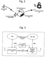
- the console 100 may be configured having two different radio subsystems.
- the first wireless system is an 802.11b/g standard compliant module (WiFi) within the network interface 124, which is used for wireless home network connectivity via an access point 156. This can be used in place of a standard Ethernet connection to add wireless networking ability to access the Internet or remote PC's.
- WiFi 802.11b/g standard compliant module
- the second is a frequency-hopping, low transmit power system within the wireless adapter 148 for wireless connectivity of various peripherals (e.g., a wireless accessory 154) which can be used to operate the games.
- both radios operate in the Industrial-Scientific-Medical (ISM) 2.4 GHz band and each radio has the potential to create RF interference into the other's operation.
- the present invention advantageously provides a coordination activity between them which allow these radios to share the same spectrum in order to reduce RF interference between the two radio sub-systems.
- the interference problem is most problematic when: (1) the WiFi radio in the network interface 124 is transmitting and the wireless adapter 148 is receiving, regardless of RF channel used in the ISM band, and (2) the transmitter in the wireless adapter 148 is transmitting on an overlapping RF channel with the WiFi radio.
- the reason the first case is a problem is because of a combination of two factors: the absolute transmit power of the WiFi transmitter (up to +20dBm), and the out-of-band rejection capability of the wireless adapter 148.
- the absolute transmit power of the WiFi transmitter up to +20dBm
- the out-of-band rejection capability of the wireless adapter 148 When these two items are combined, there is a significant amount of de-sensitivity occurring within the wireless adapter 148.
- the receiver sensitivity drops because of this interference. This has a significant effect on the overall distance the wireless accessory 154 can be located away from the console 100. In other words, it will diminish the region of RF coverage. It will also impact the battery life of the wireless accessory 154 because of the need for extra transmit power levels necessary to maintain the RF signal quality.
- the radio in the wireless adapter 148 when the radio in the wireless adapter 148 is transmitting on an RF channel that overlaps those being used by the WiFi radio in the network interface 124, it will de-sensitize the WiFi radio receiver. Further, if the WiFi radio is transmitting, the wireless adapter receiver signal strength will be too small relative to the WiFi transmitter and the wireless adapter communications channel (i.e., 148 -> 154) will not operate.
- the present invention delays the WiFi network transmissions away from the critical receive times of the radio in the wireless adapter 148. Since the WiFi network is packet based, there may be some increase in data packet latency, however, this should be small.
- the WiFi device When the WiFi device receives a packet, it must acknowledge the receipt of the packet with an ACK packet. This must start transmission immediately after the SIFS timing period (e.g., 10 usec). The transmission time of the ACK varies from 34 usec to 50 usec, depending on link data rates. If the ACK is not sent then the original packet is retransmitted. When this occurs, there is a significant impact on the WiFi network performance.
- the present invention accounts for this by allowing the WiFi radio to ignore the collaboration request and transmit the ACK packet.
- WiFi radio is in the middle of transmitting a packet when the collaboration request is made. Depending upon how much of the packet remains before the receive window opens and the rate of transmission, a packet may be aborted. However it will depend upon the exact implementation of the WiFi solution.
- the WiFi protocol is friendly to a premature packet termination since packet corruption common occurrence from the RF channel. The system will simply retransmit the packet at a later time. A packet should not be repetitively aborted since there are limits to the number of times the WiFi protocol will attempt to retransmit a packet before giving up on the wireless link. This will also impact the rate adaptation algorithm.
- the Access Point 156 would likely interpret these error events as problems with the RF channel and drop the transmission rate of the link. This has the impact of reducing data throughput and also causes more interference because the WiFi packets will now be longer and consume more time.
- the wireless adapter 148 needs to use a channel that overlaps the WiFi channel (i.e., link 124 -> 156). As above, if the WiFi radio in the network interface 124 transmits, the wireless accessory radio link (148 -> 154) will not function in either the transmit or receive state. In this situation the WiFi transmitter is held off from activating during the receive and transmit times of the wireless accessory 154.
- the wireless adapter 148 When the wireless adapter 148 transmits on an overlapping channel, it has the same effect on the WiFi receiver in the network interface 124. In this case, there is nothing which can be done to prevent the situation.
- the WiFi radio must operate with the interference. In this instance, the WiFi radio understands the source of the interference and may avoid receiving data packets during those critical periods.
- the WiFi transmitter Since the WiFi transmitter will be suspended during reasonability significant portions of time, there will be potential impacts to the amount of throughput which can be achieved by the WiFi radio. If the WiFi radio is attempting to stream data in the uplink direction (i.e., the transmitter is very active), the throughput would drop significantly. Because the two radio networks are sharing the same spectrum and each has the ability to impact the performance of the other, the present invention has given priority to the wireless accessory radio link.
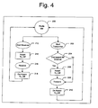
- Fig. 3 provides a high level block diagram of the collaboration solution.
- the decision logic which functions within the wireless adapter 148 informs the WiFi radio within the network interface 124 of critical time periods when its receiver is operating.
- the following exemplary priority rule may be implemented: the wireless adapter 148 packets have priority over WiFi packets transmitted via the network interface 124.
- the collaboration solution of the present invention consists of various parts. Generally, it can be broken down into the following: (1) decision logic within the Wireless adapter 148, (2) decision logic within the WiFi network interface 124, (3) a real time collaboration signaling path 149 from the wireless adapter 148 to the WiFi radio in the network interface 124, and (4) a software driver communications path 151 between the wireless adapter 148 and the WiFi radio in the network interface 124.
- the collaboration signaling path 149 from the wireless adapter 148 to the WiFi radio in the network interface 124 may be a separate signaling line provided in a USB connector interface to the USB controller 128 or another method. This path provides communications to the WiFi radio whenever the wireless adapter 148 requires that the WiFi radio in the network interface 124 suspend transmission activities because the wireless adapter 148 needs to utilize the RF channel.
- the collaboration signaling path 149 is labeled, Tx_Off. When Tx_Off is active, it is a request for the WiFi transmitter in the network interface 124 not to be in an active transmitting state (e.g., the output power is ⁇ -20 dBm). When the Tx_Off signal is inactive, the WiFi transmitter in the network interface 124 is free to turn on, if required.
- the software communications path 151 between the wireless adapter 148 and the WiFi radio in the network interface 124 is also used to permit the sharing of information between the two radio systems, which facilitates more intelligent decisions about the use of the shared spectrum.
- This information stream may be viewed as a low speed path. This is provided for two reasons. First, to reduce the software load on the console 100. which is responsible for transporting the information exchange. Second, the amount of information is limited to configuration information about the specifics of the two radio systems.
- the information exchanged consists of the following between the WiFi radio to wireless adapter: WiFi RF channel in use, collaboration On/Off and retransmission On/Off.
- wireless accessory configuration connections which timeslots are in active use, overlapping channels, when the wireless adapter is going to be using the WiFi channel for transmit activities, and a WiFi channel the wireless adapter radio is avoiding.
- Fig. 4 shows the State Diagram of the wireless adapter decision logic at a high level.
- the wireless adapter 148 will not suspend the WiFi transmissions when it is transmitting (see, e.g., steps 202 and 208). However, in the situations where it is necessary to utilize the overlapping channels, the wireless adapter 148 will assert the collaboration signal 149 in those cases (see, e.g., steps 204 and 206). The wireless adapter 148 will be provided the WiFi channel number which is being used on that network. The wireless adapter 148 determines when a potential overlap occurs. It is noted that because of the operating frequency differences when the wireless adapter is operating in an 802.11 a mode, the collaboration signal 149 is ignored.
- TDMA Time Division Multiple Access
- each attached wireless device is assigned to a fixed time slot. That time slot is used exclusively by only that device. Since the radios are a half-duplex device, the same RF frequency is time shared between receive and transmit functions.
- the general principle of operation is to inform the WiFi radio in the network interface 124 whenever critical receive times (R1 to R5) occur on the wireless adapter radio link (148 ->154). This is dependant upon which devices are active on the link. For example, some systems will only be operating with one wireless accessory 154 and only the R1 slot is used. In that case, the system will not need to receive most of the time and the WiFi radio will have access to most of the spectrum.
- the collaboration logic of the present invention tracks which time slots are in active use and which are not. This state information is made available to the WiFi radio to permit fair-sharing. For each active wireless accessory 154, the collaboration signal 149 is active during its corresponding receive time slot.
- the following information may be used to construct an algorithm for determining transmissions by the network interface 124.
- the network interface 124 knows a-priori the state TX_OFF will be when it is scheduling a transmission. Accordingly, the following information should be considered:
- the Tx_Off 149 provides a warning period (see, Fig 7 ) where it gives an in-progress transmit packet a change to complete.
- the warning period may be between 30 and 500 usec. If the packet is in the middle of being transmitted, the WiFi module in the network interface 124 will attempt to complete the transmission within the warning period. This is dependant upon the amount of the packet that remains and the rate the packet is being transmitted. Otherwise, the WiFi module aborts the transmission at the end of the warning period. Network interface 124 packets that are aborted because of the collaboration signal should not be counted as a retry event in the 802.11 protocol.
- wireless adapter 148 needs to disable network interface 124 transmissions during other slots times for individual frames.
- the TX_OFF signal will indicate the request.
- the network interface 124 transmission respects the TX_OFF signal state and reschedules any pending transmissions.
- overlapped frequencies are being used, the network interface 124 respects the collaboration signal 149, but there are alternatives to consider:
- the TX_OFF signal may be ignored.
- the collaboration signal may be ignored.
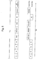
- Fig. 7 shows a more detailed timing information of an uplink receive slot for wireless accessories 154. It also indicates the corresponding state of the collaboration signal 149.
- the collaboration signal should be asserted as soon as possible at the beginning of the packet. This means the signal should be active at the start of the RF Setup field even though the receiver will not be demodulating information during this period. This is intended to provide advance warning to the WiFi radio in the network interface 124 so it can decide what action to initiate.
- the WiFi module will expect to have a warning period that is an interval of time where it can continue use of the spectrum.
- the collaboration signal is de-asserted at the end of the Data 1 field. It will not activate again until the next active wireless accessory timeslot is reached. If both the Data 1 and Data 2 slots are being used, the collaboration signal will not de-assert during the intervening Guard field, but remain active until the end of the complete packet. If the subsequent timeslot is going to be used, the collaboration signal will not de-assert during the Guard period at the end of the Data 2 field. If only a Data 2 slot is used and not a wireless accessory Data 1 slot, the collaboration signal will be asserted for the warning period before the start of the Data 2 Field.
- the collaboration signal provides the warning period to the WiFi radio. This will occur for each wireless accessory field of the Upstream R5 Packets regardless of timeslot location. At the end of the individual fields (R5-1 to R5 - 4), the collaboration signal will return in the inactive state. If the adjacent wireless accessory field is going to be utilized, the collaboration signal will remain asserted during the intervening Guard period. If the wireless adapter radio has not detected an incoming transmission, the collaboration signal will be de-asserted.
- the WiFi RF channel information is provided to the wireless adapter radio.
- This information is used by the Adaptive Frequency Hopping (AFH) Algorithm of the wireless adapter radio to avoid using any of the WiFi spectrum.
- the WiFi channels use 20 MHz of bandwidth
- the wireless adapter channel use 2 MHz of bandwidth, and there is only 80 MHz of total spectrum, there are times there may not be sufficient spectrum for the AFH algorithm to conform to regulatory requirements. This can occur if there are other interference sources present in the environment. In these situations, it can be better for the wireless adapter radio to use the WiFi spectrum If this is the case, then the wireless adapter and WiFi radios cannot both transmit on the overlapping spectrum at the same time period.
- the wireless adapter radio asserts the collaboration signal whenever overlapping spectrum is being used and the wireless adapter radio is transmitting or receiving. This means the collaboration signal will be active during the Downlink Broadcast 1 and the Downlink Broadcast 2 timeslots. The collaboration signal is active for the warning period before turning on the transmitter in the wireless adapter and remains active until the wireless adapter's transmission has completed.
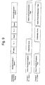
- the collaboration signal must also be asserted during the respective Voice timeslots. This is shown in Fig. 8 .
- the collaboration signal remains active until either the data packet has completed or the Downlink Broadcast field has completed. If both data fields are active then the collaboration signal is asserted through the entire Downstream Tz field and the Downlink Broadcast field. If three or more data fields are active and three or more wireless accessory data receive fields are active then the collaboration signal will be asserted for at the beginning of the first wireless accessory Data field in use and remain active until the last data field in the second Downlink Data field. The collaboration signal will not assert during the Uplink R5 fields regardless of their state. This is done to permit some amount of bandwidth to the WiFi radio during these situations.
- An exemplary hardware implementation of the collaboration design consists of a single logic signal (Tx _Off).
- the signal originates on the wireless adapter radio and terminated on the WiFi module. Whenever the wireless adapter module wants to suspend the WiFi module's transmissions, it sets the Tx_Off signal to a logic HIGH. When the wireless adapter module has completed its activities, it will de-assert Tx_Off to logic LOW.
- a messaging communication channel between the wireless adapter radio and the WiFi radio.
- the purpose of this channel is to provide configuration information to both sides of the link. This is done to permit intelligent decision making on the two different radio protocols and make more efficient use of the shared spectrum. Messaging is performed over USB interfaces associated with the USB controllers 126 and 128. The wireless adapter driver in the console 100 will exchange the appropriate messages at the correct time through the WiFi driver.
- This latter type of messages contains the active WiFi channel in use.
- the channel selection is performed by the Access Point 156 of the WiFi network selecting an appropriate channel to use.
- the WiFi radio scans the different channels and attaches to the correct network. The following parameters are used to indicate which RF channel in the 2.4GHz ISM band is active.
- the Channel_number 0 will be used. Since the WiFi channel can change during normal operation of the WiFi network, the wireless adapter driver updates the wireless adapter radio upon this event.
- Collaboration Start/Stop Message This message is used to enable or disable the collaboration signal.
- the collaboration signal returns to a de-asserted state and remains in that state until it is re-enabled by the start message.
- R5 Start/Stop Message This message is used to enable or disable the collaboration signal during the Uplink R5 time slot. Since the duty cycle of this timeslot is expected to be small, it may be better to simply disable the collaboration signal from being asserted during this interval. When the message indicates stop, the collaboration signal will not be asserted during the Uplink R5 slot. Otherwise, it will function as normal This section outlines the messages which are sent from the wireless adapter radio to the WiFi radio.
- WiFi_Channel Message contains the active WiFi channel in which the wireless adapter radio believes to be in use. It uses the same parameters as listed in Table 2. This message is only intended for debug purposes.
- This message provides information on the type of active connections which exist on the wireless adapter radio link and which fields are being used. This is used by the WiFi collaboration logic to determine appropriate decisions. It also includes the length of various fields This is provided for future compatibility if the field definitions ever change in size. This message only needs to be sent to the WiFi radio at initialization time and whenever any of the fields change state.
Landscapes
- Engineering & Computer Science (AREA)
- Computer Networks & Wireless Communication (AREA)
- Signal Processing (AREA)
- Mobile Radio Communication Systems (AREA)
- Small-Scale Networks (AREA)
- Transmitters (AREA)
Applications Claiming Priority (1)
| Application Number | Priority Date | Filing Date | Title |
|---|---|---|---|
| US11/091,557 US7430400B2 (en) | 2005-03-28 | 2005-03-28 | WiFi collaboration method to reduce RF interference with wireless adapter |
Publications (2)
| Publication Number | Publication Date |
|---|---|
| EP1708420A1 EP1708420A1 (en) | 2006-10-04 |
| EP1708420B1 true EP1708420B1 (en) | 2013-04-17 |
Family
ID=36603657
Family Applications (1)
| Application Number | Title | Priority Date | Filing Date |
|---|---|---|---|
| EP06111547.3A Not-in-force EP1708420B1 (en) | 2005-03-28 | 2006-03-22 | WIFI collaboration method to reduce RF interference between a wireless network interface and a wireless adapter |
Country Status (5)
| Country | Link |
|---|---|
| US (1) | US7430400B2 (enExample) |
| EP (1) | EP1708420B1 (enExample) |
| JP (1) | JP4740767B2 (enExample) |
| CN (1) | CN1841970B (enExample) |
| TW (1) | TWI387388B (enExample) |
Families Citing this family (40)
| Publication number | Priority date | Publication date | Assignee | Title |
|---|---|---|---|---|
| US20070092046A1 (en) * | 2005-10-25 | 2007-04-26 | Hyun Lee | Method of reducing interference among wireless network by intentionally violating the communication protocol |
| US8244297B2 (en) * | 2006-12-12 | 2012-08-14 | Intel Corporation | Preventing self-induced interference in dual-radio device |
| JP5013843B2 (ja) * | 2006-12-18 | 2012-08-29 | パナソニック株式会社 | ゲーム機器およびゲームシステム |
| US8228922B2 (en) * | 2006-12-29 | 2012-07-24 | Nokia Corporation | Multiradio synchronization and scheduling control |
| US7889756B2 (en) | 2006-12-29 | 2011-02-15 | Nokia Corporation | Apparatus, methods and computer program products providing temporary link quality modification for multiradio control |
| US20080279137A1 (en) * | 2007-05-10 | 2008-11-13 | Nokia Corporation | Discontinuous inquiry for wireless communication |
| US7872974B2 (en) | 2007-09-27 | 2011-01-18 | Freescale Semiconductor Inc. | System and method for handling or avoiding disruptions in wireless communication |
| EP2073598B1 (en) * | 2007-12-21 | 2017-10-04 | Telefonaktiebolaget LM Ericsson (publ) | Technique for providing network access to different entities |
| US8135344B2 (en) * | 2008-02-13 | 2012-03-13 | Apple Inc. | Method for using bluetooth module to process non-bluetooth signals |
| CN101364847B (zh) * | 2008-09-25 | 2011-06-29 | 上海交通大学 | 认知无线电中的协作通信方法 |
| USD615961S1 (en) * | 2009-01-06 | 2010-05-18 | Shenzhen Fujiatai Technology Co. Ltd. | WIFI radio |
| TWI414163B (zh) | 2009-12-04 | 2013-11-01 | Ind Tech Res Inst | 異質無線感測網路橋接裝置以及異質無線感測網路橋接裝置之控制方法以及流量平衡方法 |
| CN102771147B (zh) | 2010-02-25 | 2016-01-20 | 美国博通公司 | 用于4GWiMAX/LTE-WiFi/BT共存时域法的方法及系统 |
| US8582551B2 (en) | 2010-05-26 | 2013-11-12 | Intel Corporation | Device, system and method of wireless communication over non-contiguous channels |
| US8838046B2 (en) | 2010-06-18 | 2014-09-16 | Mediatek Inc. | System and method of hybrid FDM/TDM coexistence interference avoidance |
| WO2011157235A1 (en) | 2010-06-18 | 2011-12-22 | Mediatek Inc. | System and method for coordinating multiple radio transceivers within the same device platform |
| US9246603B2 (en) | 2010-08-12 | 2016-01-26 | Mediatek Inc. | Method of in-device interference mitigation for cellular, bluetooth, WiFi, and satellite systems coexistence |
| US8780880B2 (en) | 2010-10-01 | 2014-07-15 | Mediatek Singapore Pte, Ltd. | Method of TDM in-device coexistence interference avoidance |
| US8971813B2 (en) | 2011-04-26 | 2015-03-03 | Broadcom Corporation | Method and apparatus for avoiding in-device interference |
| GB2490347B (en) * | 2011-04-27 | 2013-05-01 | Renesas Mobile Corp | Method and apparatus for avoiding in-device interference |
| GB2482761B (en) * | 2011-06-17 | 2015-12-23 | Airwave Solutions Ltd | Communications system, apparatus and method |
| US8862060B2 (en) | 2012-02-15 | 2014-10-14 | Apple Inc. | Methods for mitigating effects of radio-frequency interference |
| US9820158B2 (en) * | 2012-03-07 | 2017-11-14 | Qualcomm Incorporated | Multi-radio interference mitigation via frequency selectivity |
| US9433003B2 (en) | 2012-03-07 | 2016-08-30 | Qualcomm Incorporated | Multi-radio coexistence via timing controls for radios using the same radio access technology |
| CN103369711A (zh) * | 2012-03-31 | 2013-10-23 | 华为终端有限公司 | 通信连接建立方法及终端设备 |
| CN103513734B (zh) * | 2012-06-15 | 2016-12-21 | 台达电子工业股份有限公司 | 适配器、电子装置以及无线通信系统 |
| US9191063B2 (en) | 2013-03-12 | 2015-11-17 | Rosemount Inc. | Channel grey listing |
| US9492741B2 (en) | 2013-05-22 | 2016-11-15 | Microsoft Technology Licensing, Llc | Wireless gaming protocol |
| CN103415012A (zh) * | 2013-08-15 | 2013-11-27 | 惠州Tcl移动通信有限公司 | 一种无线路由器的鉴权方法和鉴权装置 |
| US9510281B2 (en) | 2014-09-19 | 2016-11-29 | Qualcomm Incorporated | Priority arbitration for interference mitigation |
| WO2016045134A1 (zh) * | 2014-09-28 | 2016-03-31 | 华为技术有限公司 | 一种传输数据的方法、设备及系统 |
| US10701630B2 (en) | 2014-10-24 | 2020-06-30 | Gainspan Corporation | Reducing power consumption in wireless stations providing network connectivity for embedded devices |
| US9503987B2 (en) | 2014-11-11 | 2016-11-22 | Gainspan Corporation | Reducing power consumption in wireless stations executing various client applications |
| JP5900768B2 (ja) * | 2015-04-16 | 2016-04-06 | ヤマハ株式会社 | 無線データ伝送方法 |
| KR101796985B1 (ko) | 2015-12-28 | 2017-11-13 | 현대자동차주식회사 | 자동차 및 자동차의 와이파이 통신 제어 방법 |
| US9699684B1 (en) * | 2016-07-28 | 2017-07-04 | Blackfire Research Corporation | Low-latency multimedia using dual wireless adapters |
| US10412663B2 (en) | 2017-03-21 | 2019-09-10 | Ademco Inc. | Systems and methods for detecting and avoiding radio interference in a wireless sensor network |
| US10916106B2 (en) | 2017-12-26 | 2021-02-09 | Ademco Inc. | Systems and methods for efficient utilization of wireless bandwidth |
| EP3884604B1 (en) | 2018-11-22 | 2025-11-05 | Telefonaktiebolaget LM Ericsson (publ) | Acknowlegment for simultaneous transmission and reception |
| US11265725B2 (en) | 2019-02-15 | 2022-03-01 | Ademco Inc. | Systems and methods for allocating wireless communication channels |
Citations (1)
| Publication number | Priority date | Publication date | Assignee | Title |
|---|---|---|---|---|
| EP0944176A1 (en) * | 1998-03-20 | 1999-09-22 | Telefonaktiebolaget Lm Ericsson | Dual mode communication device and method of operation |
Family Cites Families (7)
| Publication number | Priority date | Publication date | Assignee | Title |
|---|---|---|---|---|
| DE60030086T2 (de) | 2000-01-20 | 2007-01-04 | Lucent Technologies Inc. | Interoperabilität von Bluetooth und IEEE 802.11 |
| US6684062B1 (en) * | 2000-10-25 | 2004-01-27 | Eleven Engineering Incorporated | Wireless game control system |
| WO2004045082A2 (en) * | 2002-11-13 | 2004-05-27 | Agere Systems Inc. | Interoperability and coexistence between two disparate communication systems |
| US20040242159A1 (en) * | 2003-05-28 | 2004-12-02 | Roberto Calderon | Interoperability and coexistence between two disparate communication systems |
| US7849491B2 (en) * | 2002-12-10 | 2010-12-07 | Onlive, Inc. | Apparatus and method for wireless video gaming |
| US7295528B2 (en) * | 2003-03-12 | 2007-11-13 | Broadcom Corporation | Peer to peer wireless communication conflict resolution |
| CN1268069C (zh) * | 2003-05-28 | 2006-08-02 | 重庆邮电大学 | 基于蓝牙技术的自动化网络通信控制方法及系统 |
-
2005
- 2005-03-28 US US11/091,557 patent/US7430400B2/en not_active Expired - Lifetime
-
2006
- 2006-02-06 TW TW095103952A patent/TWI387388B/zh not_active IP Right Cessation
- 2006-02-28 JP JP2006053072A patent/JP4740767B2/ja not_active Expired - Fee Related
- 2006-02-28 CN CN2006100515431A patent/CN1841970B/zh not_active Expired - Fee Related
- 2006-03-22 EP EP06111547.3A patent/EP1708420B1/en not_active Not-in-force
Patent Citations (1)
| Publication number | Priority date | Publication date | Assignee | Title |
|---|---|---|---|---|
| EP0944176A1 (en) * | 1998-03-20 | 1999-09-22 | Telefonaktiebolaget Lm Ericsson | Dual mode communication device and method of operation |
Also Published As
| Publication number | Publication date |
|---|---|
| TW200642491A (en) | 2006-12-01 |
| US20060217071A1 (en) | 2006-09-28 |
| JP4740767B2 (ja) | 2011-08-03 |
| EP1708420A1 (en) | 2006-10-04 |
| JP2006279943A (ja) | 2006-10-12 |
| CN1841970B (zh) | 2011-09-07 |
| US7430400B2 (en) | 2008-09-30 |
| TWI387388B (zh) | 2013-02-21 |
| CN1841970A (zh) | 2006-10-04 |
Similar Documents
| Publication | Publication Date | Title |
|---|---|---|
| EP1708420B1 (en) | WIFI collaboration method to reduce RF interference between a wireless network interface and a wireless adapter | |
| US9649560B2 (en) | RF collaboration method to reduce RF interference with wireless adapter | |
| US8396021B2 (en) | Gaming console wireless protocol for peripheral devices | |
| EP2673898B1 (en) | Systems and methods for providing categorized channel reservation | |
| US10531316B1 (en) | Methods and systems for using shared antennas for multi-protocol communication | |
| KR20110114694A (ko) | 스펙트럼 공유를 위한 분산된 우선 순위화된 경쟁 | |
| US8639284B2 (en) | System and method providing concurrent multimode communication | |
| US8831015B2 (en) | MoCA-WiFi multiplexing | |
| US8891508B2 (en) | Synchronized channel access in coexisting wireless networks | |
| US11553506B2 (en) | Multi-radio coexistence aware intelligent WiFi data aggregation | |
| US20250142559A1 (en) | Coexistence management in wireless communications | |
| CN116567596A (zh) | 一种天线配置方法和设备 | |
| US20070298717A1 (en) | System scheduler for mobile terminals | |
| CN119276289B (zh) | 一种数据传输方法及电子设备 | |
| US20240406855A1 (en) | Transmitting data to a wireless communication device | |
| EP3813267B1 (en) | Radio module, method to operate a radio module, radio terminal, method to operate a radio terminal | |
| CN120751432A (zh) | 无线音频数据传输方法、装置及相关设备 | |
| US20240422768A1 (en) | Systems, methods, and devices for wireless device coexistence enhancement using activity overlap | |
| JP7730269B2 (ja) | 無線通信デバイスのためのネットワークトラフィックのスケジューリング | |
| US20250089039A1 (en) | Long Range UWB and Wi-Fi Coexistence | |
| CN121013185A (zh) | 资源共享的方法、装置及通信设备 | |
| CN120786654A (zh) | 一种基于WiFi和蓝牙共存的数据传输方法、无线通信装置 | |
| CN105657802A (zh) | 受限无线设备低功耗介质接入的方法及系统 | |
| HK1149395B (en) | Time multiplexing for coexistence within multiple communication systems |
Legal Events
| Date | Code | Title | Description |
|---|---|---|---|
| PUAI | Public reference made under article 153(3) epc to a published international application that has entered the european phase |
Free format text: ORIGINAL CODE: 0009012 |
|
| AK | Designated contracting states |
Kind code of ref document: A1 Designated state(s): AT BE BG CH CY CZ DE DK EE ES FI FR GB GR HU IE IS IT LI LT LU LV MC NL PL PT RO SE SI SK TR |
|
| AX | Request for extension of the european patent |
Extension state: AL BA HR MK YU |
|
| 17P | Request for examination filed |
Effective date: 20070330 |
|
| 17Q | First examination report despatched |
Effective date: 20070504 |
|
| AKX | Designation fees paid |
Designated state(s): AT BE BG CH CY CZ DE DK EE ES FI FR GB GR HU IE IS IT LI LT LU LV MC NL PL PT RO SE SI SK TR |
|
| REG | Reference to a national code |
Ref country code: DE Ref legal event code: R079 Ref document number: 602006035689 Country of ref document: DE Free format text: PREVIOUS MAIN CLASS: H04L0012280000 Ipc: H04W0016140000 |
|
| GRAP | Despatch of communication of intention to grant a patent |
Free format text: ORIGINAL CODE: EPIDOSNIGR1 |
|
| RIC1 | Information provided on ipc code assigned before grant |
Ipc: H04W 16/14 20090101AFI20121016BHEP |
|
| RAP1 | Party data changed (applicant data changed or rights of an application transferred) |
Owner name: MICROSOFT CORPORATION |
|
| GRAS | Grant fee paid |
Free format text: ORIGINAL CODE: EPIDOSNIGR3 |
|
| GRAA | (expected) grant |
Free format text: ORIGINAL CODE: 0009210 |
|
| AK | Designated contracting states |
Kind code of ref document: B1 Designated state(s): AT BE BG CH CY CZ DE DK EE ES FI FR GB GR HU IE IS IT LI LT LU LV MC NL PL PT RO SE SI SK TR |
|
| REG | Reference to a national code |
Ref country code: GB Ref legal event code: FG4D |
|
| REG | Reference to a national code |
Ref country code: CH Ref legal event code: EP |
|
| REG | Reference to a national code |
Ref country code: IE Ref legal event code: FG4D |
|
| REG | Reference to a national code |
Ref country code: AT Ref legal event code: REF Ref document number: 607929 Country of ref document: AT Kind code of ref document: T Effective date: 20130515 |
|
| REG | Reference to a national code |
Ref country code: DE Ref legal event code: R096 Ref document number: 602006035689 Country of ref document: DE Effective date: 20130613 |
|
| REG | Reference to a national code |
Ref country code: AT Ref legal event code: MK05 Ref document number: 607929 Country of ref document: AT Kind code of ref document: T Effective date: 20130417 |
|
| REG | Reference to a national code |
Ref country code: LT Ref legal event code: MG4D |
|
| REG | Reference to a national code |
Ref country code: NL Ref legal event code: VDEP Effective date: 20130417 |
|
| PG25 | Lapsed in a contracting state [announced via postgrant information from national office to epo] |
Ref country code: PT Free format text: LAPSE BECAUSE OF FAILURE TO SUBMIT A TRANSLATION OF THE DESCRIPTION OR TO PAY THE FEE WITHIN THE PRESCRIBED TIME-LIMIT Effective date: 20130819 Ref country code: ES Free format text: LAPSE BECAUSE OF FAILURE TO SUBMIT A TRANSLATION OF THE DESCRIPTION OR TO PAY THE FEE WITHIN THE PRESCRIBED TIME-LIMIT Effective date: 20130728 Ref country code: SI Free format text: LAPSE BECAUSE OF FAILURE TO SUBMIT A TRANSLATION OF THE DESCRIPTION OR TO PAY THE FEE WITHIN THE PRESCRIBED TIME-LIMIT Effective date: 20130417 Ref country code: LT Free format text: LAPSE BECAUSE OF FAILURE TO SUBMIT A TRANSLATION OF THE DESCRIPTION OR TO PAY THE FEE WITHIN THE PRESCRIBED TIME-LIMIT Effective date: 20130417 Ref country code: IS Free format text: LAPSE BECAUSE OF FAILURE TO SUBMIT A TRANSLATION OF THE DESCRIPTION OR TO PAY THE FEE WITHIN THE PRESCRIBED TIME-LIMIT Effective date: 20130817 Ref country code: GR Free format text: LAPSE BECAUSE OF FAILURE TO SUBMIT A TRANSLATION OF THE DESCRIPTION OR TO PAY THE FEE WITHIN THE PRESCRIBED TIME-LIMIT Effective date: 20130718 Ref country code: FI Free format text: LAPSE BECAUSE OF FAILURE TO SUBMIT A TRANSLATION OF THE DESCRIPTION OR TO PAY THE FEE WITHIN THE PRESCRIBED TIME-LIMIT Effective date: 20130417 Ref country code: AT Free format text: LAPSE BECAUSE OF FAILURE TO SUBMIT A TRANSLATION OF THE DESCRIPTION OR TO PAY THE FEE WITHIN THE PRESCRIBED TIME-LIMIT Effective date: 20130417 Ref country code: BE Free format text: LAPSE BECAUSE OF FAILURE TO SUBMIT A TRANSLATION OF THE DESCRIPTION OR TO PAY THE FEE WITHIN THE PRESCRIBED TIME-LIMIT Effective date: 20130417 Ref country code: SE Free format text: LAPSE BECAUSE OF FAILURE TO SUBMIT A TRANSLATION OF THE DESCRIPTION OR TO PAY THE FEE WITHIN THE PRESCRIBED TIME-LIMIT Effective date: 20130417 |
|
| PG25 | Lapsed in a contracting state [announced via postgrant information from national office to epo] |
Ref country code: LV Free format text: LAPSE BECAUSE OF FAILURE TO SUBMIT A TRANSLATION OF THE DESCRIPTION OR TO PAY THE FEE WITHIN THE PRESCRIBED TIME-LIMIT Effective date: 20130417 Ref country code: PL Free format text: LAPSE BECAUSE OF FAILURE TO SUBMIT A TRANSLATION OF THE DESCRIPTION OR TO PAY THE FEE WITHIN THE PRESCRIBED TIME-LIMIT Effective date: 20130417 Ref country code: BG Free format text: LAPSE BECAUSE OF FAILURE TO SUBMIT A TRANSLATION OF THE DESCRIPTION OR TO PAY THE FEE WITHIN THE PRESCRIBED TIME-LIMIT Effective date: 20130717 Ref country code: CY Free format text: LAPSE BECAUSE OF FAILURE TO SUBMIT A TRANSLATION OF THE DESCRIPTION OR TO PAY THE FEE WITHIN THE PRESCRIBED TIME-LIMIT Effective date: 20130417 |
|
| PG25 | Lapsed in a contracting state [announced via postgrant information from national office to epo] |
Ref country code: EE Free format text: LAPSE BECAUSE OF FAILURE TO SUBMIT A TRANSLATION OF THE DESCRIPTION OR TO PAY THE FEE WITHIN THE PRESCRIBED TIME-LIMIT Effective date: 20130417 Ref country code: SK Free format text: LAPSE BECAUSE OF FAILURE TO SUBMIT A TRANSLATION OF THE DESCRIPTION OR TO PAY THE FEE WITHIN THE PRESCRIBED TIME-LIMIT Effective date: 20130417 Ref country code: DK Free format text: LAPSE BECAUSE OF FAILURE TO SUBMIT A TRANSLATION OF THE DESCRIPTION OR TO PAY THE FEE WITHIN THE PRESCRIBED TIME-LIMIT Effective date: 20130417 Ref country code: CZ Free format text: LAPSE BECAUSE OF FAILURE TO SUBMIT A TRANSLATION OF THE DESCRIPTION OR TO PAY THE FEE WITHIN THE PRESCRIBED TIME-LIMIT Effective date: 20130417 |
|
| PLBE | No opposition filed within time limit |
Free format text: ORIGINAL CODE: 0009261 |
|
| STAA | Information on the status of an ep patent application or granted ep patent |
Free format text: STATUS: NO OPPOSITION FILED WITHIN TIME LIMIT |
|
| PG25 | Lapsed in a contracting state [announced via postgrant information from national office to epo] |
Ref country code: IT Free format text: LAPSE BECAUSE OF FAILURE TO SUBMIT A TRANSLATION OF THE DESCRIPTION OR TO PAY THE FEE WITHIN THE PRESCRIBED TIME-LIMIT Effective date: 20130417 Ref country code: RO Free format text: LAPSE BECAUSE OF FAILURE TO SUBMIT A TRANSLATION OF THE DESCRIPTION OR TO PAY THE FEE WITHIN THE PRESCRIBED TIME-LIMIT Effective date: 20130417 Ref country code: NL Free format text: LAPSE BECAUSE OF FAILURE TO SUBMIT A TRANSLATION OF THE DESCRIPTION OR TO PAY THE FEE WITHIN THE PRESCRIBED TIME-LIMIT Effective date: 20130417 |
|
| 26N | No opposition filed |
Effective date: 20140120 |
|
| REG | Reference to a national code |
Ref country code: DE Ref legal event code: R097 Ref document number: 602006035689 Country of ref document: DE Effective date: 20140120 |
|
| PG25 | Lapsed in a contracting state [announced via postgrant information from national office to epo] |
Ref country code: LU Free format text: LAPSE BECAUSE OF FAILURE TO SUBMIT A TRANSLATION OF THE DESCRIPTION OR TO PAY THE FEE WITHIN THE PRESCRIBED TIME-LIMIT Effective date: 20140322 |
|
| REG | Reference to a national code |
Ref country code: CH Ref legal event code: PL |
|
| REG | Reference to a national code |
Ref country code: FR Ref legal event code: ST Effective date: 20141128 |
|
| REG | Reference to a national code |
Ref country code: IE Ref legal event code: MM4A |
|
| PG25 | Lapsed in a contracting state [announced via postgrant information from national office to epo] |
Ref country code: LI Free format text: LAPSE BECAUSE OF NON-PAYMENT OF DUE FEES Effective date: 20140331 Ref country code: CH Free format text: LAPSE BECAUSE OF NON-PAYMENT OF DUE FEES Effective date: 20140331 Ref country code: IE Free format text: LAPSE BECAUSE OF NON-PAYMENT OF DUE FEES Effective date: 20140322 Ref country code: FR Free format text: LAPSE BECAUSE OF NON-PAYMENT OF DUE FEES Effective date: 20140331 |
|
| REG | Reference to a national code |
Ref country code: GB Ref legal event code: 732E Free format text: REGISTERED BETWEEN 20150312 AND 20150318 |
|
| REG | Reference to a national code |
Ref country code: DE Ref legal event code: R082 Ref document number: 602006035689 Country of ref document: DE Representative=s name: OLSWANG GERMANY LLP, DE |
|
| REG | Reference to a national code |
Ref country code: DE Ref legal event code: R081 Ref document number: 602006035689 Country of ref document: DE Owner name: MICROSOFT TECHNOLOGY LICENSING, LLC, REDMOND, US Free format text: FORMER OWNER: MICROSOFT CORP., REDMOND, WASH., US Effective date: 20150430 Ref country code: DE Ref legal event code: R082 Ref document number: 602006035689 Country of ref document: DE Representative=s name: OLSWANG GERMANY LLP, DE Effective date: 20150430 Ref country code: DE Ref legal event code: R081 Ref document number: 602006035689 Country of ref document: DE Owner name: MICROSOFT TECHNOLOGY LICENSING, LLC, REDMOND, US Free format text: FORMER OWNER: MICROSOFT CORP., REDMOND, WASH., US Effective date: 20130419 |
|
| PG25 | Lapsed in a contracting state [announced via postgrant information from national office to epo] |
Ref country code: MC Free format text: LAPSE BECAUSE OF FAILURE TO SUBMIT A TRANSLATION OF THE DESCRIPTION OR TO PAY THE FEE WITHIN THE PRESCRIBED TIME-LIMIT Effective date: 20130417 |
|
| PG25 | Lapsed in a contracting state [announced via postgrant information from national office to epo] |
Ref country code: HU Free format text: LAPSE BECAUSE OF FAILURE TO SUBMIT A TRANSLATION OF THE DESCRIPTION OR TO PAY THE FEE WITHIN THE PRESCRIBED TIME-LIMIT; INVALID AB INITIO Effective date: 20060322 Ref country code: TR Free format text: LAPSE BECAUSE OF FAILURE TO SUBMIT A TRANSLATION OF THE DESCRIPTION OR TO PAY THE FEE WITHIN THE PRESCRIBED TIME-LIMIT Effective date: 20130417 |
|
| REG | Reference to a national code |
Ref country code: DE Ref legal event code: R082 Ref document number: 602006035689 Country of ref document: DE |
|
| PGFP | Annual fee paid to national office [announced via postgrant information from national office to epo] |
Ref country code: GB Payment date: 20220203 Year of fee payment: 17 Ref country code: DE Payment date: 20220203 Year of fee payment: 17 |
|
| P01 | Opt-out of the competence of the unified patent court (upc) registered |
Effective date: 20230501 |
|
| REG | Reference to a national code |
Ref country code: DE Ref legal event code: R119 Ref document number: 602006035689 Country of ref document: DE |
|
| GBPC | Gb: european patent ceased through non-payment of renewal fee |
Effective date: 20230322 |
|
| PG25 | Lapsed in a contracting state [announced via postgrant information from national office to epo] |
Ref country code: GB Free format text: LAPSE BECAUSE OF NON-PAYMENT OF DUE FEES Effective date: 20230322 |
|
| PG25 | Lapsed in a contracting state [announced via postgrant information from national office to epo] |
Ref country code: GB Free format text: LAPSE BECAUSE OF NON-PAYMENT OF DUE FEES Effective date: 20230322 Ref country code: DE Free format text: LAPSE BECAUSE OF NON-PAYMENT OF DUE FEES Effective date: 20231003 |